WO2022044534A1 - 回転電機 - Google Patents
回転電機 Download PDFInfo
- Publication number
- WO2022044534A1 WO2022044534A1 PCT/JP2021/024632 JP2021024632W WO2022044534A1 WO 2022044534 A1 WO2022044534 A1 WO 2022044534A1 JP 2021024632 W JP2021024632 W JP 2021024632W WO 2022044534 A1 WO2022044534 A1 WO 2022044534A1
- Authority
- WO
- WIPO (PCT)
- Prior art keywords
- rotor core
- magnets
- magnet
- rotation axis
- electric machine
- Prior art date
- Legal status (The legal status is an assumption and is not a legal conclusion. Google has not performed a legal analysis and makes no representation as to the accuracy of the status listed.)
- Ceased
Links
Images






Classifications
-
- H—ELECTRICITY
- H02—GENERATION; CONVERSION OR DISTRIBUTION OF ELECTRIC POWER
- H02K—DYNAMO-ELECTRIC MACHINES
- H02K1/00—Details of the magnetic circuit
- H02K1/06—Details of the magnetic circuit characterised by the shape, form or construction
- H02K1/22—Rotating parts of the magnetic circuit
- H02K1/27—Rotor cores with permanent magnets
-
- Y—GENERAL TAGGING OF NEW TECHNOLOGICAL DEVELOPMENTS; GENERAL TAGGING OF CROSS-SECTIONAL TECHNOLOGIES SPANNING OVER SEVERAL SECTIONS OF THE IPC; TECHNICAL SUBJECTS COVERED BY FORMER USPC CROSS-REFERENCE ART COLLECTIONS [XRACs] AND DIGESTS
- Y02—TECHNOLOGIES OR APPLICATIONS FOR MITIGATION OR ADAPTATION AGAINST CLIMATE CHANGE
- Y02T—CLIMATE CHANGE MITIGATION TECHNOLOGIES RELATED TO TRANSPORTATION
- Y02T10/00—Road transport of goods or passengers
- Y02T10/60—Other road transportation technologies with climate change mitigation effect
- Y02T10/64—Electric machine technologies in electromobility
Definitions
- the present invention relates to a rotary electric machine.
- a permanent magnet type motor using a rare earth sintered magnet that holds strong energy is generally used.
- the drive motor among the permanent magnet motors, an embedded magnet type motor capable of satisfying the requirements of low speed and large torque and a wide rotation speed range is used.
- Patent Document 1 includes a rotor that integrally rotates the axis of rotation of the axis, and a stator that rotatably accommodates the rotor, and the stator rotates around the rotor.
- the rotor has a plurality of slots, and a plurality of permanent magnets embedded in the rotor so as to exert a magnetic force on the facing surface of the teeth portion, and a magnetic flux at a laterally adjacent portion of the permanent magnet.
- the magnetic flux passes through the teeth portion, the back surface side of the teeth portion, and the rotor, which are generated when the coil is energized. It is an electric rotor that rotationally drives the rotor in the stator by the relaxation torque and the magnet torque of the attractive force or the repulsive force acting between the permanent magnets, and is a set of the rotor side of the rotor.
- the permanent magnet and the flux barrier and the set of the slots on the stator side correspond to each other, and the permanent magnet side including the set of flux barriers has one magnetic pole, the rotor is relative to the center of rotation.
- the ratio of the magnet opening angle of the outer end of the permanent magnet of the one magnetic pole to the magnetic pole opening angle including the outer end of the flux barrier of the one magnetic pole is within the minimum range of the torque ripple, which is the fluctuation range of the torque.
- Patent Document 2 includes an annular stator core having slots penetrating in the axial direction at equal intervals in the circumferential direction, a coil accommodated in the slot, and a magnet accommodating hole having a one-character cross section orthogonal to the radial direction.
- a rotation provided with a cylindrical rotor core which is provided at equal intervals in the circumferential direction and whose outer peripheral surface faces the inner peripheral surface of the stator core, and a flat plate-shaped magnet accommodated in the magnet accommodating hole.
- the rotor core is formed on the radial outer side of the magnet accommodating hole, and is formed between a segment pole portion magnetically connected to the magnet and the circumferential direction of the segment pole portion, and the magnet is formed.
- a rotating electric machine having an electric angle of 23 ° to 31 ° is disclosed.
- Patent Document 3 has a rotor core in which a hole into which a magnet is inserted is formed, a permanent magnet is inserted into the hole, and a magnetic auxiliary salient pole portion is formed between the poles of the permanent magnet.
- a second rotor having a magnetic gap on the side surface of the permanent magnet, asymmetric with respect to the d-axis and symmetrical with respect to the q-axis, and a second magnetic auxiliary salient portion of the rotor core.
- a magnetic gap is formed, and the second magnetic gap is provided so as to be offset in the circumferential direction with respect to the q-axis so that the torque pulsation at the time of energization is canceled in the cross section perpendicular to the axial direction.
- the second magnetic void is provided independently of the magnetic void, the pole pitch of the permanent magnet is ⁇ p, and the combined angle of the permanent magnet and the magnetic void provided on the side surface thereof is ⁇ g.
- a rotor having a magnet hole polar arc degree ⁇ g / ⁇ p of 0.5 to 0.9 is disclosed.
- HEVs Hybrid Electric Vehicles
- BEVs Battery Electric Vehicles
- NVH Noise, Vibration, Harshness
- the torque ripple is reduced by setting the reluctance torque and the magnet torque in opposite phases.
- the reluctance torque or magnet torque is intentionally reduced to reduce the combined torque ripple, the average torque may decrease and the combined torque ripple may worsen depending on the current conditions. Be done.
- the present invention has been made in view of the above, and an object of the present invention is to provide a rotary electric machine capable of reducing torque ripple in a wide current range while suppressing a decrease in output torque.
- the present application includes a plurality of means for solving the above problems, and one example thereof is a rotor core formed in a columnar shape, which has a substantially V shape that opens radially outward when viewed from the rotation axis direction.
- a plurality of first magnet pairs composed of two arranged first magnets are arranged side by side in the circumferential direction, and first magnetic voids are formed at both ends of the first magnet in the longitudinal direction when viewed from the rotation axis direction.
- the first rotor core and the rotor core formed in a columnar shape are arranged side by side coaxially with the first rotor core, and are radially outward when viewed from the rotation axis direction.
- a plurality of second magnet pairs composed of two second magnets arranged in a substantially V shape to be opened are arranged side by side in the circumferential direction, and a second magnet is provided at both ends in the longitudinal direction of the second magnet as viewed from the rotation axis direction. It is provided with a second rotor core in which a magnetic gap is formed and a stator that is formed in a cylindrical shape and in which the first rotor core and the second rotor core are arranged coaxially, and are arranged in a substantially V shape.
- the angle formed by the two first magnets of the first magnet pair as viewed from the rotation axis direction is viewed from the rotation axis direction of the two second magnets of the second magnet pair arranged in a substantially V shape.
- the distance between the first magnetic gap and the outer circumference of the first rotor core and the distance between the second magnetic gap and the outer circumference of the second rotor core are different from each other. Are equal, and the distance between the first magnetic gaps of the two first magnets of the first magnet pair and the distance of the second magnetic gaps of the two second magnets of the second magnet pair are equal. And.
- torque ripple can be reduced in a wide current range while suppressing a decrease in output torque.
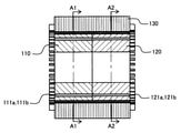
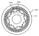
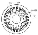
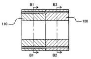
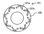
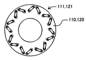
- FIG. 2 is a cross-sectional view taken along the line A1-A1 in FIG. 2 is a cross-sectional view taken along the line A2-A2 in FIG. It is a figure which shows by extracting the rotor core, and is the vertical sectional view in the plane including the rotation axis of a rotor core.
- FIG. 5 is a sectional view taken along line B1-B1 in FIG.
- FIG. 5 is a sectional view taken along line B2-B2 in FIG. It is a perspective view which looked at the rotor core from the direction of the rotation axis.
- FIG. 1 is an exploded view schematically showing the overall configuration of the rotary electric machine according to the present embodiment.
- 2 is a vertical cross-sectional view of a plane including the rotation axis of the rotary electric machine
- FIG. 3 is a cross-sectional view taken along the line A1-A1 in FIG. 2
- FIG. 4 is a cross-sectional view taken along the line A2-A2 in FIG. 5 to 8 are views showing the rotor core extracted
- FIG. 5 is a vertical sectional view in a plane including the rotation axis of the rotor core
- FIG. 6 is a sectional view taken along line B1-B1 in FIG.
- FIG. 7 is a sectional view taken along line B2-B2 in FIG.
- FIG. 8 is a perspective view of the rotor core as viewed from the direction of the rotation axis.
- the rotary electric machine 100 is formed in a cylindrical shape and a stator 130, respectively, and is rotatably arranged inside the stator 130 about a rotation axis.
- the first rotor core 110 and the second rotor core 120 are provided.
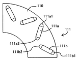
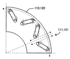
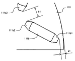
- FIG. 9 is a partially enlarged view of the first rotor core.
- the first rotor core 110 is arranged in a substantially V shape that opens radially outward when viewed from the rotation axis direction, and is embedded so as to extend in the rotation axis direction.
- a plurality of first magnet pairs 111 composed of 111a and 111b are arranged side by side in the circumferential direction, and first magnetic voids 111a1 and 111a2 are arranged at both ends in the longitudinal direction of the first magnets 111a and 111b when viewed from the rotation axis direction. , 111b1, 111b2 are formed.
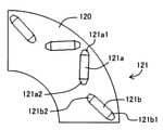
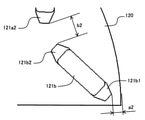
- FIG. 10 is a partially enlarged view of the second rotor core.
- the second rotor core 120 is arranged in a substantially V shape that opens radially outward when viewed from the rotation axis direction, and two second magnets embedded in a beam extending in the rotation axis direction.
- a plurality of second magnet pairs 121 composed of 121a and 121b are arranged side by side in the circumferential direction, and second magnetic voids 121a1 and 121a2 are arranged at both ends of the second magnets 121a and 121b in the longitudinal direction when viewed from the rotation axis direction.
- 121b1, 121b2 are formed.
- FIG. 11 is a partially perspective enlarged view of the rotor core as viewed from the direction of the rotation axis.
- 12 and 13 are enlarged views of the outer peripheral portions of the first rotor core and the second rotor core, respectively.
- the first rotor core 110 and the second rotor core 120 are the two second magnets of the second magnet pair 121 and the axis of symmetry of the two first magnets 111a and 111b of the first magnet pair 111.
- the two magnets 121a and 121b are arranged so as to overlap with each other when viewed from the direction of the rotation axis.
- the angle formed by the two first magnets 111a and 111b of the first magnet pair 111 arranged in a substantially V shape when viewed from the rotation axis direction is the two second magnets of the second magnet pair 121 arranged in a substantially V shape.
- the two magnets 121a and 121b are configured to be different from the angles formed when viewed from the direction of the rotation axis.
- the distance a2 between the second magnetic gap 121b1 and the outer periphery of the second rotor core 120, whichever is closer to, is equal to each other, and the two first magnets 111a, 111b of the first magnet pair 111 are closer to each other.
- the distance between the first magnetic gaps 111a2 and 111b2 and the distance between the second magnetic gaps 121a2 and 121b2 of the two second magnets 121a and 121b of the second magnet pair 121 that are closer to each other are equal to each other. There is.
- the main components of the synthetic torque ripple are the 6th-order component, the 12th-order component, and the 24th-order component.
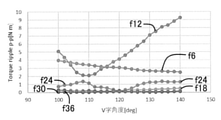
- FIG. 14 is a diagram showing the relationship between the angle between the two first magnets of the first magnet pair and the angle between the two second magnets of the second magnet pair and the size of each order component of the combined torque ripple.
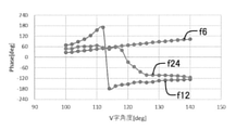
- FIG. 15 is a diagram showing the relationship between the angle between the two first magnets of the first magnet pair and the angle between the two second magnets of the second magnet pair and the phase in each order component of the combined torque ripple.
- FIG. 16 is a diagram showing the rate of change of the combined torque ripple with respect to the phase difference.
- the sixth-order component of the synthetic torque ripple has little variation with respect to the angle in both size and phase.
- the 12th-order component of the combined torque ripple has its magnitude reversed with respect to the variation with respect to the angle of 112 °, and its phase is also shifted by about 180 °. It can be said that the phase is almost inverted.
- the 24th-order component of the combined torque ripple has the same magnitude as the 12th-order component, and the fluctuation with respect to the angle is inverted with respect to 120 °, and the phase is also shifted by about 180 °.
- the angle is adjusted in order to reduce and optimize the 12th-order component of the combined torque ripple as much as possible. It is necessary to set it to 112 [deg], but in this case, the 24th-order component cannot be optimized. Further, in order to reduce and optimize the 24th order component of the synthetic torque ripple as much as possible, it is necessary to set the angle to 122 [deg], but in this case, the 12th order component cannot be optimized.
- the angle between the two first magnets of the first magnet pair and the two magnet pairs of the second magnet pair are arranged so that one angle is less than 110 [deg] and the other angle is larger than 122 [deg], and the first magnet pair 111 and the second magnet pair 121 are arranged.
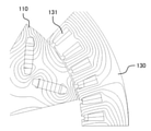
- FIG. 17 is a diagram showing the state of the magnetic flux in the outer peripheral portion of the rotating first rotor core and the stator
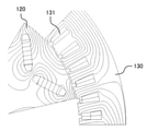
- FIG. 18 is a diagram showing the state of the magnetic flux in the outer peripheral portion and the stator of the rotating second rotor core. Is. 17 and 18 show the state of the magnetic flux at the same time.
- the combined torque ripple waveform changes. That is, it is higher by combining the first rotor core 110 and the second rotor core 120 in which the angles of the first magnet pair 111 and the second magnet pair 121 are set so that the combined torque ripple is reversed in the rotation axis direction.
- the combined torque ripple reduction effect can be obtained.
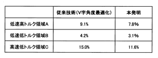
- FIG. 19 is a diagram showing the relationship between the rotation speed and the torque of the rotary electric machine. Further, FIG. 20 is a diagram showing the synthetic ripple reduction effect of the present invention on the prior art.
- the present embodiment not only the angles of the first magnet pair 111 and the second magnet pair 121, but also the insertion hole into which the first magnet pair 111 and the second magnet pair 121 are inserted (that is, the first magnetic gap 111a1). , 111a2, 111b1,111b2, and the arrangement position of the first magnet pair 111 and the second magnet pair 121 including the second magnetic voids 121a1, 121a2, 121b1, 121b2) were configured to be changed together. Therefore, as shown in FIGS. 19 and 20, a reduction effect on both the reluctance torque ripple and the reluctance torque ripple can be obtained.
- the low-speed high torque region A shown in FIG. 19 A combined torque ripple of 9.1%, 4.2%, and 15.0% is expected for each of the low-speed low torque region B and the high-speed low torque region C, but in the present invention, the combined torque ripple in each region is expected. It can be reduced to 7.8%, 3.1% and 11.6%.
- the distance a1 between the first magnetic gap 111a1 closer to the outer circumference of the first rotor core 110 and the outer circumference of the first rotor core 110 and the one closer to the outer circumference of the second rotor core 120 The first of the two first magnets 111a and 111b of the first magnet pair 111 so that the distance a2 between the second magnetic gap 121b1 and the outer periphery of the second rotor core 120 is equal to each other. Since the distance between the magnetic gaps 111a2 and 111b2 and the distance between the two second magnets 121a and 121b of the second magnet pair 121 which are closer to each other are equal to each other, the output average is set.
- the rotor core is formed in a columnar shape and is composed of two first magnets 111a and 111b arranged in a substantially V shape that opens radially outward when viewed from the rotation axis direction.
- a plurality of the first magnet pairs 111 are arranged side by side in the circumferential direction, and the first magnetic voids 111a1, 111a2, 111b1, 111b2 are formed at both ends in the longitudinal direction of the first magnets 111a and 111b viewed from the rotation axis direction.
- the first rotor core 110 and the columnar rotor core are arranged coaxially with the first rotor core 110 and are radially outward when viewed from the rotation axis direction.
- a plurality of second magnet pairs 121 composed of two second magnets 121a and 121b arranged in a substantially V shape to be opened are arranged side by side in the circumferential direction, and the longitudinal direction of the second magnets 121a and 121b viewed from the rotation axis direction.
- the second rotator core 120 in which the second magnetic voids 121a1, 121a2, 121b1, 121b2 are formed at both ends, and the first rotator core 110 and the second rotator core, which are formed in a cylindrical shape and coaxially inside.
- the angle formed by the two first magnets 111a and 111b of the first magnet pair 111 arranged in a substantially V shape with the stator 130 for arranging the 120 is arranged in a substantially V shape.
- It is configured to be different from the angle formed by the two second magnets 121a and 121b of the second magnet pair 121 when viewed from the rotation axis direction, and also includes the first magnetic voids 111a1, 111b1 and the outer periphery of the first rotor core 110. And the distance between the second magnetic gaps 121a1, 121b1 and the outer periphery of the second rotor core 120 are equal, and the first magnetic gaps 111a2 of the two first magnets 111a and 111b of the first magnet pair 111 are equal. , 111b2 and the distance of the second magnetic gaps 121a2 and 121b2 of the two second magnets 121a and 121b of the second magnet pair 121 are configured to be equal to each other.
- the torque ripple can be reduced in the current region.
- the length (thickness) of the first rotor core 110 and the second rotor core 120 in the rotation axis direction are the same will be illustrated and described. did.
- the phase difference between the torque ripple of the first rotor core 110 and the torque ripple of the second rotor core 120 constituting the combined torque ripple is 180 [deg]
- the magnitudes of the torque ripple may be different from each other. Be done. This also applies to other phase differences.
- the difference in the size of the torque ripple is reduced by combining the rotor cores having different thicknesses. It is possible to further enhance the effect of reducing the combined torque ripple.
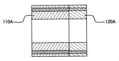
- the thickness of the first rotor core 110A and the second rotor core 120A in the rotation axis direction is changed.
- the length of the first rotor core 110A in the rotation axis direction is L1.
- the torque ripple is Tr (A)
- the length of the second rotor core 120A in the rotation axis direction is L2
- the torque ripple is Tr (B)
- L1 L ⁇ (Tr (B) / (Tr (A) + Tr.
- the third rotor core 140 may be provided between the first rotor core 110B and the second rotor core 120B.
- the third rotor core 140 is arranged in a substantially V shape that opens radially outward when viewed from the rotation axis direction, like the first rotor core 110B and the second rotor core 120B.
- a plurality of magnet pairs composed of two magnets embedded so as to extend in the direction are arranged side by side in the circumferential direction, and magnetic gaps are formed at both ends in the longitudinal direction of the magnets viewed from the rotation axis direction. ing.
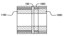
- the spacer 150 may be provided between the first rotor core 110C and the third rotor core 140C.
- the present invention is not limited to the above embodiment, and includes various modifications and combinations within a range not deviating from the gist thereof. Further, the present invention is not limited to the one including all the configurations described in the above-described embodiment, and includes the one in which a part of the configurations is deleted.
Landscapes
- Engineering & Computer Science (AREA)
- Power Engineering (AREA)
- Permanent Field Magnets Of Synchronous Machinery (AREA)
Abstract
略V字に配置された第1磁石対111の2つの第1磁石111a,111bの回転軸方向から見た成す角が、略V字に配置された第2磁石対121の2つの第2磁石121a,121bの回転軸方向から見た成す角と異なるように構成するとともに、第1磁気的空隙111a1,111b1と第1回転子コア110の外周との距離と第2磁気的空隙121a1,121b1と第2回転子コア120の外周との距離とが等しく、かつ、第1磁石対111の2つの第1磁石111a,111bの第1磁気的空隙111a2,111b2の距離と第2磁石対121の2つの第2磁石121a,121bの第2磁気的空隙121a2,121b2の距離とが等しくなるように構成する。これにより、出力トルクの減少を抑制しつつ、広い電流領域でトルクリプルを低減する回転電機を提供することができる。
Description
本発明は、回転電機に関する。
電気自動車やハイブリッド自動車に用いられる駆動用モータには大出力が求められるため、強力なエネルギーを保持する希土類の焼結磁石を用いた永久磁石式モータが一般に用いられている。駆動用モータには、永久磁石モータの内でも、低速大トルク、かつ、広範囲な回転速度領域という要求を満たすことができる埋込み磁石式モータが利用されている。
例えば、特許文献1には、軸心の回転軸を一体回転させる回転子と、該回転子を回転自在に収容する固定子と、を備えて、前記固定子は、前記回転子の周回回転する外周面に向かって延在して該外周面に内周面側を対面させる複数本のティース部と、駆動電力を入力するコイルを前記ティース部に巻き掛ける空間であって該ティース部間に形成される複数のスロットと、を有し、前記回転子には、前記ティース部の対向面に対する磁気力を働かせるように埋め込まれた複数の永久磁石と、該永久磁石の側方隣接箇所での磁束の回り込みを制限するように形成されている複数のフラックスバリアと、を有することにより、前記コイルへの通電時に発生する、前記ティース部内、当該ティース部背面側および前記回転子内を磁束が通過することによるリラクタンストルクおよび前記永久磁石との間で働く吸引力または反発力のマグネットトルクにより前記固定子内の前記回転子を回転駆動させる電動回転機であって、前記回転子側の1組の前記永久磁石および前記フラックスバリアと前記固定子側の1組の前記スロットとが対応する構成で、該1組のフラックスバリアを含む永久磁石側を1磁極としたときに、前記回転子の回転中心に対する、前記1磁極の前記フラックスバリアの外端部を含む磁極開口角度における前記1磁極の前記永久磁石の外端部の磁石開口角度の占める割合が、トルクの変動幅であるトルクリプルが最低範囲内に入るように、当該永久磁石側が配置されている電動回転機が開示されている。
また、特許文献2には、軸方向に貫通するスロットを周方向に等間隔に有する円環状のステータコアと、前記スロットに収容されるコイルと、径方向と直交する一文字状断面のマグネット収容孔を周方向に等間隔に有し、外周面が前記ステータコアの内周面と対向した状態で配置される円柱状のロータコアと、前記マグネット収容孔に収容される平板状のマグネットと、を備えた回転電機において、前記ロータコアは、前記マグネット収容孔の径方向外方側に形成され、前記マグネットに磁気的に接続されるセグメント極部と、前記セグメント極部の周方向の間に形成され、前記マグネット収容孔の径方向内方側の表面よりも径方向外方に突出する突極部とを有し、前記セグメント極部の開角は、電気角で135°~145°であり、前記突極部の開角は、電気角で23°~31°である回転電機が開示されている。
また、特許文献3には、磁石が挿入される穴が形成された回転子鉄心を有し、前記穴に永久磁石が挿入され、前記永久磁石の極間に磁気的補助突極部が形成された回転子であって、前記永久磁石の側面に磁気的空隙が設けられ、d軸に対して非対称かつq軸に対して対称に、前記回転子鉄心の磁気的補助突極部に第2の磁気的空隙が形成され、前記第2の磁気的空隙は、前記軸方向に垂直な断面において通電時のトルク脈動が打ち消されるように、q軸に対して周方向にずれて設けられており、前記第2の磁気的空隙は前記磁気的空隙とは独立して設けられ、前記永久磁石の極ピッチをτp、前記永久磁石とその側面に設けられた前記磁気的空隙とをあわせた角度をτgとしたとき、磁石穴極弧度τg/τpが0.5から0.9である回転子が開示されている。
自動車駆動用のモータは旧来、HEV(Hybrid Electric Vehicle)をーターゲットとしてきたため、低速~中速度域にのみ使用されてきたが、近年はBEV(Battery Electric Vehicle)の需要が増えつつあり、モータには高速回転化および全速度領域での低NVH(Noise, Vibration, Harshness)化が求められている。
上記特許文献1に記載の従来技術では、マグネット配置やマグネット周辺の空気領域の設計パラメータを最適化することでトルクリプルの最適化を図っている。しかしながら、トルクリプルの低減効果は必ずしも高くはない。また、特定の電流条件下でのみトルクリプルが低減されるため、電流条件によってはトルクリプルの低減効果が得られない場合も考えられる。
また、上記特許文献2に記載の従来技術では、リラクタンストルクとマグネットトルクを逆位相とすることでトルクリプルの低減を図っている。しかしながら、リラクタンストルクまたはマグネットトルクを意図的に低下させて合成トルクリプルを低減させているため、平均トルクが低下してしまうほか、電流条件によっては電流条件によっては合成トルクリプルが悪化してしまう場合が考えられる。
また、上記特許文献3に記載の従来技術では、ロータ外周に溝加工を施すことで構造的に磁束の流れを変化させて、ステータに鎖交する磁束の流れを変え、トルクリプル波形に掛け合わせる逆位相となるトルク波形を発生させることで、トルクリプルの相殺を図っている。しかしながら、また、特定の電流条件下でのみトルクリプルが低減されるため、電流条件によってはトルクリプルの低減効果が十分に得られない場合も考えられる。
また、従来技術としては、ロータスキューコアをずらして積層することでトルクリプルを低減する方法も知られているが、平均トルクが低下してしまうという問題を有している。
本発明は上記に鑑みてなされたものであり、出力トルクの減少を抑制しつつ、広い電流領域でトルクリプルを低減することができる回転電機を提供することを目的とする。
本願は上記課題を解決する手段を複数含んでいるが、その一例を挙げるならば、円柱状に形成された回転子コアであって、回転軸方向から見て径方向外側に開く略V字に配置された2つの第1磁石で構成された第1磁石対が周方向に複数並べて複数配置され、前記回転軸方向から見た前記第1磁石の長手方向両端部に第1磁気的空隙が形成された第1回転子コアと、円柱状に形成された回転子コアであって、前記第1回転子コアに対して同軸上に並べて配置され、かつ、回転軸方向から見て径方向外側に開く略V字に配置された2つの第2磁石で構成された第2磁石対が周方向に複数並べて複数配置され、前記回転軸方向から見た前記第2磁石の長手方向両端部に第2磁気的空隙が形成された第2回転子コアと、円筒状に形成され、内部に同軸上に第1回転子コアおよび第2回転子コアを配置する固定子とを備え、略V字に配置された前記第1磁石対の2つの第1磁石の前記回転軸方向から見た成す角は、略V字に配置された前記第2磁石対の2つの第2磁石の前記回転軸方向から見た成す角と異なるように構成されるとともに、前記第1磁気的空隙と前記第1回転子コアの外周との距離と前記第2磁気的空隙と前記第2回転子コアの外周との距離とが等しく、かつ、前記第1磁石対の2つの第1磁石の前記第1磁気的空隙の距離と前記第2磁石対の2つの第2磁石の前記第2磁気的空隙の距離とが等しいものとする。
本発明によれば、出力トルクの減少を抑制しつつ、広い電流領域でトルクリプルを低減することができる。
以下、本発明の実施の形態について図面を参照しつつ説明する。
<第1の実施の形態>
本発明の第1の実施の形態について図1~図20を参照しつつ説明する。
本発明の第1の実施の形態について図1~図20を参照しつつ説明する。
図1は、本実施の形態に係る回転電機の全体構成を概略的に示す分解図である。また、図2は、回転電機の回転軸を含む平面における縦断面図であり、図3は図2におけるA1-A1線断面図、図4は図2におけるA2-A2線断面図である。また、図5~図8は、回転子コアを抜き出して示す図であり、図5は回転子コアの回転軸を含む平面における縦断面図、図6は図5におけるB1-B1線断面図、図7は図5におけるB2-B2線断面図である。また、図8は、回転子コアを回転軸方向から見た透視図である。
図1に示すように、回転電機100は、円筒状に形成された固定子130と、それぞれ円柱状に形成され、固定子130の内部に回転軸を中心として同軸上に、回動可能に配置された第1回転子コア110及び第2回転子コア120とを備えている。
図9は、第1回転子コアの部分拡大図である。
図9に示すように、第1回転子コア110は、回転軸方向から見て径方向外側に開く略V字に配置され、回転軸方向に延在するように埋め込まれた2つの第1磁石111a,111bで構成された第1磁石対111が周方向に複数並べて複数配置され、回転軸方向から見た第1磁石111a,111bのそれぞれの長手方向両端部に第1磁気的空隙111a1,111a2,111b1,111b2が形成されている。
図10は、第2回転子コアの部分拡大図である。
図10に示すように、第2回転子コア120は、回転軸方向から見て径方向外側に開く略V字に配置され、回転軸方向に延在するりょうに埋め込まれた2つの第2磁石121a,121bで構成された第2磁石対121が周方向に複数並べて複数配置され、回転軸方向から見た第2磁石121a,121bのそれぞれの長手方向両端部に第2磁気的空隙121a1,121a2,121b1,121b2が形成されている。
図11は、回転子コアを回転軸方向から見た部分透視拡大図である。また、図12及び図13は、第1回転子コア及び第2回転子コアの外周部をそれぞれ拡大した図である。
図11に示すように、第1回転子コア110と第2回転子コア120とは、第1磁石対111の2つの第1磁石111a,111bの対称軸と第2磁石対121の2つの第2磁石121a,121bの対称軸とが回転軸方向から見て重なるように配置されている。また、略V字に配置された第1磁石対111の2つの第1磁石111a,111bの回転軸方向から見た成す角は、略V字に配置された第2磁石対121の2つの第2磁石121a,121bの回転軸方向から見た成す角と異なるように構成されている。
図11~図13に示すように、第1回転子コア110の外周に近い方の第1磁気的空隙111a1と第1回転子コア110の外周との距離a1と第2回転子コア120の外周に近い方の第2磁気的空隙121b1と第2回転子コア120の外周との距離a2とが等しくなるように、かつ、第1磁石対111の2つの第1磁石111a,111bの互いに近い方の第1磁気的空隙111a2,111b2の距離と第2磁石対121の2つの第2磁石121a,121bの互いに近い方の第2磁気的空隙121a2,121b2の距離とが等しくなるように構成されている。
なお、距離a1と距離a2とが等しい場合とは、具体的には、a1/b2=0.8~1.2を満たす場合のことを示している。同様に、距離b1と距離b2とが等しい場合とは、具体的には、b1/b2=0.8~1.2を満たす場合のことを示している。
ここで、本願発明の基本原理について説明する。
本願発明においては、合成トルク波形をFFTすることで、合成トルクリプルの主成分が6次成分、12次成分、及び24次成分であることを特定した。
図14は、第1磁石対の2つの第1磁石間の角度および第2磁石対の2つの第2磁石間の角度と合成トルクリプルの各次数成分における大きさの関係を示す図である。また、図15は、第1磁石対の2つの第1磁石間の角度および第2磁石対の2つの第2磁石間の角度と合成トルクリプルの各次数成分における位相の関係を示す図である。また、図16は、位相差に対する合成トルクリプルの変化率を示す図である。
図14及び図15に示すように、合成トルクリプルの6次成分は、大きさ及び位相共に角度に対する変動が少ないことがわかる。また、合成トルクリプルの12次成分は、角度に対する変動は112°を基準として大きさが反転しており、位相も約180°ずれている。これは、ほぼ位相が反転しているといえる。また、合成トルクリプルの24次成分は12次成分と同様に、角度に対する変動は120°を基準として大きさが反転しており、位相も約180°ずれている。
ここで、図16に示すように、相殺させたい成分の位相差φが180[deg]に近いほど、合成トルクリプルの位相差が無い場合に対する変化率が最適値(ゼロ)に近づくことがわかる。また、位相差が180[deg]に近くなくとも、多少なりとも位相差があることによって、位相差に対する合成トルクリプルの減少が見込まれる。なお、位相差に対するリプル変化率は、cos(θ/2)で与えられる。
例えば、第1磁石対の2つの第1磁石間の角度および第2磁石対の2つの第2磁石間の角度について、合成トルクリプルの12次成分をできるだけ低減して最適化するためには角度を112[deg]にする必要があるが、この場合には24次成分を最適化することが出来ない。また、合成トルクリプルの24次成分をできるだけ低減して最適化するためには角度を122[deg]にする必要があるが、この場合には12次成分を最適化することが出来ない。
そこで、本願発明においては、合成トルクリプルの12次成分および24次成分の両方を低減して最適化するために、第1磁石対の2つの第1磁石間の角度および第2磁石対の2つの第2磁石間の角度について、一方の角度が110[deg]未満となるように、他方の角度が122[deg]よりも大きくなるように配置し、第1磁石対111及び第2磁石対121をこのように配置した第1回転子コア110と第2回転子コア120とを組み合わせて回転電機100を構成することで、合成トルクリプルを低減させる。すなわち、上記条件を満たすように回転電機100を構成することで、合成トルクリプルの12次成分と24次成分の両方を低減して最適化することができる。
以上のように構成した本実施の形態における作用効果を説明する。
図17は、回転する第1回転子コアの外周部および固定子における磁束の様子を示す図であり、図18は回転する第2回転子コアの外周部および固定子における磁束の様子を示す図である。なお、図17及び図18は同時刻の磁束の様子を示している。
図17及び図18に示すように、第1磁石対111および第2磁石対121の角度を変えることで、各磁石対の極間部の磁束が変化し、固定子(ステータコア)に入る磁束も変化する。この結果、合成トルクリプル波形が変化する。すなわち、この合成トルクリプルが逆転するように第1磁石対111および第2磁石対121の角度を設定した第1回転子コア110及び第2回転子コア120を回転軸方向に組み合わせることで、より高い合成トルクリプル削減効果が得られる。
図19は、回転電機の回転速度とトルクの関係を示す図である。また、図20は、従来技術に対する本願発明の合成リプル削減効果を示す図である。
本実施の形態においては、第1磁石対111および第2磁石対121の角度だけではなく、第1磁石対111および第2磁石対121が挿入される挿入孔(すなわち、第1磁気的空隙111a1,111a2,111b1,111b2、及び、第2磁気的空隙121a1,121a2,121b1,121b2を含む第1磁石対111および第2磁石対121の配置位置)を併せて変えるように構成した。したがって、図19及び図20に示すように、マグネットトルクリプルとリラクタンストルクリプルの両方に対する低減効果が得られる。
例えば、回転子コアの外周と磁石対との距離が変わるように磁石対の角度を調整することで合成トルクリプルの最適化を図ろうとする従来技術においては、図19に示す低速高トルク領域A、低速低トルク領域B、及び、高速低トルク領域Cのそれぞれについて、9.1%、4,2%、15.0%の合成トルクリプルが見込まれるが、本願発明においては、各領域における合成トルクリプルを7.8%、3.1%、11.6%まで低減することができる。
また、本願発明においては、第1回転子コア110の外周に近い方の第1磁気的空隙111a1と第1回転子コア110の外周との距離a1と第2回転子コア120の外周に近い方の第2磁気的空隙121b1と第2回転子コア120の外周との距離a2とが等しくなるように、かつ、第1磁石対111の2つの第1磁石111a,111bの互いに近い方の第1磁気的空隙111a2,111b2の距離と第2磁石対121の2つの第2磁石121a,121bの互いに近い方の第2磁気的空隙121a2,121b2の距離とが等しくなるように構成したので、出力平均トルクの低下を抑制することができる(ただし、距離a1と距離a2とが等しい場合とは、a1/b2=0.8~1.2を満たす場合、距離b1と距離b2とが等しい場合とは、b1/b2=0.8~1.2を満たす場合のことを示すものとする)。
すなわち、本実施の形態においては、円柱状に形成された回転子コアであって、回転軸方向から見て径方向外側に開く略V字に配置された2つの第1磁石111a,111bで構成された第1磁石対111が周方向に複数並べて複数配置され、回転軸方向から見た第1磁石111a,111bの長手方向両端部に第1磁気的空隙111a1,111a2,111b1,111b2が形成された第1回転子コア110と、円柱状に形成された回転子コアであって、第1回転子コア110に対して同軸上に並べて配置され、かつ、回転軸方向から見て径方向外側に開く略V字に配置された2つの第2磁石121a,121bで構成された第2磁石対121が周方向に複数並べて複数配置され、回転軸方向から見た第2磁石121a,121bの長手方向両端部に第2磁気的空隙121a1,121a2,121b1,121b2が形成された第2回転子コア120と、円筒状に形成され、内部に同軸上に第1回転子コア110および第2回転子コア120を配置する固定子130とを備え、略V字に配置された第1磁石対111の2つの第1磁石111a,111bの回転軸方向から見た成す角は、略V字に配置された第2磁石対121の2つの第2磁石121a,121bの回転軸方向から見た成す角と異なるように構成されるとともに、第1磁気的空隙111a1,111b1と第1回転子コア110の外周との距離と第2磁気的空隙121a1,121b1と第2回転子コア120の外周との距離とが等しく、かつ、第1磁石対111の2つの第1磁石111a,111bの第1磁気的空隙111a2,111b2の距離と第2磁石対121の2つの第2磁石121a,121bの第2磁気的空隙121a2,121b2の距離とが等しくなるように構成したので、出力トルクの減少を抑制しつつ、広い電流領域でトルクリプルを低減することができる。
<その他の実施の形態>
本発明のその他の実施の形態について、図21~図24を参照しつつ説明する。
本発明のその他の実施の形態について、図21~図24を参照しつつ説明する。
図21に示すように、第1の実施の形態においては、第1回転子コア110と第2回転子コア120の回転軸方向の長さ(厚さ)を同じとした場合を例示して説明した。一方で、合成トルクリプルを構成する第1回転子コア110のトルクリプルと第2回転子コア120のトルクリプルとの位相差が180[deg]であったとしても、トルクリプルの大きさが互いに異なる場合が考えられる。これは、他の位相差の場合も同様である。
ここで、トルクリプルの大きさは、回転子コアの回転軸方向の長さ(厚さ)に依存することを考えると、厚さの異なる回転子コアを組み合わせることでトルクリプルの大きさの差異を小さくすることができ、合成トルクリプルの低減効果をより高めることができる。
そこで、図22に示すように、第1回転子コア110Aと第2回転子コア120Aの回転軸方向の厚さを変えることを考える。例えば、第1回転子コア110Aと第2回転子コア120Aの回転軸方向の厚さの合計がLとなるように構成する場合に、第1回転子コア110Aの回転軸方向の長さをL1、トルクリプルをTr(A)、第2回転子コア120Aの回転軸方向の長さをL2、トルクリプルをTr(B)とすると、L1=L×(Tr(B)/(Tr(A)+Tr(B)))を満たすように第1回転子コア110Aと第2回転子コア120Aの回転軸方向の厚さを調整することで、合成トルクリプルの低減効果をより高めることができる。
また、第1の実施の形態においては、第1回転子コア110と第2回転子コア120の2つを回転軸上に並べて配置する場合を例示して説明したが、例えば、図23に示すように、第1回転子コア110Bと第2回転子コア120Bの間に第3回転子コア140を設けるように構成しても良い。図示を省略するが、第3回転子コア140は第1回転子コア110Bや第2回転子コア120Bと同様に、回転軸方向から見て径方向外側に開く略V字に配置され、回転軸方向に延在するように埋め込まれた2つの磁石で構成された磁石対が周方向に複数並べて複数配置され、回転軸方向から見た磁石のそれぞれの長手方向両端部に磁気的空隙が形成されている。
また、図24に示すように、第1回転子コア110Cと第3回転子コア140Cの間にスペーサ150を設けるように構成しても良い。
その他の構成は第1の実施の形態と同様である。
以上のように構成した本実施の形態においても第1の実施の形態と同様の効果を得ることができる。
<付記>
なお、本発明は上記の実施の形態に限定されるものではなく、その要旨を逸脱しない範囲内の様々な変形例や組み合わせが含まれる。また、本発明は、上記の実施の形態で説明した全ての構成を備えるものに限定されず、その構成の一部を削除したものも含まれる。
なお、本発明は上記の実施の形態に限定されるものではなく、その要旨を逸脱しない範囲内の様々な変形例や組み合わせが含まれる。また、本発明は、上記の実施の形態で説明した全ての構成を備えるものに限定されず、その構成の一部を削除したものも含まれる。
100…回転電機、110,110A,110B,110C…第1回転子コア、111…第1磁石対、111a,111b…第1磁石、111a1,111a2,111b1,111b2…第1磁気的空隙、120,120A,120B…第2回転子コア、121…第2磁石対、121a,121b…第2磁石、121a1,121a2,121b1,121b2…第2磁気的空隙、130…固定子、140,140C…第3回転子コア、150…スペーサ
Claims (7)
- 円柱状に形成された回転子コアであって、回転軸方向から見て径方向外側に開く略V字に配置された2つの第1磁石で構成された第1磁石対が周方向に複数並べて複数配置され、前記回転軸方向から見た前記第1磁石の長手方向両端部に第1磁気的空隙が形成された第1回転子コアと、
円柱状に形成された回転子コアであって、前記第1回転子コアに対して同軸上に並べて配置され、かつ、回転軸方向から見て径方向外側に開く略V字に配置された2つの第2磁石で構成された第2磁石対が周方向に複数並べて複数配置され、前記回転軸方向から見た前記第2磁石の長手方向両端部に第2磁気的空隙が形成された第2回転子コアと、
円筒状に形成され、内部に同軸上に第1回転子コアおよび第2回転子コアを配置する固定子とを備え、
略V字に配置された前記第1磁石対の2つの第1磁石の前記回転軸方向から見た成す角は、略V字に配置された前記第2磁石対の2つの第2磁石の前記回転軸方向から見た成す角と異なるように構成されるとともに、
前記第1磁気的空隙と前記第1回転子コアの外周との距離と前記第2磁気的空隙と前記第2回転子コアの外周との距離とが等しく、かつ、前記第1磁石対の2つの第1磁石の前記第1磁気的空隙の距離と前記第2磁石対の2つの第2磁石の前記第2磁気的空隙の距離とが等しいことを特徴とする回転電機。 - 請求項1記載の回転電機において、
前記第1回転子コアと前記第2回転子コアとは、前記第1磁石対の2つの第1磁石の対称軸と前記第2磁石対の2つの第2磁石の対称軸とが前記回転軸方向から見て重なるように配置されたことを特徴とする回転電機。 - 請求項1記載の回転電機において、
前記第1回転子コアと前記第2回転子コアの前記回転軸方向の長さが等しいことを特徴とする回転電機。 - 請求項1記載の回転電機において、
前記第1回転子コアと前記第2回転子コアの前記回転軸方向の長さが異なることを特徴とする回転電機。 - 請求項1記載の回転電機において、
円柱状に形成された回転子コアであって、前記第1回転子コア及び前記第2回転子コアに対して同軸上に並べて配置され、かつ、回転軸方向から見て径方向外側に開く略V字に配置された2つの第3磁石で構成された第3磁石対が周方向に複数並べて複数配置され、前記回転軸方向から見た前記第3磁石の長手方向両端部に第3磁気的空隙が形成された第3回転子コアをさらに備え、
略V字に配置された前記第3磁石対の2つの第3磁石の前記回転軸方向から見た成す角は、略V字に配置された前記第1磁石対の2つの第1磁石の前記回転軸方向から見た成す角、及び、略V字に配置された前記第2磁石対の2つの第2磁石の前記回転軸方向から見た成す角と異なるように構成されるとともに、
前記第1磁気的空隙と前記第1回転子コアの外周との距離と前記第2磁気的空隙と前記第2回転子コアの外周との距離と前記第3磁気的空隙と前記第3回転子コアの外周との距離が等しく、かつ、前記第1磁石対の2つの第1磁石の前記第1磁気的空隙の距離と前記第2磁石対の2つの第2磁石の前記第2磁気的空隙の距離と前記第3磁石対の2つの第3磁石の前記第3磁気的空隙の距離とが等しいことを特徴とする回転電機。 - 請求項5記載の回転電機において、
前記第1回転子コアと前記第2回転子コアと前記第3回転子コアの前記回転軸方向の長さは、互いに異なることを特徴とする回転電機。 - 請求項1記載の回転電機において、
前記第1回転子コアと前記第2回転子コアとの間にスペーサを設けたことを特徴とする回転電機。
Applications Claiming Priority (2)
| Application Number | Priority Date | Filing Date | Title |
|---|---|---|---|
| JP2020-144444 | 2020-08-28 | ||
| JP2020144444A JP2023156535A (ja) | 2020-08-28 | 2020-08-28 | 回転電機 |
Publications (1)
| Publication Number | Publication Date |
|---|---|
| WO2022044534A1 true WO2022044534A1 (ja) | 2022-03-03 |
Family
ID=80353108
Family Applications (1)
| Application Number | Title | Priority Date | Filing Date |
|---|---|---|---|
| PCT/JP2021/024632 Ceased WO2022044534A1 (ja) | 2020-08-28 | 2021-06-29 | 回転電機 |
Country Status (2)
| Country | Link |
|---|---|
| JP (1) | JP2023156535A (ja) |
| WO (1) | WO2022044534A1 (ja) |
Citations (2)
| Publication number | Priority date | Publication date | Assignee | Title |
|---|---|---|---|---|
| JP2006115584A (ja) * | 2004-10-13 | 2006-04-27 | Asmo Co Ltd | 埋込磁石型モータ |
| WO2014199769A1 (ja) * | 2013-06-10 | 2014-12-18 | 三菱電機株式会社 | 回転電機 |
-
2020
- 2020-08-28 JP JP2020144444A patent/JP2023156535A/ja active Pending
-
2021
- 2021-06-29 WO PCT/JP2021/024632 patent/WO2022044534A1/ja not_active Ceased
Patent Citations (2)
| Publication number | Priority date | Publication date | Assignee | Title |
|---|---|---|---|---|
| JP2006115584A (ja) * | 2004-10-13 | 2006-04-27 | Asmo Co Ltd | 埋込磁石型モータ |
| WO2014199769A1 (ja) * | 2013-06-10 | 2014-12-18 | 三菱電機株式会社 | 回転電機 |
Also Published As
| Publication number | Publication date |
|---|---|
| JP2023156535A (ja) | 2023-10-25 |
Similar Documents
| Publication | Publication Date | Title |
|---|---|---|
| US7148597B2 (en) | Permanent magnet rotating electric machine | |
| US8227952B2 (en) | IPM type of synchronous machine | |
| JP4349089B2 (ja) | アキシャルギャップ回転電機 | |
| EP1990895B1 (en) | Stress distributing permanent magnet rotor geometry for electric machines | |
| US8102091B2 (en) | Interior permanent magnet motor including rotor with unequal poles | |
| US9071118B2 (en) | Axial motor | |
| JP4071510B2 (ja) | 電動機 | |
| US20090315424A1 (en) | Permanent magnet synchronous machine with shell magnets | |
| CN101165991A (zh) | 永磁磁阻电旋转机 | |
| Dajaku et al. | New methods for reducing the cogging torque and torque ripples of PMSM | |
| KR20220044429A (ko) | 서로 다른 회전자 세그먼트들을 적층한 전기 모터 및 그 설계 방법 | |
| JP2017204906A (ja) | スイッチトリラクタンスモータ | |
| JP2009050099A (ja) | 回転子コア、永久磁石回転子および永久磁石形同期回転電機 | |
| JP3672919B1 (ja) | 永久磁石型回転モータ | |
| US11837919B2 (en) | Rotary electric machine | |
| JP6760014B2 (ja) | 回転電機 | |
| JP3772819B2 (ja) | 同軸モータのロータ構造 | |
| CN110474455B (zh) | 具有混合转子拓扑结构的内置式永磁体机器 | |
| JP4080273B2 (ja) | 永久磁石埋め込み型電動機 | |
| JP2023156535A (ja) | 回転電機 | |
| JP2023183954A (ja) | 回転電機 | |
| JP2024007285A (ja) | 埋込磁石型回転子および回転電機 | |
| JP2007174885A (ja) | 同期電動機の回転子 | |
| CN114640202A (zh) | 转子组件及轴向磁通永磁电机 | |
| WO2021106153A1 (ja) | 回転電機 |
Legal Events
| Date | Code | Title | Description |
|---|---|---|---|
| 121 | Ep: the epo has been informed by wipo that ep was designated in this application |
Ref document number: 21860964 Country of ref document: EP Kind code of ref document: A1 |
|
| NENP | Non-entry into the national phase |
Ref country code: DE |
|
| 122 | Ep: pct application non-entry in european phase |
Ref document number: 21860964 Country of ref document: EP Kind code of ref document: A1 |
|
| NENP | Non-entry into the national phase |
Ref country code: JP |