WO2022044471A1 - 撮像システム - Google Patents
撮像システム Download PDFInfo
- Publication number
- WO2022044471A1 WO2022044471A1 PCT/JP2021/020972 JP2021020972W WO2022044471A1 WO 2022044471 A1 WO2022044471 A1 WO 2022044471A1 JP 2021020972 W JP2021020972 W JP 2021020972W WO 2022044471 A1 WO2022044471 A1 WO 2022044471A1
- Authority
- WO
- WIPO (PCT)
- Prior art keywords
- light
- image pickup
- unit
- incident
- objective lens
- Prior art date
- Legal status (The legal status is an assumption and is not a legal conclusion. Google has not performed a legal analysis and makes no representation as to the accuracy of the status listed.)
- Ceased
Links
Images


Classifications
-
- G—PHYSICS
- G02—OPTICS
- G02B—OPTICAL ELEMENTS, SYSTEMS OR APPARATUS
- G02B21/00—Microscopes
- G02B21/0004—Microscopes specially adapted for specific applications
- G02B21/002—Scanning microscopes
- G02B21/0024—Confocal scanning microscopes (CSOMs) or confocal "macroscopes"; Accessories which are not restricted to use with CSOMs, e.g. sample holders
- G02B21/0028—Confocal scanning microscopes (CSOMs) or confocal "macroscopes"; Accessories which are not restricted to use with CSOMs, e.g. sample holders specially adapted for specific applications, e.g. for endoscopes, ophthalmoscopes, attachments to conventional microscopes
-
- G—PHYSICS
- G01—MEASURING; TESTING
- G01N—INVESTIGATING OR ANALYSING MATERIALS BY DETERMINING THEIR CHEMICAL OR PHYSICAL PROPERTIES
- G01N21/00—Investigating or analysing materials by the use of optical means, i.e. using sub-millimetre waves, infrared, visible or ultraviolet light
- G01N21/17—Systems in which incident light is modified in accordance with the properties of the material investigated
-
- G—PHYSICS
- G01—MEASURING; TESTING
- G01N—INVESTIGATING OR ANALYSING MATERIALS BY DETERMINING THEIR CHEMICAL OR PHYSICAL PROPERTIES
- G01N21/00—Investigating or analysing materials by the use of optical means, i.e. using sub-millimetre waves, infrared, visible or ultraviolet light
- G01N21/62—Systems in which the material investigated is excited whereby it emits light or causes a change in wavelength of the incident light
- G01N21/63—Systems in which the material investigated is excited whereby it emits light or causes a change in wavelength of the incident light optically excited
- G01N21/64—Fluorescence; Phosphorescence
-
- G—PHYSICS
- G02—OPTICS
- G02B—OPTICAL ELEMENTS, SYSTEMS OR APPARATUS
- G02B21/00—Microscopes
- G02B21/0004—Microscopes specially adapted for specific applications
- G02B21/002—Scanning microscopes
- G02B21/0024—Confocal scanning microscopes (CSOMs) or confocal "macroscopes"; Accessories which are not restricted to use with CSOMs, e.g. sample holders
- G02B21/0032—Optical details of illumination, e.g. light-sources, pinholes, beam splitters, slits, fibers
-
- G—PHYSICS
- G02—OPTICS
- G02B—OPTICAL ELEMENTS, SYSTEMS OR APPARATUS
- G02B21/00—Microscopes
- G02B21/0004—Microscopes specially adapted for specific applications
- G02B21/002—Scanning microscopes
- G02B21/0024—Confocal scanning microscopes (CSOMs) or confocal "macroscopes"; Accessories which are not restricted to use with CSOMs, e.g. sample holders
- G02B21/0052—Optical details of the image generation
- G02B21/0056—Optical details of the image generation based on optical coherence, e.g. phase-contrast arrangements, interference arrangements
-
- G—PHYSICS
- G02—OPTICS
- G02B—OPTICAL ELEMENTS, SYSTEMS OR APPARATUS
- G02B21/00—Microscopes
- G02B21/0004—Microscopes specially adapted for specific applications
- G02B21/002—Scanning microscopes
- G02B21/0024—Confocal scanning microscopes (CSOMs) or confocal "macroscopes"; Accessories which are not restricted to use with CSOMs, e.g. sample holders
- G02B21/0052—Optical details of the image generation
- G02B21/006—Optical details of the image generation focusing arrangements; selection of the plane to be imaged
-
- G—PHYSICS
- G02—OPTICS
- G02B—OPTICAL ELEMENTS, SYSTEMS OR APPARATUS
- G02B21/00—Microscopes
- G02B21/0004—Microscopes specially adapted for specific applications
- G02B21/002—Scanning microscopes
- G02B21/0024—Confocal scanning microscopes (CSOMs) or confocal "macroscopes"; Accessories which are not restricted to use with CSOMs, e.g. sample holders
- G02B21/0052—Optical details of the image generation
- G02B21/0076—Optical details of the image generation arrangements using fluorescence or luminescence
-
- G—PHYSICS
- G02—OPTICS
- G02B—OPTICAL ELEMENTS, SYSTEMS OR APPARATUS
- G02B21/00—Microscopes
- G02B21/0004—Microscopes specially adapted for specific applications
- G02B21/002—Scanning microscopes
- G02B21/0024—Confocal scanning microscopes (CSOMs) or confocal "macroscopes"; Accessories which are not restricted to use with CSOMs, e.g. sample holders
- G02B21/008—Details of detection or image processing, including general computer control
-
- G—PHYSICS
- G02—OPTICS
- G02B—OPTICAL ELEMENTS, SYSTEMS OR APPARATUS
- G02B21/00—Microscopes
- G02B21/16—Microscopes adapted for ultraviolet illumination ; Fluorescence microscopes
-
- G—PHYSICS
- G02—OPTICS
- G02B—OPTICAL ELEMENTS, SYSTEMS OR APPARATUS
- G02B21/00—Microscopes
- G02B21/18—Arrangements with more than one light path, e.g. for comparing two specimens
-
- G—PHYSICS
- G02—OPTICS
- G02B—OPTICAL ELEMENTS, SYSTEMS OR APPARATUS
- G02B21/00—Microscopes
- G02B21/36—Microscopes arranged for photographic purposes or projection purposes or digital imaging or video purposes including associated control and data processing arrangements
- G02B21/361—Optical details, e.g. image relay to the camera or image sensor
-
- G—PHYSICS
- G02—OPTICS
- G02B—OPTICAL ELEMENTS, SYSTEMS OR APPARATUS
- G02B21/00—Microscopes
- G02B21/36—Microscopes arranged for photographic purposes or projection purposes or digital imaging or video purposes including associated control and data processing arrangements
- G02B21/365—Control or image processing arrangements for digital or video microscopes
- G02B21/367—Control or image processing arrangements for digital or video microscopes providing an output produced by processing a plurality of individual source images, e.g. image tiling, montage, composite images, depth sectioning, image comparison
Definitions
- the technology disclosed in the specification of the present application relates to an imaging system.
- OCT optical coherence tomography
- a sample or fluorescent protein stained with a fluorescent dye is irradiated with excitation light formed in a sheet shape, and the fluorescence emitted from the irradiation region of the light is emitted.
- An optical sheet microscope type image pickup device for detection has become widespread.
- OCT observation the external shape and internal shape of the object to be imaged are observed, and in fluorescence observation, the spatial distribution of a specific substance in the living body is observed.
- fluorescence observation is invasive when stained with a fluorescent dye. Therefore, these imaging methods are used properly according to the purpose.
- misalignment moves or rotation, etc.
- the accuracy of comparison and evaluation may be reduced.
- the technique disclosed in the present specification has been made in view of the problems described above, and is a technique for suppressing the misalignment of the image pickup target due to the switching of the image pickup method.
- the imaging system includes a first optical interference type imaging device for imaging an imaging target and an optical sheet microscope for imaging the imaging object.
- the second image pickup device of the method is provided, and the first image pickup device is provided in common with the light source unit provided in common with the second image pickup device and the second image pickup device, and is provided in common with the second image pickup device.
- a condensing unit for condensing the incident light on the imaging target, a reflecting unit for reflecting the incident light, and light incident from the light source unit are one of the light.
- the second image pickup apparatus includes the light source unit and the light source unit for calculating the interface position in the image pickup target based on the spectral distribution of the synthetic light. It is provided with the light collecting unit for condensing the light incident from the image on the image pickup target, and a second detection unit for detecting the fluorescence generated by the light collected on the image pickup target.
- the image pickup system relates to the image pickup system according to the first aspect, and the light source unit is a first for incident the light on the branch portion. It includes a light source and a second light source for incident the light on the light collecting unit.
- the image pickup system relates to the image pickup system according to the first or second aspect, and the condensing unit includes a first objective lens and the first objective lens.
- a second objective lens different from the objective lens is provided, and the first objective lens and the second objective lens can be switched according to the wavelength of the light incident on the condensing portion.
- the image pickup system relates to the image pickup system according to the second aspect, and the condensing unit is the light incident from the first light source.
- the first objective lens is made to correspond to the light incident from the second light source, and the second objective lens different from the first objective lens is made to correspond to the light, and the first objective lens and the second objective are made to correspond to each other.
- the lens can be switched according to the wavelength of the light incident on the condensing portion.
- the image pickup system according to the fifth aspect of the technique disclosed in the present specification relates to the image pickup system according to any one of the first to the fourth aspects, and the optical axis of the second detection unit is It is orthogonal to the optical axis of the light focused on the image pickup target by the light collecting unit.
- the image pickup system relates to the image pickup system according to any one of the first to fifth aspects, and further includes a container for accommodating the image pickup target.
- the container has a plurality of inner wall surfaces that are inclined with respect to the vertical direction, and the imaging target is arranged at a bottom portion sandwiched between the plurality of inner wall surfaces.
- the image pickup system relates to the image pickup system according to any one of the first to sixth aspects, and further includes a container for accommodating the image pickup target.
- the container has a plurality of outer wall surfaces, the first outer wall surface of the plurality of outer wall surfaces is orthogonal to the optical axis of the second detection unit, and the first outer wall surface of the plurality of outer wall surfaces is orthogonal to the optical axis of the second detection unit.
- the second outer wall surface is orthogonal to the optical axis of the light focused on the image pickup target by the light collecting unit.
- the image pickup system according to the eighth aspect of the technique disclosed in the present specification relates to the image pickup system according to any one of the first to seventh aspects, the first image pickup apparatus and the second image pickup system. It is further provided with a scanning unit that is commonly provided in the image pickup apparatus and for scanning the light that is focused on the image pickup target by the light collecting unit.
- the image pickup target is also used when switching the image pickup method according to each image pickup device. No need to move. Therefore, the position shift of the image pickup target due to the switching of the image pickup method is less likely to occur.
- FIG. 1 It is a figure which shows typically the example of the structure of the image pickup system which concerns on embodiment. It is a figure which conceptually shows the functional structure of a control part. It is a flowchart which shows the example of the operation of the image pickup system which concerns on embodiment. It is a figure which shows the example of the structure of the objective lens and its periphery in the image pickup system which an example is shown in FIG. It is a figure which shows the example of the structure of the objective lens and its periphery in the image pickup system which an example is shown in FIG. It is a figure which shows typically the example of the structure of the image pickup system which concerns on embodiment. It is a figure which conceptually shows the functional structure of a control part.
- ordinal numbers such as “first” or “second” may be used in the description described below, these terms facilitate the understanding of the content of the embodiments. It is used for convenience, and is not limited to the order that can be generated by these ordinal numbers.
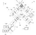
- FIG. 1 is a diagram schematically showing an example of a configuration of an imaging system according to the present embodiment.
- the image pickup system 1 connects an image pickup device 10 of an optical interference type, an image pickup device 20 of an optical sheet microscope type, and an image pickup device 10 and an image pickup device 20 via wireless or wired communication means.
- a control unit 30 for controlling the light is provided.
- the optical interference type image pickup device 10 is, for example, an OCT.
- OCT can observe tomography of living organisms or translucent materials in a non-contact and non-invasive manner.
- the OCT uses the interference phenomenon of light to detect the interface position in the depth direction inside the image pickup target including a living body and the like. Then, by performing the detection operation on a plurality of tomographic images, it is possible to obtain a tomographic image to be imaged and a three-dimensional structure to be imaged.
- the OCT includes a Fourier domain OCT (FD-OCT), which is a method that is widely used mainly in the medical field or the industrial field.
- FD-OCT Fourier domain OCT
- the image pickup apparatus 10 includes a light source 102, a detector 106, a branching and compositing system 12 connected to the light source 102 and the detector 106, and a reference system 14 and an object system 16 branching from the branching and compositing system 12.
- the light source 102 is a broadband light source having a wide wavelength region such as a super luminescent diode (SLD) or a femtosecond laser, and for example, a light source in the near infrared region having a wavelength of 700 nm or more and 1300 nm or less is used.
- SLD super luminescent diode
- femtosecond laser a light source in the near infrared region having a wavelength of 700 nm or more and 1300 nm or less is used.
- the detector 106 is, for example, a spectroscope such as a diffraction grating.
- the detector 106 detects the spectral distribution by spectrally decomposing the incident interference light.
- the branching and synthesizing system 12 includes a fiber coupler 104 connected to a light source 102 and a detector 106, and a beam splitter 108.
- the fiber coupler 104 emits the light incident from the light source 102 to the beam splitter 108. Further, the fiber coupler 104 emits light incident from the beam splitter 108 side to the detector 106.
- the fiber coupler 104 has a configuration having four so-called 2 ⁇ 2 type ports, the reference system 14 and the object system 16 are connected to the emission side, respectively, and the fiber coupler 104 alone branches and synthesizes the fiber coupler 104. It is also possible to configure.
- the beam splitter 108 is emitted from the fiber coupler 104, and then the light converted into parallel light by a collimator or the like is split into a reference system 14 and an object system 16 and emitted respectively. Further, the beam splitter 108 combines the light incident from the reference system 14 and the light incident from the object system 16 and outputs the light to the fiber coupler 104.
- the light branched in the beam splitter 108 is reflected by the mirror 112 via the relay lens 110. Then, the light reflected by the mirror 112 returns to the same optical path through the relay lens 110 and is incident on the beam splitter 108 as reference light.
- the light branched by the beam splitter 108 is transmitted through the dichroic mirror 114, and is further focused on the image pickup target via the galvano mirror 116, the relay lens 118, and the objective lens 120 (for example, at one point). It is incident in a condensed state).
- the imaging target is, for example, a sample 50 housed in a container 52 filled with a culture solution or the like.
- the outer wall surface of the container 52 is orthogonal to the optical axis of the object system 16 so as not to be affected by the refraction of light.
- the optical axis of the objective lens 204 is orthogonal to the optical axis. In other words, it is desirable to be orthogonal to the direction of the light entering the container on the incident side.
- the light reflected inside the sample 50 returns to the same optical path through the objective lens 120, the relay lens 118, the galvano mirror 116, and the dichroic mirror 114, and is incident on the beam splitter 108.
- the objective lens 120 is provided interchangeably with the objective lens 204 described later.
- the reference light incident from the reference system 14 and the light incident from the object system 16 are combined by the beam splitter 108 and incident on the detector 106 as the combined light via the fiber coupler 104.
- the image pickup device 20 includes a light source 202, an object system 16 common to the image pickup device 10, and an observation system 18.
- the light source 202 is, for example, a laser light source having a wavelength from the near-ultraviolet region to the visible region.
- the object system 16 is common to the image pickup apparatus 10, and the light converted into parallel light by a collimator or the like after being emitted from the light source 202 is a dichroic mirror arranged between the beam splitter 108 and the galvano mirror 116. It is reflected by the 114 and is further incident on the sample 50 to be imaged via the galvano mirror 116, the relay lens 118, and the objective lens 204. That is, the light from the light source 202 is directly incident on the object system 16.
- the objective lens 204 is provided interchangeably with the objective lens 120, and includes, for example, a cylindrical lens and the like.
- the light incident on the sample 50 through the objective lens 204 is light focused only in the Y-axis direction, that is, light having a sheet-like distribution spreading in the XZ plane (hereinafter, may be referred to as an optical sheet).
- the optical sheet irradiates an image pickup target previously stained with a fluorescent dye or an image pickup target which is a fluorescent protein, and excites the image pickup target located on the corresponding XZ plane to generate fluorescence from the image pickup target.
- the optical sheet forms light having a point-like distribution (a state in which the light is focused at one point) by an objective lens 204 or the like, and then scans the light at high speed in the X-axis direction with respect to the sample 50 (for example, described later). It may be substantially formed by performing scanning) sufficiently fast with respect to the shutter speed of the area camera.
- the observation system 18 includes an objective lens 206 in which the fluorescence generated from the sample 50 by the optical sheet is incident, and an area camera 212 in which the fluorescence incident on the objective lens 206 is incident through the bandpass filter 208 and the imaging lens 210.
- the bandpass filter 208 is a filter that transmits only light having a specific wavelength.
- the optical axis of the observation system 18 including the area camera 212 is orthogonal to the optical axis of the object system 16 including the objective lens 204.
- “orthogonal” includes “approximately orthogonality” in which the angle deviates within the range of tolerance, and also includes the case where the angle deviates within the range in which the XZ plane can be imaged to the same extent.
- the focal position of the observation system 18 (specifically, the focal position of the objective lens 206) is aligned with the XZ plane which is the irradiation region of light.
- it is desirable that the outer wall surface of the container 52 is orthogonal to the optical axis of the observation system 18 so as not to be affected by the refraction of light.
- the optical axis of the objective lens 206 is orthogonal to the optical axis. In other words, it is desirable to be orthogonal to the direction of the light entering the container on the incident side. According to the image detected by the area camera 212 based on the fluorescence generated from the sample 50 in the XZ plane, it is possible to obtain two-dimensional position information of the sample 50 that emits fluorescence in the plane.
- the two-dimensional position information of the sample 50 on the XZ plane can be collectively acquired from the image obtained by the area camera 212, so that the observation time can be set. It can be shortened to reduce the damage caused by the light irradiation of the sample 50.
- the control unit 30 is, for example, a hard disk drive (Hard disk drive, that is, HDD), a random access memory (random access memory, that is, RAM), a read-only memory (read only memory, that is, ROM), a flash memory, and volatileness.
- a storage device including a memory (storage medium) including a non-volatile semiconductor memory, a magnetic disk, a flexible disk, an optical disk, a compact disk, a mini disk, a DVD, or the like, and, for example, the storage device, an external CD-ROM, or an external device.
- Processing circuits such as a central processing unit (that is, a CPU) that executes a program stored in a DVD-ROM or an external flash memory, and a mouse, keyboard, touch panel, or various switches, etc. ,
- a central processing unit that is, a CPU
- An input device capable of inputting information and an output device capable of outputting information such as a display, a liquid crystal display device, or a lamp can be included.
- the imaging system 1 whose example is shown in FIG. 1 may be arranged so that the direction W1 corresponds to the vertical direction.
- the inner wall surface of the container 52 is inclined with respect to the direction W1 so that the sample 50 is fixed to the bottom portion 52A which is a corner portion of the container 52.
- the objective lens 120 or the objective lens 204 and the objective lens 206 are arranged facing the container 52 at a position looking up at the outer wall surface of the container 52.
- FIG. 2 is a diagram conceptually showing the functional configuration of the control unit 30.
- the control unit 30 has a drive control unit 32 for controlling the drive of the image pickup device 10 and the drive of the image pickup device 20, and the detection results obtained by the image pickup device 10 and the image pickup device 20. It is provided with an analysis unit 34 for analysis.
- the drive control unit 32 has a light amount and wavelength region of light emitted from the light source 102, a mirror 112 of the reference system 14, a galvano mirror 116 and an objective lens 120 of the object system 16, and a light amount and wavelength region of light emitted from the light source 202. , Controls the drive of the objective lens 206 and the area camera 212 of the observation system 18. Each mechanism is driven by a drive mechanism (not shown). Further, as such a drive mechanism, a known mechanism such as a motor can be used.
- the analysis unit 34 By Fourier transforming the data regarding the spectral distribution detected by the detector 106, the analysis unit 34 performs a depth direction in the sample 50 (direction along the optical axis of the object system 16) inherent in the spectral distribution of the interference light. That is, the data regarding the interface position in the direction along the Z-axis direction) is extracted. Further, the analysis unit 34 extracts the two-dimensional position data of the sample 50 that emits fluorescence by analyzing the data related to the image detected by the area camera 212.
- the image pickup device 10 detects the reflected scattered light generated at the interface of the image pickup target.
- the image pickup apparatus 20 detects fluorescence emitted from a specific substance. That is, the image pickup device 10 observes the external shape and the internal shape of the image pickup target, and the image pickup device 20 observes the spatial distribution of a specific substance in the image pickup target.
- the image pickup apparatus 10 can observe the image pickup target in a non-invasive manner.
- the image pickup apparatus 20 becomes an invasive observation when dyeing with a fluorescent dye. Therefore, it is common to use each image pickup device properly according to the purpose. However, as in the present embodiment, both the image pickup device 10 and the image pickup device 20 may be used.
- FIG. 3 is a flowchart showing an example of the operation of the imaging system 1 according to the present embodiment.
- step ST101 the user accommodates the sample 50 in the container 52.
- the sample 50 is dyed with a fluorescent dye as needed.
- step ST102 the control unit 30 causes the light from the light source 102 to enter the branching and synthesizing system 12. Then, the control unit 30 branches the light in the branching and synthesizing system 12, and incidents the light on the reference system 14 and the object system 16, respectively. At this time, the control unit 30 is set so that the objective lens 120 is located on the optical path of the incident light among the objective lenses 120 and the objective lenses 204 that are interchangeably provided in the object system 16.
- control unit 30 detects in the detector 106 the interference light between the light reflected by the mirror 112 in the reference system 14 and the light reflected inside the sample 50 in the object system 16 in the branching and synthesizing system 12. Let me.
- step ST103 the control unit 30 acquires data regarding the spectral distribution of the interference light detected by the detector 106. Further, the control unit 30 performs a Fourier transform of the data to extract data regarding the interface position in the sample 50 in the depth direction, which is inherent in the spectral distribution of the interference light.
- step ST104 the control unit 30 causes the light from the light source 202 to enter the object system 16 while stopping the emission of the light source 102.
- the sample 50 housed in the container 52 in step ST101 can be diverted as it is without changing the arrangement.
- the control unit 30 sets the objective lens 204 among the objective lenses 120 and the objective lenses 204 interchangeably provided in the object system 16 so as to be located on the optical path of the incident light.
- control unit 30 causes the area camera 212 to detect the fluorescence generated from the sample 50 by the optical sheet incident on the sample 50 via the objective lens 204 as an image.
- step ST105 the control unit 30 acquires data related to the image (fluorescent image) detected by the area camera 212, and further analyzes the data to obtain a two-dimensional sample 50 that emits fluorescence. Extract position data.
- the fluorescent image is detected by the image pickup device 20 after the interference light is detected by the image pickup device 10, but the order of these detections may be reversed.
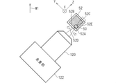
- FIG. 4 is a diagram showing an example of the configuration of the objective lens 120 and its surroundings in the image pickup system 1 shown in FIG. 1 as an example.
- FIG. 4 shows a state in which the objective lens 120 is located on the optical path of the incident light in the object system 16 of the imaging system 1 shown in FIG. 1 as an example.
- the light focused at one point by the objective lens 120 may be scanned in the XY plane by the scanning unit 122.
- Scanning by the scanning unit 122 is a method of changing the incident position of light by using an optical component that changes the optical path such as a galvano mirror, or moving at least one of the container 52 and the objective lens 120 on the XY plane. It can be realized by a method of changing these relative positions by making them.
- the inner wall surface 52B and the inner wall surface 52C of the container 52 are inclined with respect to the direction W1, so that the sample 50 becomes the inner wall surface 52B and the inner wall surface 52C. It is fixed to the bottom portion 52A, which is a corner portion sandwiched between the two.
- the outer wall surface 52D of the container 52 is orthogonal to the optical axis of the light focused on the sample 50 by the object system 16 so as not to be affected by the refraction of the light.
- a tomographic image of the sample 50 can be created.
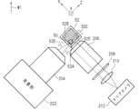
- FIG. 5 is a diagram showing an example of the configuration of the objective lens 204 and its surroundings in the image pickup system 1 shown in FIG. 1 as an example.
- FIG. 5 shows a state in which the objective lens 204 is located on the optical path of the incident light in the object system 16 of the imaging system 1 shown in FIG. 1 as an example.
- the optical sheet focused by the objective lens 204 may be scanned in the Y-axis direction by the scanning unit 222.
- Scanning by the scanning unit 222 is a method of changing the incident position of light by using an optical component that changes the optical path such as a galvano mirror, or moving at least one of the container 52 and the objective lens 204 in the Y-axis direction. It can be realized by a method of changing these relative positions by making them.
- the focal position of the observation system 18 is aligned with the XZ plane which is the light irradiation region, but when the light irradiation region moves in the Y-axis direction by the above scanning, the control unit 30 is the observation system.
- the focal position of 18 is also moved according to the irradiation region of light.
- the objective lens 204 is arranged facing the container 52 at a position looking up at the outer wall surface 52D of the container 52.
- the objective lens 206 is arranged facing the container 52 at a position looking up at the outer wall surface 52E of the container 52.
- the outer wall surface 52D of the container 52 is orthogonal to the optical axis of the object system 16 so as not to be affected by the refraction of light.
- the outer wall surface 52E of the container 52 be orthogonal to the optical axis of the observation system 18 so as not to be affected by the refraction of light.
- the scanning unit 222 may be the same as the scanning unit 122. That is, one scanning unit may be diverted to optical scanning in the image pickup device 10 and optical scanning in the image pickup device 20. In that case, the scanning unit can switch the scanning method between the optical scanning in the imaging device 10 and the optical scanning in the imaging device 20.
- a three-dimensional image of the sample 50 can be created.
- the resolution in the Y-axis direction at this time depends on the thickness of the optical sheet in the Y-axis direction.
- the present embodiment it is possible to perform image pickup as the image pickup apparatus 10 and image pickup as the image pickup apparatus 20 without moving the sample 50. Therefore, it is not necessary to consider the misalignment of the sample 50 when comparing the detection results (analysis results) of both images. Therefore, both detection results can be easily and highly accurately compared.
- the object system 16 is common to the image pickup device 10 and the image pickup device 20, it is possible to promote the miniaturization of the system configuration.
- FIG. 6 is a diagram schematically showing an example of the configuration of an imaging system according to the present embodiment.
- the imaging system 1A connects an optical interference type image pickup device 10A, an optical sheet microscope type image pickup device 20A, and an image pickup device 10A and an image pickup device 20A via wireless or wired communication means. It is provided with a control unit 30A for controlling.
- the optical interference type image pickup device 10A is, for example, an OCT.
- the image pickup apparatus 10A includes a light source 102A, a detector 106, a branching and compositing system 12 connected to the light source 102A and the detector 106, and a reference system 14 and an object system 16A branching from the branching and compositing system 12.
- the light source 102A for example, a light source in which the wavelength of the emitted light is variable in a wide wavelength region from the near-ultraviolet region to the near-infrared light region is used.
- the light branched in the beam splitter 108 is incident on the image pickup target via the galvano mirror 116, the relay lens 118, and the objective lens 120A (for example, in a state of being focused on one point). Be done.
- the light reflected inside the sample 50 returns to the same optical path through the objective lens 120A, the relay lens 118, and the galvano mirror 116, and is incident on the beam splitter 108.
- the reference light incident from the reference system 14 and the light incident from the object system 16A are combined by the beam splitter 108 and incident on the detector 106 as the combined light via the fiber coupler 104.
- the image pickup device 20A includes a light source 102A common to the image pickup device 10A, an object system 16A common to the image pickup device 10, and an observation system 18.
- the object system 16A is common to the image pickup device 10, and after being emitted from the light source 102A common to the image pickup device 10A, the light converted into parallel light by a collimator or the like is reflected by the beam splitter 108 and then galvano mirror. It is incident on the sample 50 through the 116, the relay lens 118, and the objective lens 120A.
- the light incident on the sample 50 via the objective lens 120A is light focused only in the Y-axis direction, that is, an optical sheet having a sheet-like distribution spreading in the XZ plane.
- the optical sheet forms light having a point-like distribution (a state in which the light is focused at one point) in the same manner as when the objective lens 120A operates as the object system 16A of the image pickup apparatus 10A, and then the light is emitted. It is formed by performing high-speed scanning on the sample 50 in the X-axis direction.
- the optical axis of the observation system 18 including the area camera 212 is orthogonal to the optical axis of the object system 16A including the objective lens 120A.
- the focal position of the observation system 18 is aligned with the XZ plane, which is the irradiation region of light.
- the control unit 30A includes, for example, a memory (storage medium) including an HDD, RAM, ROM, flash memory, volatile or non-volatile semiconductor memory, magnetic disk, flexible disk, optical disk, compact disk, mini disk, DVD, and the like.
- a storage device a processing circuit such as a CPU that executes a program stored in the storage device, an external CD-ROM, an external DVD-ROM, or an external flash memory, and a mouse, keyboard, and touch panel.
- an input device capable of inputting information such as various switches and an output device capable of outputting information such as a display, a liquid crystal display device, or a lamp can be included.
- FIG. 7 is a diagram conceptually showing the functional configuration of the control unit 30A.
- the control unit 30A has a drive control unit 32A for controlling the drive of the image pickup device 10A and the drive of the image pickup device 20A, and the detection results obtained by the image pickup device 10A and the image pickup device 20A. It is provided with an analysis unit 34A for analysis.
- the drive control unit 32A includes the amount and wavelength region of the light emitted from the light source 102A, the mirror 112 of the reference system 14, the galvano mirror 116 and the objective lens 120A of the object system 16A, the objective lens 206 of the observation system 18, the area camera 212, and the like. Control the drive of. Each mechanism is driven by a drive mechanism (not shown). Further, as such a drive mechanism, a known mechanism such as a motor can be used.
- the analysis unit 34A extracts the data regarding the interface position in the sample 50 in the depth direction inherent in the spectral distribution of the interference light by Fourier transforming the data regarding the spectral distribution detected by the detector 106. Further, the analysis unit 34A extracts the two-dimensional position data of the sample 50 that emits fluorescence by analyzing the data related to the image detected by the area camera 212.
- the operation of the imaging system 1A according to the present embodiment will be described.
- the image pickup system 1A according to the present embodiment by adjusting the wavelength region of the light emitted from the light source 102A and the corresponding scanning method, the image pickup as the image pickup device 10A and the image pickup as the image pickup device 20A are used properly. ..
- the control unit 30A when imaging as the image pickup apparatus 10A, the control unit 30A sets the wavelength region of the light emitted from the light source 102A to, for example, a wavelength of 700 nm or more and 1300 nm or less. Then, the light from the light source 102A is incident on the branching and synthesizing system 12. Then, the control unit 30A branches the light in the branching and synthesis system 12, and incidents the light on the reference system 14 and the object system 16A, respectively.
- control unit 30A detects in the detector 106 the interference light between the light reflected by the mirror 112 in the reference system 14 and the light reflected inside the sample 50 in the object system 16A in the branching and synthesizing system 12. Let me.
- the control unit 30A sets the wavelength region of the light emitted from the light source 102A from, for example, a near-ultraviolet region to a visible region. Then, the light from the light source 102A is incident on the branching and synthesizing system 12.
- control unit 30A uses the area camera 212 to image the fluorescence generated by the optical sheet incident on the sample 50 via the objective lens 120A and scanned by, for example, the scanning unit 222 shown in FIG. To be detected as.
- the sample 50 housed in the container 52 can be used as it is without changing the arrangement between the image pickup as the image pickup device 10A and the image pickup as the image pickup device 20A.
- the present embodiment it is possible to perform image pickup as the image pickup apparatus 10A and image pickup as the image pickup apparatus 20A without moving the sample 50. Therefore, it is not necessary to consider the misalignment of the sample 50 when comparing the detection results (analysis results) of both images. Therefore, both detection results can be easily and highly accurately compared.
- the light source 102A and the object system 16A having variable emission wavelengths are common in the image pickup apparatus 10A and the image pickup apparatus 20A, it is possible to promote the miniaturization of the system configuration.
- the replacement may be made across a plurality of embodiments. That is, it may be the case that the respective configurations shown in the examples in different embodiments are combined to produce the same effect.
- the image pickup system includes a first image pickup device of the optical interference method and a second image pickup device of the optical sheet microscope method.
- the first image pickup device corresponds to, for example, any one of the image pickup device 10, the image pickup device 10A, and the like (hereinafter, for convenience, any one of these is associated with each other. May be stated).
- the second image pickup device corresponds to, for example, any one of the image pickup device 20, the image pickup device 20A, and the like (hereinafter, for convenience, any one of these is described in correspondence with each other. May be).
- the image pickup apparatus 10A takes an image of an image pickup target.
- the image pickup target corresponds to, for example, a sample 50 or the like.
- the image pickup apparatus 20A also captures the sample 50.
- the image pickup apparatus 10A includes a light source unit, a light collecting unit, a reflection unit, a branch unit, a synthesis unit, a first detection unit, and a calculation unit.
- the light source unit corresponds to, for example, any one of the light source 102, the light source 102A, the light source 202, and the like (hereinafter, for convenience, any one of these will be described in correspondence with each other. In some cases).
- the light collecting unit corresponds to, for example, any one of the object system 16 and the object system 16A (hereinafter, for convenience, any one of these is described in association with each other).
- the reflecting unit corresponds to, for example, the reference system 14.
- the branching portion and the synthesizing portion correspond to, for example, the branching and synthesizing system 12.
- the first detection unit corresponds to, for example, the detector 106 and the like.
- the calculation unit corresponds to, for example, any one of the control unit 30, the control unit 30A, and the like (hereinafter, for convenience, any one of these may be described in correspondence with each other. be).
- the light source 102A is provided in common with the image pickup apparatus 20A.
- the object system 16A is provided in common with the image pickup apparatus 20A. Further, the object system 16A concentrates the incident light on the sample 50.
- the reference system 14 reflects the incident light.
- the branching and synthesizing system 12 branches the light incident from the light source 102A so that a part thereof is incident on the reference system 14 and the other part is incident on the object system 16A. Further, the branching and synthesizing system 12 combines the light reflected by the sample 50 and then incident through the object system 16A and the incident light after being reflected by the reference system 14 to emit synthetic light. ..
- the detector 106 detects the spectral distribution of the combined light (interference light).
- the control unit 30A calculates the interface position in the sample 50 based on the spectral distribution of the synthetic light.
- the image pickup apparatus 20A includes a light source 102A, an object system 16A, and a second detection unit.
- the second detection unit corresponds to, for example, the observation system 18.
- the object system 16A collects the light incident from the light source 102A on the sample 50.
- the observation system 18 detects the fluorescence generated by the light focused on the sample 50.
- the sample 50 is moved even when the image pickup method is switched according to each image pickup device. There is no need to let it. Therefore, the position shift of the sample 50 due to the switching of the imaging method is less likely to occur, and the imaging results can be easily compared between the two imaging methods. Further, since the light source 102A and the object system 16A are commonly provided between the image pickup device 10A and the image pickup device 20A, the configuration of the entire image pickup system can be miniaturized.
- the light source unit includes a first light source for incident light on the branching and synthetic system 12 and a second light source for incident light on the object system 16.
- the first light source corresponds to, for example, a light source 102 or the like.
- the second light source corresponds to, for example, a light source 202 or the like.
- the object system 16 includes a first objective lens and a second objective lens different from the objective lens 120.
- the first objective lens corresponds to, for example, the objective lens 120 and the like.
- the second objective lens corresponds to, for example, the objective lens 204.
- the objective lens 120 and the objective lens 204 can be switched according to the wavelength of the light incident on the object system 16. According to such a configuration, by switching the objective lens according to the wavelength of the light incident on the object system 16 from the light source, the image pickup as the optical interference type image pickup device 10 and the image pickup device of the optical sheet microscope type are performed. Imaging as 20 can be easily switched.
- the objective lens 120 corresponds to the light incident from the light source 102, and the objective lens 120 is different from the objective lens 120 to the light incident from the light source 202.
- the objective lens 120 and the objective lens 204 can be switched according to the wavelength of the light incident on the object system 16. According to such a configuration, by switching the objective lens according to the switching of the light source 102 and the light source 202, the image pickup as the optical interference type image pickup device 10 and the image pickup as the optical sheet microscope type image pickup device 20 can be performed. , Can be done while switching easily.
- the optical axis of the observation system 18 is orthogonal to the optical axis of the light focused on the sample 50 by the object system 16A. According to such a configuration, an image of the XZ plane of the sample 50 in which fluorescence is generated by the optical sheet can be appropriately acquired, and two-dimensional position information of the fluorescent substance on the plane can be obtained.
- the imaging system includes a container 52 for accommodating the sample 50.
- the container 52 has a plurality of inner wall surfaces (inner wall surface 52B, inner wall surface 52C) that are inclined with respect to the vertical direction. Then, the sample 50 is arranged on the bottom portion 52A sandwiched between the inner wall surface 52B and the inner wall surface 52C. According to such a configuration, since the sample 50 is fixed to the corner portion of the container 52, the position of the sample 50 is less likely to shift. Therefore, the position shift of the sample 50 due to the switching of the imaging method is less likely to occur, and the imaging results can be easily compared between the two imaging methods.
- the imaging system includes a container 52 for accommodating the sample 50.
- the container 52 has a plurality of outer wall surfaces (outer wall surface 52D, outer wall surface 52E).
- the outer wall surface 52E which is the first outer wall surface of the outer wall surface 52D and the outer wall surface 52E, is orthogonal to the optical axis of the observation system 18.
- the outer wall surface 52D which is the second outer wall surface of the outer wall surface 52D and the outer wall surface 52E, is orthogonal to the optical axis of the light focused on the sample 50 by the object system 16A.
- the imaging system includes a scanning unit 122 (or a scanning unit 222).
- the scanning unit 122 is provided in common with the image pickup device 10A and the image pickup device 20A, and the scanning unit 122 scans the light focused on the sample 50 by the object system 16A. According to such a configuration, it is possible to acquire the spectral distribution at a plurality of points of the sample 50 or to acquire a fluorescence image on a plurality of planes of the sample 50.
- the material name or the like when the material name or the like is described without being specified, the material contains other additives, for example, an alloy or the like, unless a contradiction occurs. It shall be included.
- each component in the embodiments described above is a conceptual unit, and within the scope of the technique disclosed herein, one component comprises a plurality of structures. It is assumed that one component corresponds to a part of a structure, and further, a case where a plurality of components are provided in one structure is included.
- each component in the above-described embodiment shall include a structure having another structure or shape as long as it exhibits the same function.
Landscapes
- Physics & Mathematics (AREA)
- Analytical Chemistry (AREA)
- General Physics & Mathematics (AREA)
- Chemical & Material Sciences (AREA)
- Optics & Photonics (AREA)
- Engineering & Computer Science (AREA)
- Multimedia (AREA)
- Health & Medical Sciences (AREA)
- General Health & Medical Sciences (AREA)
- Computer Vision & Pattern Recognition (AREA)
- General Engineering & Computer Science (AREA)
- Ophthalmology & Optometry (AREA)
- Radiology & Medical Imaging (AREA)
- Surgery (AREA)
- Pathology (AREA)
- Biochemistry (AREA)
- Immunology (AREA)
- Life Sciences & Earth Sciences (AREA)
- Nuclear Medicine, Radiotherapy & Molecular Imaging (AREA)
- Investigating, Analyzing Materials By Fluorescence Or Luminescence (AREA)
- Microscoopes, Condenser (AREA)
- Investigating Or Analysing Materials By Optical Means (AREA)
Priority Applications (1)
| Application Number | Priority Date | Filing Date | Title |
|---|---|---|---|
| US18/013,420 US12339429B2 (en) | 2020-08-31 | 2021-06-02 | Image capture system |
Applications Claiming Priority (2)
| Application Number | Priority Date | Filing Date | Title |
|---|---|---|---|
| JP2020-146103 | 2020-08-31 | ||
| JP2020146103A JP7455705B2 (ja) | 2020-08-31 | 2020-08-31 | 撮像システム |
Publications (1)
| Publication Number | Publication Date |
|---|---|
| WO2022044471A1 true WO2022044471A1 (ja) | 2022-03-03 |
Family
ID=80353083
Family Applications (1)
| Application Number | Title | Priority Date | Filing Date |
|---|---|---|---|
| PCT/JP2021/020972 Ceased WO2022044471A1 (ja) | 2020-08-31 | 2021-06-02 | 撮像システム |
Country Status (3)
| Country | Link |
|---|---|
| US (1) | US12339429B2 (enExample) |
| JP (1) | JP7455705B2 (enExample) |
| WO (1) | WO2022044471A1 (enExample) |
Cited By (1)
| Publication number | Priority date | Publication date | Assignee | Title |
|---|---|---|---|---|
| JP2025536885A (ja) * | 2022-09-29 | 2025-11-12 | アプライド マテリアルズ インコーポレイテッド | 表面粗さおよび放射率の判定 |
Citations (5)
| Publication number | Priority date | Publication date | Assignee | Title |
|---|---|---|---|---|
| WO2008052311A1 (en) * | 2006-10-05 | 2008-05-08 | Oti Ophthalmic Technologies Inc. | Optical imaging apparatus with spectral detector |
| JP2009264787A (ja) * | 2008-04-22 | 2009-11-12 | Topcon Corp | 光画像計測装置 |
| WO2017213712A2 (en) * | 2016-06-08 | 2017-12-14 | Massachusetts Institute Of Technology | Systems and methods for dual-more imaging using optical coherence tomography and fluorescence imaging |
| JP2018189395A (ja) * | 2017-04-28 | 2018-11-29 | 株式会社Screenホールディングス | 試料容器およびこれを用いる撮像方法 |
| WO2018231724A1 (en) * | 2017-06-12 | 2018-12-20 | Trustees Of Boston University | Systems and methods for oblique laser scanning |
Family Cites Families (3)
| Publication number | Priority date | Publication date | Assignee | Title |
|---|---|---|---|---|
| US8441633B2 (en) | 2009-10-29 | 2013-05-14 | California Institute Of Technology | Multiple-photon excitation light sheet illumination microscope |
| JP6444080B2 (ja) | 2014-07-14 | 2018-12-26 | キヤノン株式会社 | Oct装置およびその制御方法 |
| US20200096313A1 (en) * | 2018-09-21 | 2020-03-26 | SCREEN Holdings Co., Ltd. | Imaging apparatus and controlling method thereof |
-
2020
- 2020-08-31 JP JP2020146103A patent/JP7455705B2/ja active Active
-
2021
- 2021-06-02 WO PCT/JP2021/020972 patent/WO2022044471A1/ja not_active Ceased
- 2021-06-02 US US18/013,420 patent/US12339429B2/en active Active
Patent Citations (5)
| Publication number | Priority date | Publication date | Assignee | Title |
|---|---|---|---|---|
| WO2008052311A1 (en) * | 2006-10-05 | 2008-05-08 | Oti Ophthalmic Technologies Inc. | Optical imaging apparatus with spectral detector |
| JP2009264787A (ja) * | 2008-04-22 | 2009-11-12 | Topcon Corp | 光画像計測装置 |
| WO2017213712A2 (en) * | 2016-06-08 | 2017-12-14 | Massachusetts Institute Of Technology | Systems and methods for dual-more imaging using optical coherence tomography and fluorescence imaging |
| JP2018189395A (ja) * | 2017-04-28 | 2018-11-29 | 株式会社Screenホールディングス | 試料容器およびこれを用いる撮像方法 |
| WO2018231724A1 (en) * | 2017-06-12 | 2018-12-20 | Trustees Of Boston University | Systems and methods for oblique laser scanning |
Non-Patent Citations (1)
| Title |
|---|
| JU MYEONG JIN, SANG JIN LEE, YURI KIM, JUN GEUN SHIN, HAE YEON KIM, YIHENG LIM, YOSHIAKI YASUNO, AND BYEONG HA LEE: "Multimodal analysis of pearls and pearl treatments by using optical coherence tomography and fluorescence spectroscopy ", OPTICS EXPRESS, ELSEVIER, 11 April 2011 (2011-04-11), pages 6420 - 6432, XP055912496, Retrieved from the Internet <URL:https://opg.optica.org/DirectPDFAccess/8EE705DD-5220-4157-96B1E2FAAAFF4908_211210/oe-19-7-6420.pdf?da=1&id=211210&seq=0&mobile=no> [retrieved on 20220413] * |
Cited By (1)
| Publication number | Priority date | Publication date | Assignee | Title |
|---|---|---|---|---|
| JP2025536885A (ja) * | 2022-09-29 | 2025-11-12 | アプライド マテリアルズ インコーポレイテッド | 表面粗さおよび放射率の判定 |
Also Published As
| Publication number | Publication date |
|---|---|
| JP7455705B2 (ja) | 2024-03-26 |
| US20230266576A1 (en) | 2023-08-24 |
| JP2022041080A (ja) | 2022-03-11 |
| US12339429B2 (en) | 2025-06-24 |
Similar Documents
| Publication | Publication Date | Title |
|---|---|---|
| US20110261367A1 (en) | Integrated Confocal and Spectral-Domain Optical Coherence Tomography Microscope | |
| CN105980810B (zh) | 光学断层摄影装置和方法 | |
| HK1210827A1 (en) | System and method for parallel imaging optical coherence tomography | |
| CN113984732B (zh) | 一种凝视型线激光高光谱深度成像系统 | |
| US9955866B2 (en) | Optical tomographic imaging apparatus | |
| JP6018711B2 (ja) | 光断層観察装置 | |
| JP5527478B2 (ja) | 光干渉断層観察装置、画像間の相対位置決定方法および画像間の相対位置決定プログラム | |
| CN101617193A (zh) | 用于光学相干断层摄影的系统和方法 | |
| KR101919957B1 (ko) | 순간적 시간 영역 광 간섭 단층 촬영 | |
| JP5589374B2 (ja) | 顕微鏡装置 | |
| US8508748B1 (en) | Inspection system with fiber coupled OCT focusing | |
| WO2022044471A1 (ja) | 撮像システム | |
| JP3847703B2 (ja) | 光コヒーレンストモグラフィー装置 | |
| US11609412B2 (en) | Devices and methods for line-scanning microscopy | |
| KR20190045570A (ko) | 다중 광학 융합영상 기반 광학영상 생성장치 및 생성방법 | |
| JP5828811B2 (ja) | 撮像装置及びその制御方法 | |
| JP6728007B2 (ja) | 撮像装置および撮像方法 | |
| JP2016105126A (ja) | 顕微鏡装置 | |
| JP5131552B2 (ja) | 顕微鏡装置 | |
| EP2565625A1 (en) | Optical measurement system and method for operating an optical measurement system | |
| JP2025140175A (ja) | 生体組織識別装置、生体組織識別システム、生体組織識別方法及びプログラム | |
| KR20250149695A (ko) | 관찰 장치 및 관찰 방법 | |
| Kamal | Reflective optics-based line-scanning spectral domain optical coherence tomography system | |
| EP3186885A1 (en) | Method and system for heterodyned fluorescence tomography | |
| Makhlouf et al. | A dual modality fluorescence confocal and optical coherence tomography microendoscope |
Legal Events
| Date | Code | Title | Description |
|---|---|---|---|
| 121 | Ep: the epo has been informed by wipo that ep was designated in this application |
Ref document number: 21860902 Country of ref document: EP Kind code of ref document: A1 |
|
| NENP | Non-entry into the national phase |
Ref country code: DE |
|
| 122 | Ep: pct application non-entry in european phase |
Ref document number: 21860902 Country of ref document: EP Kind code of ref document: A1 |
|
| WWG | Wipo information: grant in national office |
Ref document number: 18013420 Country of ref document: US |