WO2022039130A1 - ロボット制御システム - Google Patents
ロボット制御システム Download PDFInfo
- Publication number
- WO2022039130A1 WO2022039130A1 PCT/JP2021/029930 JP2021029930W WO2022039130A1 WO 2022039130 A1 WO2022039130 A1 WO 2022039130A1 JP 2021029930 W JP2021029930 W JP 2021029930W WO 2022039130 A1 WO2022039130 A1 WO 2022039130A1
- Authority
- WO
- WIPO (PCT)
- Prior art keywords
- program
- robot
- robot control
- control device
- position data
- Prior art date
- Legal status (The legal status is an assumption and is not a legal conclusion. Google has not performed a legal analysis and makes no representation as to the accuracy of the status listed.)
- Ceased
Links
Images


Classifications
-
- B—PERFORMING OPERATIONS; TRANSPORTING
- B25—HAND TOOLS; PORTABLE POWER-DRIVEN TOOLS; MANIPULATORS
- B25J—MANIPULATORS; CHAMBERS PROVIDED WITH MANIPULATION DEVICES
- B25J9/00—Program-controlled manipulators
- B25J9/16—Program controls
- B25J9/1656—Program controls characterised by programming, planning systems for manipulators
- B25J9/1658—Program controls characterised by programming, planning systems for manipulators characterised by programming language
-
- B—PERFORMING OPERATIONS; TRANSPORTING
- B25—HAND TOOLS; PORTABLE POWER-DRIVEN TOOLS; MANIPULATORS
- B25J—MANIPULATORS; CHAMBERS PROVIDED WITH MANIPULATION DEVICES
- B25J9/00—Program-controlled manipulators
- B25J9/16—Program controls
- B25J9/1656—Program controls characterised by programming, planning systems for manipulators
-
- G—PHYSICS
- G05—CONTROLLING; REGULATING
- G05B—CONTROL OR REGULATING SYSTEMS IN GENERAL; FUNCTIONAL ELEMENTS OF SUCH SYSTEMS; MONITORING OR TESTING ARRANGEMENTS FOR SUCH SYSTEMS OR ELEMENTS
- G05B2219/00—Program-control systems
- G05B2219/30—Nc systems
- G05B2219/40—Robotics, robotics mapping to robotics vision
- G05B2219/40393—Learn natural high level command, associate its template with a plan, sequence
Definitions
- the present invention relates to a robot control system that controls a robot.
- Patent Document 1 a system for controlling an industrial robot by a PLC (programmable logic controller) is becoming widespread (for example, Patent Document 1).
- One aspect of the present disclosure is a robot control system including a host controller and a robot control device connected to the host controller, wherein the host controller operates with respect to the robot based on a control program for controlling the robot.
- the robot control device includes a control execution unit that transmits name information representing the name of the position data to the robot control device together with command information representing the command and position data accompanying the operation command, and the robot control device receives the command information.
- a program generation unit that generates an operation program for the robot based on the position data, and a name information addition unit that adds the name represented by the received name information to the position data in the operation program.
- a robot control system A robot control system.
- the user can easily grasp how the control program of the host controller and the operation program of the robot control device correspond to each other. As a result, it becomes possible to efficiently perform error investigation and debugging when performing teaching setting and programming.
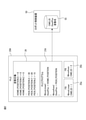
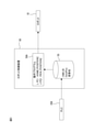
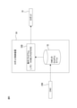
- FIG. 1 is a diagram showing an overall configuration of a robot control system according to an embodiment. It is a figure which shows the example of the PLC program when PLC is used as an upper controller. It is a figure which shows the operation program generated in the robot control device in the configuration of FIG. It is a figure which shows the example of the CNC program when CNC is used as an upper controller. It is a figure which shows the operation program generated in the robot control device in the configuration of FIG.
- FIG. 1 is a diagram showing the overall configuration of the robot control system 100 according to the embodiment.
- the robot control system 100 includes a higher-level controller 20, a robot control device 50, and a robot 10, and has a configuration in which a robot control device 50 that controls the robot 10 and a higher-level controller 20 are communicably connected to each other. ..
- the robot control system 100 is a system capable of creating a control program for the robot 10 on the host controller 20.
- the upper controller 20 transmits an operation command to the robot 10 to the robot control device 50 according to the control program of the robot 10 constructed on the upper controller 20.
- the robot control device 50 generates an operation program of the robot 10 based on an operation command transmitted from the host controller 20 to operate the robot 10.
- the host controller 20 may have a configuration as a general computer having a CPU, ROM, RAM, a storage device, an operation unit, a display unit, an input / output interface, a network interface, and the like.
- the host controller 20 is, for example, a PLC (programmable logic controller) or a CNC (numerical control device).
- various information processing devices such as a PC can be used in addition to the PLC and CNC.
- the robot control device 50 may have a configuration as a general computer having a CPU, ROM, RAM, a storage device, an operation unit, a display unit, an input / output interface, a network interface, and the like.
- a fieldbus, a wired or wireless LAN, or various other networks can be used for the connection between the host controller 20 and the robot control device 50.
- the host controller 20 has a control program 21 in the storage device for controlling the robot 10 built on the software environment on the host controller 20. Further, the host controller 20 has a control execution unit 22 and a communication interface 23. The control execution unit 22 interprets the control program 21 and transmits command information representing an operation command to the robot 10 to the robot control device 50 via the communication interface 23.
- the control execution unit 22 has a name indicating the name of the position data together with the instruction information indicating the operation instruction for the robot 10 and the position data accompanying the operation instruction. Information is transmitted to the robot control device 50.
- the robot control device 50 has a program generation unit 51, a name information addition unit 52, a program execution unit 53, and a communication interface 54.
- the program generation unit 51 generates an operation command of the robot 10 based on the instruction information transmitted from the host controller 20 and creates the operation program 56.
- the name information addition unit 52 converts the name of the position data into the position data as, for example, a comment sentence. Add to it.
- the program execution unit 53 executes the operation program 56 generated by the program generation unit 51 to operate the robot 10.
- FIG. 2 shows an example of a control program created on the PLC 20A (hereinafter, the control program constructed on the PLC is also referred to as a PLC program).
- the control program on the PLC can be written in a ladder language or a structured text language.
- the PLC program of FIG. 2 includes a variable definition 24, a PLC program main body 21A (hereinafter, simply referred to as PLC program 21A), and two function blocks (FB) 25a and 25b.
- PLC program 21A a PLC program main body 21A
- FB function blocks
- the variable definition 24 is a two-structure variable HOME. POSITION, PICK.
- the PLC program 21A includes a MoveLinear function which is an instruction to operate the robot linearly, and a MoveAccesss function which is an instruction to operate each axis of the robot.
- the operations of the MoveLinear function and the MoveAccesses function are defined in the function blocks (FB) 25a and 25b, respectively.
- the MoveLinear function the robot position data structure HOME. Enter POSITION.
- the function block 25a of the MoveLinear function it is defined that the numerical value 1 is set as the command ID corresponding to the MoveLinear function.
- the control execution unit 22 further has a variable name of position data attached to the operation instruction MoveLinear. POSITION'is included in the transmission data. That is, in this case, the control execution unit 22 transmits the following data to the robot control device.
- -Command ID 1
- -Position data (X, Y, Z) (0,0,0) ⁇ 'HOME.
- the function block 25b of the MoveAxes function it is defined to set a numerical value 2 as a command ID corresponding to the MoveAxes function.
- the control execution unit 22 further has a variable name of position data attached to the operation instruction MoveAxes.
- POSITION' is included in the transmission data. That is, in this case, the control execution unit 22 transmits the following data to the robot control device 50.
- the data transmitted from the PLC 20 is stored in, for example, the primary storage area 55 in the RAM of the robot control device 50.
- the program generation unit 51 generates an operation program of the robot 10 based on the data transmitted from the PLC 20A.
- the robot control device 50 may have a table in which command IDs and operation commands are associated with each other as shown in Table 1 below.
- the program generation unit 51 can recognize the operation instruction corresponding to the command ID transmitted from the PLC 20 by referring to this table.
- the PLC 20A also has the same table as in Table 1.
- the program execution unit 53 is configured to execute an operation instruction every time a new instruction statement is generated in the operation program 56A, and the above-mentioned'LP [1: HOME.
- POSITION]' is inserted into the operation program 56A, the program execution unit 53 linearly shifts the controlled target portion set in the movable portion of the robot 10 to the target position (home position) set in the position register P [1]. Move it.
- variable name representing the position data in the PLC program is inserted as a comment statement representing the position data in the operation program on the robot control device 50 side. That is, the text information assigned to the position data in the PLC program is reflected as the text information representing the position data in the operation program on the robot control device 50 side. Therefore, the user can easily grasp how the PLC program and the operation program correspond to each other. For example, assume a situation where there is an error in the position data input from the PLC to the robot control device. In this case, the user notices an error in the input data by stopping the robot at an unintended position, but if a large number of instructions are input from the PLC to the robot control device, there is an error in any instruction statement in the operation program.
- the position data in the operation program has a name common to the variable name in the PLC program, the position data having an error can be searched and easily found. That is, it is possible to efficiently perform error investigation and debugging when performing teaching setting and programming in the robot control system.
- FIG. 4 shows an example of a control program created on the CNC 20B (hereinafter, the control program constructed on the CNC is also referred to as a CNC program).
- the CNC program 21B with the G code of FIG. 4 includes the following contents.
- G90 Absolute command, which specifies that the coordinates are specified as absolute values.
- G01 Command linear operation. It operates at the following positions and speeds.
- the control execution unit 22 interprets the CNC program 21B and grasps that the instruction G01 commands a linear operation.
- ‘HOME.’ Is used as a label at the address specified by ‘D001’. It is assumed that POSITION'is set. In this case, the control execution unit 22 uses ‘HOME. POSITION'is transmitted to the robot control device 50.
- the command ID, position data, and label are temporarily stored in the primary storage area 55 in the robot control device 50.
- the label representing the position data in the CNC program 21B is inserted into the operation program 56B on the robot control device 50 side as a comment statement representing the position data. That is, the text information assigned to the position data in the CNC program 21B is reflected as the text information representing the position data in the operation program 56B on the robot control device 50 side. Therefore, the user can easily grasp how the CNC program and the operation program correspond to each other. That is, as in the case described above with respect to the PLC program, error investigation and debugging at the time of teaching setting and programming can be efficiently performed.
- the label freely set by the user in the memory area specified by the instruction code'D001' can be reflected as the name of the position data on the robot control device side, which is convenient for the user. You can further enhance your sex.
- the user can easily grasp how the control program of the host controller and the operation program of the robot control device correspond to each other. As a result, it becomes possible to efficiently perform error investigation and debugging when performing teaching setting and programming.
- the text information (variable name, label) itself is sent from the host controller to the robot control device as name information is shown, but instead of such a configuration, the name is expressed as name information.
- the identification information (ID) may be transmitted.
- each of the host controller and the robot control device is configured to have a table for associating the identification information with the character information.
- the function (control execution unit) of the host controller shown in FIG. 1 may be realized by the CPU of the host controller and the roller executing various software, or hardware such as ASIC (Application Specific Integrated Circuit) may be used. It may be realized by a main body configuration. Further, the functions (program generation unit, name information addition unit, program execution unit) of the robot control device 50 shown in FIG. 1 may be realized by the CPU of the robot control device executing various software, or may be realized. It may be realized by a configuration mainly composed of hardware such as ASIC.
- Robot 20 Upper controller 21 Control program 22 Control execution unit 23 Communication interface 24 Variable definition 25a, 25b Function block 20A Programmable logic controller 20B Numerical control device 21A PLC program 21B CNC program 50 Robot control device 51 Program generation unit 52 Name information addition unit 53 Program execution unit 54 Communication interface 55 Primary storage area 56, 56A, 56B Operation program 100 Robot control system
Landscapes
- Engineering & Computer Science (AREA)
- Robotics (AREA)
- Mechanical Engineering (AREA)
- Software Systems (AREA)
- Numerical Control (AREA)
- Manipulator (AREA)
- Programmable Controllers (AREA)
Priority Applications (4)
| Application Number | Priority Date | Filing Date | Title |
|---|---|---|---|
| DE112021004343.9T DE112021004343B4 (de) | 2020-08-20 | 2021-08-16 | Robotersteuersystem |
| JP2022543939A JP7397208B2 (ja) | 2020-08-20 | 2021-08-16 | ロボット制御システム |
| CN202180056891.0A CN116056841A (zh) | 2020-08-20 | 2021-08-16 | 机器人控制系统 |
| US18/006,067 US20230286149A1 (en) | 2020-08-20 | 2021-08-16 | Robot control system |
Applications Claiming Priority (2)
| Application Number | Priority Date | Filing Date | Title |
|---|---|---|---|
| JP2020-139400 | 2020-08-20 | ||
| JP2020139400 | 2020-08-20 |
Publications (1)
| Publication Number | Publication Date |
|---|---|
| WO2022039130A1 true WO2022039130A1 (ja) | 2022-02-24 |
Family
ID=80350332
Family Applications (1)
| Application Number | Title | Priority Date | Filing Date |
|---|---|---|---|
| PCT/JP2021/029930 Ceased WO2022039130A1 (ja) | 2020-08-20 | 2021-08-16 | ロボット制御システム |
Country Status (5)
| Country | Link |
|---|---|
| US (1) | US20230286149A1 (https=) |
| JP (1) | JP7397208B2 (https=) |
| CN (1) | CN116056841A (https=) |
| DE (1) | DE112021004343B4 (https=) |
| WO (1) | WO2022039130A1 (https=) |
Families Citing this family (1)
| Publication number | Priority date | Publication date | Assignee | Title |
|---|---|---|---|---|
| JP7613947B2 (ja) * | 2021-02-26 | 2025-01-15 | 株式会社安川電機 | ロボット制御システム、ロボットコントローラ、及びロボット制御方法 |
Citations (3)
| Publication number | Priority date | Publication date | Assignee | Title |
|---|---|---|---|---|
| JPH0772920A (ja) * | 1993-09-03 | 1995-03-17 | Hitachi Ltd | Faシステムの制御方法及び装置 |
| JP2004082216A (ja) * | 2002-06-28 | 2004-03-18 | Amada Eng Center Co Ltd | 曲げ加工方法およびその装置 |
| US20140142754A1 (en) * | 2011-07-27 | 2014-05-22 | Abb Technology Ag | System for commanding a robot |
Family Cites Families (8)
| Publication number | Priority date | Publication date | Assignee | Title |
|---|---|---|---|---|
| JP2005148789A (ja) * | 2003-11-11 | 2005-06-09 | Fanuc Ltd | 音声入力によるロボット教示プログラム編集装置 |
| JP4331186B2 (ja) * | 2006-07-13 | 2009-09-16 | 株式会社東芝 | モデル検査用情報生成装置およびプログラム |
| JP5877867B2 (ja) * | 2014-04-25 | 2016-03-08 | ファナック株式会社 | 複数台のロボットのシミュレーション装置 |
| JP6486679B2 (ja) * | 2014-12-25 | 2019-03-20 | 株式会社キーエンス | 画像処理装置、画像処理システム、画像処理方法及びコンピュータプログラム |
| JP2016163921A (ja) * | 2015-03-06 | 2016-09-08 | ファナック株式会社 | 曲げ加工機と同期動作するロボットを有するロボットシステム |
| JP6114361B1 (ja) * | 2015-11-02 | 2017-04-12 | ファナック株式会社 | オフラインのロボットプログラミング装置 |
| JP6983524B2 (ja) * | 2017-03-24 | 2021-12-17 | キヤノン株式会社 | 情報処理装置、情報処理方法およびプログラム |
| JP6625266B1 (ja) | 2018-03-23 | 2019-12-25 | 三菱電機株式会社 | ロボット制御装置 |
-
2021
- 2021-08-16 CN CN202180056891.0A patent/CN116056841A/zh not_active Withdrawn
- 2021-08-16 JP JP2022543939A patent/JP7397208B2/ja active Active
- 2021-08-16 WO PCT/JP2021/029930 patent/WO2022039130A1/ja not_active Ceased
- 2021-08-16 US US18/006,067 patent/US20230286149A1/en not_active Abandoned
- 2021-08-16 DE DE112021004343.9T patent/DE112021004343B4/de active Active
Patent Citations (3)
| Publication number | Priority date | Publication date | Assignee | Title |
|---|---|---|---|---|
| JPH0772920A (ja) * | 1993-09-03 | 1995-03-17 | Hitachi Ltd | Faシステムの制御方法及び装置 |
| JP2004082216A (ja) * | 2002-06-28 | 2004-03-18 | Amada Eng Center Co Ltd | 曲げ加工方法およびその装置 |
| US20140142754A1 (en) * | 2011-07-27 | 2014-05-22 | Abb Technology Ag | System for commanding a robot |
Also Published As
| Publication number | Publication date |
|---|---|
| JPWO2022039130A1 (https=) | 2022-02-24 |
| US20230286149A1 (en) | 2023-09-14 |
| DE112021004343B4 (de) | 2025-07-10 |
| DE112021004343T5 (de) | 2023-05-25 |
| JP7397208B2 (ja) | 2023-12-12 |
| CN116056841A (zh) | 2023-05-02 |
Similar Documents
| Publication | Publication Date | Title |
|---|---|---|
| US9063535B2 (en) | Numerical control program execution by robot | |
| CN107932504B (zh) | 基于PyQt的机械臂运行控制系统 | |
| CN107363812B (zh) | 无线控制的六自由度机械臂示教系统 | |
| US11648670B2 (en) | Machine tool system | |
| CN107544299B (zh) | 用于六自由度机械臂示教控制的pc端app系统 | |
| Sanfilippo et al. | JOpenShowVar: An open-source cross-platform communication interface to Kuka robots | |
| CN111775145B (zh) | 一种串并联机器人的控制系统 | |
| CN104699122A (zh) | 一种机器人运动控制系统 | |
| CN107901039A (zh) | 基于Python的桌面级机器人离线编程仿真系统 | |
| CN115734847B (zh) | 数值控制系统 | |
| CN104460675A (zh) | 一种码垛搬运机器人的控制系统 | |
| JP5291727B2 (ja) | 多軸同期動作機械のプログラム変換モジュール及びプログラム変換方法 | |
| JP7397208B2 (ja) | ロボット制御システム | |
| KR20180114837A (ko) | 로봇의 이동 속도 제어 장치 및 방법 | |
| KR102519698B1 (ko) | 로봇 제어 장치의 코딩 방법 및 프로그램과 로봇 제어 장치 | |
| WO2021235324A1 (ja) | ロボット制御装置及びロボットシステム | |
| JP2011062798A (ja) | ロボット制御装置およびロボット制御方法 | |
| CN115922684A (zh) | 用于六轴机器人的奇异点处理方法、装置、设备及介质 | |
| Mousavi Mohammadi et al. | A real-time impedance-based singularity and joint-limits avoidance approach for manual guidance of industrial robots | |
| Obeedat et al. | Development of a matlab toolbox for robot sensor interface (rsi) communication with kuka kr6 r900 sixx and validation by inverse kinematics approach | |
| CN118973770A (zh) | 执行机器人应用和创建用来执行机器人应用的程序 | |
| CN110202579B (zh) | 一种带视觉集成的多台机器人控制方法 | |
| CN109070357B (zh) | 工业机器人系统、控制系统及方法、控制器及计算设备 | |
| Rehbein et al. | Collaborative control with industrial robots | |
| Wruetz et al. | A wireless multi-robot network approach for industry 4.0 using RoBO2L |
Legal Events
| Date | Code | Title | Description |
|---|---|---|---|
| 121 | Ep: the epo has been informed by wipo that ep was designated in this application |
Ref document number: 21858274 Country of ref document: EP Kind code of ref document: A1 |
|
| ENP | Entry into the national phase |
Ref document number: 2022543939 Country of ref document: JP Kind code of ref document: A |
|
| 122 | Ep: pct application non-entry in european phase |
Ref document number: 21858274 Country of ref document: EP Kind code of ref document: A1 |
|
| WWG | Wipo information: grant in national office |
Ref document number: 112021004343 Country of ref document: DE |