WO2022039130A1 - Robot control system - Google Patents
Robot control system Download PDFInfo
- Publication number
- WO2022039130A1 WO2022039130A1 PCT/JP2021/029930 JP2021029930W WO2022039130A1 WO 2022039130 A1 WO2022039130 A1 WO 2022039130A1 JP 2021029930 W JP2021029930 W JP 2021029930W WO 2022039130 A1 WO2022039130 A1 WO 2022039130A1
- Authority
- WO
- WIPO (PCT)
- Prior art keywords
- program
- robot
- robot control
- control device
- position data
- Prior art date
Links
Images


Classifications
-
- B—PERFORMING OPERATIONS; TRANSPORTING
- B25—HAND TOOLS; PORTABLE POWER-DRIVEN TOOLS; MANIPULATORS
- B25J—MANIPULATORS; CHAMBERS PROVIDED WITH MANIPULATION DEVICES
- B25J9/00—Programme-controlled manipulators
- B25J9/16—Programme controls
- B25J9/1656—Programme controls characterised by programming, planning systems for manipulators
- B25J9/1658—Programme controls characterised by programming, planning systems for manipulators characterised by programming language
-
- B—PERFORMING OPERATIONS; TRANSPORTING
- B25—HAND TOOLS; PORTABLE POWER-DRIVEN TOOLS; MANIPULATORS
- B25J—MANIPULATORS; CHAMBERS PROVIDED WITH MANIPULATION DEVICES
- B25J9/00—Programme-controlled manipulators
- B25J9/16—Programme controls
- B25J9/1656—Programme controls characterised by programming, planning systems for manipulators
-
- G—PHYSICS
- G05—CONTROLLING; REGULATING
- G05B—CONTROL OR REGULATING SYSTEMS IN GENERAL; FUNCTIONAL ELEMENTS OF SUCH SYSTEMS; MONITORING OR TESTING ARRANGEMENTS FOR SUCH SYSTEMS OR ELEMENTS
- G05B2219/00—Program-control systems
- G05B2219/30—Nc systems
- G05B2219/40—Robotics, robotics mapping to robotics vision
- G05B2219/40393—Learn natural high level command, associate its template with a plan, sequence
Definitions
- the present invention relates to a robot control system that controls a robot.
- Patent Document 1 a system for controlling an industrial robot by a PLC (programmable logic controller) is becoming widespread (for example, Patent Document 1).
- One aspect of the present disclosure is a robot control system including a host controller and a robot control device connected to the host controller, wherein the host controller operates with respect to the robot based on a control program for controlling the robot.
- the robot control device includes a control execution unit that transmits name information representing the name of the position data to the robot control device together with command information representing the command and position data accompanying the operation command, and the robot control device receives the command information.
- a program generation unit that generates an operation program for the robot based on the position data, and a name information addition unit that adds the name represented by the received name information to the position data in the operation program.
- a robot control system A robot control system.
- the user can easily grasp how the control program of the host controller and the operation program of the robot control device correspond to each other. As a result, it becomes possible to efficiently perform error investigation and debugging when performing teaching setting and programming.
- FIG. 1 is a diagram showing an overall configuration of a robot control system according to an embodiment. It is a figure which shows the example of the PLC program when PLC is used as an upper controller. It is a figure which shows the operation program generated in the robot control device in the configuration of FIG. It is a figure which shows the example of the CNC program when CNC is used as an upper controller. It is a figure which shows the operation program generated in the robot control device in the configuration of FIG.
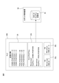
- FIG. 1 is a diagram showing the overall configuration of the robot control system 100 according to the embodiment.
- the robot control system 100 includes a higher-level controller 20, a robot control device 50, and a robot 10, and has a configuration in which a robot control device 50 that controls the robot 10 and a higher-level controller 20 are communicably connected to each other. ..
- the robot control system 100 is a system capable of creating a control program for the robot 10 on the host controller 20.
- the upper controller 20 transmits an operation command to the robot 10 to the robot control device 50 according to the control program of the robot 10 constructed on the upper controller 20.
- the robot control device 50 generates an operation program of the robot 10 based on an operation command transmitted from the host controller 20 to operate the robot 10.
- the host controller 20 may have a configuration as a general computer having a CPU, ROM, RAM, a storage device, an operation unit, a display unit, an input / output interface, a network interface, and the like.
- the host controller 20 is, for example, a PLC (programmable logic controller) or a CNC (numerical control device).
- various information processing devices such as a PC can be used in addition to the PLC and CNC.
- the robot control device 50 may have a configuration as a general computer having a CPU, ROM, RAM, a storage device, an operation unit, a display unit, an input / output interface, a network interface, and the like.
- a fieldbus, a wired or wireless LAN, or various other networks can be used for the connection between the host controller 20 and the robot control device 50.
- the host controller 20 has a control program 21 in the storage device for controlling the robot 10 built on the software environment on the host controller 20. Further, the host controller 20 has a control execution unit 22 and a communication interface 23. The control execution unit 22 interprets the control program 21 and transmits command information representing an operation command to the robot 10 to the robot control device 50 via the communication interface 23.
- the control execution unit 22 has a name indicating the name of the position data together with the instruction information indicating the operation instruction for the robot 10 and the position data accompanying the operation instruction. Information is transmitted to the robot control device 50.
- the robot control device 50 has a program generation unit 51, a name information addition unit 52, a program execution unit 53, and a communication interface 54.
- the program generation unit 51 generates an operation command of the robot 10 based on the instruction information transmitted from the host controller 20 and creates the operation program 56.
- the name information addition unit 52 converts the name of the position data into the position data as, for example, a comment sentence. Add to it.
- the program execution unit 53 executes the operation program 56 generated by the program generation unit 51 to operate the robot 10.
- FIG. 2 shows an example of a control program created on the PLC 20A (hereinafter, the control program constructed on the PLC is also referred to as a PLC program).
- the control program on the PLC can be written in a ladder language or a structured text language.
- the PLC program of FIG. 2 includes a variable definition 24, a PLC program main body 21A (hereinafter, simply referred to as PLC program 21A), and two function blocks (FB) 25a and 25b.
- PLC program 21A a PLC program main body 21A
- FB function blocks
- the variable definition 24 is a two-structure variable HOME. POSITION, PICK.
- the PLC program 21A includes a MoveLinear function which is an instruction to operate the robot linearly, and a MoveAccesss function which is an instruction to operate each axis of the robot.
- the operations of the MoveLinear function and the MoveAccesses function are defined in the function blocks (FB) 25a and 25b, respectively.
- the MoveLinear function the robot position data structure HOME. Enter POSITION.
- the function block 25a of the MoveLinear function it is defined that the numerical value 1 is set as the command ID corresponding to the MoveLinear function.
- the control execution unit 22 further has a variable name of position data attached to the operation instruction MoveLinear. POSITION'is included in the transmission data. That is, in this case, the control execution unit 22 transmits the following data to the robot control device.
- -Command ID 1
- -Position data (X, Y, Z) (0,0,0) ⁇ 'HOME.
- the function block 25b of the MoveAxes function it is defined to set a numerical value 2 as a command ID corresponding to the MoveAxes function.
- the control execution unit 22 further has a variable name of position data attached to the operation instruction MoveAxes.
- POSITION' is included in the transmission data. That is, in this case, the control execution unit 22 transmits the following data to the robot control device 50.
- the data transmitted from the PLC 20 is stored in, for example, the primary storage area 55 in the RAM of the robot control device 50.
- the program generation unit 51 generates an operation program of the robot 10 based on the data transmitted from the PLC 20A.
- the robot control device 50 may have a table in which command IDs and operation commands are associated with each other as shown in Table 1 below.
- the program generation unit 51 can recognize the operation instruction corresponding to the command ID transmitted from the PLC 20 by referring to this table.
- the PLC 20A also has the same table as in Table 1.
- the program execution unit 53 is configured to execute an operation instruction every time a new instruction statement is generated in the operation program 56A, and the above-mentioned'LP [1: HOME.
- POSITION]' is inserted into the operation program 56A, the program execution unit 53 linearly shifts the controlled target portion set in the movable portion of the robot 10 to the target position (home position) set in the position register P [1]. Move it.
- variable name representing the position data in the PLC program is inserted as a comment statement representing the position data in the operation program on the robot control device 50 side. That is, the text information assigned to the position data in the PLC program is reflected as the text information representing the position data in the operation program on the robot control device 50 side. Therefore, the user can easily grasp how the PLC program and the operation program correspond to each other. For example, assume a situation where there is an error in the position data input from the PLC to the robot control device. In this case, the user notices an error in the input data by stopping the robot at an unintended position, but if a large number of instructions are input from the PLC to the robot control device, there is an error in any instruction statement in the operation program.
- the position data in the operation program has a name common to the variable name in the PLC program, the position data having an error can be searched and easily found. That is, it is possible to efficiently perform error investigation and debugging when performing teaching setting and programming in the robot control system.
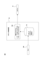
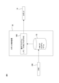
- FIG. 4 shows an example of a control program created on the CNC 20B (hereinafter, the control program constructed on the CNC is also referred to as a CNC program).
- the CNC program 21B with the G code of FIG. 4 includes the following contents.
- G90 Absolute command, which specifies that the coordinates are specified as absolute values.
- G01 Command linear operation. It operates at the following positions and speeds.
- the control execution unit 22 interprets the CNC program 21B and grasps that the instruction G01 commands a linear operation.
- ‘HOME.’ Is used as a label at the address specified by ‘D001’. It is assumed that POSITION'is set. In this case, the control execution unit 22 uses ‘HOME. POSITION'is transmitted to the robot control device 50.
- the command ID, position data, and label are temporarily stored in the primary storage area 55 in the robot control device 50.
- the label representing the position data in the CNC program 21B is inserted into the operation program 56B on the robot control device 50 side as a comment statement representing the position data. That is, the text information assigned to the position data in the CNC program 21B is reflected as the text information representing the position data in the operation program 56B on the robot control device 50 side. Therefore, the user can easily grasp how the CNC program and the operation program correspond to each other. That is, as in the case described above with respect to the PLC program, error investigation and debugging at the time of teaching setting and programming can be efficiently performed.
- the label freely set by the user in the memory area specified by the instruction code'D001' can be reflected as the name of the position data on the robot control device side, which is convenient for the user. You can further enhance your sex.
- the user can easily grasp how the control program of the host controller and the operation program of the robot control device correspond to each other. As a result, it becomes possible to efficiently perform error investigation and debugging when performing teaching setting and programming.
- the text information (variable name, label) itself is sent from the host controller to the robot control device as name information is shown, but instead of such a configuration, the name is expressed as name information.
- the identification information (ID) may be transmitted.
- each of the host controller and the robot control device is configured to have a table for associating the identification information with the character information.
- the function (control execution unit) of the host controller shown in FIG. 1 may be realized by the CPU of the host controller and the roller executing various software, or hardware such as ASIC (Application Specific Integrated Circuit) may be used. It may be realized by a main body configuration. Further, the functions (program generation unit, name information addition unit, program execution unit) of the robot control device 50 shown in FIG. 1 may be realized by the CPU of the robot control device executing various software, or may be realized. It may be realized by a configuration mainly composed of hardware such as ASIC.
- Robot 20 Upper controller 21 Control program 22 Control execution unit 23 Communication interface 24 Variable definition 25a, 25b Function block 20A Programmable logic controller 20B Numerical control device 21A PLC program 21B CNC program 50 Robot control device 51 Program generation unit 52 Name information addition unit 53 Program execution unit 54 Communication interface 55 Primary storage area 56, 56A, 56B Operation program 100 Robot control system
Landscapes
- Engineering & Computer Science (AREA)
- Robotics (AREA)
- Mechanical Engineering (AREA)
- Software Systems (AREA)
- Numerical Control (AREA)
- Programmable Controllers (AREA)
Abstract
Provided is a robot control system which enables a user to easily understand correspondence between a program for a higher-level controller and an operation program for a robot control device. A robot control system 100 comprises a higher-level controller 20 and a robot control device 50. The higher-level controller 20 includes a control execution unit 22 that transmits, to the robot control device 50, command information indicating an operation command to a robot, position data accompanying the operation command, and name information indicating the name of the position data, according to a control program for controlling the robot. The robot control device 50 includes a program production unit 51 that produces an operation program for the robot on the basis of the received command information and position data, and a name information addition unit 52 that adds the received name to the position data in the operation program.
Description
本発明は、ロボットを制御するロボット制御システムに関する。
The present invention relates to a robot control system that controls a robot.
産業用ロボットは、教示操作盤或いはプログラミング装置を用いて作成された動作プログラムをロボット制御装置にローディングし、ロボット制御装置から制御して動作させるのが一般的である。他方、近年、PLC(プログラマブルロジックコントローラ)により産業ロボットを制御するシステムも普及しつつある(例えば、特許文献1)。
In an industrial robot, it is common to load an operation program created by using a teaching operation panel or a programming device into a robot control device and control the operation from the robot control device. On the other hand, in recent years, a system for controlling an industrial robot by a PLC (programmable logic controller) is becoming widespread (for example, Patent Document 1).
近年、PLCopen(登録商標)規格等の普及により、産業用ロボットの制御のためのPLCプログラムの開発環境の整備も進展している。PLCを用いたロボット制御システムでは、一般に、PLCプログラムの実行によりPLCからロボット制御装置にロボットに対する動作命令が送信され、ロボット制御装置側でPLCからの動作命令に基づいて動作プログラムを生成しロボットを制御する。このようなロボット制御システムにおいて、PLCプログラムを用いたロボットの教示設定や、PLCプログラム開発時の動作確認を行う場面を想定すると、PLCプログラムとロボット制御装置側の動作プログラムとは異なるプログラム仕様であるため、PLCプログラムとロボット制御装置の動作プログラムとの対応はユーザにとって分かりづらく、エラー発生時の調査等に時間を要することとなる。
In recent years, with the spread of PLCopen (registered trademark) standards, etc., the development environment for PLC programs for controlling industrial robots has been improved. In a robot control system using a PLC, in general, an operation command is transmitted from the PLC to the robot control device by executing a PLC program, and the robot control device generates an operation program based on the operation command from the PLC to generate a robot. Control. In such a robot control system, assuming a situation where the instruction setting of the robot using the PLC program and the operation check at the time of PLC program development are performed, the PLC program and the operation program on the robot control device side have different program specifications. Therefore, it is difficult for the user to understand the correspondence between the PLC program and the operation program of the robot control device, and it takes time to investigate when an error occurs.
本開示の一態様は、上位コントローラと、該上位コントローラに接続されたロボット制御装置とを備えるロボット制御システムにおいて、前記上位コントローラは、ロボットを制御するための制御プログラムに基づいて、前記ロボットに対する動作命令を表す命令情報及び該動作命令に付随する位置データと共に、該位置データの名称を表す名称情報を前記ロボット制御装置に送信する制御実行部を備え、前記ロボット制御装置は、受信した前記命令情報と前記位置データとに基づいて前記ロボットに対する動作プログラムを生成するプログラム生成部と、受信した前記名称情報が表す前記名称を、前記動作プログラム内の前記位置データに対して付加する名称情報付加部と、を備えるロボット制御システムである。
One aspect of the present disclosure is a robot control system including a host controller and a robot control device connected to the host controller, wherein the host controller operates with respect to the robot based on a control program for controlling the robot. The robot control device includes a control execution unit that transmits name information representing the name of the position data to the robot control device together with command information representing the command and position data accompanying the operation command, and the robot control device receives the command information. A program generation unit that generates an operation program for the robot based on the position data, and a name information addition unit that adds the name represented by the received name information to the position data in the operation program. , A robot control system.
上記構成によれば、ユーザは、上位コントローラの制御プログラムとロボット制御装置の動作プログラムとがどのように対応しているかを容易に把握することができる。それにより、教示設定やプログラミングを行う際のエラー調査やデバッグを効率的に行うことが可能となる。
According to the above configuration, the user can easily grasp how the control program of the host controller and the operation program of the robot control device correspond to each other. As a result, it becomes possible to efficiently perform error investigation and debugging when performing teaching setting and programming.
添付図面に示される本発明の典型的な実施形態の詳細な説明から、本発明のこれらの目的、特徴および利点ならびに他の目的、特徴および利点がさらに明確になるであろう。
From the detailed description of typical embodiments of the invention shown in the accompanying drawings, these objectives, features and advantages as well as other objectives, features and advantages of the present invention will be further clarified.
次に、本開示の実施形態について図面を参照して説明する。参照する図面において、同様の構成部分または機能部分には同様の参照符号が付けられている。理解を容易にするために、これらの図面は縮尺を適宜変更している。また、図面に示される形態は本発明を実施するための一つの例であり、本発明は図示された形態に限定されるものではない。
Next, the embodiments of the present disclosure will be described with reference to the drawings. In the drawings to be referenced, similar components or functional parts are designated by the same reference numerals. These drawings have been scaled accordingly for ease of understanding. Further, the form shown in the drawings is an example for carrying out the present invention, and the present invention is not limited to the illustrated form.
図1は一実施形態に係るロボット制御システム100の全体構成を表す図である。ロボット制御システム100は、上位コントローラ20と、ロボット制御装置50と、ロボット10とを備え、ロボット10を制御するロボット制御装置50と、上位コントローラ20とが通信可能に接続された構成となっている。ロボット制御システム100は、上位コントローラ20上でロボット10に対する制御プログラムを作成することができるシステムである。上位コントローラ20は、上位コントローラ20上で構築されたロボット10の制御プログラムにしたがって、ロボット10に対する動作命令をロボット制御装置50に対して送信する。ロボット制御装置50は、上位コントローラ20から送信されてきた動作命令に基づいてロボット10の動作プログラムを生成してロボット10を動作させる。
FIG. 1 is a diagram showing the overall configuration of the robot control system 100 according to the embodiment. The robot control system 100 includes a higher-level controller 20, a robot control device 50, and a robot 10, and has a configuration in which a robot control device 50 that controls the robot 10 and a higher-level controller 20 are communicably connected to each other. .. The robot control system 100 is a system capable of creating a control program for the robot 10 on the host controller 20. The upper controller 20 transmits an operation command to the robot 10 to the robot control device 50 according to the control program of the robot 10 constructed on the upper controller 20. The robot control device 50 generates an operation program of the robot 10 based on an operation command transmitted from the host controller 20 to operate the robot 10.
上位コントローラ20は、CPU、ROM、RAM、記憶装置、操作部、表示部、入出力インタフェース、ネットワークインタフェース等を有する一般的なコンピュータとしての構成を有していても良い。上位コントローラ20は、例えば、PLC(プログラマブルロジックコントローラ)、或いはCNC(数値制御装置)である。なお、上位コントローラ20としては、PLC、CNC以外にもPC等の各種情報処理装置を用いることができる。ロボット制御装置50は、CPU、ROM、RAM、記憶装置、操作部、表示部、入出力インタフェース、ネットワークインタフェース等を有する一般的なコンピュータとしての構成を有していても良い。なお、上位コントローラ20とロボット制御装置50間の接続には、フィールドバス、有線又は無線LAN、その他各種ネットワークを用いることができる。
The host controller 20 may have a configuration as a general computer having a CPU, ROM, RAM, a storage device, an operation unit, a display unit, an input / output interface, a network interface, and the like. The host controller 20 is, for example, a PLC (programmable logic controller) or a CNC (numerical control device). As the host controller 20, various information processing devices such as a PC can be used in addition to the PLC and CNC. The robot control device 50 may have a configuration as a general computer having a CPU, ROM, RAM, a storage device, an operation unit, a display unit, an input / output interface, a network interface, and the like. A fieldbus, a wired or wireless LAN, or various other networks can be used for the connection between the host controller 20 and the robot control device 50.
図1に示すように上位コントローラ20は、記憶装置内に、上位コントローラ20上のソフトウェア環境上で構築されたロボット10を制御するための制御プログラム21を保有している。更に、上位コントローラ20は、制御実行部22と、通信インタフェース23とを有する。制御実行部22は、制御プログラム21を解釈し、ロボット10に対する動作命令を表す命令情報を通信インタフェース23を介してロボット制御装置50に送信する。制御プログラム21における命令が位置データを伴う動作命令である場合、制御実行部22は、ロボット10に対する動作命令を表す命令情報及び該動作命令に付随する位置データと共に、該位置データの名称を表す名称情報をロボット制御装置50に送信する。
As shown in FIG. 1, the host controller 20 has a control program 21 in the storage device for controlling the robot 10 built on the software environment on the host controller 20. Further, the host controller 20 has a control execution unit 22 and a communication interface 23. The control execution unit 22 interprets the control program 21 and transmits command information representing an operation command to the robot 10 to the robot control device 50 via the communication interface 23. When the instruction in the control program 21 is an operation instruction accompanied by position data, the control execution unit 22 has a name indicating the name of the position data together with the instruction information indicating the operation instruction for the robot 10 and the position data accompanying the operation instruction. Information is transmitted to the robot control device 50.
ロボット制御装置50は、プログラム生成部51と、名称情報付加部52と、プログラム実行部53と、通信インタフェース54とを有する。ロボット制御装置50においてプログラム生成部51は、上位コントローラ20から送信されてきた命令情報に基づいてロボット10の動作命令を生成し動作プログラム56として作成する。この際、動作命令に付随して位置データと、該位置データに関連付けて名称情報が送信されてきている場合、名称情報付加部52は、位置データの名称を、例えば、コメント文として位置データに対して付加する。プログラム実行部53は、プログラム生成部51によって生成された動作プログラム56を実行してロボット10を動作させる。
The robot control device 50 has a program generation unit 51, a name information addition unit 52, a program execution unit 53, and a communication interface 54. In the robot control device 50, the program generation unit 51 generates an operation command of the robot 10 based on the instruction information transmitted from the host controller 20 and creates the operation program 56. At this time, when the position data and the name information are transmitted in association with the position data accompanying the operation command, the name information addition unit 52 converts the name of the position data into the position data as, for example, a comment sentence. Add to it. The program execution unit 53 executes the operation program 56 generated by the program generation unit 51 to operate the robot 10.
以下では、上位コントローラ20が、PLCである場合と、CNCである場合の二例について具体的な構成を説明する。
In the following, a specific configuration will be described for two examples, one is when the host controller 20 is PLC and the other is when it is CNC.
図2-図3を参照して上位コントローラ20がPLC20Aである場合の構成例について説明する。図2は、PLC20A上で作成された制御プログラム(以下、PLC上で構築された制御プログラムをPLCプログラムとも記載する)の一例を示している。PLC上の制御プログラムは、ラダー言語や構造化テキスト言語で作成することができる。ここでは、構造化テキスト言語で作成された制御プログラムの例を示す。図2のPLCプログラムは、変数定義24と、PLCプログラム本体21A(以下、単にPLCプログラム21Aと記載する)と、二つのファンクションブロック(FB)25a、25bとを含む。
A configuration example in the case where the host controller 20 is the PLC 20A will be described with reference to FIGS. 2 and 3. FIG. 2 shows an example of a control program created on the PLC 20A (hereinafter, the control program constructed on the PLC is also referred to as a PLC program). The control program on the PLC can be written in a ladder language or a structured text language. Here is an example of a control program written in a structured text language. The PLC program of FIG. 2 includes a variable definition 24, a PLC program main body 21A (hereinafter, simply referred to as PLC program 21A), and two function blocks (FB) 25a and 25b.
変数定義24は、2つの構造体変数HOME.POSITION、PICK.POSITIONを含み、これら各々の構造体変数は、X,Y,Z位置の3つの変数からなる。これら変数の値は、それぞれ、HOME.POSITION.X=0、HOME.POSITION.Y=0、HOME.POSITION.Z=0、及びPICK.POSITION.X=30、PICK.POSITION.Y=20、PICK.POSITION.Z=15に設定されている。
The variable definition 24 is a two-structure variable HOME. POSITION, PICK. Each of these structure variables, including POSITION, consists of three variables at the X, Y, and Z positions. The values of these variables are set to HOME. POSITION. X = 0, HOME. POSITION. Y = 0, HOME. POSITION. Z = 0, and PICK. POSITION. X = 30, PICK. POSITION. Y = 20, PICK. POSITION. Z = 15 is set.
PLCプログラム21Aは、ロボットを直線動作させる命令であるMoveLinear関数、及びロボットを各軸動作させる命令であるMoveAxes関数を含む。MoveLinear関数、及びMoveAxes関数の動作はファンクションブロック(FB)25a、25bにそれぞれ定義されている。MoveLinear関数は、目標位置の引数DestPosにロボットの位置データの構造体HOME.POSITIONを入力する。これにより、ロボット10に対しては、MoveLinear命令(直線動作)の目標位置データとしてX=0,Y=0,Z=0が指令される。MoveLinear関数のファンクションブロック25aには、MoveLinear関数に対応するコマンドIDとして数値1を設定することが定義されている。この場合、制御実行部22は、ファンクションブロック25aを解釈し、動作命令MoveLinearに対応する命令情報として“コマンドID=1”をロボット制御装置50に送信すると共に、位置データ(DestPos)をロボット制御装置50に送信する。
The PLC program 21A includes a MoveLinear function which is an instruction to operate the robot linearly, and a MoveAccesss function which is an instruction to operate each axis of the robot. The operations of the MoveLinear function and the MoveAccesses function are defined in the function blocks (FB) 25a and 25b, respectively. In the MoveLinear function, the robot position data structure HOME. Enter POSITION. As a result, X = 0, Y = 0, Z = 0 are instructed to the robot 10 as the target position data of the MoveLinear command (linear operation). In the function block 25a of the MoveLinear function, it is defined that the numerical value 1 is set as the command ID corresponding to the MoveLinear function. In this case, the control execution unit 22 interprets the function block 25a, transmits "command ID = 1" as instruction information corresponding to the operation command MoveLinear to the robot control device 50, and transmits the position data (DestPos) to the robot control device. Send to 50.
制御実行部22は、更に、動作命令MoveLinearに付随する位置データの変数名である‘HOME.POSITION’を送信データに含める。すなわち、この場合、制御実行部22は、以下のデータをロボット制御装置に送信する。
・コマンドID=1
・位置データ(X,Y,Z)=(0,0,0)
・‘HOME.POSITION’ Thecontrol execution unit 22 further has a variable name of position data attached to the operation instruction MoveLinear. POSITION'is included in the transmission data. That is, in this case, the control execution unit 22 transmits the following data to the robot control device.
-Command ID = 1
-Position data (X, Y, Z) = (0,0,0)
・'HOME. POSITION'
・コマンドID=1
・位置データ(X,Y,Z)=(0,0,0)
・‘HOME.POSITION’ The
-Command ID = 1
-Position data (X, Y, Z) = (0,0,0)
・'HOME. POSITION'
MoveAxes関数は、目標位置の引数DestPosにロボットの位置データの構造体PICK.POSITIONを入力する。これにより、ロボット10に対しては、MoveAxes命令(直線動作)の目標位置データとしてX=30,Y=20,Z=15が指令される。MoveAxes関数のファンクションブロック25bには、MoveAxes関数に対応するコマンドIDとして数値2を設定することが定義されている。この場合、制御実行部22は、ファンクションブロック25bの内容を解釈し、動作命令MoveAxesに対応する命令情報として“コマンドID=2”をロボット制御装置50に送信すると共に、位置データ(DestPos)をロボット制御装置50に送信する。
The MoveAxes function uses the robot position data structure PICK. Enter POSITION. As a result, X = 30, Y = 20, Z = 15 are instructed to the robot 10 as target position data of the MoveAccesss command (linear operation). In the function block 25b of the MoveAxes function, it is defined to set a numerical value 2 as a command ID corresponding to the MoveAxes function. In this case, the control execution unit 22 interprets the contents of the function block 25b, transmits "command ID = 2" as instruction information corresponding to the operation instruction MoveAccesss to the robot control device 50, and transmits the position data (DestPos) to the robot. It is transmitted to the control device 50.
制御実行部22は、更に、動作命令MoveAxesに付随する位置データの変数名である‘PICK.POSITION’を送信データに含める。すなわち、この場合、制御実行部22は、以下のデータをロボット制御装置50に送信する。
・コマンドID=2
・位置データ(X,Y,Z)=(30,20,15)
・‘PICK.POSITION’ Thecontrol execution unit 22 further has a variable name of position data attached to the operation instruction MoveAxes. POSITION'is included in the transmission data. That is, in this case, the control execution unit 22 transmits the following data to the robot control device 50.
・ Command ID = 2
-Position data (X, Y, Z) = (30, 20, 15)
・'PICK. POSITION'
・コマンドID=2
・位置データ(X,Y,Z)=(30,20,15)
・‘PICK.POSITION’ The
・ Command ID = 2
-Position data (X, Y, Z) = (30, 20, 15)
・'PICK. POSITION'
PLC20から送信されたデータは、ロボット制御装置50の例えばRAM内の一次記憶領域55に格納される。プログラム生成部51は、PLC20Aから送信されたデータに基づいてロボット10の動作プログラムを生成する。一例として、ロボット制御装置50は、下記表1のようなコマンドIDと動作命令とを対応付けたテーブルを保有していても良い。この場合、プログラム生成部51は、このテーブルを参照することで、PLC20から送信されてきたコマンドIDに対応する動作命令を認識することができる。なお、この場合、PLC20Aも表1と同様のテーブルを保有する。下記表1のテーブルでは、コマンドID=1,2,3,4に、それぞれ直線動作、各軸動作、一時停止、動作再開が対応付けられている。
The data transmitted from the PLC 20 is stored in, for example, the primary storage area 55 in the RAM of the robot control device 50. The program generation unit 51 generates an operation program of the robot 10 based on the data transmitted from the PLC 20A. As an example, the robot control device 50 may have a table in which command IDs and operation commands are associated with each other as shown in Table 1 below. In this case, the program generation unit 51 can recognize the operation instruction corresponding to the command ID transmitted from the PLC 20 by referring to this table. In this case, the PLC 20A also has the same table as in Table 1. In the table of Table 1 below, command IDs = 1, 2, 3, and 4 are associated with linear operation, each axis operation, pause, and operation restart, respectively.

PLC20Aから送信されたデータがコマンドID=1であるとする。この場合、プログラム生成部51は、コマンドID=1から、動作命令が直線動作であることを認識する。そして、プログラム生成部51は、コマンドID=1と共に送信されてきた位置データ(0,0,0)を位置レジスタP[1]に格納して、ロボット10の直線動作の命令‘L P[1]’を生成すると共に、位置データ(0,0,0)と共に送付されてきた当該位置データの名称としてのテキストHOME.POSITIONを、位置レジスタP[1]に対しコメント文として挿入する。これにより、プログラム生成部51は、直線動作の命令文として、
‘L P[1:HOME.POSITION]’
を生成する。 It is assumed that the data transmitted from thePLC 20A has a command ID = 1. In this case, the program generation unit 51 recognizes that the operation instruction is a linear operation from the command ID = 1. Then, the program generation unit 51 stores the position data (0,0,0) transmitted together with the command ID = 1 in the position register P [1], and commands the linear operation of the robot 10'LP [1]. ]'Is generated, and the text HOME. As the name of the position data sent together with the position data (0,0,0). POSITION is inserted as a comment statement in the position register P [1]. As a result, the program generation unit 51 can use the instruction statement for linear operation as a statement.
'LP [1: HOME. POSITION]'
To generate.
‘L P[1:HOME.POSITION]’
を生成する。 It is assumed that the data transmitted from the
'LP [1: HOME. POSITION]'
To generate.
プログラム実行部53は、一例として動作プログラム56A内に新たな命令文が生成される毎に動作命令を実行するよう構成され、上記‘L P[1:HOME.POSITION]’が動作プログラム56Aに挿入されると、プログラム実行部53は、ロボット10の可動部に設定された制御対象部位を位置レジスタP[1]に設定された目標位置(ホームポシション)に直線移動させる。
As an example, the program execution unit 53 is configured to execute an operation instruction every time a new instruction statement is generated in the operation program 56A, and the above-mentioned'LP [1: HOME. When POSITION]'is inserted into the operation program 56A, the program execution unit 53 linearly shifts the controlled target portion set in the movable portion of the robot 10 to the target position (home position) set in the position register P [1]. Move it.
PLC20AからさらにコマンドID=2が送信されてくると、プログラム生成部51は、コマンドID=2から、動作命令が各軸動作であることを認識する。そして、プログラム生成部51は、コマンドID=2と共に送信されてきた位置データ(30,20,15)を位置レジスタP[2]に格納して、ロボット10の各軸動作の命令‘J P[2]’を生成すると共に、位置データ(30,20,15)と共に送付されてきた当該位置データの名称としてのテキストPICK.POSITIONを、位置レジスタP[2]に対しコメント文として挿入する。これにより、プログラム生成部51は、各軸動作の命令文として、
‘J P[2:PICK.POSITION]’
を生成する。 When the command ID = 2 is further transmitted from thePLC 20A, the program generation unit 51 recognizes from the command ID = 2 that the operation command is an operation for each axis. Then, the program generation unit 51 stores the position data (30, 20, 15) transmitted together with the command ID = 2 in the position register P [2], and commands the operation of each axis of the robot 10'JP [ 2]'is generated, and the text PICK. As the name of the position data sent together with the position data (30, 20, 15). POSITION is inserted as a comment statement in the position register P [2]. As a result, the program generation unit 51 can use the instruction statement for each axis operation as a command statement.
'JP [2: PICK. POSITION]'
To generate.
‘J P[2:PICK.POSITION]’
を生成する。 When the command ID = 2 is further transmitted from the
'JP [2: PICK. POSITION]'
To generate.
上記命令‘J P[2:PICK.POSITION]’が動作プログラム56Aに挿入されると、プログラム実行部53は、ロボット10の制御対象部位を位置レジスタP[2]に設定された目標位置(ピックポジション)に移動させる。
The above command'JP [2: PICK. When POSITION]'is inserted into the operation program 56A, the program execution unit 53 moves the controlled target portion of the robot 10 to the target position (pick position) set in the position register P [2].
このようにPLCプログラムにおいて位置データを表す変数名が、ロボット制御装置50側の動作プログラムに位置データを表すコメント文として挿入される。すなわち、PLCプログラムにおいて位置データに割り当てたテキスト情報が、ロボット制御装置50側の動作プログラムにおいて位置データを表すテキスト情報として反映される。したがって、ユーザは、PLCプログラムと動作プログラムとがどのように対応しているかを容易に把握することができる。例えば、PLCからロボット制御装置に入力される位置データに誤りがあった状況を想定する。この場合、ロボットが意図しない位置に停止することでユーザは入力データの誤りに気付くが、多量の命令がPLCからロボット制御装置に入力されていると、動作プログラム内のどの命令文に誤りがあるかを見つけ出すことは難しい。このような場合にも、動作プログラム内の位置データに、PLCプログラム内の変数名と共通の名称が付加されていると、誤りのある位置データを検索して容易に見つけ出すことができる。すなわち、ロボット制御システムにおいて教示設定やプログラミングを行う際のエラー調査やデバッグを効率的に行うことができる。
In this way, the variable name representing the position data in the PLC program is inserted as a comment statement representing the position data in the operation program on the robot control device 50 side. That is, the text information assigned to the position data in the PLC program is reflected as the text information representing the position data in the operation program on the robot control device 50 side. Therefore, the user can easily grasp how the PLC program and the operation program correspond to each other. For example, assume a situation where there is an error in the position data input from the PLC to the robot control device. In this case, the user notices an error in the input data by stopping the robot at an unintended position, but if a large number of instructions are input from the PLC to the robot control device, there is an error in any instruction statement in the operation program. It is difficult to find out. Even in such a case, if the position data in the operation program has a name common to the variable name in the PLC program, the position data having an error can be searched and easily found. That is, it is possible to efficiently perform error investigation and debugging when performing teaching setting and programming in the robot control system.
次に、図4-図5を参照して上位コントローラ20がCNC(数値制御装置)20Bである場合の構成例について説明する。図4は、CNC20B上で作成された制御プログラム(以下、CNC上で構築された制御プログラムをCNCプログラムとも記載する)の一例を示している。図4のGコードによるCNCプログラム21Bは以下の内容を含む。
G90:アブソリュート指令であり、座標を絶対値で指定することを指定する。
G01:直線動作を指令する。以下の位置、速度で動作する。
座標位置:X_、Y_、Z_
姿勢(X,Y,Z軸回りの回転角):A_,B_,C_
速度:F_
D001:メモリ上の特定の領域の位置番号‘001’にあるラベル(文字情報)を位置X,Y,Z、に関する名称情報としてロボット制御装置50に送信することを指定する。
M30:メインプログラムの終了を表す。 Next, a configuration example in the case where thehost controller 20 is a CNC (numerical control device) 20B will be described with reference to FIGS. 4 to 5. FIG. 4 shows an example of a control program created on the CNC 20B (hereinafter, the control program constructed on the CNC is also referred to as a CNC program). The CNC program 21B with the G code of FIG. 4 includes the following contents.
G90: Absolute command, which specifies that the coordinates are specified as absolute values.
G01: Command linear operation. It operates at the following positions and speeds.
Coordinate position: X_, Y_, Z_
Posture (rotation angle around X, Y, Z axis): A_, B_, C_
Speed: F_
D001: It is specified that the label (character information) in the position number '001' of the specific area on the memory is transmitted to therobot control device 50 as the name information regarding the positions X, Y, Z.
M30: Indicates the end of the main program.
G90:アブソリュート指令であり、座標を絶対値で指定することを指定する。
G01:直線動作を指令する。以下の位置、速度で動作する。
座標位置:X_、Y_、Z_
姿勢(X,Y,Z軸回りの回転角):A_,B_,C_
速度:F_
D001:メモリ上の特定の領域の位置番号‘001’にあるラベル(文字情報)を位置X,Y,Z、に関する名称情報としてロボット制御装置50に送信することを指定する。
M30:メインプログラムの終了を表す。 Next, a configuration example in the case where the
G90: Absolute command, which specifies that the coordinates are specified as absolute values.
G01: Command linear operation. It operates at the following positions and speeds.
Coordinate position: X_, Y_, Z_
Posture (rotation angle around X, Y, Z axis): A_, B_, C_
Speed: F_
D001: It is specified that the label (character information) in the position number '001' of the specific area on the memory is transmitted to the
M30: Indicates the end of the main program.
図4のCNCプログラム21Bを実行すると、制御実行部22は、CNCプログラム21Bを解釈し、命令G01が直線動作を指令していることを把握する。なお、CNC20Bは、上記表1に示したテーブルを保有しており、このテーブルを参照することで動作命令に対応するコマンドIDを認識する。そして、制御実行部22は、直線動作を表すコマンドID=1と共に、X、Y、Z、A、B、Cに設定された位置姿勢データ、及び速度データを送信する。更に、制御実行部22は、‘D001’で指定されたアドレスに割り当てられているラベルを、位置データの名称情報としてロボット制御装置50に送信する。ここでは、 ‘D001’で指定されたアドレスにラベルとして‘HOME.POSITION’が設定されているとする。この場合、制御実行部22は、位置データの名称情報として、‘HOME.POSITION’をロボット制御装置50に送信する。コマンドID、位置データ、及びラベルは、ロボット制御装置50において一次記憶領域55に一旦格納される。
When the CNC program 21B of FIG. 4 is executed, the control execution unit 22 interprets the CNC program 21B and grasps that the instruction G01 commands a linear operation. The CNC20B has the table shown in Table 1 above, and recognizes the command ID corresponding to the operation command by referring to this table. Then, the control execution unit 22 transmits the position / attitude data and the speed data set in X, Y, Z, A, B, and C together with the command ID = 1 representing the linear operation. Further, the control execution unit 22 transmits the label assigned to the address specified by'D001'to the robot control device 50 as the name information of the position data. Here, ‘HOME.’ Is used as a label at the address specified by ‘D001’. It is assumed that POSITION'is set. In this case, the control execution unit 22 uses ‘HOME. POSITION'is transmitted to the robot control device 50. The command ID, position data, and label are temporarily stored in the primary storage area 55 in the robot control device 50.
ロボット制御装置50のプログラム生成部51は、コマンドID=1から、動作命令が直線動作であることを認識する。そして、プログラム生成部51は、コマンドID=1と共に送信されてきた位置姿勢データ(X、Y、Z、A、B、C)(10.0,20.0,30.0,40.0,50.0,60.0)を位置レジスタP[1]に格納して、ロボット10の直線動作の命令‘L P[1]’を動作プログラム56Bとして生成すると共に、位置姿勢データと共に送付されてきた当該位置データの名称としてのテキストHOME.POSITIONを、位置レジスタP[1]に対しコメント文として挿入する。これにより、プログラム生成部51は、直線動作の命令文として、
‘L P[1:HOME.POSITION]’
を生成する。なお、CNCプログラム21Bで指定された速度については、速度オーバーライドを指定する数値として上記命令文に追加しても良い。 Theprogram generation unit 51 of the robot control device 50 recognizes that the operation command is a linear operation from the command ID = 1. Then, the program generation unit 51 receives the position / orientation data (X, Y, Z, A, B, C) (10.0, 20.0, 30.0, 40.0,) transmitted together with the command ID = 1. 50.0, 60.0) is stored in the position register P [1], and the instruction "LP [1]" for the linear operation of the robot 10 is generated as the operation program 56B and sent together with the position / attitude data. Text HOME. As the name of the position data. POSITION is inserted as a comment statement in the position register P [1]. As a result, the program generation unit 51 can use the instruction statement for linear operation as a statement.
'LP [1: HOME. POSITION]'
To generate. The speed specified by theCNC program 21B may be added to the above command statement as a numerical value for specifying the speed override.
‘L P[1:HOME.POSITION]’
を生成する。なお、CNCプログラム21Bで指定された速度については、速度オーバーライドを指定する数値として上記命令文に追加しても良い。 The
'LP [1: HOME. POSITION]'
To generate. The speed specified by the
このようにCNCプログラム21Bにおいて位置データを表すラベルが、ロボット制御装置50側の動作プログラム56Bに位置データを表すコメント文として挿入される。すなわち、CNCプログラム21Bにおいて位置データに割り当てたテキスト情報が、ロボット制御装置50側の動作プログラム56Bにおいて位置データを表すテキスト情報として反映される。したがって、ユーザは、CNCプログラムと動作プログラムとがどのように対応しているかを容易に把握することができる。すなわち、PLCプログラムに関して上述した場合と同様に、教示設定やプログラミングを行う際のエラー調査やデバッグを効率的に行うことができる。
In this way, the label representing the position data in the CNC program 21B is inserted into the operation program 56B on the robot control device 50 side as a comment statement representing the position data. That is, the text information assigned to the position data in the CNC program 21B is reflected as the text information representing the position data in the operation program 56B on the robot control device 50 side. Therefore, the user can easily grasp how the CNC program and the operation program correspond to each other. That is, as in the case described above with respect to the PLC program, error investigation and debugging at the time of teaching setting and programming can be efficiently performed.
また、CNCプログラムの場合には、命令コード‘D001’で指定されるメモリ領域においてユーザが自由に設定したラベルを、ロボット制御装置側の位置データの名称として反映させることができるので、ユーザの利便性をいっそう高めることができる。
Further, in the case of the CNC program, the label freely set by the user in the memory area specified by the instruction code'D001'can be reflected as the name of the position data on the robot control device side, which is convenient for the user. You can further enhance your sex.
以上説明したように、本実施形態によれば、ユーザは、上位コントローラの制御プログラムとロボット制御装置の動作プログラムとがどのように対応しているかを容易に把握することができる。それにより、教示設定やプログラミングを行う際のエラー調査やデバッグを効率的に行うことが可能となる。
As described above, according to the present embodiment, the user can easily grasp how the control program of the host controller and the operation program of the robot control device correspond to each other. As a result, it becomes possible to efficiently perform error investigation and debugging when performing teaching setting and programming.
以上、典型的な実施形態を用いて本発明を説明したが、当業者であれば、本発明の範囲から逸脱することなしに、上述の各実施形態に変更及び種々の他の変更、省略、追加を行うことができるのを理解できるであろう。
Although the present invention has been described above using typical embodiments, those skilled in the art will be able to make changes to each of the above embodiments and various other modifications, omissions, without departing from the scope of the present invention. You will understand that you can make additions.
上述の実施形態では、上位コントローラからロボット制御装置に対して名称情報としてテキスト情報(変数名、ラベル)自体を送付する例を示したが、このような構成に替えて、名称情報として名称を表す識別情報(ID)を送信するようにしても良い。なお、この場合、上位コントローラ及びロボット制御装置の各々は識別情報と文字情報を対応付けるテーブルを保有するよう構成される。
In the above-described embodiment, an example in which the text information (variable name, label) itself is sent from the host controller to the robot control device as name information is shown, but instead of such a configuration, the name is expressed as name information. The identification information (ID) may be transmitted. In this case, each of the host controller and the robot control device is configured to have a table for associating the identification information with the character information.
図1に示した上位コントローラの機能(制御実行部)は、上位コンとローラのCPUが各種ソフトウェアを実行することで実現されても良く、或いは、ASIC(Application Specific Integrated Circuit)等のハードウェアを主体とした構成により実現されても良い。また、図1に示したロボット制御装置50の機能(プログラム生成部、名称情報付加部、プログラム実行部)は、ロボット制御装置のCPUが各種ソフトウェアを実行することで実現されても良く、或いは、ASIC等のハードウェアを主体とした構成により実現されても良い。
The function (control execution unit) of the host controller shown in FIG. 1 may be realized by the CPU of the host controller and the roller executing various software, or hardware such as ASIC (Application Specific Integrated Circuit) may be used. It may be realized by a main body configuration. Further, the functions (program generation unit, name information addition unit, program execution unit) of the robot control device 50 shown in FIG. 1 may be realized by the CPU of the robot control device executing various software, or may be realized. It may be realized by a configuration mainly composed of hardware such as ASIC.
10 ロボット
20 上位コントローラ
21 制御プログラム
22 制御実行部
23 通信インタフェース
24 変数定義
25a、25b ファンクションブロック
20A プログラマブルロジックコントローラ
20B 数値制御装置
21A PLCプログラム
21B CNCプログラム
50 ロボット制御装置
51 プログラム生成部
52 名称情報付加部
53 プログラム実行部
54 通信インタフェース
55 一次記憶領域
56、56A、56B 動作プログラム
100 ロボット制御システム 10Robot 20 Upper controller 21 Control program 22 Control execution unit 23 Communication interface 24 Variable definition 25a, 25b Function block 20A Programmable logic controller 20B Numerical control device 21A PLC program 21B CNC program 50 Robot control device 51 Program generation unit 52 Name information addition unit 53 Program execution unit 54 Communication interface 55 Primary storage area 56, 56A, 56B Operation program 100 Robot control system
20 上位コントローラ
21 制御プログラム
22 制御実行部
23 通信インタフェース
24 変数定義
25a、25b ファンクションブロック
20A プログラマブルロジックコントローラ
20B 数値制御装置
21A PLCプログラム
21B CNCプログラム
50 ロボット制御装置
51 プログラム生成部
52 名称情報付加部
53 プログラム実行部
54 通信インタフェース
55 一次記憶領域
56、56A、56B 動作プログラム
100 ロボット制御システム 10
Claims (6)
- 上位コントローラと、該上位コントローラに接続されたロボット制御装置とを備えるロボット制御システムにおいて、
前記上位コントローラは、
ロボットを制御するための制御プログラムに基づいて、前記ロボットに対する動作命令を表す命令情報及び該動作命令に付随する位置データと共に、該位置データの名称を表す名称情報を前記ロボット制御装置に送信する制御実行部を備え、
前記ロボット制御装置は、
受信した前記命令情報と前記位置データとに基づいて前記ロボットに対する動作プログラムを生成するプログラム生成部と、
受信した前記名称情報が表す前記名称を、前記動作プログラム内の前記位置データに対して付加する名称情報付加部と、を備えるロボット制御システム。 In a robot control system including a host controller and a robot control device connected to the host controller,
The upper controller is
Control to transmit name information representing the name of the position data to the robot control device together with command information indicating an operation command for the robot and position data accompanying the operation command based on a control program for controlling the robot. Equipped with an execution unit
The robot control device is
A program generation unit that generates an operation program for the robot based on the received instruction information and the position data.
A robot control system including a name information addition unit that adds the name represented by the received name information to the position data in the operation program. - 前記制御実行部は、前記名称情報として前記名称を表す文字情報を送信する、請求項1に記載のロボット制御システム。 The robot control system according to claim 1, wherein the control execution unit transmits character information representing the name as the name information.
- 前記上位コントローラは、プログラマブルロジックコントローラである、請求項1又は2に記載のロボット制御システム。 The robot control system according to claim 1 or 2, wherein the host controller is a programmable logic controller.
- 前記制御実行部は、前記名称情報として、前記制御プログラムにおいて前記位置データに対応付けられた変数名を送信する、請求項3に記載のロボット制御システム。 The robot control system according to claim 3, wherein the control execution unit transmits a variable name associated with the position data in the control program as the name information.
- 前記上位コントローラは数値制御装置である、請求項1又は2に記載のロボット制御システム。 The robot control system according to claim 1 or 2, wherein the host controller is a numerical control device.
- 前記制御実行部は、前記名称情報として、前記制御プログラムにおいて前記位置データに対応付けられたラベルを送信する、請求項5に記載のロボット制御システム。 The robot control system according to claim 5, wherein the control execution unit transmits a label associated with the position data in the control program as the name information.
Priority Applications (4)
| Application Number | Priority Date | Filing Date | Title |
|---|---|---|---|
| JP2022543939A JP7397208B2 (en) | 2020-08-20 | 2021-08-16 | robot control system |
| CN202180056891.0A CN116056841A (en) | 2020-08-20 | 2021-08-16 | Robot control system |
| DE112021004343.9T DE112021004343T5 (en) | 2020-08-20 | 2021-08-16 | ROBOT CONTROL SYSTEM |
| US18/006,067 US20230286149A1 (en) | 2020-08-20 | 2021-08-16 | Robot control system |
Applications Claiming Priority (2)
| Application Number | Priority Date | Filing Date | Title |
|---|---|---|---|
| JP2020139400 | 2020-08-20 | ||
| JP2020-139400 | 2020-08-20 |
Publications (1)
| Publication Number | Publication Date |
|---|---|
| WO2022039130A1 true WO2022039130A1 (en) | 2022-02-24 |
Family
ID=80350332
Family Applications (1)
| Application Number | Title | Priority Date | Filing Date |
|---|---|---|---|
| PCT/JP2021/029930 WO2022039130A1 (en) | 2020-08-20 | 2021-08-16 | Robot control system |
Country Status (5)
| Country | Link |
|---|---|
| US (1) | US20230286149A1 (en) |
| JP (1) | JP7397208B2 (en) |
| CN (1) | CN116056841A (en) |
| DE (1) | DE112021004343T5 (en) |
| WO (1) | WO2022039130A1 (en) |
Citations (3)
| Publication number | Priority date | Publication date | Assignee | Title |
|---|---|---|---|---|
| JPH0772920A (en) * | 1993-09-03 | 1995-03-17 | Hitachi Ltd | Method and device for controlling fa system |
| JP2004082216A (en) * | 2002-06-28 | 2004-03-18 | Amada Eng Center Co Ltd | Bending method and bending device |
| US20140142754A1 (en) * | 2011-07-27 | 2014-05-22 | Abb Technology Ag | System for commanding a robot |
Family Cites Families (1)
| Publication number | Priority date | Publication date | Assignee | Title |
|---|---|---|---|---|
| WO2019180916A1 (en) | 2018-03-23 | 2019-09-26 | 三菱電機株式会社 | Robot control device |
-
2021
- 2021-08-16 US US18/006,067 patent/US20230286149A1/en active Pending
- 2021-08-16 WO PCT/JP2021/029930 patent/WO2022039130A1/en active Application Filing
- 2021-08-16 DE DE112021004343.9T patent/DE112021004343T5/en active Pending
- 2021-08-16 JP JP2022543939A patent/JP7397208B2/en active Active
- 2021-08-16 CN CN202180056891.0A patent/CN116056841A/en active Pending
Patent Citations (3)
| Publication number | Priority date | Publication date | Assignee | Title |
|---|---|---|---|---|
| JPH0772920A (en) * | 1993-09-03 | 1995-03-17 | Hitachi Ltd | Method and device for controlling fa system |
| JP2004082216A (en) * | 2002-06-28 | 2004-03-18 | Amada Eng Center Co Ltd | Bending method and bending device |
| US20140142754A1 (en) * | 2011-07-27 | 2014-05-22 | Abb Technology Ag | System for commanding a robot |
Also Published As
| Publication number | Publication date |
|---|---|
| DE112021004343T5 (en) | 2023-05-25 |
| JP7397208B2 (en) | 2023-12-12 |
| US20230286149A1 (en) | 2023-09-14 |
| JPWO2022039130A1 (en) | 2022-02-24 |
| CN116056841A (en) | 2023-05-02 |
Similar Documents
| Publication | Publication Date | Title |
|---|---|---|
| US9063535B2 (en) | Numerical control program execution by robot | |
| Sanfilippo et al. | JOpenShowVar: an open-source cross-platform communication interface to kuka robots | |
| US11648670B2 (en) | Machine tool system | |
| KR20180114837A (en) | Device and method controlling a movement speed of robot | |
| JP5291727B2 (en) | Program conversion module and program conversion method for multi-axis synchronous machine | |
| WO2022039130A1 (en) | Robot control system | |
| KR20190038197A (en) | Method and computer program for robot control device and apparstus for robot control | |
| WO2021235324A1 (en) | Robot control device and robot system | |
| Mousavi Mohammadi et al. | A real-time impedance-based singularity and joint-limits avoidance approach for manual guidance of industrial robots | |
| Rehbein et al. | Collaborative control with industrial robots | |
| CN115213880A (en) | Industrial robot interoperation information model construction and analysis method | |
| CN109070357B (en) | Industrial robot system, control system and method, controller and computing equipment | |
| Wruetz et al. | A wireless multi-robot network approach for industry 4.0 using RoBO2L | |
| JP2011062798A (en) | Robot control device and robot control method | |
| Zaidan | A work-piece based approach for programming cooperating industrial robots | |
| Pacheco et al. | Application of the step-NC standard in a computer numerical controlled machining device | |
| Arun et al. | An efficient methodology to determine the usability of exoskeleton to control a serial manipulator | |
| Zubizarreta et al. | Real-time environment design for testing advanced control approaches in parallel robots: Application to the 5R parallel robot prototype | |
| Thormann et al. | Programming of a lightweight robot using function blocks and sequential function charts | |
| JP7276359B2 (en) | Motion command generation device, mechanism control system, computer program, motion command generation method, and mechanism control method | |
| KR20190029284A (en) | Apparatus, method and computer program for controlling robot | |
| JPH05200686A (en) | Robot device | |
| WO2023119348A1 (en) | Program teaching assistance device | |
| WO2022004651A1 (en) | Numerical control system | |
| CN116652917A (en) | Method and equipment for configuring post-processing program of robot based on python |
Legal Events
| Date | Code | Title | Description |
|---|---|---|---|
| 121 | Ep: the epo has been informed by wipo that ep was designated in this application |
Ref document number: 21858274 Country of ref document: EP Kind code of ref document: A1 |
|
| ENP | Entry into the national phase |
Ref document number: 2022543939 Country of ref document: JP Kind code of ref document: A |
|
| 122 | Ep: pct application non-entry in european phase |
Ref document number: 21858274 Country of ref document: EP Kind code of ref document: A1 |