WO2022039058A1 - Dispositif de traitement d'informations, procédé de traitement d'informations, et programme - Google Patents
Dispositif de traitement d'informations, procédé de traitement d'informations, et programme Download PDFInfo
- Publication number
- WO2022039058A1 WO2022039058A1 PCT/JP2021/029383 JP2021029383W WO2022039058A1 WO 2022039058 A1 WO2022039058 A1 WO 2022039058A1 JP 2021029383 W JP2021029383 W JP 2021029383W WO 2022039058 A1 WO2022039058 A1 WO 2022039058A1
- Authority
- WO
- WIPO (PCT)
- Prior art keywords
- slip
- information processing
- unit
- force
- gripping
- Prior art date
Links
- 230000010365 information processing Effects 0.000 title claims abstract description 62
- 238000003672 processing method Methods 0.000 title claims abstract description 5
- 238000004364 calculation method Methods 0.000 claims description 122
- 230000036544 posture Effects 0.000 claims description 100
- 238000001514 detection method Methods 0.000 claims description 63
- 238000009826 distribution Methods 0.000 claims description 24
- 238000000034 method Methods 0.000 claims description 23
- 230000033001 locomotion Effects 0.000 claims description 20
- 230000008569 process Effects 0.000 claims description 19
- 230000003287 optical effect Effects 0.000 claims description 5
- 238000005516 engineering process Methods 0.000 abstract description 16
- 238000006073 displacement reaction Methods 0.000 description 56
- 238000010586 diagram Methods 0.000 description 21
- 230000008859 change Effects 0.000 description 17
- 230000005484 gravity Effects 0.000 description 7
- 238000004891 communication Methods 0.000 description 3
- 230000006870 function Effects 0.000 description 3
- 239000013013 elastic material Substances 0.000 description 2
- 230000007246 mechanism Effects 0.000 description 2
- 230000004048 modification Effects 0.000 description 2
- 238000012986 modification Methods 0.000 description 2
- 238000010008 shearing Methods 0.000 description 2
- 230000000007 visual effect Effects 0.000 description 2
- PXFBZOLANLWPMH-UHFFFAOYSA-N 16-Epiaffinine Natural products C1C(C2=CC=CC=C2N2)=C2C(=O)CC2C(=CC)CN(C)C1C2CO PXFBZOLANLWPMH-UHFFFAOYSA-N 0.000 description 1
- 230000001133 acceleration Effects 0.000 description 1
- 230000005540 biological transmission Effects 0.000 description 1
- 239000012636 effector Substances 0.000 description 1
- 230000000694 effects Effects 0.000 description 1
- 239000011159 matrix material Substances 0.000 description 1
- 238000010295 mobile communication Methods 0.000 description 1
- 230000001151 other effect Effects 0.000 description 1
- 238000005070 sampling Methods 0.000 description 1
- 230000035807 sensation Effects 0.000 description 1
- 230000003068 static effect Effects 0.000 description 1
- 230000008685 targeting Effects 0.000 description 1
- 230000009466 transformation Effects 0.000 description 1
Images


Classifications
-
- B—PERFORMING OPERATIONS; TRANSPORTING
- B25—HAND TOOLS; PORTABLE POWER-DRIVEN TOOLS; MANIPULATORS
- B25J—MANIPULATORS; CHAMBERS PROVIDED WITH MANIPULATION DEVICES
- B25J13/00—Controls for manipulators
- B25J13/08—Controls for manipulators by means of sensing devices, e.g. viewing or touching devices
- B25J13/081—Touching devices, e.g. pressure-sensitive
- B25J13/082—Grasping-force detectors
- B25J13/083—Grasping-force detectors fitted with slippage detectors
-
- B—PERFORMING OPERATIONS; TRANSPORTING
- B25—HAND TOOLS; PORTABLE POWER-DRIVEN TOOLS; MANIPULATORS
- B25J—MANIPULATORS; CHAMBERS PROVIDED WITH MANIPULATION DEVICES
- B25J9/00—Programme-controlled manipulators
- B25J9/16—Programme controls
- B25J9/1612—Programme controls characterised by the hand, wrist, grip control
-
- G—PHYSICS
- G05—CONTROLLING; REGULATING
- G05B—CONTROL OR REGULATING SYSTEMS IN GENERAL; FUNCTIONAL ELEMENTS OF SUCH SYSTEMS; MONITORING OR TESTING ARRANGEMENTS FOR SUCH SYSTEMS OR ELEMENTS
- G05B2219/00—Program-control systems
- G05B2219/30—Nc systems
- G05B2219/39—Robotics, robotics to robotics hand
- G05B2219/39505—Control of gripping, grasping, contacting force, force distribution
-
- G—PHYSICS
- G05—CONTROLLING; REGULATING
- G05B—CONTROL OR REGULATING SYSTEMS IN GENERAL; FUNCTIONAL ELEMENTS OF SUCH SYSTEMS; MONITORING OR TESTING ARRANGEMENTS FOR SUCH SYSTEMS OR ELEMENTS
- G05B2219/00—Program-control systems
- G05B2219/30—Nc systems
- G05B2219/39—Robotics, robotics to robotics hand
- G05B2219/39507—Control of slip motion
-
- G—PHYSICS
- G05—CONTROLLING; REGULATING
- G05B—CONTROL OR REGULATING SYSTEMS IN GENERAL; FUNCTIONAL ELEMENTS OF SUCH SYSTEMS; MONITORING OR TESTING ARRANGEMENTS FOR SUCH SYSTEMS OR ELEMENTS
- G05B2219/00—Program-control systems
- G05B2219/30—Nc systems
- G05B2219/40—Robotics, robotics mapping to robotics vision
- G05B2219/40264—Human like, type robot arm
-
- G—PHYSICS
- G05—CONTROLLING; REGULATING
- G05B—CONTROL OR REGULATING SYSTEMS IN GENERAL; FUNCTIONAL ELEMENTS OF SUCH SYSTEMS; MONITORING OR TESTING ARRANGEMENTS FOR SUCH SYSTEMS OR ELEMENTS
- G05B2219/00—Program-control systems
- G05B2219/30—Nc systems
- G05B2219/40—Robotics, robotics mapping to robotics vision
- G05B2219/40625—Tactile sensor
Definitions
- the present technology is particularly related to an information processing device, an information processing method, and a program that enable a more stable arrangement of a gripped object.
- Patent Document 1 discloses a technique in which a work is transferred to the vicinity of a target position and then the work is dropped onto a flat surface by reducing the gripping force of the hand portion to make the work imitate the flat surface. ..
- slip detection is performed using a slip sensor, and the gripping force is adjusted so that the slip amount of the work is equal to or less than a preset threshold value.
- This technology was made in view of such a situation, and makes it possible to arrange the gripped object more stably.
- the information processing device on one aspect of the present technology is added to the object based on the slip detection unit that detects the slip that occurs in the object gripped by the finger portion that constitutes the grip portion and the slip that occurs in the object.
- An estimation unit that estimates the applied external force and external moment, and the position of the finger portion that controls the operation of the arm unit based on the estimated external force and external moment and constitutes the grip portion provided on the arm unit. It is provided with an arm control unit that adjusts at least one of the postures.
- the slip generated on the object being gripped by the fingers constituting the grip portion is detected, and the external force and the external moment applied to the object are measured based on the slip generated on the object. Presumed. Further, the operation of the arm portion is controlled based on the estimated external force and external moment, and at least one of the positions and postures of the finger portions constituting the grip portion provided on the arm portion is adjusted. ..
- FIG. 1 is a diagram showing the appearance of a robot hand according to an embodiment of the present technology.
- the hand portion 1 which is a robot hand according to an embodiment of the present technology, is a two-finger gripper type grip portion.
- a finger portion 12A and a finger portion 12B constituting two fingers are attached to the base portion 11.
- the base portion 11 functions as a support portion that supports the plurality of finger portions 12.
- the finger portion 12A is configured by connecting a member 21A, which is a plate-shaped member having a predetermined thickness, and a member 22A.
- a member 22A is provided on the tip end side of the member 21A attached to the base portion 11.
- the connecting portion between the base portion 11 and the member 21A and the connecting portion between the member 21A and the member 22A each have a predetermined range of motion.
- a contact portion 23A that serves as a contact portion with the object to be gripped is provided inside the member 22A.
- the fingertip portion 31A is composed of the member 22A and the contact portion 23A.
- the finger portion 12B also has the same configuration as the finger portion 12A.
- the member 22B is provided on the tip end side of the member 21B attached to the base portion 11.
- the connecting portion between the base portion 11 and the member 21B and the connecting portion between the member 21B and the member 22B each have a predetermined range of motion.
- a contact portion 23B is provided inside the member 22B.
- the fingertip portion 31B is composed of the member 22B and the contact portion 23B.
- the finger portion 12A and the finger portion 12B are collectively referred to as the finger portion 12.
- Other configurations provided in pairs will also be described together as appropriate.
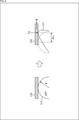
- FIG. 2 is an enlarged view showing a part of the fingertip portion 31.
- a in FIG. 2 shows the side surface of the fingertip portion 31, and B in FIG. 2 shows the front surface (inner surface) of the fingertip portion 31.
- a tactile sensor 24 is provided under the contact portion 23.
- a pressure distribution sensor capable of detecting the pressure at each position of the contact portion 23 is used.
- the contact portion 23 is made of an elastic material such as rubber, and forms a hemispherical flexible deformable layer.
- the fingertip portion 31A and the fingertip portion 31B have a parallel link mechanism.
- the fingertip portion 31A and the fingertip portion 31B are driven so that the inner surfaces are kept parallel.
- the object O which is the object to be gripped, is sandwiched between the contact portion 23A on the fingertip portion 31A side and the contact portion 23B on the fingertip portion 31B side arranged so that the inner surfaces are parallel to each other. It is gripped in such a way.
- the contact portion 23 that comes into contact with the object O will be deformed according to the gravity applied to the object O or the like.
- FIG. 4 is a diagram showing an example of the appearance of the robot to which the hand portion 1 is attached.
- the robot 41 to which the hand portion 1 is attached is a robot having a humanoid upper body and having a moving mechanism using wheels.
- a flat spherical head 52 is provided on the body portion 51.
- a visual sensor 52A composed of an RGB camera or the like is provided on the front surface of the head 52.
- Arm portions 2L and 2R which are manipulators with multiple degrees of freedom, are provided at the upper ends of the body portion 51.
- Hand portions 1L and 1R which are end effectors, are provided at the tips of the arm portions 2L and 2R, respectively.
- the hand portion 1L is the hand portion 1 which is the left hand of the robot 41
- the hand portion 1R is the hand portion 1 which is the right hand of the robot.
- a dolly-shaped moving body portion 53 is provided at the lower end of the body portion 51.
- the robot 41 can move by rotating the wheels provided on the left and right sides of the moving body portion 53 and changing the direction of the wheels.
- the robot 41 is a robot capable of performing various tasks such as grasping an object by the hand unit 1 and transporting the object while grasping the object.
- the arm portions 2L and 2R provided on the movable robot 41 are so-called mobile manipulators.
- An unknown object is an object whose characteristics such as mass, center of gravity position, friction coefficient, etc. are unknown.
- FIG. 5 is a diagram showing how the gripping object is arranged (placed).
- a horizontally long rectangular parallelepiped object O gripped by sandwiching the vicinity of the root with a fingertip portion 31 is brought into contact with the floor surface from the bottom surface of the tip, and the floor surface is shown in the lower part of FIG. I will explain the case of putting it in.
- the floor surface is the placement surface.
- FIG. 6 is a diagram showing a force acting on an object.
- Gravity mg acts on the object O as shown by arrow # 11. Further, by bringing the object O into contact with the floor surface, as shown by arrow # 12, the external force N acts as a normal force from the floor surface at the contact portion between the object O and the floor surface.
- a shear force FR acts as shown by arrow # 13
- a moment MR acts as shown by arrow # 14.
- l 1 is the distance from the gripping position to the center of gravity of the object O (distance between the perpendiculars passing through the respective positions). Further, l 2 is the distance from the gripping position to the position where the normal force acts (the distance between the perpendiculars passing through each position).
- the external moment which is the moment generated by the normal force from the floor surface, is expressed as Nl 2 .
- equation (1) is expressed as the equation (3).
- equation (2) is expressed as the equation (4).
- equations (3) and (4) the subscript i represents each finger.
- the slip generated in the object O is detected by using the slip sensation realized by the tactile sensor 24, and the external force N and the external moment Nl 2 are estimated based on the slip detection result.
- FIG. 7 is a diagram showing a model for explaining Hertz's contact theory.
- the elastic sphere 111 corresponds to the contact portion 23 of the hand portion 1
- the rigid flat plate 110 corresponds to the object O.
- FIG. 7 shows a state in which the rigid flat plate 110 is in horizontal contact with the elastic sphere 111.
- the right side of FIG. 7 shows a state in which a normal force f n is applied to the rigid flat plate 110 and a shear force ft is applied in the horizontal direction.
- the elastic sphere 111 is deformed in the direction of the shear force ft by applying the shear force ft.
- the position of the contact point between the rigid flat plate 110 and the elastic sphere 111 moves by the displacement amount ur from the position before the shearing force ft is applied.
- the displacement amount ur is the displacement amount generated at the fingertip portion 31 of the hand portion 1 in the robot 41.
- the displacement amount of the position generated at the fingertip portion 31 by applying a force corresponding to the shear force ft is referred to as a fingertip shear displacement amount ur .
- the amount of displacement in the rotational direction generated at the fingertip portion 31 is referred to as the amount of rotational displacement of the fingertip u theta .
- a force corresponding to a shearing force ft is applied, so that a displacement in the rotational direction also occurs.
- the fingertip shear displacement amount ur is expressed by Eq. (5) according to Hertz's contact theory.
- R is the radius of curvature of the elastic sphere 111.
- G * is the combined lateral elastic modulus of the elastic sphere 111 and the rigid plate 110, and E * is the combined Young's modulus of the elastic sphere 111 and the rigid plate 110.
- the radius of curvature R, the synthetic lateral elastic modulus G * , and the synthetic Young's modulus E * are physical information between the elastic sphere 111 and the rigid flat plate 110, and are constants.
- the fingertip shear displacement amount ur depends on the normal force f n and the shear force ft .
- the fingertip rotational displacement amount u theta is expressed by the equation (6).
- the fingertip rotational displacement amount u theta depends on the normal force f n and the moment M.
- FIG. 8 is a diagram showing an example in which an external force N acts on an object O and is applied to a model described with reference to FIG. 7.
- the normal force f n in FIG. 7 corresponds to the gripping force f nR .
- the shear force ft in FIG. 7 corresponds to the external force N.
- the moment M corresponds to the outer moment Nl 2 .
- the fingertip shear displacement amount ⁇ ur which is the fingertip shear displacement amount when an external force N acts on the object O
- the fingertip rotational displacement amount ⁇ u theta which is the fingertip rotational displacement amount when an external force N acts on the object O
- the equation (8) by modifying the equation (6).
- the fingertip shear displacement amount ⁇ ur depends on the gripping force f nR and the external force N. Since the gripping force f nR is known in the control unit that controls the gripping force of the hand unit 1, it is possible to estimate the external force N by observing the fingertip shear displacement amount ⁇ ur .
- the fingertip rotational displacement amount ⁇ u theta depends on the gripping force f nR and the outer moment Nl 2 . Since the gripping force f nR is known, it is possible to estimate the outer moment Nl 2 by observing the fingertip rotational displacement amount ⁇ u theta .
- the fingertip shear displacement amount ⁇ ur and the fingertip rotation displacement amount ⁇ u theta are observed based on the detection results by the tactile sensor 24. Further, the external force N is estimated based on the observation result of the fingertip shear displacement amount ⁇ ur , and the external moment Nl 2 is estimated based on the observation result of the fingertip rotation displacement amount ⁇ ur .
- the fingertip shear displacement amount ⁇ ur and the fingertip rotation displacement amount ⁇ u theta correspond to changes in the magnitude of slip of the elastic sphere 111 with respect to the rigid flat plate 110 (for example, changes per unit time).
- the fingertip shear displacement amount ⁇ ur and the fingertip rotation displacement amount ⁇ u theta are values indicating the degree of slippage of the elastic sphere 111 with respect to the rigid flat plate 110, respectively.
- the slip shown in FIGS. 7 and 8 is a so-called initial slip because the absolute contact position moves while maintaining the relative positional relationship between the contact positions of the elastic sphere 111 and the rigid flat plate 110. ..
- the slip detected based on the output of the tactile sensor 24 is slipping with the fixed portion (the portion where static friction is generated) on the contact surface between the contact portion 23 of the fingertip portion 31 and the gripped object. It is an initial slip in which a part (a part where dynamic friction is generated) is mixed.
- the external force N and the external moment Nl 2 are estimated using the initial slip.
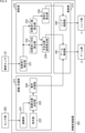
- FIG. 9 is a block diagram showing a configuration example of the information processing apparatus 201.
- the information processing device 201 is composed of a computer such as a PC.
- the computer constituting the information processing apparatus 201 is housed in, for example, the body portion 51.
- each functional unit shown in FIG. 9 is realized.
- the recognition / planning unit 211 As shown in FIG. 9, in the information processing apparatus 201, the recognition / planning unit 211, the calculation unit 212, and the control unit 213 are realized.
- the recognition / planning unit 211 is composed of a recognition unit 221, a command unit 222, an arrangement position determination unit 223, and an operation planning unit 224.
- Sensor data representing the detection result by the sensor unit 202 is input to the recognition unit 221.
- the sensor unit 202 includes sensors provided in each unit of the robot 41, including a visual sensor 52A.
- the sensor unit 202 includes various sensors such as an RGB camera, a distance sensor, a ToF sensor, a temperature sensor, a gyro sensor, and an acceleration sensor.
- the recognition unit 221 recognizes the environment around the robot 41 as well as the situation of the robot 41 based on the sensor data supplied from the sensor unit 202.
- the environment recognized by the recognition unit 221 includes the position and posture of the object to be gripped.
- the recognition result by the recognition unit 221 is supplied to the arrangement position determination unit 223.
- the command unit 222 determines the task to be executed by the robot 41, and outputs the information of the determined task to the arrangement position determination unit 223. For example, the task of placing the gripping object is determined.
- the arrangement position determination unit 223 determines the arrangement position of the gripped object based on the recognition result by the recognition unit 221 and the task determined by the command unit 222.
- the arrangement position determination unit 223 outputs information on the arrangement position of the gripped object to the motion planning unit 224.
- the motion planning unit 224 plans the operation of the arm unit 2 according to the arrangement position determined by the arrangement position determination unit 223 and the current position of the arm unit 2.
- the motion planning unit 224 outputs information regarding the operation of the arm unit 2 to the arm control unit 241.
- the calculation unit 212 is composed of an initial slip detection unit 231, an initial slip direction calculation unit 232, an initial slip amount calculation unit 233, a hand position / posture calculation unit 234, and a gripping force calculation unit 235.
- the initial slip detection unit 231, the initial slip direction calculation unit 232, and the initial slip amount calculation unit 233 are provided for each finger unit 12 corresponding to each finger unit 12.
- the initial slip detection unit 231 detects the initial slip based on the detection result of the pressure distribution by the tactile sensor 24 functioning as the slip sensor. For example, the initial slip detection unit 231 detects the movement of the center of pressure as the initial slip.
- the pressure center position X cop which is the position of the pressure center position in the X direction, is expressed by the equation (9).
- x i represents a position (X coordinate) in the X direction on the inner surface of the fingertip portion 31, and p (x i ) represents a pressure at the position x i .
- N represents the number of distributions. The pressure center position is similarly expressed in the Y direction.
- the initial slip detection unit 231 repeatedly detects the initial slip at a predetermined sampling cycle. Information on the pressure center position at each timing detected by the initial slip detection unit 231 is supplied to the initial slip direction calculation unit 232 and the initial slip amount calculation unit 233.
- the initial slip direction calculation unit 232 calculates the direction of change in the pressure center position as the initial slip direction based on the detection result by the initial slip detection unit 231. Information indicating the direction of the initial slip calculated by the initial slip direction calculation unit 232 is supplied to the hand position / posture calculation unit 234.
- the initial slip amount calculation unit 233 calculates the initial slip amount based on the detection result by the initial slip detection unit 231. For example, the initial slip amount calculation unit 233 calculates the amount of change (difference) in the pressure center position as the fingertip shear displacement amount ⁇ ur , and the amount of change in the rotation direction (angle direction) of the pressure center position is the fingertip rotation displacement amount ⁇ u. Calculated as theta .
- the calculation of the fingertip rotational displacement amount ⁇ u theta is performed, for example, based on the relative change amount of the plurality of pressure center positions detected by using the plurality of contact portions 23. Details of the calculation of the fingertip rotational displacement amount ⁇ u theta will be described later.
- the hand position / posture calculation unit 234 applies the fingertip shear displacement amount ⁇ ur calculated by the initial slip amount calculation unit 233 to the equation (7) to calculate (estimate) the magnitude of the external force N.
- the hand position / posture calculation unit 234 estimates the direction of the external force N based on the initial slip direction calculated by the initial slip direction calculation unit 232.
- the hand position / posture calculation unit 234 applies the fingertip rotation displacement amount ⁇ u theta calculated by the initial slip amount calculation unit 233 to the equation (8) to calculate the magnitude of the outer moment Nl 2 .
- the hand position / posture calculation unit 234 estimates the direction of the outer moment Nl 2 based on the initial slip direction calculated by the initial slip direction calculation unit 232.
- the hand position / posture calculation unit 234 functions as an estimation unit that estimates the magnitude and direction of the external force N and the magnitude and direction of the external moment Nl 2 , respectively.
- the hand position / posture calculation unit 234 calculates the position and posture of the fingertip unit 31 based on the estimated external force N and external moment Nl 2 . For example, in the hand position / posture calculation unit 234, the balance between the external force N and the force generated by the robot 41 is maintained, and the balance between the external moment Nl 2 and the moment generated by the robot 41 is maintained. The position and posture of 31 are calculated. Information on the position and posture of the fingertip unit 31 calculated by the hand position / posture calculation unit 234 is supplied to the arm control unit 241.
- the position and posture of the fingertip portion 31 corresponding to the hand of the robot 41 are controlled, but the position and posture of the finger portion 12 or the position and posture of the hand portion 1 is the position of the fingertip portion 31. It may be controlled instead of the posture, or the position and the posture may be controlled together with the position and the posture of the fingertip portion 31.
- the gripping force calculation unit 235 determines the magnitude of the external force N based on the fingertip shear displacement amount ⁇ ur and the fingertip rotation displacement amount ⁇ u theta calculated by the initial slip amount calculation unit 233. The magnitude of the outer moment Nl 2 is calculated.
- the gripping force calculation unit 235 calculates the gripping force f nR of the hand unit 1 based on the estimated external force N and the external moment Nl 2 . For example, in the gripping force calculation unit 235, the balance between the external force N and the force generated by the robot 41 is maintained, and the balance between the external moment Nl 2 and the moment generated by the robot 41 is maintained. The gripping force f nR is calculated.
- the gripping force f nR in which the balance between the external force N and the force generated by the robot 41 is maintained is, for example, so as to cancel the estimated external force N, that is, the observed fingertip shear displacement amount ⁇ ur becomes 0. It is calculated to. Further, the gripping force f nR that maintains the balance between the outer moment Nl 2 and the force generated by the robot 41 cancels, for example, the estimated outer moment Nl 2 , that is, the observed fingertip rotational displacement ⁇ u. It is calculated so that theta becomes 0.
- the information of the gripping force f nR estimated by the gripping force calculation unit 235 is supplied to the hand control unit 242.
- the control unit 213 is composed of an arm control unit 241 and a hand control unit 242.
- the arm control unit 241 controls the arm unit 2 according to the plan by the motion planning unit 224. Under the control of the arm control unit 241, the arm unit 2 moves to the vicinity of the position where the gripped object is arranged. Further, the arm control unit 241 controls the arm unit 2 according to the arm control algorithm.
- the arm control unit 241 controls the arm unit 2 so that the position and posture of the fingertip unit 31 are the positions and postures calculated by the hand position / posture calculation unit 234.
- the position and posture of the fingertip portion 31 are adjusted by the arm control algorithm so as to cancel the initial slip generated by the external force / moment, that is, the initial slip amount becomes zero. At least one of the position and the posture may be adjusted.
- the hand control unit 242 controls the gripping force f nR of the hand unit 1 according to the gripping force control algorithm.
- the hand control unit 242 controls the hand unit 1 and grips the gripping object with the gripping force f nR calculated by the gripping force calculation unit 235.
- step S1 the initial slip detection unit 231 detects the movement of the pressure center position as the initial slip based on the output of the tactile sensor 24.
- step S2 the initial slip direction calculation unit 232 calculates the initial slip direction based on the direction of movement of the pressure center position.
- step S3 the initial slip amount calculation unit 233 calculates the initial slip amount.
- the amount of change in the pressure center position is calculated as the fingertip shear displacement amount ⁇ ur
- the amount of change in the pressure center position in the rotational direction is calculated as the fingertip rotation displacement amount ⁇ ur .
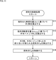
- step S4 the gripping force control process is performed.
- the gripping force control process the gripping force f nR of the hand unit 1 is controlled according to the gripping force control algorithm. The details of the gripping force control process will be described later with reference to the flowchart of FIG.
- step S5 arm control processing is performed.
- the operation of the arm portion 2 is controlled according to the arm control algorithm, and the position and posture of the fingertip portion 31 are adjusted. The details of the arm control process will be described later with reference to the flowchart of FIG.
- step S11 the gripping force calculation unit 235 applies the fingertip shear displacement amount ⁇ ur calculated by the initial slip amount calculation unit 233 to the equation (7) to calculate the magnitude of the external force N.
- step S12 the gripping force calculation unit 235 applies the fingertip rotation displacement amount ⁇ u theta calculated by the initial slip amount calculation unit 233 to the equation (8) to calculate the magnitude of the outer moment Nl 2 .
- the gripping force calculation unit 235 is a hand unit in which the balance between the external force N and the force generated by the robot 41 is maintained, and the balance between the external moment Nl 2 and the moment generated by the robot 41 is maintained.
- the gripping force f nR of 1 is calculated.
- step S14 the hand control unit 242 controls the hand unit 1 and grips the gripping object with the gripping force f nR calculated by the gripping force calculation unit 235. After that, the process returns to step S4 in FIG. 10 and the subsequent processing is performed.
- step S21 the hand position / posture calculation unit 234 applies the fingertip shear displacement amount ⁇ ur calculated by the initial slip amount calculation unit 233 to the equation (7) to calculate the magnitude of the external force N. Further, the hand position / posture calculation unit 234 calculates the direction of the external force N based on the direction of the initial slip calculated by the initial slip direction calculation unit 232.
- step S22 the hand position / posture calculation unit 234 applies the fingertip rotation displacement amount ⁇ u theta calculated by the initial slip amount calculation unit 233 to the equation (8) to calculate the magnitude of the outer moment Nl 2 . Further, the hand position / posture calculation unit 234 calculates the direction of the outer moment Nl 2 based on the direction of the initial slip calculated by the initial slip direction calculation unit 232.
- step S23 the hand position / posture calculation unit 234 maintains the balance between the external force N and the force generated by the robot 41, and also maintains the balance between the external moment Nl 2 and the moment generated by the robot 41.
- the position and posture of the fingertip portion 31 are calculated.
- step S24 the arm control unit 241 controls the arm unit 2 and adjusts the position and posture of the fingertip unit 31 so as to be the position and posture calculated by the hand position / posture calculation unit 234. After that, the process returns to step S5 in FIG. 10 and the subsequent processing is performed.
- the robot 41 can detect a minute change in the external force. Further, the robot 41 can arrange the object even when the arrangement operation is difficult, such as when the gripped object is soft or the environment of the arrangement destination is soft.
- the robot 41 stably arranges an unknown object by simultaneously performing gripping force control and arm control so that the balance between force and moment is maintained by using the slip information detected by the tactile sensor 24. Will be possible.
- the robot 41 may break the gripping object by applying an excessive force to the gripping object during the placement operation, or the force is too small to slide off. It is possible to prevent it from happening.
- the robot 41 can arrange the gripped object more stably.
- the fingertip rotational displacement amount ⁇ u theta is represented by the amount of change in the rotational direction of the pressure center position.
- the fingertip rotational displacement amount ⁇ u theta is calculated as follows.
- FIG. 13 is a diagram showing an arrangement example of the contact portion 23.
- a plurality of contact portions 23 are arranged on the inner surface of the fingertip portion 31 which is a contact surface with the gripping object.
- nine contact portions 23 of the contact portions 23-1 to 23-9 are arranged.
- a tactile sensor 24 is provided under the contact portions 23-1 to 23-9. The pressure distribution at the position corresponding to each of the contact portions 23-1 to 23-9 is detected by the tactile sensor 24.
- the fingertip rotational displacement amount ⁇ u theta is calculated based on the relative movement amount of a plurality of pressure center positions.
- FIG. 14 is a diagram showing changes in the state of the contact portion 23.
- FIG. 14 shows the states of the contact portions 23-1 to 23-3.
- x'copi and y'copi are the positions after rotation of the pressure center position of the contact portion 23-i in the X direction and the Y direction, respectively.
- the relationship between the pressure center position before and after rotation and the fingertip rotation displacement amount ⁇ u theta is expressed by Eq. (10) using the affine transformation.
- the fingertip rotational displacement amount ⁇ u theta is represented by a matrix of 3 rows and 3 columns on the left side of the equation (10).
- the same number of relationships represented by the equation (10) can be obtained as the number of contact portions 23.
- the fingertip rotational displacement amount ⁇ u theta can be obtained by approximating the fingertip rotational displacement amount ⁇ u theta when paying attention to each contact portion 23 by using the least squares method or the like.
- ⁇ u x represents the amount of change in the position of the pressure center position in the X direction.
- ⁇ u y represents the amount of change in the position of the pressure center position in the Y direction.
- FIG. 15 is a diagram showing an example of a change in the gripping posture.
- A, B, and C in FIG. 15 show changes in the gripping posture in the directions of the pitch axis, the roll axis, and the yaw axis, respectively.
- the gripping posture may change as shown in FIG. 15 due to contact with the floor surface.
- the initial slip direction and the total pressure value are calculated based on the detection results of the tactile sensors 24 provided on the fingertips 31 of the fingertips 12A of the left finger and the fingertips 12B of the right finger. Will be done.
- the total pressure value is the total value of the pressure detected at each position of the tactile sensor 24.
- the rotation axis of the inclination of the gripping object with respect to the floor surface (the rotation axis of the inclination of the gripping posture of the fingertip portion 31) is calculated based on the relationship between the initial sliding direction and the total pressure value.
- the posture of the object O can be adjusted and arranged.
- FIG. 16 is a diagram showing an example of adjusting the gripping posture.
- the posture of the object O is adjusted by adjusting the posture of the fingertip portion 31 in the pitch axis direction as shown in A of FIG.
- the posture of the fingertip portion 31 is adjusted in the roll axis direction and the yaw axis direction as shown in B and C of FIG. The posture of the object O is adjusted.
- FIG. 17 is a block diagram showing another configuration example of the information processing apparatus 201.
- FIG. 17 the same reference numerals are given to the same configurations as those described with reference to FIG. 9. Duplicate explanations will be omitted as appropriate.
- the configuration of the information processing apparatus 201 shown in FIG. 17 is the same as the configuration described with reference to FIG. 9, except that the hand posture rotation axis calculation unit 251 is additionally provided.
- the hand posture rotation axis calculation unit 251 calculates the rotation axis of the inclination of the fingertip unit 31, and outputs information indicating the rotation axis of the inclination to the hand position / posture calculation unit 234.
- the hand position / posture calculation unit 234 calculates the position and posture of the fingertip portion 31 so as to cancel the change in the position and posture due to the initial slip, in consideration of the rotation axis of the inclination calculated by the hand posture rotation axis calculation unit 251. Do it.
- the arm control unit 241 controls the arm unit 2 so that the position and posture of the fingertip unit 31 are the positions and postures calculated by the hand position / posture calculation unit 234.
- the control of the arm portion 2 is performed so as to adjust the position and posture of the fingertip portion 31 in the direction of the rotation axis calculated by the hand posture rotation axis calculation unit 251.
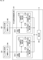
- FIG. 18 is a block diagram showing a configuration example of the hand posture rotation axis calculation unit 251.
- the hand posture rotation axis calculation unit 251 is composed of a left finger processing unit 261A, a right finger processing unit 261B, and a calculation unit 262.
- the left finger processing unit 261A is composed of an initial slip detection unit 271A, an initial slip direction calculation unit 272A, and a total pressure value calculation unit 273A.
- Sensor data representing the pressure distribution detected by the tactile sensor 24A provided on the finger portion 12A, which is the left finger, is supplied to the initial slip detection unit 271A and the total pressure value calculation unit 273A.
- the initial slip detection unit 271A detects the initial slip by calculating the amount of movement of the pressure center position based on the detection result of the pressure distribution by the tactile sensor 24A.
- the detection result by the initial slip detection unit 271A is supplied to the initial slip direction calculation unit 272A.
- the initial slip direction calculation unit 272A calculates the direction of change in the pressure center position as the initial slip direction based on the detection result by the initial slip detection unit 271A, and outputs information indicating the initial slip direction to the calculation unit 262. ..
- the total pressure value calculation unit 273A calculates the total pressure at each position of the tactile sensor 24A based on the detection result of the pressure distribution by the tactile sensor 24A, and outputs information indicating the total pressure value to the calculation unit 262.
- the right finger processing unit 261B is composed of an initial slip detection unit 271B, an initial slip direction calculation unit 272B, and a total pressure value calculation unit 273B.
- the same processing as the processing performed in the left finger processing unit 261A is based on the sensor data representing the pressure distribution detected by the tactile sensor 24B provided in the finger unit 12B which is the right finger. It will be done.
- the initial slip detection unit 271B detects the initial slip by calculating the amount of movement of the pressure center position based on the detection result of the pressure distribution by the tactile sensor 24B.
- the detection result by the initial slip detection unit 271B is supplied to the initial slip direction calculation unit 272B.
- the initial slip direction calculation unit 272B calculates the direction of change in the pressure center position as the initial slip direction based on the detection result by the initial slip detection unit 271B, and outputs information indicating the initial slip direction to the calculation unit 262. ..
- the total pressure value calculation unit 273B calculates the total pressure at each position of the tactile sensor 24B based on the detection result of the pressure distribution by the tactile sensor 24B, and outputs information indicating the total pressure value to the calculation unit 262.
- the initial slip detection unit 271A and the initial slip detection unit 271B can be realized by the initial slip detection unit 231 of FIG. Further, the initial slip direction calculation unit 272A and the initial slip direction calculation unit 272B can be realized by the initial slip direction calculation unit 232 of FIG.
- the calculation unit 262 rotates the inclination of the posture of the fingertip unit 31 based on the difference between the total pressure value calculated by the total pressure value calculation unit 273A and the total pressure value calculated by the total pressure value calculation unit 273B. Calculate the axis.
- the direction of the initial slip calculated by each of the initial slip direction calculation unit 272A and the initial slip direction calculation unit 272B is also taken into consideration.
- the direction of the initial slip the direction of the rotational force generated by the gripping object with respect to the fingertip portion 31 by the contact with the floor surface, that is, the axis of rotation is calculated.
- the information representing the rotation axis of the inclination of the posture of the fingertip unit 31 calculated by the calculation unit 262 is output to the hand position / posture calculation unit 234.
- the rotation axis of the posture tilt of the fingertip portion 31 is calculated, the posture tilt is canceled, and the arm control is performed so that the balance of force and moment is maintained as described above.
- the robot 41 can arrange and arrange the posture of the object even if the gripping state changes due to rotation due to the deviation of the center of gravity.
- the arm control based on the rotation axis of the posture of the fingertip portion 31 is not only for the task of arranging the gripped object, but also for other tasks such as the task of erasing the characters written on the whiteboard with a cleaner. Applicable.
- the posture information of each finger portion is used to calculate the rotation axis of the inclination of the posture of the fingertip portion 31. May be good.
- FIG. 19 is a block diagram showing another configuration example of the hand posture rotation axis calculation unit 251.
- the configuration of the hand posture rotation axis calculation unit 251 shown in FIG. 19 is that the finger processing unit 261 is provided in the same number as the number of finger units 12, and the posture information acquisition unit 281 is additionally provided. Except for the above, the configuration is the same as that described with reference to FIG.
- the posture information acquisition unit 281 calculates the posture of each finger based on the output of the encoder provided in the joint portion that is the movable part of each finger, and outputs the information indicating the posture of each finger to the calculation unit 262. Information indicating the amount of movement of the joint is output from the encoder provided at the joint of each finger.
- the calculation unit 262 considers the posture information of each finger in addition to the relationship between the initial slip direction and the total pressure value calculated based on the detection result by the tactile sensor 24 of each finger, and thereby grips the object with respect to the floor surface. Calculate the axis of rotation of the slope of.
- the information representing the rotation axis of the inclination of the posture of the fingertip unit 31 calculated by the calculation unit 262 is output to the hand position / posture calculation unit 234.
- ⁇ Other examples> ⁇ Sensor example Initial slip is detected based on the pressure distribution detected by the pressure distribution sensor, but the initial slip is detected using an optical system sensor such as an RGB camera or ToF sensor together with the pressure distribution sensor. The detection may be performed. When an optical system sensor is used in combination, for example, the deviation of each position of the contact portion 23, which is an elastic body, is measured by the optical system sensor.
- an optical system sensor such as an RGB camera or ToF sensor
- the initial slip may be detected by using a force sensor together with the pressure distribution sensor.
- the force sensor is used together, for example, the initial slip occurs when the magnitude of the force applied to the contact portion 23 becomes a preset magnitude as the magnitude of the force at the time of the occurrence of the initial slip. Detected as a thing.
- the motion planning information representing the operation of the arm unit 2 may be used.
- FIG. 20 is a diagram showing a configuration example of a control system.
- the control system shown in FIG. 20 is configured by providing the information processing device 201 as an external device of the robot 41. In this way, the information processing device 201 may be provided outside the housing of the robot 41.
- Various information such as information indicating the state of the robot 41 and information indicating the detection result of the sensor is transmitted from the robot 41 to the information processing device 201.
- Information for controlling the operation of the robot 41 is transmitted from the information processing device 201 to the robot 41.
- the robot 41 and the information processing device 201 may be directly connected as shown in FIG. 20A, or may be connected via a network such as the Internet as shown in FIG. 20B. May be good.
- the operation of the plurality of robots 41 may be controlled by one information processing device 201.
- the above-mentioned series of processes can be executed by hardware or software.
- the programs constituting the software are installed from a program recording medium on a computer embedded in dedicated hardware, a general-purpose personal computer, or the like.
- FIG. 21 is a block diagram showing a configuration example of computer hardware that executes the above-mentioned series of processes programmatically.
- the CPU Central Processing Unit
- ROM Read Only Memory
- RAM Random Access Memory
- An input / output interface 1005 is further connected to the bus 1004.
- An input unit 1006 including a keyboard, a mouse, and the like, and an output unit 1007 including a display, a speaker, and the like are connected to the input / output interface 1005.
- the input / output interface 1005 is connected to a storage unit 1008 including a hard disk and a non-volatile memory, a communication unit 1009 including a network interface, and a drive 1010 for driving the removable media 1011.
- the CPU 1001 loads the program stored in the storage unit 1008 into the RAM 1003 via the input / output interface 1005 and the bus 1004 and executes the above-mentioned series of processes. Is done.
- the program executed by the CPU 1001 is recorded on the removable media 1011 or provided via a wired or wireless transmission medium such as a local area network, the Internet, or digital broadcasting, and is installed in the storage unit 1008.
- a wired or wireless transmission medium such as a local area network, the Internet, or digital broadcasting
- the program executed by the computer may be a program in which processing is performed in chronological order according to the order described in the present specification, in parallel, or at a necessary timing such as when a call is made. It may be a program in which processing is performed.
- the system means a set of a plurality of components (devices, modules (parts), etc.), and it does not matter whether all the components are in the same housing. Therefore, a plurality of devices housed in separate housings and connected via a network, and a device in which a plurality of modules are housed in one housing are both systems. ..
- this technology can take a cloud computing configuration in which one function is shared by multiple devices via a network and processed jointly.
- each step described in the above flowchart can be executed by one device or shared by a plurality of devices.
- the plurality of processes included in the one step can be executed by one device or shared by a plurality of devices.
- a slip detection unit that detects slippage that occurs in an object that is being gripped by the fingers that make up the gripping unit, and a slip detection unit.
- An estimation unit that estimates the external force and moment applied to the object based on the slip generated on the object.
- An arm control unit that controls the operation of the arm portion based on the estimated external force and external moment, and adjusts at least one of the positions and postures of the finger portions constituting the grip portion provided on the arm portion. Information processing device equipped with.
- the information processing device which controls the arm portion so as to maintain a balance with the information processing device.
- the information processing apparatus according to (1) or (2), further comprising a gripping force control unit that controls the gripping force of the gripping portion based on the estimated external force and external moment.
- the gripping force control unit maintains a balance between the estimated external force and the force generated on the object by gripping the gripping portion, and is generated on the object by gripping the estimated external moment and the gripping portion.
- the information processing device which controls the gripping force so that the balance with the moment is maintained.
- the finger part An elastic body that comes into contact with the object when grasping the object, It has a pressure distribution sensor that detects the distribution of pressure applied to the elastic body.
- the slip detection unit detects any of the above (1) to (4) based on the detection result of the pressure distribution sensor, which detects the initial slip in which the fixed portion and the slip portion coexist between the object and the elastic body.
- the information processing device described in. (6) The information processing apparatus according to (5) above, wherein the estimation unit estimates the respective directions and amounts of an external force and an external moment applied to the object based on the direction and amount of the initial slip.
- the slip detection unit detects the initial slip based on the movement of the pressure center position.
- An initial slip direction calculation unit that calculates the direction of the initial slip based on the movement direction of the pressure center position
- the information processing apparatus according to (7) above, further comprising an initial slip amount calculation unit that calculates the initial slip amount based on the movement amount of the pressure center position.
- the information processing device according to any one of (1) to (8) above, wherein the slip detection unit detects slip generated on the object due to a drag force received from the placement surface when the object is placed.
- the slip detection unit is based on the deviation of each position of the elastic body detected by the sensor of the optical system, or based on the magnitude of the force applied to the elastic body detected by the force sensor.
- the information processing apparatus according to any one of (5) to (9) above, which detects the initial slip.
- the grip portion is provided with a plurality of the finger portions, and the grip portion is provided with a plurality of the finger portions.
- the information processing apparatus according to any one of (5) to (10), wherein the slip detection unit detects the initial slip in each finger based on the detection result of the pressure distribution sensor. (12) Further provided with a calculation unit that calculates the inclination of the finger portion that grips the object based on the direction of the initial slip and the force detected by the pressure distribution sensor of the finger portion.
- the information processing device according to (11), wherein the arm control unit controls the operation of the arm unit based on the calculated inclination.
- the external force and moment applied to the object are estimated.
- the operation of the arm portion is controlled based on the estimated external force and external moment, and a process of adjusting at least one of the positions and postures of the finger portions constituting the grip portion provided on the arm portion is executed. Program for.
- Calculation unit 234 hand position / posture calculation unit, 235 grip force calculation unit, 241 arm control unit, 242 hand control unit, 251 hand posture rotation axis calculation unit, 261A left finger processing unit, 261B right finger processing unit, 262 calculation unit , 271A, 271B initial slip detection unit, 272A, 272B initial slip direction calculation unit, 273A, 273B total pressure value calculation unit, 281 attitude information acquisition unit
Landscapes
- Engineering & Computer Science (AREA)
- Robotics (AREA)
- Mechanical Engineering (AREA)
- Human Computer Interaction (AREA)
- Health & Medical Sciences (AREA)
- General Health & Medical Sciences (AREA)
- Orthopedic Medicine & Surgery (AREA)
- Manipulator (AREA)
Abstract
Priority Applications (3)
| Application Number | Priority Date | Filing Date | Title |
|---|---|---|---|
| JP2022543886A JPWO2022039058A1 (fr) | 2020-08-20 | 2021-08-06 | |
| US18/005,856 US20240009857A1 (en) | 2020-08-20 | 2021-08-06 | Information processing device, information processing method, and program |
| CN202180056286.3A CN116113523A (zh) | 2020-08-20 | 2021-08-06 | 信息处理装置、信息处理方法和程序 |
Applications Claiming Priority (2)
| Application Number | Priority Date | Filing Date | Title |
|---|---|---|---|
| JP2020-139481 | 2020-08-20 | ||
| JP2020139481 | 2020-08-20 |
Publications (1)
| Publication Number | Publication Date |
|---|---|
| WO2022039058A1 true WO2022039058A1 (fr) | 2022-02-24 |
Family
ID=80322744
Family Applications (1)
| Application Number | Title | Priority Date | Filing Date |
|---|---|---|---|
| PCT/JP2021/029383 WO2022039058A1 (fr) | 2020-08-20 | 2021-08-06 | Dispositif de traitement d'informations, procédé de traitement d'informations, et programme |
Country Status (4)
| Country | Link |
|---|---|
| US (1) | US20240009857A1 (fr) |
| JP (1) | JPWO2022039058A1 (fr) |
| CN (1) | CN116113523A (fr) |
| WO (1) | WO2022039058A1 (fr) |
Cited By (2)
| Publication number | Priority date | Publication date | Assignee | Title |
|---|---|---|---|---|
| WO2023062941A1 (fr) * | 2021-10-15 | 2023-04-20 | ソニーグループ株式会社 | Dispositif de commande de préhension et procédé de commande de préhension |
| WO2024004622A1 (fr) * | 2022-06-29 | 2024-01-04 | ソニーグループ株式会社 | Robot et procédé de commande de robot |
Citations (8)
| Publication number | Priority date | Publication date | Assignee | Title |
|---|---|---|---|---|
| JP2005329512A (ja) * | 2004-05-20 | 2005-12-02 | Toyota Motor Corp | ロボットハンド指先力検出方法及び装置 |
| JP2009069028A (ja) * | 2007-09-13 | 2009-04-02 | Sony Corp | 検出装置および方法、プログラム、並びに記録媒体 |
| JP2011115924A (ja) * | 2009-12-07 | 2011-06-16 | Canon Inc | ロボットの把持装置 |
| JP2012228764A (ja) * | 2011-04-27 | 2012-11-22 | Hitachi Ltd | マニプレータ装置 |
| US20170036354A1 (en) * | 2015-08-03 | 2017-02-09 | Massachusetts Institute Of Technology | Two-Phase Gripper to Reorient and Grasp |
| JP2017087325A (ja) * | 2015-11-06 | 2017-05-25 | キヤノン株式会社 | ロボット制御装置、ロボット制御方法、ロボット制御システムおよびコンピュータプログラム |
| JP2019194534A (ja) * | 2018-05-01 | 2019-11-07 | 三井化学株式会社 | 検知部材、ロボットハンド、検知方法 |
| JP2020034425A (ja) * | 2018-08-30 | 2020-03-05 | トヨタ自動車株式会社 | センサシステム、ロボットハンド、センサシステムの較正方法、およびプログラム |
-
2021
- 2021-08-06 CN CN202180056286.3A patent/CN116113523A/zh active Pending
- 2021-08-06 JP JP2022543886A patent/JPWO2022039058A1/ja active Pending
- 2021-08-06 US US18/005,856 patent/US20240009857A1/en active Pending
- 2021-08-06 WO PCT/JP2021/029383 patent/WO2022039058A1/fr active Application Filing
Patent Citations (8)
| Publication number | Priority date | Publication date | Assignee | Title |
|---|---|---|---|---|
| JP2005329512A (ja) * | 2004-05-20 | 2005-12-02 | Toyota Motor Corp | ロボットハンド指先力検出方法及び装置 |
| JP2009069028A (ja) * | 2007-09-13 | 2009-04-02 | Sony Corp | 検出装置および方法、プログラム、並びに記録媒体 |
| JP2011115924A (ja) * | 2009-12-07 | 2011-06-16 | Canon Inc | ロボットの把持装置 |
| JP2012228764A (ja) * | 2011-04-27 | 2012-11-22 | Hitachi Ltd | マニプレータ装置 |
| US20170036354A1 (en) * | 2015-08-03 | 2017-02-09 | Massachusetts Institute Of Technology | Two-Phase Gripper to Reorient and Grasp |
| JP2017087325A (ja) * | 2015-11-06 | 2017-05-25 | キヤノン株式会社 | ロボット制御装置、ロボット制御方法、ロボット制御システムおよびコンピュータプログラム |
| JP2019194534A (ja) * | 2018-05-01 | 2019-11-07 | 三井化学株式会社 | 検知部材、ロボットハンド、検知方法 |
| JP2020034425A (ja) * | 2018-08-30 | 2020-03-05 | トヨタ自動車株式会社 | センサシステム、ロボットハンド、センサシステムの較正方法、およびプログラム |
Cited By (2)
| Publication number | Priority date | Publication date | Assignee | Title |
|---|---|---|---|---|
| WO2023062941A1 (fr) * | 2021-10-15 | 2023-04-20 | ソニーグループ株式会社 | Dispositif de commande de préhension et procédé de commande de préhension |
| WO2024004622A1 (fr) * | 2022-06-29 | 2024-01-04 | ソニーグループ株式会社 | Robot et procédé de commande de robot |
Also Published As
| Publication number | Publication date |
|---|---|
| JPWO2022039058A1 (fr) | 2022-02-24 |
| CN116113523A (zh) | 2023-05-12 |
| US20240009857A1 (en) | 2024-01-11 |
Similar Documents
| Publication | Publication Date | Title |
|---|---|---|
| JP6640792B2 (ja) | ハンド制御装置、ハンド制御方法、およびハンドのシミュレーション装置 | |
| JP5281377B2 (ja) | ロボット装置 | |
| JP6312264B2 (ja) | 冗長自由度を伴うロボットマニピュレータの制約 | |
| WO2022039058A1 (fr) | Dispositif de traitement d'informations, procédé de traitement d'informations, et programme | |
| US8060253B2 (en) | Systems and methods for controlling a legged robot based on rate of change of angular momentum | |
| JP4595727B2 (ja) | 外力推定システム及び外力推定方法、並びにコンピュータ・プログラム | |
| Dollar et al. | Joint coupling design of underactuated grippers | |
| JP6007636B2 (ja) | ロボット制御システム及びロボット制御装置 | |
| Yuan et al. | Design and control of roller grasper v2 for in-hand manipulation | |
| TWI827907B (zh) | 機器人的控制裝置、控制方法、機器人及其系統、學習裝置、方法及電腦程式產品 | |
| WO2008001713A1 (fr) | Robot articulé et son programme de commande | |
| Delgado et al. | In-hand recognition and manipulation of elastic objects using a servo-tactile control strategy | |
| JP2009269127A (ja) | 把持装置及びその制御方法 | |
| JP5406893B2 (ja) | 力および位置ベースの制御法則を用いたテンドン駆動ロボットフィンガのロバスト操作 | |
| Kazemi et al. | Human-inspired force compliant grasping primitives | |
| EP3862148A1 (fr) | Dispositif de traitement d'informations, procédé de commande, et programme | |
| JP6831530B2 (ja) | 外乱オブザーバ及びロボット制御装置 | |
| Costanzo | Control of robotic object pivoting based on tactile sensing | |
| JP6003312B2 (ja) | ロボットシステム | |
| Robson et al. | Kinematic synthesis and design of the robust closed loop articulated minimally actuated (clam) hand | |
| Koenig et al. | The role of tactile sensing in learning and deploying grasp refinement algorithms | |
| WO2020262058A1 (fr) | Dispositif de commande, procédé de commande et programme | |
| WO2021029205A1 (fr) | Dispositif de traitement d'informations, procédé de traitement d'informations, programme et robot | |
| JP2019084665A (ja) | ロボット制御装置、ロボット、ロボットシステム、及びプログラム | |
| Haschke | Grasping and manipulation of unknown objects based on visual and tactile feedback |
Legal Events
| Date | Code | Title | Description |
|---|---|---|---|
| 121 | Ep: the epo has been informed by wipo that ep was designated in this application |
Ref document number: 21858205 Country of ref document: EP Kind code of ref document: A1 |
|
| ENP | Entry into the national phase |
Ref document number: 2022543886 Country of ref document: JP Kind code of ref document: A |
|
| WWE | Wipo information: entry into national phase |
Ref document number: 18005856 Country of ref document: US |
|
| NENP | Non-entry into the national phase |
Ref country code: DE |
|
| 122 | Ep: pct application non-entry in european phase |
Ref document number: 21858205 Country of ref document: EP Kind code of ref document: A1 |