WO2022038783A1 - 結紮用デバイス - Google Patents
結紮用デバイス Download PDFInfo
- Publication number
- WO2022038783A1 WO2022038783A1 PCT/JP2020/031703 JP2020031703W WO2022038783A1 WO 2022038783 A1 WO2022038783 A1 WO 2022038783A1 JP 2020031703 W JP2020031703 W JP 2020031703W WO 2022038783 A1 WO2022038783 A1 WO 2022038783A1
- Authority
- WO
- WIPO (PCT)
- Prior art keywords
- cylinder
- slider
- joining member
- endoscope
- inner cylinder
- Prior art date
- Legal status (The legal status is an assumption and is not a legal conclusion. Google has not performed a legal analysis and makes no representation as to the accuracy of the status listed.)
- Ceased
Links
Images



Classifications
-
- A—HUMAN NECESSITIES
- A61—MEDICAL OR VETERINARY SCIENCE; HYGIENE
- A61B—DIAGNOSIS; SURGERY; IDENTIFICATION
- A61B17/00—Surgical instruments, devices or methods
- A61B17/12—Surgical instruments, devices or methods for ligaturing or otherwise compressing tubular parts of the body, e.g. blood vessels or umbilical cord
Definitions
- This disclosure relates to a ligation device.
- ligation devices for ligating affected areas such as diverticula and varicose veins formed in the gastrointestinal tract of patients.
- This type of ligation device is disclosed in, for example, Patent Document 1.
- the endoscope is fixed to the mounting cylinder fixed to the base end portion of the inner cylinder.
- the mounting cylinder is made of a material having appropriate flexibility and sealing property such as soft plastic or rubber.
- the present disclosure is intended to provide a ligation device that can be easily removed from the endoscope.
- the ligation device includes a first tubular body, a second tubular body connected to a base end portion of the first tubular body, and a second tubular body configured to be detachably attached to the tip end portion of the endoscope.
- a slider that has a tubular shape and is attached to the outer periphery of the first cylinder and is movable relative to the first cylinder along its major axis direction, and is attached to the outer periphery of the first cylinder.
- a ligation ring that is movable relative to the first cylinder together with the slider is provided, and the second cylinder has a fragile portion having a strength lower than that of other portions.
- the second cylinder is further provided with a tube that is at least partially joined to the fragile portion of the second cylinder and is configured to allow fluid to pass through the slider for relative movement, and the tube is pulled to pull the second cylinder. It may be configured so that a part of the second cylinder is broken by the fragile portion when the second cylinder is separated from the fragile portion.
- the fragile portion has a recess or a hole formed on the outer peripheral surface of the second cylinder along the long axis direction of the second cylinder, and the tube is formed along the recess or the hole. It may be arranged and fixed with a resin to the recess or the hole.
- the fragile portion has a slit formed along the long axis direction of the second cylinder, and the tube may be arranged along the slit and fixed to the slit by a resin.
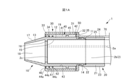
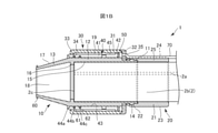
- FIG. 1A and 1B are vertical cross-sectional views showing a ligation device 1 attached to the endoscope 2 according to the present embodiment.
- FIG. 1A shows a state in which the slider 40, which will be described later, is located on the proximal end side
- FIG. 1B shows a state in which the slider 40 is advanced.
- FIGS. 1A and 1B show only the tip of the endoscope 2 to which the ligation device 1 is attached.
- the slider 40 only the slider piece 45 is shown.
- the appearance of the endoscope 2 is shown for convenience, and is not shown as a cross-sectional view (the same applies to the following views).
- the left side is the distal end side (distal side) inserted into the body, and the right side is the proximal end side (hand side, proximal side).
- the endoscope 2 is formed with a forceps hole 2a for inserting a forceps (not shown).
- the ligation device 1 has an inner cylinder 10, a joining member 20, an outer cylinder 30, a slider 40, a seal member 50, ligation rings 60, 61 and 62, and a tube 70.
- the inner cylinder 10 corresponds to the first cylinder
- the joining member 20 corresponds to the second cylinder.
- the inner cylinder 10 is located at the tip 2b of the endoscope and is attached to the tip 2b of the endoscope in an airtight state or a liquid-tight state.
- the inner cylinder 10 has a base end portion 11, an intermediate portion 12, and a tip end portion 13.
- the base end portion 11 is thinner than the intermediate portion 12 and has a smaller outer diameter.
- An annular convex portion 14 projecting outward is provided on the outer periphery of the base end portion 11.
- the intermediate portion 12 is located on the tip end side of the base end portion 11.
- An annular protrusion 16 projecting inward is provided on the inner peripheral surface 15 of the intermediate portion 12.
- the tip of the endoscope tip 2b abuts on the protrusion 16 in the long axis direction.
- the tip portion 13 is located on the tip end side of the intermediate portion 12.
- the tip portion 13 projects toward the tip side of the tip surface 2c of the endoscope 2.
- the tip portion 13 has a tapered shape that tapers toward the tip side, and has an inclined surface 17.
- a recessed space 18 is formed by the tip portion 13 and the tip surface 2c of the endoscope 2.
- the material constituting the inner cylinder 10 is not particularly limited, but is, for example, a metal material, a resin material, a ceramic material, or the like.
- metal materials include stainless steel, titanium and nickel-titanium alloys.
- the resin material include, for example, polyethylene, polypropylene, polyvinyl chloride, polystyrene, acrylic resin, phenol resin, melamine resin, polyimide, polyamide, polycarbonate, polyether sulfone, polyether ether ketone, polytetrafluoroethylene and the like.
- ceramic materials include, for example, glass or fine ceramics.
- the inner cylinder 10 As a material constituting the inner cylinder 10, since the ligation rings 60, 61 and 62 are attached to the inner cylinder 10 as described later, the inner cylinder 10 has strength to withstand it and has biocompatibility. It may be a thing. Further, as the material constituting the inner cylinder 10, a translucent material (for example, polypropylene, polycarbonate, polyether sulfone, polyimide, acrylic resin, etc.) may be used in order to maintain a wide field of view at the time of treatment.
- a translucent material for example, polypropylene, polycarbonate, polyether sulfone, polyimide, acrylic resin, etc.
- the joining member 20 is a member for fixing the ligation device 1 to the endoscope 2, and is attached to the outer periphery of the endoscope 2.
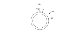
- FIG. 2 is an end view of the joining member 20 as viewed from the base end side.
- the joining member 20 has a cylindrical shape and is formed of an elastic material.
- the joining member 20 has a base end portion 21 and a tip end portion 22.
- the inner diameter of the joining member 20 is smaller than the outer diameter of the base end portion 11 of the inner cylinder 10.
- the tip portion 22 of the joining member 20 is attached to the base end portion 11 of the inner cylinder 10 in a state of being extended in the circumferential direction thereof. More specifically, in the joining member 20, the tip end portion 22 of the joining member 20 covers the outer periphery of the base end portion 11 of the inner cylinder body 10, and the base end portion 21 of the joining member 20 is the base of the inner cylinder body 10. It is attached to the base end portion 11 of the inner cylinder 10 in a state of being located closer to the base end portion 11 than the end portion 11.
- the endoscope 2 is inserted into the proximal end portion 21 and the inner tubular body 10 in a state where the proximal end portion 21 of the joining member 20 is extended. Therefore, the base end portion 21 of the joining member 20 is brought into close contact with the outer peripheral surface of the endoscope 2 by its elastic force, and the ligation device 1 is fixed to the endoscope 2.
- the joining member 20 is formed with a fragile portion 25 having a recess 24 having a substantially rectangular cross section extending in the long axis direction.
- the recess 24 is formed on the outer peripheral surface 23 of the joining member 20. Since the fragile portion 25 is thinner than the other parts of the joining member 20 in the cross section of the joining member 20, the strength of the fragile portion 25 is lower than the other parts of the joining member 20.
- a part of the tube 70 described later is inserted into the recess 24 along the recess 24 and fixed to the joining member 20 with an adhesive (resin). In other words, a part of the tube 70 is adhered (bonded) to the fragile portion 25.
- a part of the tube 70 may not be inserted into the recess 24, but may be arranged so as to cover the recess 24 and may be adhered to the fragile portion 25 with an adhesive (resin).
- the material constituting the joining member 20 is not particularly limited as long as it has strength and biocompatibility that can fix the ligation device 1 to the endoscope 2 so as not to come off, and is not particularly limited as described above.
- Natural rubber, synthetic rubber, thermoplastic elastomer and other elastic materials can be used.
- synthetic rubber include isoprene rubber, butadiene rubber, styrene / butadiene rubber, nitrile rubber, butyl rubber, ethylene / propylene rubber, acrylic rubber, fluororubber, silicone rubber and the like.
- thermoplastic elastomer examples include styrene-based elastomers, olefin-based elastomers, polyester-based elastomers, polyurethane-based elastomers, and polyamide-based elastomers.
- the adhesive is not particularly limited as long as the tube 70 has a strength and biocompatibility that does not separate from the fragile portion 25 when a tensile force is applied to the tube 70, and is not particularly limited, for example, an acrylic resin adhesive.
- acrylic resin adhesive examples thereof include urethane resin-based adhesives, epoxy resin-based adhesives, vinyl chloride resin solvent-based adhesives, cyanoacrylate-based adhesives, silicone-based adhesives, and phenol resin-based adhesives.
- the outer cylinder 30 has an outer cylinder portion 31 provided on the outer periphery of the intermediate portion 12 of the inner cylinder 10 and an outer cylinder lid 32.
- a slide space 19 is formed between the inner cylinder 10 and the outer cylinder 30.
- an annular convex portion 33 protruding inward is provided at the tip of the outer cylinder portion 31 at the tip of the outer cylinder portion 31, an annular convex portion 33 protruding inward is provided.
- the convex portion 33 and the intermediate portion 12 form an annular opening 34 through which the slide space 19 opens.
- the outer cylinder lid 32 is adhered to the base end portion of the outer cylinder portion 31 with an adhesive.
- the tip surface on the inner peripheral side of the outer cylinder lid 32 is fixed to the base end portion of the intermediate portion 12 of the inner cylinder body 10.
- the base end side of the slide space 19 is closed by the outer cylinder lid 32.
- the outer cylinder lid 32 is formed with a through hole 35 communicating with the slide space 19.
- the tip of the outer cylinder portion 31 is arranged at substantially the same position as the protrusion 16 of the inner cylinder body 10 in the long axis direction.
- the material constituting the outer cylinder 30 is not particularly limited as long as it has the strength to withstand the pressure of the fluid and biocompatibility as described later, and is, for example, the material exemplified as the material of the inner cylinder 10. Can be used.
- the material of the adhesive is not particularly limited as long as it has strength to withstand the pressure of the fluid and biocompatibility, and is the same as the adhesive for fixing the tube 70 to the joining member 20 described above. Adhesives can be used.
- the slider 40 has a cylindrical shape, is provided between the inner cylinder 10 and the outer cylinder 30, and is provided on the outer periphery of the inner cylinder 10 in an airtight or liquid-tight state along the inner cylinder in the longitudinal direction. It is mounted so that it can move relative to 10. Specifically, the slider 40 can slide on the outer peripheral surface of the intermediate portion 12 of the inner cylinder 10 toward the tip end portion 13 or the base end portion 11. The distance between the slider 40 and the inner cylinder 10 at the tip and / or base of the slider 40 is smaller than the thickness of the ligating rings 60, 61, and 62 described later. The length of the slider 40 in the major axis direction is substantially equal to that of the outer cylinder portion 31 of the outer cylinder 30.
- the slider 40 has a cylindrical portion 41 and a flange portion 42.
- Three annular grooves 44a, 44b, and 44c are formed at predetermined intervals along the major axis direction on the inner peripheral surface 43 of the tubular portion 41.
- the dimensions of the annular grooves 44a, 44b and 44c are configured to accommodate the ligation rings 60, 61 and 62 described below.
- the slider 40 moves relative to the inner cylinder 10 along the major axis direction, so that the annular grooves 44a, 44b and 44c of the slider 40 are at the tip from the slide space 19. Forward and backward to 13 are performed.
- the flange portion 42 abuts on the convex portion 33, and the slider 40 is prevented from coming out of the slide space 19.
- the slider 40 is composed of two slider pieces obtained by dividing a cylindrical slider 40 in half along a plane including a central axis extending in the major axis direction thereof. By adhering the slider pieces to each other with an adhesive, the two slider pieces are integrated to form the slider 40.
- the material constituting the slider 40 is not particularly limited as long as it has excellent slidability with the inner cylinder 10 and has biocompatibility, and the material exemplified as the material of the inner cylinder 10 is used. be able to.
- the material constituting the slider 40 may be a translucent material (for example, polypropylene, polycarbonate, polyether sulfone, polyimide, acrylic resin, etc.) in order to maintain a wide field of view during treatment.
- the material of the adhesive is not particularly limited as long as it has strength to withstand the pressure of the fluid and biocompatibility, and for example, the same adhesive as the above-mentioned adhesive can be used.
- the seal member 50 has an annular shape and is provided so as to be able to move along the major axis direction in the slide space 19 while abutting on the inner circumference of the outer cylinder portion 31 and the outer circumference of the inner cylinder 10. That is, the seal member 50 can move while sliding on the inner peripheral surface of the outer cylinder portion 31 and the outer peripheral surface of the inner cylinder 10. Further, the seal member 50 is fixed to the base end portion of the slider 40 so that it can move together with the slider 40. As a result, the space surrounded by the seal member 50, the outer cylinder lid 32, the inner cylinder body 10 and the outer cylinder portion 31 is airtightly maintained.
- the material constituting the sealing member 50 is not particularly limited as long as it enables airtightness of the space and has biocompatibility, and for example, the material exemplified as the material of the joining member 20 may be used. can.
- the ligating rings 60, 61 and 62 are O-rings, which are mounted on the outer periphery of the inner cylinder 10 and are located in the annular grooves 44a, 44b and 44c.
- the material is not particularly limited, and for example, the material exemplified as the material of the joining member 20 can be used.
- the materials constituting the ligation rings 60, 61 and 62 are, for example, gold, platinum, tungsten, an alloy containing these elements (for example, platinum-nickel alloy, etc.), barium sulfate, bismuth subcarbonate, trioxide.
- a radiation-impermeable material such as bismuth, bismuth oxychloride, or bismuth hypocarbonate, or a powder of these radio-impermeable materials may be contained.
- the vertical cross-sectional shape of the ligating rings 60, 61, and 62 (the shape that appears in the cross section of the inner cylinder 10 along the major axis direction when mounted on the outer circumference of the inner cylinder 10) is not limited to a circular shape, but is rectangular. Other shapes such as may be used.
- the color of the ligating rings 60, 61 and 62 is preferably a color such as black, which is distinct from the surrounding tissue.
- the tube 70 extends from the tip end portion to the base end portion along the endoscope 2.
- a syringe (not shown) for sending a gaseous fluid such as air to the slider 40 is connected to the base end of the tube 70.
- the tip of the tube 70 is airtightly connected to the base end of the through hole 35 of the outer cylinder lid 32. As described above, a part of the tip portion of the tube 70 is inserted into the recess 24 of the joining member 20 and adhered to the recess 24 with an adhesive.
- the material constituting the tube 70 is not particularly limited as long as it has flexibility and biocompatibility that can follow the deformation of the endoscope 2, and is, for example, polyethylene, polypropylene, polyvinyl chloride, or fluororesin. And so on.
- the endoscope 2 equipped with the ligation device 1 is inserted into the gastrointestinal tract and the inside of the gastrointestinal tract is observed.
- a bleeding diverticulum is identified, the endoscope 2 and the ligation device 1 are brought close to the diverticulum, the diverticulum is sucked through the forceps hole 2a, and the diverticulum becomes convex toward the endoscope 2.
- the diverticulum is positioned in the recessed space 18.
- a syringe (not shown) is operated to discharge the fluid through the tube 70 toward the slider 40.
- the fluid applies pressure to the base end side of the seal member 50 fixed to the base end portion of the slider 40, and advances the slider 40 and the seal member 50 using the pressure as a drive source.
- the fluid is accumulated in the space between the seal member 50, the outer cylinder portion 31, the intermediate portion 12 of the inner cylinder body 10, and the outer cylinder lid 32, which are formed as the slider 40 and the seal member 50 move forward.
- the slider 40 moves to the tip end side of the inner cylinder 10, and the ligation ring 60 located at the most advanced end moves to the tip end portion 13.
- the inclined surface 17 of the tip portion 13 is moved toward the tip side while the diameter of the ligation ring 60 is reduced, the diverticulum is separated from the tip portion 13, and the sucked diverticulum is ligated by the ligation ring 60.
- the endoscope 2 equipped with the ligation device 1 is taken out from the gastrointestinal tract. After that, the ligated diverticulum is necrotic and is discharged to the outside of the body together with the ligating ring 60.
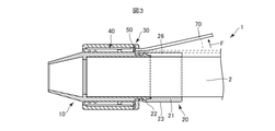
- FIG. 3 is an explanatory diagram of an operation of removing the ligation device 1 from the endoscope 2.
- FIG. 4 is an explanatory view of how the joining member 20 is torn.
- a tensile force F is applied to the tube 70 in a direction away from the ligation device 1 as shown in FIG. ,
- the fragile portion 25 is separated from the other portion of the joining member 20 and is torn off.
- a breaking slit 26 is formed in the portion corresponding to the fragile portion 25 of the joining member 20 along the long axis direction, and the joining state of the joining member 20 with respect to the endoscope 2 is released.
- the ligation device 1 can be easily removed from the endoscope 2.
- the ligation device 1 of the present embodiment since the joining member 20 has a fragile portion 25 having a strength lower than that of other portions, the ligation device 1 attached to the endoscope 2 is removed after its use. At that time, by breaking the joining member 20 through the fragile portion 25, the ligation device 1 can be easily removed from the endoscope 2. Therefore, the surgeon or the like can immediately start the next work and can efficiently proceed with the procedure.
- the fragile portion 25 is configured to break a part of the joining member 20, so that the joining member 20 is easily broken.
- the ligation device 1 can be easily removed from the endoscope 2.
- the recess 24 is formed on the outer peripheral surface 23 of the joining member 20 along the long axis direction of the joining member 20, and the tube 70 is arranged along the recess 24 and fixed to the recess 24 with resin. Has been done. Therefore, the joining member 20 can be reliably broken along the long axis direction, and the ligation device 1 can be easily removed from the endoscope 2.
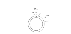
- the recess 24 of the fragile portion 25 has a substantially rectangular cross section, but as shown in FIG. 5A, the recess 24a has a substantially V-shaped cross section. It may be.
- the recess 24 of the fragile portion 25 is formed on the outer peripheral surface 23 of the joining member 20, but as shown in FIG. 5B, the recess 24b may be formed on the inner peripheral surface 27 of the joining member 20. Further, the recesses 24 (24a and 24b) may be formed on both the outer peripheral surface 23 and the inner peripheral surface 27.
- the concave portion 24 of the fragile portion 25 is formed from one end in the long axis direction of the joining member 20 to the entire other end, but as shown in FIGS. 6A, 6B and 6C, the fragile portion 25 is formed.
- the recess 24c may be formed only on the base end side
- the recess 24d may be formed only on the tip side
- the recess 24e may be formed only on the intermediate portion.
- a plurality of recesses may be formed at regular intervals along the major axis direction.
- the fragile portion 25 may be formed in a so-called perforation shape along the major axis direction at regular intervals with a plurality of holes penetrating the side surface of the joining member 20 instead of being composed of the recesses 24.
- the distance between the holes does not have to be constant.
- the fragile portion 25 was composed of the recess 24, but as shown in FIG. 7, it may be composed of the slit 28 extending along the long axis direction.
- the width of the slit 28 can be set as appropriate.
- the tube 70 is joined to the joining member 20 by, for example, the joining step shown in FIG. In FIG. 8, the upper row shows a top view of the joining member 20, and the lower row shows an end view of the joining member 20.
- the joining members 20 arranged one above the other are in the same step in the joining step, and the joining step proceeds in the order of (a) to (d).
- the slit 28 of the joining member 20 shown in FIG. 8A is filled with the adhesive 29A, and the slit 28 is closed with the adhesive 29A as shown in FIG. 8B.
- the tube 70 is arranged on the adhesive 29A along the major axis direction.
- the tube 70 is coated with the adhesive 29B, and the entire tube 70 is coated with the adhesives 29A and 29B. In this way, the tube 70 is joined to the joining member 20.
- the materials of the adhesives 29A and 29B are not particularly limited as long as they have biocompatibility, and the same adhesives as the above-mentioned adhesives can be used.
- the slit 28 is formed along the long axis direction of the joining member 20, the tube 70 is arranged along the slit 28, and is fixed to the slit 28 by the resin. That is, the fragile portion 25 is composed of a slit 28 and a resin member filled in the slit 28. Further, the tube 70 is joined (adhered) to this resin member. Therefore, the joining member 20 can be more reliably broken along the long axis direction, and the ligation device 1 can be easily removed from the endoscope 2.
- the tube 70 is adhered to the fragile portion 25, but as shown in FIG. 9, the fragile portion 25 and the tube 70 are arranged at different positions in the circumferential direction of the joining member 20 to form a tube.
- the structure may be such that the 70 is not adhered to the fragile portion 25. Therefore, in FIG. 9, only the fragile portion 25 is shown, and the tube 70 is not shown.
- the fragile portion 25 includes a resin layer 25A in its recess 24.
- the rear end portion 25B of the resin layer 25A projects rearward from the rear end portion of the joining member 20 and functions as a grip portion for the operator to grip.
- the fragile portion 25 may have a structure in which the slit 28 is provided with the resin layer 25A and the rear end portion 25B.
- the fluid for driving the slider 40 is a gas such as air, but may be a liquid such as physiological saline.
- a ring-shaped member made of a shape memory alloy can be used as the ligation ring. Since the shape of such a ring-shaped member changes from circular to non-circular when it is separated from the annular groove of the slider, ligation according to the shape of the affected portion becomes possible.
- a clip made of a shape memory alloy can also be used as the ligation ring. Such a clip is ring-shaped when it is housed in the annular groove of the slider, and when it is separated from the annular groove of the slider, its shape is deformed into a shape stored in advance.
- Ligature device 2 Endoscope 10: Inner cylinder 20: Bonding member 24, 24a, 24b, 24c, 24d, 24e: Recess 25: Vulnerable part 25A: Resin layer 25B: Rear end part 28: Slit 29A ⁇ 29B: Adhesive 40: Slits 60, 61, 62: Ligature ring 70: Tube
Landscapes
- Health & Medical Sciences (AREA)
- Surgery (AREA)
- Life Sciences & Earth Sciences (AREA)
- Heart & Thoracic Surgery (AREA)
- Molecular Biology (AREA)
- Vascular Medicine (AREA)
- Engineering & Computer Science (AREA)
- Biomedical Technology (AREA)
- Reproductive Health (AREA)
- Medical Informatics (AREA)
- Nuclear Medicine, Radiotherapy & Molecular Imaging (AREA)
- Animal Behavior & Ethology (AREA)
- General Health & Medical Sciences (AREA)
- Public Health (AREA)
- Veterinary Medicine (AREA)
- Surgical Instruments (AREA)
- Endoscopes (AREA)
Priority Applications (2)
| Application Number | Priority Date | Filing Date | Title |
|---|---|---|---|
| PCT/JP2020/031703 WO2022038783A1 (ja) | 2020-08-21 | 2020-08-21 | 結紮用デバイス |
| JP2022543254A JP7398570B2 (ja) | 2020-08-21 | 2020-08-21 | 結紮用デバイス |
Applications Claiming Priority (1)
| Application Number | Priority Date | Filing Date | Title |
|---|---|---|---|
| PCT/JP2020/031703 WO2022038783A1 (ja) | 2020-08-21 | 2020-08-21 | 結紮用デバイス |
Publications (1)
| Publication Number | Publication Date |
|---|---|
| WO2022038783A1 true WO2022038783A1 (ja) | 2022-02-24 |
Family
ID=80322879
Family Applications (1)
| Application Number | Title | Priority Date | Filing Date |
|---|---|---|---|
| PCT/JP2020/031703 Ceased WO2022038783A1 (ja) | 2020-08-21 | 2020-08-21 | 結紮用デバイス |
Country Status (2)
| Country | Link |
|---|---|
| JP (1) | JP7398570B2 (https=) |
| WO (1) | WO2022038783A1 (https=) |
Cited By (1)
| Publication number | Priority date | Publication date | Assignee | Title |
|---|---|---|---|---|
| JP2023147689A (ja) * | 2022-03-30 | 2023-10-13 | 朝日インテック株式会社 | 結紮用デバイス |
Citations (3)
| Publication number | Priority date | Publication date | Assignee | Title |
|---|---|---|---|---|
| JP2000014634A (ja) * | 1998-07-02 | 2000-01-18 | Olympus Optical Co Ltd | 内視鏡システム |
| JP2002253555A (ja) * | 2001-03-01 | 2002-09-10 | Sumitomo Bakelite Co Ltd | 連発式結紮用デバイス |
| WO2020013287A1 (ja) * | 2018-07-11 | 2020-01-16 | 朝日インテック株式会社 | 結紮用デバイス |
-
2020
- 2020-08-21 JP JP2022543254A patent/JP7398570B2/ja active Active
- 2020-08-21 WO PCT/JP2020/031703 patent/WO2022038783A1/ja not_active Ceased
Patent Citations (3)
| Publication number | Priority date | Publication date | Assignee | Title |
|---|---|---|---|---|
| JP2000014634A (ja) * | 1998-07-02 | 2000-01-18 | Olympus Optical Co Ltd | 内視鏡システム |
| JP2002253555A (ja) * | 2001-03-01 | 2002-09-10 | Sumitomo Bakelite Co Ltd | 連発式結紮用デバイス |
| WO2020013287A1 (ja) * | 2018-07-11 | 2020-01-16 | 朝日インテック株式会社 | 結紮用デバイス |
Cited By (1)
| Publication number | Priority date | Publication date | Assignee | Title |
|---|---|---|---|---|
| JP2023147689A (ja) * | 2022-03-30 | 2023-10-13 | 朝日インテック株式会社 | 結紮用デバイス |
Also Published As
| Publication number | Publication date |
|---|---|
| JP7398570B2 (ja) | 2023-12-14 |
| JPWO2022038783A1 (https=) | 2022-02-24 |
Similar Documents
| Publication | Publication Date | Title |
|---|---|---|
| JP7436447B2 (ja) | 内視鏡用の使い捨ての吸引バルブ | |
| US7736302B2 (en) | Cap for endoscope | |
| US7645230B2 (en) | Over-tube, method of manufacturing over-tube, method of disposing over-tube, and method of treatment in abdominal cavity | |
| JP5959770B2 (ja) | 内視鏡の先端構造 | |
| JP2021115364A (ja) | バルーンカテーテル | |
| JP5352579B2 (ja) | 留置針組立体 | |
| JP2002017665A (ja) | 内視鏡用器具 | |
| JP2009183460A (ja) | 痔核結紮具およびこれを含む結紮用キット | |
| WO2022038783A1 (ja) | 結紮用デバイス | |
| JP6165386B2 (ja) | 挿入機器の先端カバー及び挿入機器 | |
| JP7118150B2 (ja) | 結紮用デバイス | |
| JP7118151B2 (ja) | 結紮用デバイス | |
| JP5903875B2 (ja) | 内視鏡用注射針 | |
| JP4009599B2 (ja) | 内視鏡用処置具栓 | |
| WO2021059943A1 (ja) | バルーンカテーテル | |
| JP2004000430A (ja) | 挿入用外套管 | |
| JP3765730B2 (ja) | 連発式結紮用デバイス | |
| JP3992820B2 (ja) | 内視鏡の鉗子栓 | |
| JPH09131399A (ja) | 内視鏡用穿刺針 | |
| JP2025083867A (ja) | 結紮用デバイス | |
| JP2004290488A (ja) | 穿刺吸引装置 | |
| JP2023147689A (ja) | 結紮用デバイス | |
| JP4311996B2 (ja) | 内視鏡用処置具 | |
| JP2001037768A (ja) | 超音波処置装置 | |
| JP2024068003A (ja) | 結紮装置 |
Legal Events
| Date | Code | Title | Description |
|---|---|---|---|
| 121 | Ep: the epo has been informed by wipo that ep was designated in this application |
Ref document number: 20950348 Country of ref document: EP Kind code of ref document: A1 |
|
| ENP | Entry into the national phase |
Ref document number: 2022543254 Country of ref document: JP Kind code of ref document: A |
|
| NENP | Non-entry into the national phase |
Ref country code: DE |
|
| 122 | Ep: pct application non-entry in european phase |
Ref document number: 20950348 Country of ref document: EP Kind code of ref document: A1 |