WO2022038731A1 - 温度測定装置 - Google Patents
温度測定装置 Download PDFInfo
- Publication number
- WO2022038731A1 WO2022038731A1 PCT/JP2020/031389 JP2020031389W WO2022038731A1 WO 2022038731 A1 WO2022038731 A1 WO 2022038731A1 JP 2020031389 W JP2020031389 W JP 2020031389W WO 2022038731 A1 WO2022038731 A1 WO 2022038731A1
- Authority
- WO
- WIPO (PCT)
- Prior art keywords
- fabry
- light
- measuring device
- incident surface
- temperature
- Prior art date
- Legal status (The legal status is an assumption and is not a legal conclusion. Google has not performed a legal analysis and makes no representation as to the accuracy of the status listed.)
- Ceased
Links
Images


Classifications
-
- G—PHYSICS
- G01—MEASURING; TESTING
- G01K—MEASURING TEMPERATURE; MEASURING QUANTITY OF HEAT; THERMALLY-SENSITIVE ELEMENTS NOT OTHERWISE PROVIDED FOR
- G01K1/00—Details of thermometers not specially adapted for particular types of thermometer
- G01K1/20—Compensating for effects of temperature changes other than those to be measured, e.g. changes in ambient temperature
- G01K1/24—Compensating for effects of temperature changes other than those to be measured, e.g. changes in ambient temperature by means of compounded strips or plates, e.g. by bimetallic strips
-
- G—PHYSICS
- G01—MEASURING; TESTING
- G01J—MEASUREMENT OF INTENSITY, VELOCITY, SPECTRAL CONTENT, POLARISATION, PHASE OR PULSE CHARACTERISTICS OF INFRARED, VISIBLE OR ULTRAVIOLET LIGHT; COLORIMETRY; RADIATION PYROMETRY
- G01J5/00—Radiation pyrometry, e.g. infrared or optical thermometry
- G01J5/38—Radiation pyrometry, e.g. infrared or optical thermometry using extension or expansion of solids or fluids
- G01J5/44—Radiation pyrometry, e.g. infrared or optical thermometry using extension or expansion of solids or fluids using change of resonant frequency, e.g. of piezoelectric crystals
-
- G—PHYSICS
- G01—MEASURING; TESTING
- G01J—MEASUREMENT OF INTENSITY, VELOCITY, SPECTRAL CONTENT, POLARISATION, PHASE OR PULSE CHARACTERISTICS OF INFRARED, VISIBLE OR ULTRAVIOLET LIGHT; COLORIMETRY; RADIATION PYROMETRY
- G01J3/00—Spectrometry; Spectrophotometry; Monochromators; Measuring colours
- G01J3/02—Details
- G01J3/0286—Constructional arrangements for compensating for fluctuations caused by temperature, humidity or pressure, or using cooling or temperature stabilization of parts of the device; Controlling the atmosphere inside a spectrometer, e.g. vacuum
-
- G—PHYSICS
- G01—MEASURING; TESTING
- G01J—MEASUREMENT OF INTENSITY, VELOCITY, SPECTRAL CONTENT, POLARISATION, PHASE OR PULSE CHARACTERISTICS OF INFRARED, VISIBLE OR ULTRAVIOLET LIGHT; COLORIMETRY; RADIATION PYROMETRY
- G01J3/00—Spectrometry; Spectrophotometry; Monochromators; Measuring colours
- G01J3/12—Generating the spectrum; Monochromators
- G01J3/26—Generating the spectrum; Monochromators using multiple reflection, e.g. Fabry-Perot interferometer, variable interference filters
-
- G—PHYSICS
- G01—MEASURING; TESTING
- G01K—MEASURING TEMPERATURE; MEASURING QUANTITY OF HEAT; THERMALLY-SENSITIVE ELEMENTS NOT OTHERWISE PROVIDED FOR
- G01K11/00—Measuring temperature based upon physical or chemical changes not covered by groups G01K3/00, G01K5/00, G01K7/00 or G01K9/00
-
- G—PHYSICS
- G01—MEASURING; TESTING
- G01K—MEASURING TEMPERATURE; MEASURING QUANTITY OF HEAT; THERMALLY-SENSITIVE ELEMENTS NOT OTHERWISE PROVIDED FOR
- G01K11/00—Measuring temperature based upon physical or chemical changes not covered by groups G01K3/00, G01K5/00, G01K7/00 or G01K9/00
- G01K11/12—Measuring temperature based upon physical or chemical changes not covered by groups G01K3/00, G01K5/00, G01K7/00 or G01K9/00 using changes in colour, translucency or reflectance
- G01K11/125—Measuring temperature based upon physical or chemical changes not covered by groups G01K3/00, G01K5/00, G01K7/00 or G01K9/00 using changes in colour, translucency or reflectance using changes in reflectance
Definitions
- the present invention relates to a temperature measuring device.
- the temperature measurement inside the incinerator first of all, it is required to be able to use it stably even in a high temperature environment. It is also required that this type of temperature measurement is less susceptible to combustion products such as soot. In addition, this type of temperature measurement is also required to be able to keep up with the ever-changing temperature changes in the furnace. In addition, this kind of temperature measurement is also required to be able to measure the temperature distribution in the furnace. There are technical issues to meet these requirements, and performance improvement of this type of temperature measuring device is still being considered.
- thermocouple thermometer the probe unit and the measurement unit are generally connected by an electric cable. If the high-temperature part that is the measurement area covers a wide area, the electric cable will be installed in a high-temperature environment. In such a case, it is necessary to protect the electric cable from a high temperature environment, and there is a problem that the equipment becomes complicated.
- the radiation thermometer the equipment is not complicated due to the installation of cables as described above.
- the emissivity of the radiation energy differs depending on the substance, so it is adjusted to the object of temperature measurement. There is a problem that it is not easy to measure the temperature of the object accurately because it requires calibration.
- the present invention has been made to solve the above problems, and an object of the present invention is to make it easier and more accurate to measure the temperature without complicating the equipment.
- the temperature measuring device includes a first incident surface and a first emission surface arranged on the opposite side of the first incident surface, and is composed of a material having an electrostrictive effect and transmitting light. It is provided with a plate-shaped first component in which one incident surface and a first emission surface are arranged on an optical axis, and a second emission surface arranged on a side opposite to the second incident surface and the second incident surface. A plate-like material in which the second incident surface and the second exit surface are arranged on the optical axis, and the distance between the first incident surface and the second incident surface is constant on the optical axis.
- the temperature of the measurement environment in which the Fabry-Perot interferometer is placed is obtained by observing the light transmitted through the Fabry-Perot interferometer, so that the equipment is not complicated. Accurate temperature can be measured more easily.
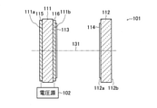
- This temperature measuring device includes a Fabry-Perot interferometer 101, a power supply 102, and a light source 103. This temperature measuring device obtains the temperature of the measurement environment in which the Fabry-Perot interferometer 101 is arranged by observing the light emitted from the light source 103 and transmitted through the Fabry-Perot interferometer 101.
- the Fabry-Perot interferometer 101 includes a plate-shaped first component 111, a plate-shaped second component 112, a first reflective film 113, a second reflective film 114, and a first electrode 115. And the second electrode 116.
- the first component 111 includes a first incident surface 111a and a first exit surface 111b arranged on the side opposite to the first incident surface 111a. Further, the first component 111 is made of a material having an electrostrain effect and transmitting light. The first component 111 can be made of, for example, a piezoelectric crystal having an electrostrain effect. The first component 111 is made of a material having high transparency to light 121 and light 122 in the wavelength band emitted from the light source 103.
- the material constituting the first component 111 having an electrostrictive effect and transmitting light is, for example, KTN [KTa 1- ⁇ Nb ⁇ O 3 (0 ⁇ ⁇ 1)] crystals or KLTN [KLTN] to which lithium is added. It can be composed of any of K 1- ⁇ Li ⁇ Ta 1- ⁇ Nb ⁇ O 3 (0 ⁇ ⁇ 1,0 ⁇ ⁇ 1)] crystals. KTN crystals and KLTN crystals are known as crystals having an electrostrain effect. It is known that the electric strain effect of these crystals can obtain a strain amount proportional to the square of the electric field defined by the voltage / distance between electrodes.
- the material constituting the first component 111 which has an electrostrictive effect and allows light to pass through, is composed of barium titanate (BaTIO 3 ), lithium niobate (LiNbO 3 ), calcium fluoride (CaF 2 ), and the like. You can also do it. It is important that the surface accuracy (maximum shape error) of the first incident surface 111a and the first emitting surface 111b of the first component 111 is about the wavelength of the target light / 10.
- the second component 112 includes a second incident surface 112a and a second exit surface 112b arranged on the side opposite to the second incident surface 112a. Further, the second component 112 is made of a material through which light is transmitted. The second component 112 can be made of a material having high transparency to light in the target wavelength band. The second component 112 can be made of, for example, BK7 glass or quartz glass.
- the first incident surface 111a and the first emitting surface 111b of the first component 111 are arranged on the optical axis (optical path) 131, and both the second incident surface 112a and the second emitting surface 112b of the second component 112 are arranged. It is arranged on the optical axis 131. Further, the distance between the first incident surface 111a and the second incident surface 112a is fixed on the optical axis 131. For example, if the first component 111 and the second component 112 are fixedly arranged on a surface plate (not shown), the distance between the first incident surface 111a and the second incident surface 112a can be fixed on the optical axis 131. can.
- the Fabry-Perot interferometer 101 is formed on a first reflecting film 113 formed on the first emitting surface 111b and partially reflecting light, and a second reflecting film 113 formed on the second incident surface 112a and partially reflecting light.
- a reflective film 114 is provided.
- the Fabry-Perot interferometer is composed of the first reflective film 113 and the second reflective film 114.
- first exit surface 111b and the second incident surface 112a are arranged so as to face each other and can be in a parallel relationship with each other. Further, the first incident surface 111a and the first emitting surface 111b can be in a parallel relationship with each other. Similarly, the second incident surface 112a and the second exit surface 112b can be in a parallel relationship with each other.
- the first exit surface 111b and the second incident surface 112a face each other. There is no need to place the position.
- the first exit surface 111b and the second incident surface 112a can be planes perpendicular to the optical axis 131.
- the positional relationship between the first emission surface 111b and the second incident surface 112a described above is synonymous with the relationship between the reflection surface of the first reflection film 113 and the reflection surface of the second reflection film 114.
- the power supply 102 supplies a voltage for applying an electric field to the first component 111.
- the Fabry-Perot interferometer 101 includes a first electrode 115 and a second electrode 116 for applying an electric field to the first component 111, and a power supply 102 is connected to the first electrode 115 and the second electrode 116.
- the first electrode 115 is formed on the first incident surface 111a
- the second electrode 116 is formed between the first emitting surface 111b and the first reflecting film 113.
- the first electrode 115 and the second electrode 116 are transparent electrodes.
- the first electrode 115 and the second electrode 116 can be made of, for example, indium tin oxide (ITO).
- the distance between the first electrode 115 and the second electrode 116 in other words, the plate thickness of the first component 111 is smaller than the beam diameters of the light 121 and the light 122.
- the distance (distance) between the first electrode 115 and the second electrode 116 is 0.1 mm, and the distance between the reflective surface of the first reflective film 113 and the reflective surface of the second reflective film 114. (Distance on the optical axis) can be 10 ⁇ m, and the reflectance of the first reflective film 113 and the second reflective film 114 can be 99.5%.
- the light source 103 emits light 121 and light 122 to the Fabry-Perot interferometer 101.
- the light source 103 emits a plurality of lights 121 and 122 having different wavelengths from each other, and the color of the light transmitted through the Fabry-Perot interferometer 101 determines the measurement environment in which the Fabry-Perot interferometer 101 is arranged. Find the temperature.
- a KTN crystal is known as a crystal having an electric strain effect, and by applying an electric field to the crystal, strain proportional to the square of the electric field can be obtained.
- the relationship between the strain and the electric field is represented by "S to Q ⁇ 2 E 2 ... (1)".
- S is a strain
- Q is an electrostrain coefficient
- ⁇ is a dielectric constant
- E is an electric field.
- the strain of the KTN crystal is proportional to the square of the electric field and proportional to the square of the permittivity.
- FIG. 2 shows the relationship between the temperature of the KTN crystal and the relative permittivity.
- the permittivity has a temperature dependence with the Curie temperature (Tc) as the peak. It is known that the Curie temperature can be changed from ⁇ 100 ° C. to + 400 ° C. by changing the composition of crystals. From this, it can be seen that the strain of the KTN crystal changes depending on the temperature.
- the relative permittivity of a material having an electrostrain effect changes with a change in temperature.
- the Fabry-Perot interferometer 101 transmits only light having a wavelength corresponding to the resonator length, which is the distance between the first reflecting film 113 and the second reflecting film 114, by forming a resonator structure. .. Therefore, the transmission wavelength is changed by changing the resonator length.
- the temperature of the first component 111 having the electric strain effect reflects the change in the environmental temperature, and the specific dielectric constant changes according to the temperature change.
- the transmission wavelength of the Fabry-Perot interferometer 101 changes.
- the environmental temperature can be obtained by, for example, visually observing the light transmitted through the Fabry-Perot interferometer 101 whose transmission wavelength changes in response to a change in the environmental temperature.
- the first embodiment by using visible light as the light source, it is possible to obtain the difference in temperature without the need for a special light receiver.
- the Fabry-Perot interferometer 101 having the first component 111 made of a KTN crystal plate having a drive voltage of 500 V and a plate thickness of 1 mm by the power supply 102 has a resonator length of 532 nm at 40 ° C.
- a red laser (light 121) having a wavelength of 650 nm and a green laser (light 122) having a wavelength of 532 nm are used as the light source 103.
- the temperature of the environment in which the Fabry-Perot interferometer 101 is arranged changes from 40 ° C. to 42 ° C.
- the wavelength of the light transmitted through the Fabry-Perot interferometer 101 changes from red to green.
- the temperature of the environment in which the Fabry-Perot interferometer 101 is placed can be obtained (measured).
- the strain (resonator length) is proportional to the square of the electric field, so by increasing the voltage (driving voltage) supplied from the power supply 102, the Fabry-Perot can be used. It is possible to increase the change in the resonator length of the interferometer 101.
- the Fabry-Permittivity Interferometer 101 in which the first component 111 is composed of a KTN crystal plate having a plate thickness of 1 mm, when the drive voltage is 1000 V, the relative permittivity changes from 20000 to 19500 even though the resonator length changes by about 130 nm. Just let me do it.
- the drive voltage is increased, the same wavelength change as described above can be confirmed with a smaller temperature change. This means that the sensitivity to temperature changes is improved. By changing the drive voltage in this way, it is possible to adjust the temperature to be measured.
- the temperature measuring device includes a Fabry-Perot interferometer 101, a power supply 102, a light source 103a, and a measuring device 104.
- This temperature measuring device measures (observes) the light emitted from the light source 103 and transmitted through the Fabry-Perot interferometer 101 with the measuring instrument 104 to obtain the temperature of the measurement environment in which the Fabry-Perot interferometer 101 is arranged. ..
- the measuring instrument 104 measures the wavelength of the light transmitted through the Fabry-Perot interferometer 101.
- the measuring instrument 104 can be composed of a well-known spectroscope.
- the measured wavelength of light is displayed, for example, on a display (not shown).
- the environmental temperature can be obtained by checking the numerical value of the wavelength displayed on the display.
- the light source 103a emits light in the infrared region used for the communication wavelength band. In this case, the light transmitted through the Fabry-Perot interferometer 101 cannot be visually confirmed, but the wavelength of the light is measured by being separated by the measuring instrument 104, and this value is shown, so that the difference in wavelength is confirmed. be able to.
- the light source 103a may be configured to emit light including a plurality of wavelengths such as white light. In this way, by using a light source that emits light having continuous wavelengths, it is possible to continuously acquire the value of the temperature change.
- the temperature of the measurement environment in which the Fabry-Perot interferometer is placed is obtained by observing the light transmitted through the Fabry-Perot interferometer, so that the equipment is not complicated. , It will be possible to measure the temperature more easily and accurately.
- 101 ... Fabry-Perot interferometer, 102 ... power supply, 103 ... light source, 121 ... light, 122 ... light.
Landscapes
- Physics & Mathematics (AREA)
- General Physics & Mathematics (AREA)
- Spectroscopy & Molecular Physics (AREA)
- Chemical & Material Sciences (AREA)
- Crystallography & Structural Chemistry (AREA)
- Measuring Temperature Or Quantity Of Heat (AREA)
Priority Applications (3)
| Application Number | Priority Date | Filing Date | Title |
|---|---|---|---|
| US18/006,823 US20230280214A1 (en) | 2020-08-20 | 2020-08-20 | Temperature Measurement Device |
| PCT/JP2020/031389 WO2022038731A1 (ja) | 2020-08-20 | 2020-08-20 | 温度測定装置 |
| JP2022543210A JPWO2022038731A1 (https=) | 2020-08-20 | 2020-08-20 |
Applications Claiming Priority (1)
| Application Number | Priority Date | Filing Date | Title |
|---|---|---|---|
| PCT/JP2020/031389 WO2022038731A1 (ja) | 2020-08-20 | 2020-08-20 | 温度測定装置 |
Publications (1)
| Publication Number | Publication Date |
|---|---|
| WO2022038731A1 true WO2022038731A1 (ja) | 2022-02-24 |
Family
ID=80323504
Family Applications (1)
| Application Number | Title | Priority Date | Filing Date |
|---|---|---|---|
| PCT/JP2020/031389 Ceased WO2022038731A1 (ja) | 2020-08-20 | 2020-08-20 | 温度測定装置 |
Country Status (3)
| Country | Link |
|---|---|
| US (1) | US20230280214A1 (https=) |
| JP (1) | JPWO2022038731A1 (https=) |
| WO (1) | WO2022038731A1 (https=) |
Citations (6)
| Publication number | Priority date | Publication date | Assignee | Title |
|---|---|---|---|---|
| JPS57190214A (en) * | 1981-05-20 | 1982-11-22 | Toshiba Corp | Optical sensor device |
| JPH0280903A (ja) * | 1988-09-17 | 1990-03-22 | Rion Co Ltd | 物理量測定装置 |
| JP2008107141A (ja) * | 2006-10-24 | 2008-05-08 | Institute Of National Colleges Of Technology Japan | リング共振器とブラッググレーティングを用いた光波長検波型物理量計測センサ |
| JP2015117421A (ja) * | 2013-12-19 | 2015-06-25 | Fdk株式会社 | ウエッジ膜の形成方法 |
| JP2015520868A (ja) * | 2012-05-08 | 2015-07-23 | テクノロジアン・トゥトキムスケスクス・ブイティティー | ファブリー・ペロー干渉計およびその製造方法 |
| US20180188116A1 (en) * | 2016-04-14 | 2018-07-05 | Halliburton Energy Services, Inc. | Fabry-Perot Based Temperature Sensing |
Family Cites Families (13)
| Publication number | Priority date | Publication date | Assignee | Title |
|---|---|---|---|---|
| JPS6054724B2 (ja) * | 1979-05-30 | 1985-12-02 | 松下電器産業株式会社 | 温度センサおよびその製造法 |
| JPS56111417A (en) * | 1980-02-06 | 1981-09-03 | Yokogawa Hokushin Electric Corp | Transducer |
| GB9626099D0 (en) * | 1996-12-16 | 1997-02-05 | King S College London | Distributed strain and temperature measuring system |
| JP3799453B2 (ja) * | 2002-03-13 | 2006-07-19 | 新日本製鐵株式会社 | 内部温度分布測定装置及び内部温度分布測定方法 |
| KR101332355B1 (ko) * | 2009-06-12 | 2013-11-22 | 니폰덴신뎅와 가부시키가이샤 | 가변초점렌즈 및 현미경 |
| KR101706354B1 (ko) * | 2009-06-24 | 2017-02-13 | 삼성전자주식회사 | 고속 광 변조기 및 이를 이용한 광 변조방법 |
| WO2013059665A1 (en) * | 2011-10-19 | 2013-04-25 | The Trustees Of Columbia University In The City Of New York | Ultracompact fabry-perot array for ultracompact hyperspectral imaging |
| JP6010510B2 (ja) * | 2013-07-10 | 2016-10-19 | 日本電信電話株式会社 | 可変焦点ミラー |
| JP6467357B2 (ja) * | 2016-01-15 | 2019-02-13 | 日本電信電話株式会社 | 波長可変光フィルタ |
| US9972964B2 (en) * | 2016-04-19 | 2018-05-15 | Lumentum Operations Llc | Polarization-based dual channel wavelength locker |
| JP2018085416A (ja) * | 2016-11-22 | 2018-05-31 | 日本電信電話株式会社 | 波長可変ミラーおよび波長可変レーザ |
| JP7313115B2 (ja) * | 2017-11-24 | 2023-07-24 | 浜松ホトニクス株式会社 | 光検査装置及び光検査方法 |
| JP6965834B2 (ja) * | 2018-06-13 | 2021-11-10 | 日本電信電話株式会社 | 光偏向器 |
-
2020
- 2020-08-20 JP JP2022543210A patent/JPWO2022038731A1/ja active Pending
- 2020-08-20 WO PCT/JP2020/031389 patent/WO2022038731A1/ja not_active Ceased
- 2020-08-20 US US18/006,823 patent/US20230280214A1/en not_active Abandoned
Patent Citations (6)
| Publication number | Priority date | Publication date | Assignee | Title |
|---|---|---|---|---|
| JPS57190214A (en) * | 1981-05-20 | 1982-11-22 | Toshiba Corp | Optical sensor device |
| JPH0280903A (ja) * | 1988-09-17 | 1990-03-22 | Rion Co Ltd | 物理量測定装置 |
| JP2008107141A (ja) * | 2006-10-24 | 2008-05-08 | Institute Of National Colleges Of Technology Japan | リング共振器とブラッググレーティングを用いた光波長検波型物理量計測センサ |
| JP2015520868A (ja) * | 2012-05-08 | 2015-07-23 | テクノロジアン・トゥトキムスケスクス・ブイティティー | ファブリー・ペロー干渉計およびその製造方法 |
| JP2015117421A (ja) * | 2013-12-19 | 2015-06-25 | Fdk株式会社 | ウエッジ膜の形成方法 |
| US20180188116A1 (en) * | 2016-04-14 | 2018-07-05 | Halliburton Energy Services, Inc. | Fabry-Perot Based Temperature Sensing |
Also Published As
| Publication number | Publication date |
|---|---|
| JPWO2022038731A1 (https=) | 2022-02-24 |
| US20230280214A1 (en) | 2023-09-07 |
Similar Documents
| Publication | Publication Date | Title |
|---|---|---|
| US6357910B1 (en) | Multiwavelength pyrometer for measurement in hostile environments | |
| Mansell et al. | Observation of Squeezed Light in the 2 μ m Region | |
| US4362057A (en) | Optical fiber temperature sensor | |
| CN108731841B (zh) | 调频连续波激光干涉光纤温度传感器 | |
| KR970007812B1 (ko) | 복굴절 온도센서 | |
| Sharifi et al. | Nano optical temperature sensor based on fiber Bragg grating using graphene | |
| US7355726B2 (en) | Linear variable reflector sensor and signal processor | |
| JP5240195B2 (ja) | 光スイッチ | |
| WO2022038731A1 (ja) | 温度測定装置 | |
| Chourasia et al. | Doubly electrically tuned cylindrical Bragg fiber waveguide inline optical filter for multiwavelength LASER applications | |
| Palmowski et al. | Optical strain sensor with dual fibre Bragg grating topology | |
| Gautam et al. | Optical weight measurement system using FBG based D-IM edge filter detection | |
| Polyakov et al. | High voltage monitoring with a fiber-optic recirculation measuring system | |
| Kukhtin et al. | Fibre-optic temperature sensor using Bragg structure | |
| US10816577B2 (en) | Electric field detection device and methods of use thereof | |
| JPS5835424A (ja) | 液晶フアブリ−ペロ−干渉装置 | |
| Lee et al. | Interferometric fiber optic temperature sensor using a low-coherence light source | |
| TW202240135A (zh) | 使用光輸出掃描系統和參考波長單元對光子設備進行的高準確度頻率測量 | |
| KR101107977B1 (ko) | 광센싱 장치 및 이에 포함되는 광센서 | |
| JPH03118404A (ja) | 光センサー | |
| JP3458291B2 (ja) | 圧力変動検出器 | |
| Harutyunyan et al. | Remote Optical Temperature Sensing Using a Flat-Parallel Dielectric Wafer | |
| JPH0456250B2 (https=) | ||
| US20240280843A1 (en) | Wavelength Tunable Device | |
| Lecona et al. | Fiber optic voltage sensor with optically controlled sensitivity |
Legal Events
| Date | Code | Title | Description |
|---|---|---|---|
| 121 | Ep: the epo has been informed by wipo that ep was designated in this application |
Ref document number: 20950296 Country of ref document: EP Kind code of ref document: A1 |
|
| ENP | Entry into the national phase |
Ref document number: 2022543210 Country of ref document: JP Kind code of ref document: A |
|
| NENP | Non-entry into the national phase |
Ref country code: DE |
|
| 122 | Ep: pct application non-entry in european phase |
Ref document number: 20950296 Country of ref document: EP Kind code of ref document: A1 |