WO2022038686A1 - 受信装置、信号処理装置、受信方法、及びプログラム - Google Patents
受信装置、信号処理装置、受信方法、及びプログラム Download PDFInfo
- Publication number
- WO2022038686A1 WO2022038686A1 PCT/JP2020/031168 JP2020031168W WO2022038686A1 WO 2022038686 A1 WO2022038686 A1 WO 2022038686A1 JP 2020031168 W JP2020031168 W JP 2020031168W WO 2022038686 A1 WO2022038686 A1 WO 2022038686A1
- Authority
- WO
- WIPO (PCT)
- Prior art keywords
- signal
- antenna
- unit
- conversion unit
- optical
- Prior art date
- Legal status (The legal status is an assumption and is not a legal conclusion. Google has not performed a legal analysis and makes no representation as to the accuracy of the status listed.)
- Ceased
Links
Images





Classifications
-
- H—ELECTRICITY
- H04—ELECTRIC COMMUNICATION TECHNIQUE
- H04B—TRANSMISSION
- H04B7/00—Radio transmission systems, i.e. using radiation field
- H04B7/02—Diversity systems; Multi-antenna system, i.e. transmission or reception using multiple antennas
- H04B7/04—Diversity systems; Multi-antenna system, i.e. transmission or reception using multiple antennas using two or more spaced independent antennas
- H04B7/0413—MIMO systems
Definitions
- the present invention relates to a wireless communication system that performs MIMO (Multiple Input Multiple Output) communication.
- MIMO Multiple Input Multiple Output
- Wireless communication traffic continues to increase due to the rapid spread of wireless devices.
- it is required to increase the capacity of the wireless communication system.
- MIMO that performs spatial division multiplex transmission at the same frequency and at the same time using a plurality of antennas has been put into practical use.
- research and development of large-scale (Massive) MIMO using a large number of antennas is underway for further expansion of the capacity realized by MIMO.
- Massive MIMO requires a large number of antennas in a radio base station, an RF unit that performs amplification and filtering connected to each antenna, and a conversion unit that converts analog and digital signals. Therefore, there is a problem that the size and cost of the radio base station increase.
- Non-Patent Document 1 discloses a technique of Virtual Massive MIMO (VM-MIMO).
- VM-MIMO Virtual Massive MIMO
- a radio base station in a Massive MIMO of an uplink, a radio base station has a variable characteristic antenna for signals transmitted from a plurality of antennas at the same frequency and at the same time. Receives while periodically switching the antenna characteristics at high speed. Further, a signal having the same antenna characteristics from the received signal sampled at a higher speed than usual is divided and extracted from the sampled received signal, and the extracted signal is subjected to general multi-user MIMO reception processing. By doing this, it is possible to receive Massive MIMO with a small number of antennas.
- the VM-MIMO technology enables reception of Massive MIMO with a small number of antennas, so that the size and cost of the wireless base station can be reduced.
- the present invention has been made in view of the above points, and includes an optical transmission device including a characteristic variable antenna that receives MIMO signals transmitted from a plurality of antennas of the transmission device at the same frequency and at the same time, and a signal processing device. It is an object of the present invention to provide a technique for synchronizing the timing of switching the antenna characteristics of a variable-characteristic antenna with the timing of sampling in a receiving device connected by an optical fiber.
- a variable-characteristic antenna that receives MIMO signals transmitted from a plurality of antennas while switching antenna characteristics
- An electro-optical conversion unit that converts the received signal received by the variable characteristic antenna from an electric signal to an optical signal
- An optical-electric conversion unit that receives the optical signal transmitted by an optical fiber and converts the optical signal into an electric signal.
- a conversion unit that performs sampling on the received signal converted into an electric signal by the optical-electric conversion unit, and a conversion unit.
- a signal extraction unit that extracts signals from a plurality of signals corresponding to a plurality of antenna characteristics obtained by the conversion unit, and a signal extraction unit.
- a MIMO signal demodulation unit that executes MIMO demodulation processing on the signal output from the signal extraction unit, and A synchronization unit that adjusts the cycle and timing of switching the antenna characteristics in the variable antenna based on the sampling cycle, the sampling timing information, and the timing information for switching the antenna characteristics in the variable antenna.
- a receiving device is provided.
- a reception device having a variable characteristic antenna for receiving MIMO signals transmitted from a plurality of antennas of the transmission device at the same frequency and at the same time, and a signal processing device are connected by an optical fiber.
- a technique for synchronizing the timing of switching the antenna characteristics of the variable-characteristic antenna with the timing of sampling is provided.
- the wireless terminal station 1 is used as the transmitting device and the wireless base station 4 is used as the receiving device is used, but a device other than the wireless terminal station 1 is used as the transmitting device for reception.
- the technique according to the present invention can also be applied when a device other than the radio base station 4 is used as the device.
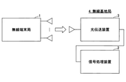
- FIG. 1 shows a configuration example of a wireless communication system according to the present embodiment.
- the wireless communication system in the present embodiment has a wireless terminal station 4 and a wireless base station 2.
- the radio terminal station 1 has a plurality of antennas
- the radio base station 4 has an optical transmission device 3 having one characteristic variable antenna and a signal processing device 2.
- the optical transmission device 3 and the signal processing device 2 are connected by an optical fiber.
- the number of characteristic variable antennas in the optical transmission device 3 may be plural.
- uplink communication from the wireless terminal station 1 to the wireless base station 4 is targeted.
- the signal processing device 2 may be referred to as a radio base station, and the optical transmission device 3 may be referred to as an overhanging base station.
- the radio base station 4 receives the signal transmitted from one radio terminal station 1, but this is an example.
- the technique according to the present embodiment can be applied even when the radio base station 4 receives signals transmitted from a plurality of radio terminal stations 1 (that is, in the case of multi-user MIMO). ..
- the radio base station 4 receives Massive MIMO with one characteristic variable antenna by the technique of Virtual Massive MIMO (VM-MIMO) disclosed in Non-Patent Document 1.
- VM-MIMO Virtual Massive MIMO
- the radio base station 4 receives signals transmitted from a plurality of antennas of the radio terminal station 1 at the same frequency and at the same time while periodically changing the antenna characteristics at high speed.
- the radio base station 4 samples the received signal at a higher speed than usual, divides and extracts the received signal at the timing when the antenna characteristics are the same from the sampled received signal, and extracts the extracted received signal in general.
- each extracted received signal can be regarded as a signal arriving from different propagation paths, so that the number of antennas can be virtually increased and Massive MIMO can be received.
- the radio base station 4 receives a signal while periodically changing the four antenna characteristics 1 to 4.
- the timing signal of the antenna characteristic 1 is indicated by “1”
- the timing signal of the antenna characteristic 2 is indicated by “2”
- the timing signal of the antenna characteristic 3 is indicated by "3”
- the antenna characteristic is indicated.
- the signal of the timing of 4 is indicated by "4".
- the antennas with antenna characteristics 1 to 4 are called virtual antennas 1 to 4, respectively.
- the waveform of the signal indicated by "1" is shown as the waveform of the virtual antenna 1.
- VM-MIMO By using the VM-MIMO technology, it is possible to demodulate MIMO signals transmitted from a plurality of antennas of the wireless terminal station 1 using one characteristic variable antenna of the wireless base station 4.
- the optical transmission device 3 and the optical fiber are included. Since the deviation between the timing of switching the antenna characteristics and the timing of sampling in the variable characteristic antenna becomes large, the reception processing of VM-MIMO cannot be performed normally, and the communication quality may be deteriorated.
- the processing capacity of the radio base station 4 that performs the reception processing of the VM-MIMO is limited, if the number of extracted signals to be the target of the MIMO demodulation processing is too large, the communication quality may deteriorate. Therefore, it is necessary to determine an appropriate number of extracted signals according to the propagation characteristics between transmission and reception including the variable characteristic antenna.
- the communication quality is improved by synchronizing the timing of switching the antenna characteristics of the variable characteristic antenna with the timing of sampling. Further, in the present embodiment, it is possible to adjust the number of extracted signals according to the propagation characteristics between transmission and reception including the characteristic variable antenna.
- the configuration and operation of each device will be described.
- FIG. 4 shows a configuration example of the wireless terminal station 1 according to the present embodiment.
- the radio terminal station 1 has a plurality of antennas 10, a plurality of RF units 11, a plurality of D / A conversion units 12, and a MIMO signal generation unit 13. It should be noted that the functional block generally mounted on the wireless terminal station 1 is omitted.
- the MIMO signal generation unit 13 generates a plurality of MIMO signals from the transmission data, and inputs each MIMO signal to the D / A conversion unit 12.
- the D / A conversion unit 12 converts the input digital MIMO signal into an analog signal, and outputs the analog signal to the RF unit 11.
- the RF unit 11 performs analog processing such as amplification, frequency conversion, and filtering on the analog signal, and outputs the processed signal to each antenna 10. It is assumed that the RF unit 11 here is equipped with the function of the RF front end of a general wireless device.
- the antenna 10 radiates the input signal into the air as a radio signal.
- FIG. 5 shows a configuration example of the radio base station 4 in the present embodiment.
- the radio base station 4 in the present embodiment has a characteristic variable antenna 20, a first RF unit 21, an A / D conversion unit 22, an antenna control unit 23, a signal extraction unit 24, and a MIMO signal demodulation unit 25. It has an index value calculation unit 26, an extraction signal number determination unit 27, an E / O conversion unit 28, an O / E conversion unit 29, an optical fiber 30, a second RF unit 31, and a synchronization unit 32.
- a device having an A / D conversion unit 22, a signal extraction unit 24, a MIMO signal demodulation unit 25, an index value calculation unit 26, an extraction signal number determination unit 27, an O / E conversion unit 29, and a second RF unit 31 is shown in FIG.
- the device corresponding to the signal processing device 2 shown in 2 and having the characteristic variable antenna 20, the first RF unit 21, the antenna control unit 23, the E / O conversion unit 28, and the synchronization unit 32 is the optical device shown in FIGS. 1 and 2.
- the antenna control unit 23 may be provided in the signal processing device 2 instead of being provided in the optical transmission device 3.
- the synchronization unit 32 may also be provided in the signal processing device 2 instead of being provided in the optical transmission device 3.
- the antenna control unit 23 and the synchronization unit 32 may be one functional unit, and the one functional unit may be referred to as a synchronization unit.
- the synchronization unit, which is one of the functional units, may be provided in the optical transmission device 3 or the signal processing device 2.
- the length of the optical fiber 30 is not particularly limited, but for example, a length of about 500 m to 20 km is assumed.
- the functions of each part are as follows.
- the characteristic variable antenna 20 is an antenna that periodically switches antenna characteristics (directivity, output power, phase, etc.) according to control information input from the antenna control unit 23.
- FIG. 6 shows a configuration example of the variable characteristic antenna 20.
- the characteristic variable antenna 20 shown in FIG. 6 is composed of a feeding element (Antenna element) arranged in the center and a plurality of non-feeding elements (Parasitic elements) arranged around the antenna control element 23, and is reflected by the antenna control unit 23. By changing the characteristics, the characteristics of the antenna can be changed.
- the signal received by the characteristic variable antenna 20 is output to the first RF unit 21.
- the first RF unit 21 performs processing such as amplification and filtering on the signal input from the characteristic variable antenna 20, and outputs the processed signal to the E / O conversion unit 28.
- the E / O conversion unit 28 converts the electric signal input from the first RF unit 21 into an optical signal, converts the optical signal into an optical signal of a method suitable for optical transmission, and outputs the optical signal to the optical fiber 30.
- the optical fiber 30 transmits the optical signal input from the E / O conversion unit 28 to the O / E conversion unit 29.
- the O / E conversion unit 29 converts the optical signal input from the optical fiber 30 into an electric signal, and outputs the converted electric signal to the second RF unit 31.
- the second RF unit 31 performs processing such as amplification, frequency conversion, and filtering on the input signal in order to convert the input signal into a signal that can be processed by the A / D conversion unit 22, and after the processing, the second RF unit 31 performs processing such as amplification, frequency conversion, and filtering.
- the signal is output to the A / D conversion unit 22.
- the A / D conversion unit 22 converts an analog signal input from the second RF unit 31 into a digital signal by sampling the analog signal, and outputs the digital signal to the signal extraction unit 24 and the index value calculation unit 26. Further, the A / D conversion unit 22 notifies the synchronization unit 32 of the sampling cycle and the sampling timing information.
- any medium may be used as the medium in which the A / D conversion unit 22 notifies the synchronization unit 32 of the sampling cycle and the timing information.
- the A / D conversion unit 22 and the synchronization unit 32 are connected by an electric cable, and the A / D conversion unit 22 transmits the sampling cycle and timing information to the synchronization unit 32 as an electric signal.
- the A / D conversion unit 22 and the synchronization unit 32 may be connected by an optical cable, and the A / D conversion unit 22 may transmit the sampling cycle and timing information to the synchronization unit 32 as an optical signal. Further, the A / D conversion unit 22 and the synchronization unit 32 may be wirelessly connected, and the A / D conversion unit 22 may transmit the sampling cycle and timing information to the synchronization unit 32 by a wireless signal.
- the synchronization unit 32 uses the sampling cycle and timing information input from the A / D conversion unit 22 and the antenna characteristic switching timing information input from the antenna control unit 23 to determine the sampling timing by the A / D conversion unit 22.
- the antenna characteristic switching cycle and timing information are adjusted (determined) so that the timing of the antenna characteristic switching by the characteristic variable antenna 20 is synchronized, and the adjusted antenna characteristic switching cycle and timing information are output to the antenna control unit 23.
- the timing of sampling by the A / D conversion unit 22 and the timing of antenna characteristic switching by the variable characteristic antenna 20 are taken into consideration in consideration of the delay of the transmission line such as the optical fiber 30. Synchronize.
- the antenna control unit 23 has an antenna control signal so that the antenna characteristics are switched in synchronization with the sampling timing by the A / D conversion unit 22 based on the antenna characteristic switching cycle and timing information input from the synchronization unit 32. Is output to the characteristic variable antenna 20.
- the signal extraction unit 24 divides the signal input from the A / D conversion unit 22 in synchronization with the sampling cycle, and a plurality of divided signals obtained based on the information input from the extraction signal number determination unit 27. From the signals, the signal to be output to the MIMO signal demodulator 25 is extracted (selected), and the extracted signal is output to the MIMO signal demodulator 25.
- the MIMO signal demodulation unit 25 performs the MIMO demodulation processing defined in a general wireless communication system with respect to the signal received from the signal extraction unit 24.
- the index value calculation unit 26 uses each antenna from the signal input from the A / D conversion unit 22 based on the control information of the antenna input from the antenna control unit 23.
- the propagation channel response in the characteristic is calculated, and the correlation value of the propagation channel response between the antenna characteristics set by the characteristic variable antenna 20 is calculated.
- the correlation value is a numerical representation of the difference between different antenna characteristics.
- the calculated channel correlation value is output to the extraction signal number determination unit 27.
- the extraction signal number determination unit 27 calculates the number of extraction signals based on the index value input from the index value calculation unit 26 and outputs it to the signal extraction unit 24. An example of a method for calculating the number of extracted signals will be described later.
- the A / D conversion unit 22 is a general radio base. Signals 1 to 4 corresponding to each antenna characteristic are sampled and output at a sampling period that is four times or more the sampling period of the A / D conversion unit 22 of the station.
- the antenna control unit 23 selects one of the four virtual antennas in the sampling cycle of the A / D conversion unit 22 and switches the antenna characteristics.
- the signal extraction unit 24 divides and extracts the signals 1 to 4 corresponding to each antenna characteristic in the same sampling period as the sampling period of the A / D conversion unit 22, and outputs the signals to the MIMO signal demodulation unit 25.
- signals 1 to 4 having the same antenna characteristics are periodically output to the four output ports of the signal extraction unit 24.
- each functional block in the signal processing device 2 shown in FIG. 5 may be realized by dedicated hardware (LSI or the like), or "O / E conversion unit 29, second RF unit 31, A / D conversion unit 22" may be realized.
- a part other than "(that is, a part that processes a digital signal) may be realized by a general-purpose computer including a processor (CPU, DSP, etc.) and a memory, and software running on the computer.
- FIG. 7 shows a configuration example of the signal processing device 2 when the signal processing device 2 is realized by using a computer and software.
- the signal processing device 2 includes a processor 101, a memory 102, an auxiliary storage device 103, an input / output device 104, an O / E conversion unit 29, a second RF unit 31, and an A / D conversion unit 22. However, they have a configuration in which they are connected by a bus.
- the auxiliary storage device 103 stores a program that realizes the operation of the signal processing device 2.
- the program is read into the memory 102, and the processor 101 reads the program from the memory 102 and executes it.
- the processor 101 executes the processing of the signal extraction unit 24, the MIMO signal demodulation unit 25, the index value calculation unit 26, and the extraction signal number determination unit 27 by the program.
- the synchronization unit 32 is included in the signal processing device 2, the processing of the signal extraction unit 24, the MIMO signal demodulation unit 25, the index value calculation unit 26, the extraction signal number determination unit 27, and the synchronization unit 32 by the program. To execute.
- the signal extraction unit 24 When the synchronization unit 32 and the antenna control unit 23 are included in the signal processing device 2, the signal extraction unit 24, the MIMO signal demodulation unit 25, the index value calculation unit 26, the extraction signal number determination unit 27, and so on, according to the program.
- the processing of the synchronization unit 32 and the antenna control unit 23 is executed.
- the input / output device 104 outputs, for example, the signal obtained by the MIMO signal demodulation unit 25. Further, the information set in advance may be input from the input / output device 104.
- the characteristic variable antenna 20 follows the antenna control signal received from the antenna control unit 23, for example, virtual antenna 1-> virtual antenna 2-> virtual antenna 3-> virtual antenna 4-> virtual antenna 1-> ....
- the antenna characteristics are switched as in.
- the characteristic variable antenna 20 switches the antenna characteristic from the virtual antenna 4 to the virtual antenna 1 at time T1 based on the antenna control signal received from the antenna control unit 23, and at time T2. It is assumed that the antenna characteristic is switched from the virtual antenna 1 to the virtual antenna 2.
- the characteristic variable antenna 20 receives the signal by the virtual antenna 1 in the time from T1 to T2 (time from T1 to T2), and outputs the analog signal in the time from T1 to T2 as the received signal by the virtual antenna 1. do.
- This analog signal reaches the A / D conversion unit 22 via the first RF unit 21, the E / O conversion unit 28, the optical fiber 30, the O / E conversion unit 29, and the second RF unit 31.
- the analog signal obtained by the virtual antenna 1 in the time T1 to T2 in the virtual antenna 1 is delayed by the time D, and reaches T3 to T4 in the A / D conversion unit 22. ..
- the A / D conversion unit 22 in order for the A / D conversion unit 22 to sample the received signal by the virtual antenna 1, the time when the characteristic variable antenna 20 actually receives the signal by the virtual antenna 1 (eg, the center of T1 and T2). It is necessary to perform sampling at the time after the time D from the time).
- the A / D conversion unit 22 inputs the sampling period and the timing information to the synchronization unit 32, and the antenna control unit 23 inputs the antenna characteristic switching timing information. Is input to the synchronization unit 32.
- the timing information input from the A / D conversion unit 22 is, for example, the time when the received signal of the virtual antenna 1 shown in FIG. 8 is sampled (for example, the time at the center of T3 and T4 (T3 + T4) / 2)). be.
- the antenna characteristic switching timing information input from the antenna control unit 23 is, for example, the switching time shown in FIG. 8 (example: either or both of T1 and T2) and the antenna characteristic information at that time (FIG. 8). Then, it is a virtual antenna 1).
- the synchronization unit 32 appropriately desires the A / D conversion unit 22 based on the sampling cycle and timing information input from the A / D conversion unit 22 and the antenna characteristic switching timing information input from the antenna control unit 23.
- the antenna characteristic switching cycle) and timing information are adjusted so that the signal is sampled, and the adjusted antenna characteristic switching cycle and timing information are output to the antenna control unit 23.
- the antenna control unit 23 outputs an antenna control signal to the characteristic variable antenna 20 based on the adjusted antenna characteristic switching cycle and timing information.
- D may be set in advance in the synchronization unit 32, for example, the A / D conversion unit 22 (or the O / E conversion unit 29, etc.) periodically measures D and notifies the synchronization unit 32 of D. You may.
- the synchronization unit 32 receives SP as a sampling cycle and ST as timing information from the A / D conversion unit 22, and receives antenna characteristic switching timing information from the antenna control unit 23 by the virtual antenna 1 at T1 to T2.
- SP as a sampling cycle
- ST as timing information from the A / D conversion unit 22
- antenna characteristic switching timing information from the antenna control unit 23 by the virtual antenna 1 at T1 to T2.
- the synchronization unit 32 compares the sampling cycle SP with the antenna characteristic switching cycle “T2-T1”, and if the SP is different from the current antenna switching cycle “T2-T1”, T2-
- the antenna switching cycle to be output to the subsequent antenna control unit 23 is adjusted so that T1 matches the SP.
- the antenna control unit 23 controls the variable characteristic antenna 20 so that the antenna characteristics are switched at that cycle.
- the unit 32 compares the delay time D with (ST- (T2 + T1) / 2). If D> (ST- (T2 + T1) / 2), it means that the switching of the antenna characteristics is too late, so the timing information to be output to the subsequent antenna control unit 23 so as to advance the switching timing of the antenna characteristics. To adjust.
- the antenna control unit 23 that has received the adjusted timing information switches the antenna characteristics at a time according to the adjusted timing information (example: T1 and T2 in FIG. 8).
- the A / D conversion unit 22 wants to sample the signal at the center time of the period of reception by the virtual antenna 1 as the signal of the virtual antenna 1, the above adjustment is performed. As a result, the signal is received by the virtual antenna 1 at an appropriate time (a time before the sampling time by the delay time D). Since the virtual antenna switches periodically, if one virtual antenna can sample the signal correctly, the other virtual antenna can also sample the signal correctly.
- the antenna characteristic switching cycle and timing may be updated by the synchronization unit 32 at all times (every time the antenna is switched) or at predetermined time intervals.
- the antenna control unit 23 outputs an antenna control signal synchronized with the antenna characteristic switching cycle and timing information received from the synchronization unit 32 to the characteristic variable antenna 20, and the characteristic variable antenna 20 determines the antenna characteristics according to the antenna control signal. It is switching periodically.
- the characteristic variable antenna 20 receives signals transmitted simultaneously from a plurality of antennas of the wireless terminal station 1.
- the received signal is input to the first RF unit 21, input from the first RF unit 21 to the E / O conversion unit 28, the electric signal is converted into an optical signal by the E / O conversion unit 28, and the converted optical signal is optical. It is transmitted by the fiber 30 and input to the O / E conversion unit 29.
- the O / E conversion unit 29 converts an optical signal into an electric signal and outputs it to the second RF unit 31.
- the signal processed by the second RF unit 31 is output to the A / D conversion unit 22.
- the A / D conversion unit 22 performs sampling on the input signal (analog signal) and acquires the sampled signal (digital signal).
- the signal obtained by the A / D conversion unit 22 is output to the signal extraction unit 24 and the index value calculation unit 26.
- the timing of the change in the antenna characteristics and the timing of sampling are synchronized by the adjustment by the synchronization unit 32.
- the index value calculation unit 26 calculates the propagation channel response in each antenna characteristic from the signal input from the A / D conversion unit 22 based on the control information of the antenna input from the antenna control unit 23. , The correlation value (channel correlation value) of the propagation channel response between the antenna characteristics set by the characteristic variable antenna 20 is calculated.
- the index value calculation unit 26 calculates the correlation value of the propagation channel response between the antenna characteristics, for example, by the following equation 1.
- Equation 1 ai is the propagation channel response vector between the antenna at a certain antenna characteristic and the i -th antenna of the radio terminal station 1, and bi is the antenna and the radio terminal station 1 at an antenna characteristic different from ai . It is a propagation channel response vector to and from the i-th antenna of.
- the index value calculation unit 26 calculates the channel correlation value in all the antenna characteristics by obtaining the channel correlation value by the equation 1 for each set of antenna characteristics and adding the channel correlation values of all the sets.
- the antennas in each characteristic are referred to as a virtual antenna 1, a virtual antenna 2, a virtual antenna 3, and a virtual antenna 4.
- the index value calculation unit 26 uses the channel correlation value between the virtual antenna 1 and the virtual antenna 2, the channel correlation value between the virtual antenna 1 and the virtual antenna 3, and the interval between the virtual antenna 1 and the virtual antenna 4.
- the virtual antennas 1, 2 and 3 are used.
- the channel correlation value, the channel correlation value between the virtual antennas 1, 2 and 4, and the channel correlation value between the virtual antennas 2, 3 and 4 may be calculated. That is, the channel correlation value may be calculated for all combinations.
- the extraction signal number determination unit 27 calculates the number of extraction signals based on the channel correlation value input from the index value calculation unit 26, and outputs the calculation result to the signal extraction unit 24.
- the extraction signal number determination unit 27 holds a table showing the relationship between the channel correlation value calculated in advance by simulation or actual measurement and the transmission capacity, and is based on the channel correlation value calculated by the index value calculation unit 26. Refer to the table to determine the minimum number of extracted signals that will reduce the amount of transmission capacity degradation below the threshold.
- the threshold value is a value given in advance.
- the larger the number of extracted signals (that is, the larger the number of virtual antennas used to receive the signal input to the MIMO signal demodulation unit 25), the larger the transmission capacity, but if the number of extracted signals becomes too large, MIMO The processing load of the signal demodulation unit 25 becomes excessive.
- the degree of increase in transmission capacity with respect to the increase in the number of extracted signals decreases as the number of extracted signals increases. For example, the amount of increase in transmission capacity when the number of extracted signals increases from 16 to 18 is smaller than the amount of increase in transmission capacity when the number of extracted signals increases from 10 to 12.
- the transmission capacity in the number of extracted signals M smaller than N is deteriorated as compared with the transmission capacity when the number of extracted signals equal to the number of virtual antennas used for switching (referred to as N for convenience) is used.
- the "minimum number of extracted signals whose transmission capacity deterioration amount is equal to or less than the threshold value" is set so that the processing load of the MIMO signal demodulation unit 25 does not become excessive while reducing the deterioration of the transmission capacity. It is decided and notified to the signal extraction unit 24.
- the extraction signal number determination unit 27 holds a table as shown in FIG. 10 for each number of virtual antennas used for signal reception while switching.
- the extraction signal number determination unit 27 refers to the table of FIG. 9 held by itself to obtain the number of extraction signals. , "N1" is determined.
- the extraction signal number determination unit 27 may determine only the number of extraction signals as described above, or in addition to the number of extraction signals, the number of virtual antennas (which virtual antenna signal is used). ) May be determined.
- the extraction signal number determination unit 27 is, for example, a set of virtual antennas having the minimum channel correlation value (weak correlation) between the number of virtual antennas. Is selected (determined).
- the extraction signal number determination unit 27 determines virtual antennas 1, 2 and 3 as virtual antennas for the determined number of extraction signals.
- the extraction signal number determination unit 27 notifies the signal extraction unit 24 of the number of extraction signals determined in S4.
- the extraction signal number determination unit 27 notifies the signal extraction unit 24 of the virtual antenna for the number of extraction signals determined in S4 in S5. do.
- the signal extraction unit 24 has the same sampling period as the sampling period of the A / D conversion unit 22 for the signal input from the A / D conversion unit 22 based on the number of extraction signals received from the extraction signal number determination unit 27.
- the signal of the number of extracted signals is extracted (selected) from the divided signals, and the extracted signal is output to the MIMO signal demodulator 25.
- the maximum number of signals that can be extracted by the signal extraction unit 24 may be predetermined. In that case, when the signal extraction unit 24 is notified of the number of extraction signals larger than the maximum number of signals, the signal extraction unit 24 extracts the signal with the maximum number of signals and uses the extracted signal as a MIMO signal. Output to the demodulation unit 25.
- the signal extraction unit 24 receives only the number of extraction signals from the extraction signal number determination unit 27, which signal is extracted from the divided signals is not limited to a specific method, but for example, which signal is extracted. It may be decided in advance.
- the signal extraction unit 24 extracts the signals of the virtual antennas 1, 2 and 3 from the signals of the virtual antennas 1 to 4 and outputs them to the MIMO signal demodulation unit 25. do.
- the signal extraction unit 24 uses the extraction signal number determination unit 27 from the divided signals.
- the notified signal is extracted and output to the MIMO signal demodulator 25.
- FIG. 11 shows an image of the operation by the signal extraction unit 24.
- virtual antennas 1 to 8 are used.
- the signals corresponding to the virtual antennas 1 to 8 are the signals 1 to 8 (in the figure, the circles with numbers indicate the signals).
- the signal extraction unit 24 receives the signal sampled by the A / D conversion unit 22.
- the signal extraction unit 24 divides the input signal in the same cycle as the sampling cycle, so that the signals 1, 2, 3, 4, 5, 6, 7, 8, ... Are sequentially acquired (identified).
- the extraction signal number determination unit 27 specifies to the signal extraction unit 24 to extract signals 1, 4, 7, and 8 from the signals 1 to 8.
- the signal extraction unit 24 extracts signals 1, 4, 7, and 8 from the signals 1 to 8, and outputs these signals to the MIMO signal demodulation unit 25.
- the MIMO signal demodulation unit 25 performs the MIMO demodulation processing defined in a general wireless communication system with respect to the signal received from the signal extraction unit 24.
- Information required for MIMO demodulation processing may be given in advance or may be estimated.
- the channel correlation value between virtual antennas is used as an index value for determining the number of extracted signals, but this is an example.
- the number of extracted signals may be determined using an index value other than the channel correlation value.
- the index value calculation unit 26 calculates the theoretical transmission capacity C based on the virtual antenna used by the following equation 2 instead of the channel index value.
- Pt is the transmission power.
- ⁇ 2 n is noise power.
- H is a Nr ⁇ Nt channel matrix (a matrix having a propagation channel response as an element), and det is a determinant of the matrix in parentheses.
- the characteristic variable antenna 20 switches between four antenna characteristics. That is, it is assumed that the virtual antenna 1, the virtual antenna 2, the virtual antenna 3, and the virtual antenna 4 are used.
- the index value calculation unit 26 calculates the transmission capacity when the virtual antennas 1 to 4 are used by using the equation 2.
- the transmission capacity when the virtual antennas 2, 3 and 4 are used may be calculated. That is, the transmission capacity may be calculated for all combinations.
- the extraction signal number determination unit 27 calculates the number of extraction signals from the transmission capacity input from the index value calculation unit 26, and outputs the calculation result to the signal extraction unit 24.
- the extraction signal number determination unit 27 holds a table in which the transmission capacity is associated with the “minimum number of extraction signals at which the deterioration of the transmission capacity is equal to or less than the threshold value” for each number of virtual antennas to be used. There is.
- the extraction signal number determination unit 27 determines "N1" as the extraction signal number by referring to the table.
- the extraction signal number determination unit 27 may determine only the number of extraction signals as described above, or in addition to the number of extraction signals, the number of virtual antennas (which virtual antenna signal is used). ) May be determined.
- the extraction signal number determination unit 27 selects (determines), for example, the set of virtual antennas that maximizes the transmission capacity of the number of virtual antennas. ..
- the extraction signal number determination unit 27 determines the virtual antennas 1, 2, and 3 as the virtual antennas of the determined extraction signal numbers.
- an eigenvalue or a received power to noise power ratio may be used.
- the eigenvalue is an eigenvalue obtained by decomposing the channel matrix H into eigenvalues, and is a value corresponding to the received power for each spatial transmission.
- the received power to noise power ratio (SNR) is a value obtained by dividing the above eigenvalues by the noise power.
- Modification example The basic configuration has been described above as a basic example, but in order to further improve the characteristics, the configuration and operation as described in the following modification examples 1 to 6 may be adopted. A part or all of the modifications 1 to 5 may be combined. Further, the basic example is applied to the parts not explained in the modified examples 1 to 5.
- the A / D conversion unit 22 oversamples to perform sampling more finely than the sampling in the above-mentioned basic example, and the synthesis of those signals results in less than the sampling period. Generate a periodic signal.
- the signal synthesis is performed by the signal extraction unit 24.
- the processing after signal synthesis is the same as the processing of the basic example.
- FIG. 12 shows an image of signal processing in the first modification.
- the virtual antenna is switched as 1, 2, 3, 4, ... In a predetermined cycle, and an analog signal is obtained by the corresponding virtual antenna at the time of each cycle. ing.
- the A / D conversion unit 22 performs sampling at twice the speed of switching the virtual antennas, as shown in FIG. 12, two virtual antennas are used within the time when one virtual antenna is used.
- the digital signal is sampled.
- the signal extraction unit 24 generates a signal obtained by synthesizing the signal A and the signal B as the signal of the virtual antenna 1. The same applies to other virtual antennas.
- the characteristic variable antenna 20 periodically switches the characteristics so that the same characteristics are continuously performed by a predetermined number based on the control information from the antenna control unit 23.
- the predetermined number 2
- the A / D conversion unit 22 outputs a signal sequence in which adjacent signals are periodically the same, such as signal 1, signal 1, signal 2, signal 2, ..., By sampling. do.
- FIG. 13 shows an image of the processing in the signal extraction unit 24 in this case.
- the signals 1 to 4 are extracted from the signals 1 to 8.
- the signal extraction unit 24 synthesizes adjacent signals and outputs the combined signal to the MIMO signal demodulation unit 25. This function can be expected to improve the signal-to-noise power ratio.
- ⁇ Modification 3> In the third modification, different antenna control patterns (sets of virtual antennas) are set for the antenna control unit 23 in FIG. 5, and the index value (eg, channel correlation) is set in the index value calculation unit 26 for each antenna control pattern. , Transmission capacity) is calculated.
- the index value eg, channel correlation
- the index value calculation unit 26 calculates the index value
- the same calculation method as the above-mentioned basic example may be used, or the deterioration amount peculiar to the optical fiber such as wavelength dispersion is set as noise and the index value is calculated. You may.
- the noise is set to calculate the propagation channel response, and the propagation channel response is used to calculate the index value (eg, channel correlation). , Transmission capacity) is calculated.
- the amount of deterioration peculiar to the optical fiber may be notified from the O / E conversion unit 29 to the index value calculation unit 26, or may be preset in the index value calculation unit 26.
- the antenna control pattern that minimizes the channel correlation value among the plurality of antenna control patterns is set in the antenna control unit 23.
- the antenna control pattern that maximizes the transmission capacity among the plurality of antenna control patterns is set in the antenna control unit 23.
- the determination of the antenna control pattern and the setting to the antenna control unit 23 may be performed by the index value calculation unit 26 or by a device outside the radio base station 2. Further, the setting to the antenna control unit 23 may be performed wirelessly or by wire (electrical or optical).
- the modification 3 makes it possible to improve the transmission capacity.
- the antenna characteristics of the variable antenna 20 that can be realized by the control from the antenna control unit 23 include antenna characteristics 1 to 10 (virtual antennas 1 to 10).
- the signal reception is performed by switching the characteristics of the five antennas. That is, it is assumed that signals are received using 5 virtual antennas out of 10 feasible virtual antennas.
- the antenna control pattern A ⁇ 1, 2, 3, 4, 5 ⁇
- the antenna control pattern B ⁇ 6, 7, 8, 9, 10 ⁇
- antenna control pattern C ⁇ 2, 3, 4, 5, 6 ⁇
- antenna control pattern D ⁇ 4, 5, 6, 10 ⁇ , ....
- the antenna control unit 23 causes the characteristic variable antenna 20 to receive signals while switching the antenna characteristics in each antenna control pattern. For example, when the antenna control pattern A is applied, the antenna characteristics are switched such as 1, 2, 3, 4, and 5. Then, the index value calculation unit 26 calculates the index value in each antenna control pattern, and determines one antenna control pattern based on the index value.
- the upper limit of the extraction signal number is limited to the number that can be calculated by the MIMO signal demodulation unit 25. As a result, the calculation load can be suppressed.
- ⁇ Modification 5> When the signal received by the characteristic variable antenna 20 is transmitted as an optical signal by the optical fiber 30 as in the present embodiment, the transmission distance is extended and the signal is deteriorated due to a non-linear effect such as wavelength dispersion in the optical fiber 30. do.
- the extraction signal number determination unit 27 determines the number of extraction signals larger than the number of extraction signals calculated from the index values (channel correlation value, transmission capacity, etc.) based on the propagation channel response and the like.
- the extraction signal number determination unit 27 holds a table in which the number of extraction signals obtained from the index value and the number of signals to be added are associated with each other. This table is prepared in advance by the length of the optical fiber 30 or a simulation in advance. For example, when the number of extracted signals obtained from the index value is 10, and if 2 is obtained as the value corresponding to 10 from the table, the extraction signal number determination unit 27 sets 12 as the final number of extracted signals. decide.
- an optical transmission device including a characteristic variable antenna that receives MIMO signals transmitted from a plurality of antennas of the transmission device at the same frequency and at the same time, and a signal processing device are connected by an optical fiber.
- the timing of switching the antenna characteristics of the variable antenna and the timing of sampling can be synchronized.
- This specification describes at least the receiving device, the signal processing device, the receiving method, and the program described in each of the following sections.
- (Section 1) A variable antenna with characteristics that receives MIMO signals transmitted from multiple antennas while switching the antenna characteristics, An electro-optical conversion unit that converts the received signal received by the variable characteristic antenna from an electric signal to an optical signal, and An optical-electric conversion unit that receives the optical signal transmitted by an optical fiber and converts the optical signal into an electric signal.
- a conversion unit that performs sampling on the received signal converted into an electric signal by the optical-electric conversion unit, and a conversion unit.
- a signal extraction unit that extracts signals from a plurality of signals corresponding to a plurality of antenna characteristics obtained by the conversion unit, and a signal extraction unit.
- a MIMO signal demodulation unit that executes MIMO demodulation processing on the signal output from the signal extraction unit, and A synchronization unit that adjusts the cycle and timing of switching the antenna characteristics in the variable antenna based on the sampling cycle, the sampling timing information, and the timing information for switching the antenna characteristics in the variable antenna.
- a receiver equipped with. The synchronization unit has a delay between the time when the signal is received with a certain antenna characteristic and the time of the sampling based on the information of the timing of the sampling and the information of the timing of switching the antenna characteristic in the variable antenna. The time is calculated, and the timing of switching the antenna characteristics is adjusted by comparing the calculated delay time with the delay time until the received signal received by the characteristic variable antenna reaches the conversion unit.
- the receiving device according to item 1.
- An index value calculation unit that calculates an index value based on the signal obtained by the conversion unit, and an index value calculation unit.
- a unit for determining the number of extracted signals which determines the number of extracted signals based on the index value, is provided.
- the receiving device according to item 1 or 2, wherein the signal extraction unit extracts a signal having the number of extracted signals from a plurality of signals corresponding to a plurality of antenna characteristics obtained by the conversion unit.
- the signal extraction unit extracts a signal having the number of extracted signals from a plurality of signals corresponding to a plurality of antenna characteristics obtained by the conversion unit.
- the synchronization unit receives the sampling cycle and the sampling timing information from the conversion unit, and receives the timing information for switching the antenna characteristics from the antenna control unit.
- Optical transmission including a characteristic variable antenna that receives MIMO signals transmitted from a plurality of antennas while switching antenna characteristics, and an electric optical conversion unit that converts the received signal received by the characteristic variable antenna from an electric signal to an optical signal.
- An optical-electric conversion unit that receives the optical signal transmitted by an optical fiber from the device and converts the optical signal into an electric signal.
- a conversion unit that performs sampling on the received signal converted into an electric signal by the optical-electric conversion unit, and a conversion unit.
- a signal extraction unit that extracts signals from a plurality of signals corresponding to a plurality of antenna characteristics obtained by the conversion unit, and a signal extraction unit.
- a MIMO signal demodulation unit that executes MIMO demodulation processing on the signal output from the signal extraction unit, and A synchronization unit that adjusts the cycle and timing of switching the antenna characteristics in the variable antenna based on the sampling cycle, the sampling timing information, and the timing information for switching the antenna characteristics in the variable antenna.
- a signal processing device (Section 6)
- the synchronization unit is a delay between the time when a signal is received with a certain antenna characteristic and the time of the sampling based on the information of the timing of the sampling and the information of the timing of switching the antenna characteristic in the variable antenna. The time is calculated, and the timing of switching the antenna characteristics is adjusted by comparing the calculated delay time with the delay time until the received signal received by the characteristic variable antenna reaches the conversion unit.
- the signal processing apparatus It is a receiving method executed by a receiving device equipped with a variable characteristic antenna.
- the step of executing MIMO demodulation processing on the extracted signal and Based on the sampling cycle, the sampling timing information, and the timing information for switching the antenna characteristics in the characteristic variable antenna, the step of adjusting the switching cycle and timing of the antenna characteristics in the characteristic variable antenna is performed.
- (Section 8) A program for causing a computer to function as the signal extraction unit, the MIMO signal demodulation unit, and the synchronization unit in the
- Radio terminal station 4 Radio base station 10 Antenna 11 RF unit 12 D / A conversion unit 13 MIMO signal generation unit 20 Characteristic variable antenna 21 RF unit 22 A / D conversion unit 23 Antenna control unit 24 Signal extraction unit 25 MIMO signal demodulation unit 26 Index value calculation unit 27 Extracted signal number determination unit 28 E / O conversion unit 29 O / E conversion unit 30 Optical fiber 31 Second RF unit 32 Synchronization unit 101 Processor 102 Memory 103 Auxiliary storage device 104 Input / output device
Landscapes
- Engineering & Computer Science (AREA)
- Computer Networks & Wireless Communication (AREA)
- Signal Processing (AREA)
- Radio Transmission System (AREA)
- Mobile Radio Communication Systems (AREA)
Abstract
受信装置において、複数のアンテナから送信されたMIMO信号を、アンテナ特性を切り替えながら受信する特性可変アンテナと、前記受信した受信信号を電気信号から光信号に変換する電気光変換部と、光ファイバにより伝送された前記光信号を受信し、当該光信号を電気信号に変換する光電気変換部と、前記光電気変換部により電気信号に変換された前記受信信号に対してサンプリングを行う変換部と、前記変換部により得られた複数のアンテナ特性に対応する複数の信号から、信号を抽出する信号抽出部と、前記信号抽出部から出力された信号に対してMIMO復調処理を実行するMIMO信号復調部と、前記サンプリングの周期と、前記サンプリングのタイミングの情報と、前記特性可変アンテナにおいてアンテナ特性を切り替えるタイミングの情報とに基づいて、前記特性可変アンテナにおけるアンテナ特性の切り替えの周期とタイミングを調整する同期部と、を備える。
Description
本発明は、MIMO(Multiple Input Multiple Output)通信を行う無線通信システムに関連するものである。
無線デバイスの急速な普及によって無線通信トラヒックが増加し続けている。この無線通信トラヒックを安定的に収容するために、無線通信システムの大容量化が求められている。無線通信システムの大容量化を実現するべく、複数のアンテナを用いて同一周波数かつ同一時刻に空間分割多重伝送を行うMIMOが実用化されている。更に、将来無線通信システムを対象として、MIMOが実現する容量の更なる拡大に向けて、超多数のアンテナを利用した大規模(Massive)MIMOの研究開発が進められている。
しかしながら、Massive MIMOでは、無線基地局に超多数のアンテナ、各アンテナに接続される増幅やフィルタ等を行うRF部、及びアナログ信号とデジタル信号の変換を行う変換部等の装置が非常に多く必要となることから、無線基地局のサイズ及びコストが大きくなるという課題がある。
上記課題に対して、非特許文献1には、Virtual Massive MIMO(VM-MIMO)の技術が開示されている。非特許文献1に開示されたVirtual Massive MIMO(VM-MIMO)では、上り回線のMassive MIMOにおいて、複数のアンテナから同一周波数かつ同一時刻に送信される信号に対して、無線基地局が特性可変アンテナにより周期的にアンテナ特性を高速に切り替えながら受信を行う。更に、通常よりも高速にサンプリングした受信信号からアンテナ特性が同等となるタイミングの信号を、サンプリングした受信信号から分割して抽出し、抽出した信号に対して、一般的なマルチユーザMIMOの受信処理を行うことで、少ないアンテナでMassive MIMOの受信を可能としている。
村上他、"将来無線システムにおける時空間信号処理技術"電子情報通信学会 ソサイエティ大会2019
上記のように、VM-MIMOの技術により、少ないアンテナでMassive MIMOの受信を実現できるので、無線基地局のサイズ及びコストを低減できる。
また、更なる経済化に向けて、無線基地局において、信号処理を行う信号処理装置と、特性可変アンテナを備える光伝送装置とが光ファイバで接続される構成が採用されることが考えられる。しかしながら、光伝送装置と光ファイバが含まれることで、特性可変アンテナにおけるアンテナ特性の切り替えのタイミングとサンプリングのタイミングとの間のずれが大きくなることから、VM-MIMOの受信処理が正常にできなくなり、通信品質の劣化が生じる可能性がある。
なお、上記のような課題は、VM-MIMOの受信処理を行う無線基地局のみならず、VM-MIMOの受信処理を行う他の受信装置においても生じ得る課題である。
本発明は上記の点に鑑みてなされたものであり、送信装置の複数のアンテナから同一周波数かつ同一時刻に送信されるMIMO信号を受信する特性可変アンテナを備える光伝送装置と、信号処理装置とが光ファイバで接続される受信装置において、特性可変アンテナのアンテナ特性の切り替えのタイミングとサンプリングのタイミングとを同期させるための技術を提供することを目的とする。
開示の技術によれば、複数のアンテナから送信されたMIMO信号を、アンテナ特性を切り替えながら受信する特性可変アンテナと、
前記特性可変アンテナにより受信した受信信号を電気信号から光信号に変換する電気光変換部と、
光ファイバにより伝送された前記光信号を受信し、当該光信号を電気信号に変換する光電気変換部と、
前記光電気変換部により電気信号に変換された前記受信信号に対してサンプリングを行う変換部と、
前記変換部により得られた複数のアンテナ特性に対応する複数の信号から、信号を抽出する信号抽出部と、
前記信号抽出部から出力された信号に対してMIMO復調処理を実行するMIMO信号復調部と、
前記サンプリングの周期と、前記サンプリングのタイミングの情報と、前記特性可変アンテナにおいてアンテナ特性を切り替えるタイミングの情報とに基づいて、前記特性可変アンテナにおけるアンテナ特性の切り替えの周期とタイミングを調整する同期部と、
を備える受信装置が提供される。
前記特性可変アンテナにより受信した受信信号を電気信号から光信号に変換する電気光変換部と、
光ファイバにより伝送された前記光信号を受信し、当該光信号を電気信号に変換する光電気変換部と、
前記光電気変換部により電気信号に変換された前記受信信号に対してサンプリングを行う変換部と、
前記変換部により得られた複数のアンテナ特性に対応する複数の信号から、信号を抽出する信号抽出部と、
前記信号抽出部から出力された信号に対してMIMO復調処理を実行するMIMO信号復調部と、
前記サンプリングの周期と、前記サンプリングのタイミングの情報と、前記特性可変アンテナにおいてアンテナ特性を切り替えるタイミングの情報とに基づいて、前記特性可変アンテナにおけるアンテナ特性の切り替えの周期とタイミングを調整する同期部と、
を備える受信装置が提供される。
開示の技術によれば、送信装置の複数のアンテナから同一周波数かつ同一時刻に送信されるMIMO信号を受信する特性可変アンテナを備える光伝送装置と、信号処理装置とが光ファイバで接続される受信装置において、特性可変アンテナのアンテナ特性の切り替えのタイミングとサンプリングのタイミングとを同期させるための技術が提供される。
以下、図面を参照して本発明の実施の形態(本実施の形態)を説明する。以下で説明する実施の形態は一例に過ぎず、本発明が適用される実施の形態は、以下の実施の形態に限られるわけではない。
なお、以下の説明では、送信装置として無線端末局1を使用し、受信装置として無線基地局4を使用する例を用いているが、送信装置として無線端末局1以外の装置を使用し、受信装置として無線基地局4以外の装置を使用する場合にも、本発明に係る技術を適用することが可能である。
(全体構成)
図1に、本実施の形態における無線通信システムの構成例を示す。図1に示すように、本実施の形態における無線通信システムは、無線端末局4と無線基地局2とを有する。無線端末局1は複数のアンテナを有しており、無線基地局4は、1本の特性可変アンテナを有する光伝送装置3と、信号処理装置2とを有する。光伝送装置3と信号処理装置2との間は光ファイバで接続されている。光伝送装置3における特性可変アンテナの数は複数であってもよい。図示のとおり、本実施の形態では、無線端末局1から無線基地局4への上り方向の通信を対象としている。なお、信号処理装置2を無線基地局と呼び、光伝送装置3を張出し基地局と呼んでもよい。
図1に、本実施の形態における無線通信システムの構成例を示す。図1に示すように、本実施の形態における無線通信システムは、無線端末局4と無線基地局2とを有する。無線端末局1は複数のアンテナを有しており、無線基地局4は、1本の特性可変アンテナを有する光伝送装置3と、信号処理装置2とを有する。光伝送装置3と信号処理装置2との間は光ファイバで接続されている。光伝送装置3における特性可変アンテナの数は複数であってもよい。図示のとおり、本実施の形態では、無線端末局1から無線基地局4への上り方向の通信を対象としている。なお、信号処理装置2を無線基地局と呼び、光伝送装置3を張出し基地局と呼んでもよい。
本実施の形態では、図1に示すように、無線基地局4が、1台の無線端末局1から送信された信号を受信することを想定しているが、これは一例である。図2に示すように、無線基地局4が複数の無線端末局1から送信された信号を受信する場合(つまり、マルチユーザMIMOの場合)にも本実施の形態に係る技術を適用可能である。
(無線通信システムの動作概要)
無線基地局4は、非特許文献1に開示されたVirtual Massive MIMO(VM-MIMO)の技術により、1本の特性可変アンテナでMassive MIMOの受信を行う。
無線基地局4は、非特許文献1に開示されたVirtual Massive MIMO(VM-MIMO)の技術により、1本の特性可変アンテナでMassive MIMOの受信を行う。
すなわち、図3に示すように、無線基地局4は、無線端末局1の複数のアンテナから同一周波数かつ同一時刻に送信される信号を、周期的にアンテナ特性を高速に変化させながら受信する。無線基地局4は、通常よりも高速に受信信号をサンプリングして、サンプリングした受信信号からアンテナ特性が同等となるタイミングの受信信号を分割して抽出し、抽出した受信信号に対して、一般的なMIMOの受信処理を行うことで、1本の特性可変アンテナでMassive MIMOの受信を可能としている。
すなわち、理論的には、抽出した各受信信号は、互いに異なる伝搬路から到来する信号とみなすことができるので、仮想的にアンテナを増加させることができ、Massive MIMOの受信が可能となる。
図3の例では、無線基地局4は、4つのアンテナ特性1~4を周期的に変化させながら信号を受信している。図3の例において、アンテナ特性1のタイミングの信号を"1"ので示し、アンテナ特性2のタイミングの信号を"2"で示し、アンテナ特性3のタイミングの信号を"3"で示し、アンテナ特性4のタイミングの信号を"4"で示している。
また、アンテナ特性1~4のアンテナをそれぞれ仮想アンテナ1~4と呼んでいる。図3において、"1"で示す信号の波形が仮想アンテナ1の波形として示されている。
VM-MIMOの技術を用いることで、無線基地局4の1つの特性可変アンテナを用いて無線端末局1の複数のアンテナから送信されるMIMO信号の復調が可能となる。
しかし、前述したように、信号処理を行う信号処理装置2と、特性可変アンテナを備える光伝送装置3とが光ファイバで接続される構成では,光伝送装置3と光ファイバが含まれることで、特性可変アンテナにおけるアンテナ特性の切り替えのタイミングとサンプリングのタイミングとの間のずれが大きくなることから、VM-MIMOの受信処理が正常にできなくなり、通信品質の劣化が生じる可能性がある。
また、VM-MIMOの受信処理を行う無線基地局4における処理能力には限界があるため、MIMO復調処理の対象とする抽出信号数が多すぎると、通信品質が劣化する可能性がある。そのため、特性可変アンテナを含めた送受信間の伝搬特性に応じた適切な抽出信号数を決定する必要がある。
そこで、本実施の形態では、特性可変アンテナのアンテナ特性の切り替えのタイミングとサンプリングのタイミングとを同期させることで、通信品質を向上させることとしている。また、本実施の形態では、特性可変アンテナを含めた送受信間の伝搬特性に応じて、抽出信号数を調整することも可能としている。以下、各装置の構成と動作について説明する。
(無線端末局1)
図4に、本実施の形態における無線端末局1の構成例を示す。図4に示すとおり、無線端末局1は、複数のアンテナ10、複数のRF部11、複数のD/A変換部12、及びMIMO信号生成部13を有する。なお、一般的に無線端末局1に搭載される機能ブロックについては省略している。
図4に、本実施の形態における無線端末局1の構成例を示す。図4に示すとおり、無線端末局1は、複数のアンテナ10、複数のRF部11、複数のD/A変換部12、及びMIMO信号生成部13を有する。なお、一般的に無線端末局1に搭載される機能ブロックについては省略している。
MIMO信号生成部13は、送信データから複数のMIMO信号を生成し、それぞれのMIMO信号をD/A変換部12に入力する。D/A変換部12は、入力されたデジタルのMIMO信号をアナログ信号に変換し、当該アナログ信号をRF部11に出力する。
RF部11は、アナログ信号に対して、増幅・周波数変換・フィルタリング等のアナログ処理を施し、処理を施した信号を各アンテナ10に出力する。ここでのRF部11として、一般的な無線装置のRFフロントエンドの機能が搭載されることを想定する。アンテナ10は、入力された信号を無線信号として空中に放射する。
(無線基地局4)
図5に、本実施の形態における無線基地局4の構成例を示す。図5に示すように、本実施の形態における無線基地局4は、特性可変アンテナ20、第1RF部21、A/D変換部22、アンテナ制御部23、信号抽出部24、MIMO信号復調部25、指標値算出部26、抽出信号数決定部27、E/O変換部28、O/E変換部29、光ファイバ30、第2RF部31、同期部32を有する。
図5に、本実施の形態における無線基地局4の構成例を示す。図5に示すように、本実施の形態における無線基地局4は、特性可変アンテナ20、第1RF部21、A/D変換部22、アンテナ制御部23、信号抽出部24、MIMO信号復調部25、指標値算出部26、抽出信号数決定部27、E/O変換部28、O/E変換部29、光ファイバ30、第2RF部31、同期部32を有する。
A/D変換部22、信号抽出部24、MIMO信号復調部25、指標値算出部26、抽出信号数決定部27、O/E変換部29、第2RF部31を有する装置は、図1、2に示した信号処理装置2に相当し、特性可変アンテナ20、第1RF部21、アンテナ制御部23、E/O変換部28、同期部32を有する装置は、図1、2に示した光伝送装置3に相当する。
なお、一般的に信号処理装置及び光伝送装置に搭載される機能ブロックについては図示を省略している。また、アンテナ制御部23は、光伝送装置3に備える代わりに、信号処理装置2に備えてもよい。また、同期部32についても、光伝送装置3に備える代わりに、信号処理装置2に備えてもよい。また、アンテナ制御部23と同期部32とが、1つの機能部であってもよく、その1つの機能部を同期部と呼んでもよい。当該1つの機能部である同期部は、光伝送装置3に備えてもよいし、信号処理装置2に備えてもよい。
光ファイバ30の長さは特に限定はないが、例えば、500m~20km程度の長さが想定される。各部の機能は下記のとおりである。
特性可変アンテナ20は、アンテナ制御部23から入力する制御情報に応じてアンテナ特性(指向性、出力電力、位相等)を周期的に切り替えるアンテナである。
図6に、特性可変アンテナ20の構成例を示す。図6に示す特性可変アンテナ20は、中心に配置される給電素子(Antenna element)と周りに配置される複数の無給電素子(Parasitic element)で構成され、アンテナ制御部23によって無給電素子の反射特性を変化させることで、アンテナの特性を変化させることができる。この特性可変アンテナ20で受信した信号を第1RF部21に出力する。
第1RF部21は、特性可変アンテナ20から入力した信号に対して、増幅・フィルタリング等の処理を行い、処理した信号をE/O変換部28に出力する。
E/O変換部28は、第1RF部21から入力された電気信号を光信号に変換するとともに、光信号を光伝送に適した方式の光信号に変換し、光ファイバ30に出力する。
光ファイバ30は、E/O変換部28から入力された光信号をO/E変換部29に伝送する。O/E変換部29は、光ファイバ30から入力された光信号を電気信号に変換し、変換した電気信号を第2RF部31に出力する。
第2RF部31は、入力された信号をA/D変換部22が処理できる信号に変換するために、入力された信号に対して増幅、周波数変換、及びフィルタリング等の処理を行い、処理後の信号をA/D変換部22に出力する。
A/D変換部22は、第2RF部31から入力するアナログ信号をサンプリングすることにより、デジタル信号に変換し、当該デジタル信号を信号抽出部24及び指標値算出部26に出力する。また、A/D変換部22は、サンプリング周期と、サンプリングのタイミング情報を同期部32に通知する。
A/D変換部22がサンプリング周期とタイミング情報を同期部32に通知する媒体については、どのような媒体を用いてもよい。例えば、A/D変換部22と同期部32を電気ケーブルで接続し、A/D変換部22はサンプリング周期とタイミング情報を電気信号で同期部32に送信する。
また、A/D変換部22と同期部32を光ケーブルで接続し、A/D変換部22はサンプリング周期とタイミング情報を光信号で同期部32に送信することとしてもよい。また、A/D変換部22と同期部32を無線で接続し、A/D変換部22はサンプリング周期とタイミング情報を無線信号で同期部32に送信することとしてもよい。
同期部32は、A/D変換部22から入力されるサンプリング周期とタイミング情報と、アンテナ制御部23から入力されるアンテナ特性切替タイミングの情報とから、A/D変換部22によるサンプリングのタイミングと特性可変アンテナ20によるアンテナ特性切替のタイミングとが同期するように、アンテナ特性切替周期とタイミング情報を調整(決定)し、調整したアンテナ特性切替周期とタイミング情報をアンテナ制御部23に出力する。
上記の調整後のアンテナ特性切替周期とタイミング情報により、光ファイバ30等の伝送路の遅延を考慮して、A/D変換部22によるサンプリングのタイミングと特性可変アンテナ20によるアンテナ特性切替のタイミングとが同期する。
アンテナ制御部23は、同期部32から入力されるアンテナ特性切替周期とタイミング情報に基づいて、A/D変換部22によるサンプリングのタイミングと同期してアンテナ特性切替が行われるように、アンテナ制御信号を特性可変アンテナ20に出力する。
信号抽出部24は、A/D変換部22から入力された信号をサンプリング周期に同期して分割し、抽出信号数決定部27から入力される情報に基づいて、分割して得られた複数の信号の中から、MIMO信号復調部25に出力する信号を抽出(選択)し、抽出した信号をMIMO信号復調部25に出力する。
MIMO信号復調部25は、信号抽出部24から受信した信号に対して、一般的な無線通信システムで規定されるMIMOの復調処理を行う。
指標値としてチャネル相関値を使用する場合において、指標値算出部26は、アンテナ制御部23から入力されるアンテナの制御情報に基づいて、A/D変換部22から入力される信号からそれぞれのアンテナ特性における伝搬チャネル応答を算出するとともに、特性可変アンテナ20で設定されるアンテナ特性間の伝搬チャネル応答の相関値を算出する。ここで相関値とは、異なるアンテナ特性間での違いを数値で表したものである。算出したチャネル相関値は抽出信号数決定部27に出力される。
抽出信号数決定部27は、指標値算出部26から入力される指標値に基づいて、抽出信号数を算出して、信号抽出部24に出力する。抽出信号数の算出方法の例については後述する。
ここで、特性可変アンテナ20において、例えば4本の仮想アンテナの1つを周期的に選択することによりアンテナ特性を周期的に切り替える場合には、A/D変換部22は、一般的な無線基地局のA/D変換部22のサンプリング周期の4倍以上のサンプリング周期で、各アンテナ特性に対応する信号1~4をサンプリングして出力する。
アンテナ制御部23は、A/D変換部22のサンプリング周期で4本の仮想アンテナのうちの1つを選択してアンテナ特性を切り替える。
便宜上、ここでは抽出信号数決定部27において決定された抽出信号数が4であるとする。このとき、信号抽出部24は、A/D変換部22のサンプリング周期と同じサンプリング周期で各アンテナ特性に対応する信号1~4を分割して抽出し、MIMO信号復調部25に出力する。その結果、信号抽出部24の4つの出力ポートには、それぞれ同じアンテナ特性の信号1~4が周期的に出力される。
(その他の構成例)
図5に示す信号処理装置2における各機能ブロックの機能を専用のハードウェア(LSI等)で実現してもよいし、「O/E変換部29、第2RF部31、A/D変換部22」以外の部分(つまり、デジタル信号の処理を行う部分)を、プロセッサ(CPU、DSP等)とメモリとを備える汎用的なコンピュータと、当該コンピュータ上で動作するソフトウェアで実現してもよい。
図5に示す信号処理装置2における各機能ブロックの機能を専用のハードウェア(LSI等)で実現してもよいし、「O/E変換部29、第2RF部31、A/D変換部22」以外の部分(つまり、デジタル信号の処理を行う部分)を、プロセッサ(CPU、DSP等)とメモリとを備える汎用的なコンピュータと、当該コンピュータ上で動作するソフトウェアで実現してもよい。
コンピュータとソフトウェアを用いて信号処理装置2を実現する場合における信号処理装置2の構成例を図7に示す。
図7に示すように、当該信号処理装置2は、プロセッサ101、メモリ102、補助記憶装置103、入出力装置104、O/E変換部29、第2RF部31、A/D変換部22を有し、これらがバスで接続された構成を有する。
例えば、補助記憶装置103(記憶媒体)に、信号処理装置2の動作を実現するプログラムが格納される。信号処理装置2の動作時に、当該プログラムがメモリ102に読み込まれ、プロセッサ101がメモリ102からプログラムを読み出して実行する。例えば、プロセッサ101は、当該プログラムにより、信号抽出部24、MIMO信号復調部25、指標値算出部26、抽出信号数決定部27の処理を実行する。なお、同期部32が信号処理装置2に含まれる場合には、当該プログラムにより、信号抽出部24、MIMO信号復調部25、指標値算出部26、抽出信号数決定部27、同期部32の処理を実行する。また、同期部32とアンテナ制御部23が信号処理装置2に含まれる場合には、当該プログラムにより、信号抽出部24、MIMO信号復調部25、指標値算出部26、抽出信号数決定部27、同期部32、アンテナ制御部23の処理を実行する。
入出力装置104は、例えば、MIMO信号復調部25により得られた信号を出力する。また、入出力装置104から、事前に設定しておく情報を入力することとしてもよい。
(タイミング同期に関わる動作例)
同期部32に関する動作例をより具体的に説明する。特性可変アンテナ20は、アンテナ制御部23から受信するアンテナ制御信号に従って、例えば、仮想アンテナ1->仮想アンテナ2->仮想アンテナ3->仮想アンテナ4->仮想アンテナ1->....のようにして、アンテナ特性を切り替える。
同期部32に関する動作例をより具体的に説明する。特性可変アンテナ20は、アンテナ制御部23から受信するアンテナ制御信号に従って、例えば、仮想アンテナ1->仮想アンテナ2->仮想アンテナ3->仮想アンテナ4->仮想アンテナ1->....のようにして、アンテナ特性を切り替える。
例えば、図8に示すように、特性可変アンテナ20が、アンテナ制御部23から受信するアンテナ制御信号に基づいて、時刻T1で、アンテナ特性を仮想アンテナ4から仮想アンテナ1に切り替え、時刻T2で、アンテナ特性を仮想アンテナ1から仮想アンテナ2へ切り替えるとする。
この場合、特性可変アンテナ20は、T1からT2までの時間(T1~T2の時間)で、仮想アンテナ1による信号受信を行い、仮想アンテナ1による受信信号としてT1~T2の時間のアナログ信号を出力する。このアナログ信号は、第1RF部21、E/O変換部28、光ファイバ30、O/E変換部29、及び第2RF部31を経由してA/D変換部22に到達する。
すなわち、図8に示すとおり、仮想アンテナ1でT1~T2の時間に仮想アンテナ1により得られたアナログ信号は、時間Dだけ遅延し、A/D変換部22には、T3~T4に到達する。
従って、A/D変換部22が、仮想アンテナ1による受信信号のサンプリングを行うためには、特性可変アンテナ20が実際に仮想アンテナ1による信号受信を行った時刻(例:T1とT2の中央の時刻)から、時間D後の時刻にサンプリングが行われる必要がある。
そこで、本実施の形態では、図5を参照して説明したとおり、A/D変換部22は、サンプリング周期とタイミング情報を同期部32に入力し、アンテナ制御部23はアンテナ特性切替タイミングの情報を同期部32に入力する。
A/D変換部22から入力されるタイミング情報とは、例えば、図8に示す仮想アンテナ1の受信信号のサンプリングを行った時刻(例えばT3とT4の中央の時刻(T3+T4)/2))である。アンテナ制御部23から入力されるアンテナ特性切替タイミングの情報とは、例えば、図8に示す切替時刻(例:T1とT2のいずれか、又は両方)と、その時刻のアンテナ特性の情報(図8では仮想アンテナ1)である。
同期部32は、A/D変換部22から入力されるサンプリング周期及びタイミング情報と、アンテナ制御部23から入力されるアンテナ特性切替タイミングの情報とにより、A/D変換部22において適切に所望の信号のサンプリングがなされるように、アンテナ特性切替周期)及びタイミング情報を調整し、調整後のアンテナ特性切替周期及びタイミング情報をアンテナ制御部23に出力する。
アンテナ制御部23は、調整後のアンテナ特性切替周期及びタイミング情報に基づいて、アンテナ制御信号を特性可変アンテナ20に出力する。
ここで、特性可変アンテナ20が受信信号を出力してから、それがA/D変換部22に届くまでの遅延時間をDとし、同期部32はDを保持しているとする。Dは、同期部32に予め設定しておいてもよいし、例えばA/D変換部22(あるいはO/E変換部29等)が定期的にDを測定し、Dを同期部32に通知してもよい。
例えば、同期部32が、A/D変換部22からサンプリング周期としてSP、タイミング情報としてSTを受信し、アンテナ制御部23からアンテナ特性切替タイミングの情報として、T1~T2で仮想アンテナ1での受信を行ったことを示す情報を受信したとする。
このとき、例えば、同期部32は、サンプリング周期SPとアンテナ特性切替周期「T2-T1」とを比較することで、現在のアンテナ切替周期「T2-T1」とSPが違っていれば、T2-T1がSPに合うように、以降のアンテナ制御部23へ出力するアンテナ切替周期を調整する。調整後のアンテナ切替周期を受信したアンテナ制御部23は、その周期でアンテナ特性が切り替わるように特性可変アンテナ20に対する制御を行う。
また、T2とT1の中央(仮想アンテナ1で受信を行っている時間の中央の時刻)と、A/D変換部22での仮想アンテナ1の受信信号に対するサンプリング時刻とを同期させる場合において、同期部32は、遅延時間Dと、(ST-(T2+T1)/2)とを比較する。もしも、D>(ST-(T2+T1)/2)であれば、アンテナ特性の切り替えが遅すぎることを意味するので、アンテナ特性の切り替えタイミングを早めるように以降のアンテナ制御部23へ出力するタイミング情報を調整する。
もしも、D<(ST-(T2+T1)/2)であれば、アンテナ特性の切り替えが早すぎることを意味するので、アンテナ特性の切り替えタイミングを遅らせるように以降のアンテナ制御部23へ出力するタイミング情報を調整する。
調整後のタイミング情報を受信したアンテナ制御部23は、調整後のタイミング情報(例:図8のT1とT2)に従った時刻にアンテナ特性の切り替えを行う。
例えば図8に示したように、A/D変換部22において、仮想アンテナ1で受信をしている期間の中央の時刻の信号を、仮想アンテナ1の信号としてサンプリングしたい場合に、上記の調整の結果、適切な時刻(サンプリング時刻よりも遅延時間Dだけ前の時刻)に仮想アンテナ1で信号受信が行われるようになる。仮想アンテナは周期的に切り替わるので、ある仮想アンテナで正しく信号のサンプリングができれば、他の仮想アンテナでも正しく信号のサンプリングを行うことができる。
同期部32によるアンテナ特性切替周期とタイミングの更新は、常時(アンテナ切替毎に)行うこととしてもよいし、所定に時間間隔で行うこととしてもよい。
(無線基地局4の全体の動作例)
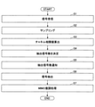
次に、無線基地局4の全体の動作例を、図9のフローチャートを参照してより具体的に説明する。なお、抽出信号数決定に関わる処理と、実処理(通信サービス提供のための処理)と並行して実行される。従って、抽出信号数は、通信サービス提供中に随時変更され得る。また、抽出信号数決定に関わる処理と、実処理(通信サービス提供のための処理)とは別々に行うこととしてもよい。この場合、予め抽出信号数決定に関わる処理を行って抽出信号数を決定し、その後に実処理を行う。また、前述したタイミング同期に関する動作は、実処理(通信サービス提供のための処理)と並行して実行される。
次に、無線基地局4の全体の動作例を、図9のフローチャートを参照してより具体的に説明する。なお、抽出信号数決定に関わる処理と、実処理(通信サービス提供のための処理)と並行して実行される。従って、抽出信号数は、通信サービス提供中に随時変更され得る。また、抽出信号数決定に関わる処理と、実処理(通信サービス提供のための処理)とは別々に行うこととしてもよい。この場合、予め抽出信号数決定に関わる処理を行って抽出信号数を決定し、その後に実処理を行う。また、前述したタイミング同期に関する動作は、実処理(通信サービス提供のための処理)と並行して実行される。
アンテナ制御部23は、同期部32から受信するアンテナ特性切替周期及びタイミング情報に同期させたアンテナ制御信号を特性可変アンテナ20に出力し、特性可変アンテナ20は、当該アンテナ制御信号に従って、アンテナ特性を周期的に切り替えている。
<S1>
S1(ステップ1)において、特性可変アンテナ20が無線端末局1の複数のアンテナから同時に送信された信号を受信する。受信した信号は第1RF部21に入力され、第1RF部21からE/O変換部28に入力され、E/O変換部28により電気信号が光信号に変換され、変換された光信号が光ファイバ30により伝送され、O/E変換部29に入力される。
S1(ステップ1)において、特性可変アンテナ20が無線端末局1の複数のアンテナから同時に送信された信号を受信する。受信した信号は第1RF部21に入力され、第1RF部21からE/O変換部28に入力され、E/O変換部28により電気信号が光信号に変換され、変換された光信号が光ファイバ30により伝送され、O/E変換部29に入力される。
O/E変換部29は、光信号を電気信号に変換し、第2RF部31に出力する。第2RF部31により処理された信号はA/D変換部22に出力される。
<S2>
S2において、A/D変換部22は、入力された信号(アナログ信号)に対してサンプリングを行って、サンプリングされた信号(デジタル信号)を取得する。A/D変換部22により得られた信号は、信号抽出部24及び指標値算出部26に出力される。なお、同期部32による調整により、アンテナ特性の変化のタイミングとサンプリングのタイミングは同期している。
S2において、A/D変換部22は、入力された信号(アナログ信号)に対してサンプリングを行って、サンプリングされた信号(デジタル信号)を取得する。A/D変換部22により得られた信号は、信号抽出部24及び指標値算出部26に出力される。なお、同期部32による調整により、アンテナ特性の変化のタイミングとサンプリングのタイミングは同期している。
<S3>
S3において、指標値算出部26は、アンテナ制御部23から入力されるアンテナの制御情報に基づいて、A/D変換部22から入力される信号からそれぞれのアンテナ特性における伝搬チャネル応答を算出するとともに、特性可変アンテナ20で設定されるアンテナ特性間の伝搬チャネル応答の相関値(チャネル相関値)を算出する。
S3において、指標値算出部26は、アンテナ制御部23から入力されるアンテナの制御情報に基づいて、A/D変換部22から入力される信号からそれぞれのアンテナ特性における伝搬チャネル応答を算出するとともに、特性可変アンテナ20で設定されるアンテナ特性間の伝搬チャネル応答の相関値(チャネル相関値)を算出する。
指標値算出部26は、アンテナ特性間の伝搬チャネル応答の相関値を、例えは下記の式1により算出する。
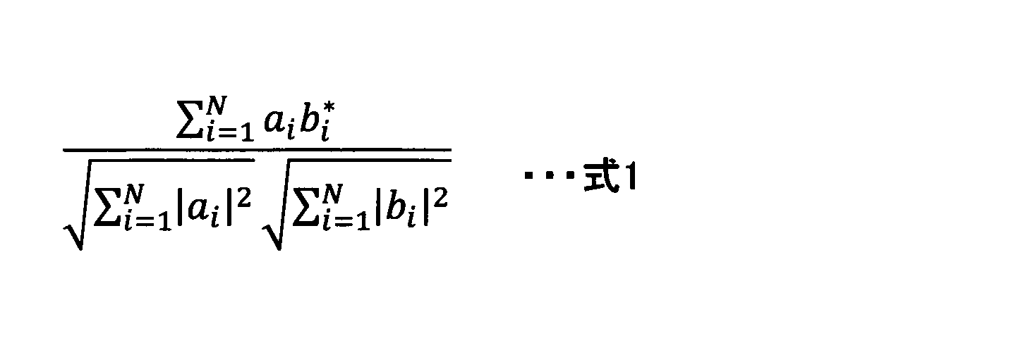
例えば、特性可変アンテナ20が4つのアンテナ特性を切り替えているとし、それぞれの特性におけるアンテナを仮想アンテナ1、仮想アンテナ2、仮想アンテナ3、仮想アンテナ4と呼ぶこととする。
この場合、指標値算出部26は、仮想アンテナ1と仮想アンテナ2との間のチャネル相関値、仮想アンテナ1と仮想アンテナ3との間のチャネル相関値、仮想アンテナ1と仮想アンテナ4との間のチャネル相関値、仮想アンテナ2と仮想アンテナ3との間のチャネル相関値、仮想アンテナ2と仮想アンテナ4との間のチャネル相関値、仮想アンテナ3と仮想アンテナ4との間のチャネル相関値を算出し、これらのチャネル相関値の和を求めることで、仮想アンテナ1~4間のチャネル相関値を算出する。
また、抽出信号数の算出方法に応じて、上記のような2仮想アンテナ間での各チャネル相関値、仮想アンテナ1~4間のチャネル相関値に加えて、仮想アンテナ1、2、3間のチャネル相関値、仮想アンテナ1、2、4間のチャネル相関値、仮想アンテナ2、3、4間のチャネル相関値を算出してもよい。つまり、全ての組み合わせについてのチャネル相関値を算出してもよい。
<S4>
S4において、抽出信号数決定部27は、指標値算出部26から入力されるチャネル相関値に基づいて抽出信号数を算出し、算出結果を信号抽出部24に出力する。
S4において、抽出信号数決定部27は、指標値算出部26から入力されるチャネル相関値に基づいて抽出信号数を算出し、算出結果を信号抽出部24に出力する。
例えば、抽出信号数決定部27は、事前にシミュレーションもしくは実測で算出したチャネル相関値と伝送容量の関係性を示すテーブルを保持しており、指標値算出部26により算出されたチャネル相関値に基づきテーブルを参照し、伝送容量の劣化量がしきい値以下となる最小の抽出信号数を決定する。しきい値は、事前に与えておく値である。
「伝送容量の劣化量がしきい値以下となる最小の抽出信号数」の意味は下記のとおりである。
抽出信号数が多いほど(つまり、MIMO信号復調部25へ入力される信号の受信に使用される仮想アンテナの数が多いほど)、伝送容量が大きくなるが、抽出信号数が大きくなり過ぎるとMIMO信号復調部25の処理負荷が過大になる。抽出信号数の増加に対する伝送容量の増加の度合いは、抽出信号数が大きいほど小さくなる。例えば、抽出信号数が16から18に増加する場合の伝送容量の増加量は、抽出信号数が10から12に増加する場合の伝送容量の増加量よりも小さい。
つまり、切り替えに使用される仮想アンテナ数と等しい抽出信号数(便宜上Nとする)を用いた場合の伝送容量に比べて、Nよりも小さい抽出信号数Mにおける伝送容量は劣化する。本実施の形態では、伝送容量の劣化を小さくしつつ、MIMO信号復調部25の処理負荷が過大にならないように、「伝送容量の劣化量がしきい値以下となる最小の抽出信号数」を決定し、それを信号抽出部24へ通知することとしている。
例えば、N=16とした場合において、抽出信号数=16のときの伝送容量に対する抽出信号数=14の伝送容量の劣化量が、しきい値以下(つまり、あまり劣化しない)であり、抽出信号数=12の伝送容量の劣化量もしきい値以下であるが、抽出信号数=10の伝送容量の劣化量はしきい値を超える場合、抽出信号数=12となる。
より具体的には、例えば、抽出信号数決定部27は、切り替えながらの信号受信に使用される仮想アンテナ数毎に、図10に示すようなテーブルを保持している。図10に示すテーブルは、指標値算出部26により得られたチャネル相関値に対応する抽出信号数(=「伝送容量の劣化がしきい値以下となる最小の抽出信号数」)を、チャネル相関値毎に保持するテーブルである。
例えば、仮想アンテナ数=Nである場合に、チャネル相関値として「A」が算出された場合、抽出信号数決定部27は、自身が保持する図9のテーブルを参照することにより、抽出信号数として、「N1」を決定する。
S4において、抽出信号数決定部27は、上記のようにして抽出信号数のみを決定してもよいし、抽出信号数に加えて、その数の仮想アンテナ(どの仮想アンテナの信号を使用するか)を決定してもよい。
抽出信号数に加えて、その数の仮想アンテナも決定する場合において、抽出信号数決定部27は、例えば、その数の仮想アンテナ間のチャネル相関値が最小(相関が弱い)の仮想アンテナの組を選択(決定)する。
例えば、仮想アンテナ1~4の4つの仮想アンテナを切り替えて使用する場合において、抽出信号数=3となった場合を想定する。この場合、例えば、仮想アンテナ1、2、3間のチャネル相関値、仮想アンテナ1、2、4間のチャネル相関値、仮想アンテナ2、3、4間のチャネル相関値のうち、仮想アンテナ1、2、3間のチャネル相関値が最小になったとすると、抽出信号数決定部27は、決定した抽出信号数の仮想アンテナとして、仮想アンテナ1、2、3を決定する。
<S5>
S5において、抽出信号数決定部27は、S4で決定した抽出信号数を信号抽出部24に通知する。
S5において、抽出信号数決定部27は、S4で決定した抽出信号数を信号抽出部24に通知する。
S4で、抽出信号数に加えて、その数の仮想アンテナも決定した場合には、S5において、抽出信号数決定部27は、S4で決定した抽出信号数の仮想アンテナを信号抽出部24に通知する。
<S6>
S6において、信号抽出部24は、抽出信号数決定部27から受信した抽出信号数に基づいて、A/D変換部22から入力された信号をA/D変換部22のサンプリング周期と同じサンプリング周期で分割し、分割した信号から抽出信号数の信号を抽出(選択)し、抽出した信号をMIMO信号復調部25に出力する。
S6において、信号抽出部24は、抽出信号数決定部27から受信した抽出信号数に基づいて、A/D変換部22から入力された信号をA/D変換部22のサンプリング周期と同じサンプリング周期で分割し、分割した信号から抽出信号数の信号を抽出(選択)し、抽出した信号をMIMO信号復調部25に出力する。
なお、信号抽出部24で抽出可能な最大信号数が予め定められていてもよい。その場合、信号抽出部24に対して当該最大信号数よりも大きな抽出信号数が通知された場合には、信号抽出部24は、当該最大信号数の信号を抽出し、抽出した信号をMIMO信号復調部25に出力する。
信号抽出部24が、抽出信号数決定部27から抽出信号数のみを受信した場合、分割した信号からどの信号を抽出するかについては、特定の方法に限定されないが、例えば、どの信号を抽出するかを予め定めておくこととしてもよい。
例えば、仮想アンテナ1~4を使用する場合において、仮想アンテナ1、2、3、4の順で選択するように定められているとする。この場合、仮に抽出信号数=3であるとすると、信号抽出部24は、仮想アンテナ1~4の信号のうち、仮想アンテナ1、2、3の信号を抽出し、MIMO信号復調部25に出力する。
また、信号抽出部24が、抽出信号数決定部27から仮想アンテナの情報(抽出するべき信号の情報)を受信した場合、信号抽出部24は、分割した信号から、抽出信号数決定部27により通知された信号を抽出し、MIMO信号復調部25に出力する。
図11に、信号抽出部24による動作のイメージを示す。図11に示す例では、仮想アンテナ1~8が使用されていることを想定している。仮想アンテナ1~8に対応する信号を信号1~8とする(図では、数字の入った○が信号を示す)。
信号抽出部24は、A/D変換部22によりサンプリングされた信号を受信する。信号抽出部24は、サンプリング周期と同じ周期で、入力された信号を分割することにより、信号1、2、3、4、5、6、7、8、....を順次取得(識別)する。
図11の例では、抽出信号数決定部27から信号抽出部24に対して、信号1~8のうち、信号1、4、7、8を抽出するよう指定されているものとする。この場合、信号抽出部24は、信号1~8のうち、信号1、4、7、8を抽出し、これらの信号をMIMO信号復調部25に出力する。
<S7>
S7において、MIMO信号復調部25は、信号抽出部24から受信した信号に対して、一般的な無線通信システムで規定されるMIMOの復調処理を行う。なお、MIMO復調処理において必要となる情報(無線端末局1のアンテナ数等)は、事前に与えられていることとしてもよいし、推定することとしてもよい。
S7において、MIMO信号復調部25は、信号抽出部24から受信した信号に対して、一般的な無線通信システムで規定されるMIMOの復調処理を行う。なお、MIMO復調処理において必要となる情報(無線端末局1のアンテナ数等)は、事前に与えられていることとしてもよいし、推定することとしてもよい。
(チャネル相関値以外の指標値例)
上記の例では、抽出信号数の決定のための指標値として、仮想アンテナ間のチャネル相関値を用いているが、これは一例である。チャネル相関値以外の指標値を用いて抽出信号数を決定してもよい。
上記の例では、抽出信号数の決定のための指標値として、仮想アンテナ間のチャネル相関値を用いているが、これは一例である。チャネル相関値以外の指標値を用いて抽出信号数を決定してもよい。
例えば、図9のフローのS3において、指標値算出部26は、チャネル指標値に代えて、下記の式2により、使用している仮想アンテナに基づく理論的な伝送容量Cを算出する。
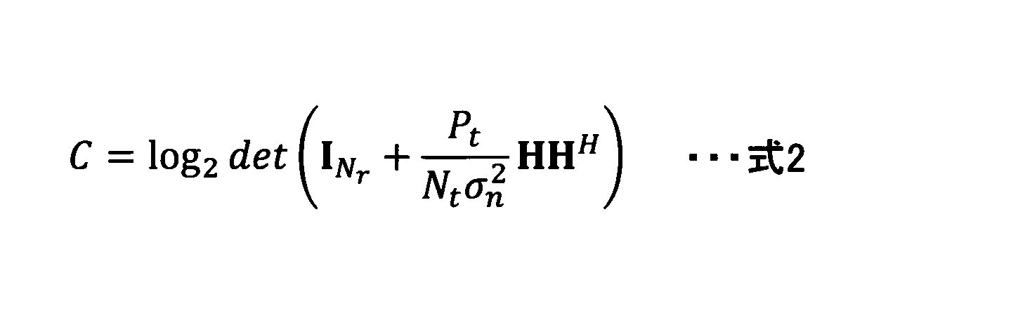
例えば、特性可変アンテナ20が4つのアンテナ特性を切り替えているとする。つまり、仮想アンテナ1、仮想アンテナ2、仮想アンテナ3、仮想アンテナ4を使用しているとする。
この場合、指標値算出部26は、式2を用いて、仮想アンテナ1~4を使用した場合の伝送容量を算出する。
また、抽出信号数の算出方法に応じて、上記のような全仮想アンテナを用いた場合の伝送容量に加えて、仮想アンテナ1と仮想アンテナ2を使用した場合の伝送容量、仮想アンテナ1と仮想アンテナ3を使用した場合の伝送容量、仮想アンテナ1と仮想アンテナ4を使用した場合の伝送容量、仮想アンテナ2と仮想アンテナ3を使用した場合の伝送容量、仮想アンテナ2と仮想アンテナ4を使用した場合の伝送容量、仮想アンテナ3と仮想アンテナ4を使用した場合の伝送容量、仮想アンテナ1、2、3を使用した場合の伝送容量、仮想アンテナ1、2、4を使用した場合の伝送容量、仮想アンテナ2、3、4を使用した場合の伝送容量を算出してもよい。つまり、全ての組み合わせについての伝送容量を算出してもよい。
S4において、抽出信号数決定部27は、指標値算出部26から入力される伝送容量から抽出信号数を算出し、算出結果を信号抽出部24に出力する。
例えば、抽出信号数決定部27は、伝送容量と「伝送容量の劣化がしきい値以下となる最小の抽出信号数」とを対応付けたテーブルを、使用する仮想アンテナの数毎に保持している。
ここで、仮想アンテナ数=Nに対応するテーブルにおける、伝送容量Cに対応する「伝送容量の劣化がしきい値以下となる最小の抽出信号数」が「N1」であるとする。
このとき、式2による計算で伝送容量としてCが算出された場合、抽出信号数決定部27は、テーブルを参照することにより、抽出信号数として「N1」を決定する。
S4において、抽出信号数決定部27は、上記のようにして抽出信号数のみを決定してもよいし、抽出信号数に加えて、その数の仮想アンテナ(どの仮想アンテナの信号を使用するか)を決定してもよい。
抽出信号数に加えて、その数の仮想アンテナも決定する場合において、抽出信号数決定部27は、例えば、その数の仮想アンテナの伝送容量が最大となる仮想アンテナの組を選択(決定)する。
例えば、仮想アンテナ1~4の4つの仮想アンテナを切り替えて使用する場合において、抽出信号数=3となった場合を想定する。この場合、例えば、仮想アンテナ1、2、3での伝送容量、仮想アンテナ1、2、4での伝送容量、仮想アンテナ2、3、4での伝送容量のうち、仮想アンテナ1、2、3での伝送容量が最大になったとすると、抽出信号数決定部27は、決定した抽出信号数の仮想アンテナとして、仮想アンテナ1、2、3を決定する。
指標値として、これまでに説明したチャネル相関値、伝送容量の他に、例えば、固有値、あるいは、受信電力対雑音電力比(SNR)を用いてもよい。固有値とは、上記のチャネル行列Hを固有値分解して得られる固有値であり、各空間伝送に対する受信電力に相当する値である。また、受信電力対雑音電力比(SNR)は、上記の固有値を雑音電力で割った値である。
(変形例)
以上、基本的な構成を基本例として説明したが、更なる特性改善のために、下記の変形例1~6に説明するような構成及び動作を採用することとしてもよい。変形例1~5のうちの一部又は全部を組み合わせてもよい。また、変形例1~5において説明していない部分は、基本例が適用される。
以上、基本的な構成を基本例として説明したが、更なる特性改善のために、下記の変形例1~6に説明するような構成及び動作を採用することとしてもよい。変形例1~5のうちの一部又は全部を組み合わせてもよい。また、変形例1~5において説明していない部分は、基本例が適用される。
<変形例1>
変形例1では、A/D変換部22がオーバーサンプリングをすることにより、前述した基本例での標本化よりも細かく標本化を実行し、それらの信号の合成によって、標本化の周期よりも少ない周期の信号を発生させる。信号の合成は、信号抽出部24により行われる。信号合成後の処理は基本例の処理と同じである。
変形例1では、A/D変換部22がオーバーサンプリングをすることにより、前述した基本例での標本化よりも細かく標本化を実行し、それらの信号の合成によって、標本化の周期よりも少ない周期の信号を発生させる。信号の合成は、信号抽出部24により行われる。信号合成後の処理は基本例の処理と同じである。
変形例1における信号処理のイメージを図12に示す。図12に示す例において、所定の周期で、仮想アンテナが1、2、3、4、...のように切り替えられており、各周期の時間で、該当の仮想アンテナによりアナログ信号が得られている。
A/D変換部22が、仮想アンテナの切り替えの速さの2倍の速さでサンプリングを行うとすると、図12に示すように、1つの仮想アンテナを使用している時間内で、2つのデジタル信号がサンプリングされる。信号抽出部24は、仮想アンテナ1の信号として、信号Aと信号Bを合成した信号を生成する。他の仮想アンテナについても同様である。
<変形例2>
変形例2では、アンテナ制御部23からの制御情報に基づいて、特性可変アンテナ20が、周期的に同じ特性が所定数連続するように特性の切り替えを行う。所定数=2の場合、切り替えタイミング(=サンプリングタイミング)毎に、仮想アンテナ1、仮想アンテナ1、仮想アンテナ2、仮想アンテナ2、....のような特性となる。
変形例2では、アンテナ制御部23からの制御情報に基づいて、特性可変アンテナ20が、周期的に同じ特性が所定数連続するように特性の切り替えを行う。所定数=2の場合、切り替えタイミング(=サンプリングタイミング)毎に、仮想アンテナ1、仮想アンテナ1、仮想アンテナ2、仮想アンテナ2、....のような特性となる。
この場合、A/D変換部22は、サンプリングにより、信号1、信号1、信号2、信号2、...、のように、隣り合う信号が周期的に同じになるような信号列を出力する。
この場合の信号抽出部24における処理のイメージを図13に示す。図13の例では、例えば、信号1~8のうち、信号1~4を抽出する場合を想定している。図13に示すように、信号抽出部24は、隣り合う信号を合成し、合成した信号をMIMO信号復調部25に出力する。この機能によって、信号対雑音電力比の向上が期待できる。
<変形例3>
変形例3では、図5におけるアンテナ制御部23に対して、異なるアンテナ制御パタン(仮想アンテナの組)をそれぞれ設定し、それぞれのアンテナ制御パタンで指標値算出部26において指標値(例:チャネル相関、伝送容量)を算出する。
変形例3では、図5におけるアンテナ制御部23に対して、異なるアンテナ制御パタン(仮想アンテナの組)をそれぞれ設定し、それぞれのアンテナ制御パタンで指標値算出部26において指標値(例:チャネル相関、伝送容量)を算出する。
指標値算出部26において指標値を算出する際には、前述した基本例と同じ算出方法を用いてもよいし、波長分散等の光ファイバ特有の劣化量をノイズとして設定して指標値を算出してもよい。光ファイバ特有の劣化量をノイズとして設定して指標値を算出する際には、例えば、当該ノイズを設定して伝搬チャネル応答を算出し、その伝搬チャネル応答を用いて指標値(例:チャネル相関、伝送容量)を算出する。
光ファイバ特有の劣化量は、O/E変換部29から指標値算出部26に通知されてもよいし、指標値算出部26に予め設定されていてもよい。
指標値としてチャネル相関値を使用する場合、複数のアンテナ制御パタンのうち、チャネル相関値が最小となるアンテナ制御パタンをアンテナ制御部23に設定する。指標値として伝送容量を使用する場合、複数のアンテナ制御パタンのうち、伝送容量が最大となるアンテナ制御パタンをアンテナ制御部23に設定する。アンテナ制御パタンの決定、及びアンテナ制御部23への設定は、指標値算出部26が行ってもよいし、無線基地局2の外部にある装置が行ってもよい。また、アンテナ制御部23への設定は、無線で行ってもよいし、有線(電気、光)で行ってもよい。変形例3により、伝送容量の改善が可能となる。
例えば、アンテナ制御部23からの制御により実現可能な特性可変アンテナ20のアンテナ特性として、アンテナ特性1~10(仮想アンテナ1~10)があるとする。このときに、例えば、5個のアンテナ特性を切り替えて信号受信を行うものとする。つまり、実現可能な10本の仮想アンテナのうち、5本の仮想アンテナを用いて信号受信を行うものとする。
この場合、アンテナ特性を1~10の数字で表すとすると、変形例3では、例えば、アンテナ制御パタンA={1、2、3、4、5}、アンテナ制御パタンB={6、7、8、9、10}、アンテナ制御パタンC={2、3、4、5、6}、アンテナ制御パタンD={4、5、6、10}、....のようにして、複数のアンテナ制御パタンを作成し、アンテナ制御部23に設定する。
アンテナ制御部23は、各アンテナ制御パタンにて、特性可変アンテナ20に、アンテナ特性を切り替えながら信号受信を行わせる。例えば、アンテナ制御パタンAが適用される場合、アンテナ特性が1、2、3、4、5のように切り替えられる。そして、指標値算出部26が、各アンテナ制御パタンでの指標値を算出し、指標値に基づいて、1つのアンテナ制御パタンを決定する。
<変形例4>
変形例4では、図5における抽出信号数決定部27において、抽出信号数の上限をMIMO信号復調部25で計算可能な数に制限する。これにより、計算負荷を抑えることができる。
変形例4では、図5における抽出信号数決定部27において、抽出信号数の上限をMIMO信号復調部25で計算可能な数に制限する。これにより、計算負荷を抑えることができる。
例えば、MIMO信号復調部25で計算可能な数の上限(最大値)が16であるとした場合、基本例で説明した処理により、抽出信号数決定部27が抽出信号数=20との結果を得た場合でも、抽出信号数決定部27は、最終的な算出結果として、16をMIMO信号復調部25に通知する。
<変形例5>
本実施の形態にように、特性可変アンテナ20で受信した信号を光信号として光ファイバ30で伝送する場合、伝送距離が延びることで、光ファイバ30における波長分散等の非線形の効果で信号が劣化する。
本実施の形態にように、特性可変アンテナ20で受信した信号を光信号として光ファイバ30で伝送する場合、伝送距離が延びることで、光ファイバ30における波長分散等の非線形の効果で信号が劣化する。
そこで、変形例5では、抽出信号数決定部27は、伝搬チャネル応答等に基づく指標値(チャネル相関値、伝送容量等)から計算される抽出信号数よりも大きな抽出信号数を決定する。これにより、通信品質を向上させることができる
一例として、抽出信号数決定部27は、指標値から得られた抽出信号数と、追加するべき信号数とを対応付けたテーブルを保持している。このテーブルは、光ファイバ30の長さ、あるいは事前のシミュレーション等により、予め作成しておくものである。例えば、指標値から得られた抽出信号数が10となった場合、テーブルから10に対応する値として2が得られたとすると、抽出信号数決定部27は、最終的な抽出信号数として12を決定する。
一例として、抽出信号数決定部27は、指標値から得られた抽出信号数と、追加するべき信号数とを対応付けたテーブルを保持している。このテーブルは、光ファイバ30の長さ、あるいは事前のシミュレーション等により、予め作成しておくものである。例えば、指標値から得られた抽出信号数が10となった場合、テーブルから10に対応する値として2が得られたとすると、抽出信号数決定部27は、最終的な抽出信号数として12を決定する。
(実施の形態の効果)
本実施の形態に係る技術により、送信装置の複数のアンテナから同一周波数かつ同一時刻に送信されるMIMO信号を受信する特性可変アンテナを備える光伝送装置と、信号処理装置とが光ファイバで接続される受信装置において、特性可変アンテナのアンテナ特性の切り替えのタイミングとサンプリングのタイミングとを同期させることができる。
本実施の形態に係る技術により、送信装置の複数のアンテナから同一周波数かつ同一時刻に送信されるMIMO信号を受信する特性可変アンテナを備える光伝送装置と、信号処理装置とが光ファイバで接続される受信装置において、特性可変アンテナのアンテナ特性の切り替えのタイミングとサンプリングのタイミングとを同期させることができる。
(実施の形態のまとめ)
本明細書には、少なくとも下記の各項に記載した受信装置、信号処理装置、受信方法、及びプログラムが記載されている。
(第1項)
複数のアンテナから送信されたMIMO信号を、アンテナ特性を切り替えながら受信する特性可変アンテナと、
前記特性可変アンテナにより受信した受信信号を電気信号から光信号に変換する電気光変換部と、
光ファイバにより伝送された前記光信号を受信し、当該光信号を電気信号に変換する光電気変換部と、
前記光電気変換部により電気信号に変換された前記受信信号に対してサンプリングを行う変換部と、
前記変換部により得られた複数のアンテナ特性に対応する複数の信号から、信号を抽出する信号抽出部と、
前記信号抽出部から出力された信号に対してMIMO復調処理を実行するMIMO信号復調部と、
前記サンプリングの周期と、前記サンプリングのタイミングの情報と、前記特性可変アンテナにおいてアンテナ特性を切り替えるタイミングの情報とに基づいて、前記特性可変アンテナにおけるアンテナ特性の切り替えの周期とタイミングを調整する同期部と、
を備える受信装置。
(第2項)
前記同期部は、前記サンプリングのタイミングの情報と、前記特性可変アンテナにおいてアンテナ特性を切り替えるタイミングの情報とに基づいて、あるアンテナ特性で信号受信を行った時刻と前記サンプリングの時刻との間の遅延時間を算出し、当該算出した遅延時間と、前記特性可変アンテナにより受信した受信信号が前記変換部に到達するまでの遅延時間とを比較することにより、前記アンテナ特性の切り替えのタイミングを調整する
第1項に記載の受信装置。
(第3項)
前記変換部により得られた信号に基づいて、指標値を算出する指標値算出部と、
前記指標値に基づいて、抽出信号数を決定する抽出信号数決定部と、を備え、
前記信号抽出部は、前記変換部により得られた複数のアンテナ特性に対応する複数の信号から、前記抽出信号数の信号を抽出する
第1項又は第2項に記載の受信装置。
(第4項)
アンテナ特性を切り替えるための制御信号を前記特性可変アンテナに対して送信するアンテナ制御部を備え、
前記同期部は、前記サンプリングの周期と、前記サンプリングのタイミングの情報とを前記変換部から受信し、前記アンテナ特性を切り替えるタイミングの情報を前記アンテナ制御部から受信する
第1項ないし第3項のうちいずれか1項に記載の受信装置。
(第5項)
複数のアンテナから送信されたMIMO信号を、アンテナ特性を切り替えながら受信する特性可変アンテナと、前記特性可変アンテナにより受信した受信信号を電気信号から光信号に変換する電気光変換部とを備える光伝送装置から、光ファイバにより伝送された前記光信号を受信し、当該光信号を電気信号に変換する光電気変換部と、
前記光電気変換部により電気信号に変換された前記受信信号に対してサンプリングを行う変換部と、
前記変換部により得られた複数のアンテナ特性に対応する複数の信号から、信号を抽出する信号抽出部と、
前記信号抽出部から出力された信号に対してMIMO復調処理を実行するMIMO信号復調部と、
前記サンプリングの周期と、前記サンプリングのタイミングの情報と、前記特性可変アンテナにおいてアンテナ特性を切り替えるタイミングの情報とに基づいて、前記特性可変アンテナにおけるアンテナ特性の切り替えの周期とタイミングを調整する同期部と
を備える信号処理装置。
(第6項)
前記同期部は、前記サンプリングのタイミングの情報と、前記特性可変アンテナにおいてアンテナ特性を切り替えるタイミングの情報とに基づいて、あるアンテナ特性で信号受信を行った時刻と前記サンプリングの時刻との間の遅延時間を算出し、当該算出した遅延時間と、前記特性可変アンテナにより受信した受信信号が前記変換部に到達するまでの遅延時間とを比較することにより、前記アンテナ特性の切り替えのタイミングを調整する
第5項に記載の信号処理装置。
(第7項)
特性可変アンテナを備える受信装置が実行する受信方法であって、
複数のアンテナから送信されたMIMO信号を、前記特性可変アンテナにより、アンテナ特性を切り替えながら受信するステップと、
前記特性可変アンテナにより受信した受信信号を電気信号から光信号に変換するステップと、
光ファイバにより伝送された前記光信号を電気信号に変換するステップと、
電気信号に変換された前記受信信号に対してサンプリングを行うステップと、
サンプリングにより得られた複数のアンテナ特性に対応する複数の信号から、信号を抽出するステップと、
前記抽出された信号に対してMIMO復調処理を実行するステップと、
前記サンプリングの周期と、前記サンプリングのタイミングの情報と、前記特性可変アンテナにおいてアンテナ特性を切り替えるタイミングの情報とに基づいて、前記特性可変アンテナにおけるアンテナ特性の切り替えの周期とタイミングを調整するステップと
を備える受信方法。
(第8項)
コンピュータを、第5項又は第6項に記載の信号処理装置における前記信号抽出部、前記MIMO信号復調部、及び前記同期部として機能させるためのプログラム。
本明細書には、少なくとも下記の各項に記載した受信装置、信号処理装置、受信方法、及びプログラムが記載されている。
(第1項)
複数のアンテナから送信されたMIMO信号を、アンテナ特性を切り替えながら受信する特性可変アンテナと、
前記特性可変アンテナにより受信した受信信号を電気信号から光信号に変換する電気光変換部と、
光ファイバにより伝送された前記光信号を受信し、当該光信号を電気信号に変換する光電気変換部と、
前記光電気変換部により電気信号に変換された前記受信信号に対してサンプリングを行う変換部と、
前記変換部により得られた複数のアンテナ特性に対応する複数の信号から、信号を抽出する信号抽出部と、
前記信号抽出部から出力された信号に対してMIMO復調処理を実行するMIMO信号復調部と、
前記サンプリングの周期と、前記サンプリングのタイミングの情報と、前記特性可変アンテナにおいてアンテナ特性を切り替えるタイミングの情報とに基づいて、前記特性可変アンテナにおけるアンテナ特性の切り替えの周期とタイミングを調整する同期部と、
を備える受信装置。
(第2項)
前記同期部は、前記サンプリングのタイミングの情報と、前記特性可変アンテナにおいてアンテナ特性を切り替えるタイミングの情報とに基づいて、あるアンテナ特性で信号受信を行った時刻と前記サンプリングの時刻との間の遅延時間を算出し、当該算出した遅延時間と、前記特性可変アンテナにより受信した受信信号が前記変換部に到達するまでの遅延時間とを比較することにより、前記アンテナ特性の切り替えのタイミングを調整する
第1項に記載の受信装置。
(第3項)
前記変換部により得られた信号に基づいて、指標値を算出する指標値算出部と、
前記指標値に基づいて、抽出信号数を決定する抽出信号数決定部と、を備え、
前記信号抽出部は、前記変換部により得られた複数のアンテナ特性に対応する複数の信号から、前記抽出信号数の信号を抽出する
第1項又は第2項に記載の受信装置。
(第4項)
アンテナ特性を切り替えるための制御信号を前記特性可変アンテナに対して送信するアンテナ制御部を備え、
前記同期部は、前記サンプリングの周期と、前記サンプリングのタイミングの情報とを前記変換部から受信し、前記アンテナ特性を切り替えるタイミングの情報を前記アンテナ制御部から受信する
第1項ないし第3項のうちいずれか1項に記載の受信装置。
(第5項)
複数のアンテナから送信されたMIMO信号を、アンテナ特性を切り替えながら受信する特性可変アンテナと、前記特性可変アンテナにより受信した受信信号を電気信号から光信号に変換する電気光変換部とを備える光伝送装置から、光ファイバにより伝送された前記光信号を受信し、当該光信号を電気信号に変換する光電気変換部と、
前記光電気変換部により電気信号に変換された前記受信信号に対してサンプリングを行う変換部と、
前記変換部により得られた複数のアンテナ特性に対応する複数の信号から、信号を抽出する信号抽出部と、
前記信号抽出部から出力された信号に対してMIMO復調処理を実行するMIMO信号復調部と、
前記サンプリングの周期と、前記サンプリングのタイミングの情報と、前記特性可変アンテナにおいてアンテナ特性を切り替えるタイミングの情報とに基づいて、前記特性可変アンテナにおけるアンテナ特性の切り替えの周期とタイミングを調整する同期部と
を備える信号処理装置。
(第6項)
前記同期部は、前記サンプリングのタイミングの情報と、前記特性可変アンテナにおいてアンテナ特性を切り替えるタイミングの情報とに基づいて、あるアンテナ特性で信号受信を行った時刻と前記サンプリングの時刻との間の遅延時間を算出し、当該算出した遅延時間と、前記特性可変アンテナにより受信した受信信号が前記変換部に到達するまでの遅延時間とを比較することにより、前記アンテナ特性の切り替えのタイミングを調整する
第5項に記載の信号処理装置。
(第7項)
特性可変アンテナを備える受信装置が実行する受信方法であって、
複数のアンテナから送信されたMIMO信号を、前記特性可変アンテナにより、アンテナ特性を切り替えながら受信するステップと、
前記特性可変アンテナにより受信した受信信号を電気信号から光信号に変換するステップと、
光ファイバにより伝送された前記光信号を電気信号に変換するステップと、
電気信号に変換された前記受信信号に対してサンプリングを行うステップと、
サンプリングにより得られた複数のアンテナ特性に対応する複数の信号から、信号を抽出するステップと、
前記抽出された信号に対してMIMO復調処理を実行するステップと、
前記サンプリングの周期と、前記サンプリングのタイミングの情報と、前記特性可変アンテナにおいてアンテナ特性を切り替えるタイミングの情報とに基づいて、前記特性可変アンテナにおけるアンテナ特性の切り替えの周期とタイミングを調整するステップと
を備える受信方法。
(第8項)
コンピュータを、第5項又は第6項に記載の信号処理装置における前記信号抽出部、前記MIMO信号復調部、及び前記同期部として機能させるためのプログラム。
以上、本実施の形態について説明したが、本発明はかかる特定の実施形態に限定されるものではなく、特許請求の範囲に記載された本発明の要旨の範囲内において、種々の変形・変更が可能である。
1 無線端末局
4 無線基地局
10 アンテナ
11 RF部
12 D/A変換部
13 MIMO信号生成部
20 特性可変アンテナ
21 RF部
22 A/D変換部
23 アンテナ制御部
24 信号抽出部
25 MIMO信号復調部
26 指標値算出部
27 抽出信号数決定部
28 E/O変換部
29 O/E変換部
30 光ファイバ
31 第2RF部
32 同期部
101 プロセッサ
102 メモリ
103 補助記憶装置
104 入出力装置
4 無線基地局
10 アンテナ
11 RF部
12 D/A変換部
13 MIMO信号生成部
20 特性可変アンテナ
21 RF部
22 A/D変換部
23 アンテナ制御部
24 信号抽出部
25 MIMO信号復調部
26 指標値算出部
27 抽出信号数決定部
28 E/O変換部
29 O/E変換部
30 光ファイバ
31 第2RF部
32 同期部
101 プロセッサ
102 メモリ
103 補助記憶装置
104 入出力装置
Claims (8)
- 複数のアンテナから送信されたMIMO信号を、アンテナ特性を切り替えながら受信する特性可変アンテナと、
前記特性可変アンテナにより受信した受信信号を電気信号から光信号に変換する電気光変換部と、
光ファイバにより伝送された前記光信号を受信し、当該光信号を電気信号に変換する光電気変換部と、
前記光電気変換部により電気信号に変換された前記受信信号に対してサンプリングを行う変換部と、
前記変換部により得られた複数のアンテナ特性に対応する複数の信号から、信号を抽出する信号抽出部と、
前記信号抽出部から出力された信号に対してMIMO復調処理を実行するMIMO信号復調部と、
前記サンプリングの周期と、前記サンプリングのタイミングの情報と、前記特性可変アンテナにおいてアンテナ特性を切り替えるタイミングの情報とに基づいて、前記特性可変アンテナにおけるアンテナ特性の切り替えの周期とタイミングを調整する同期部と、
を備える受信装置。 - 前記同期部は、前記サンプリングのタイミングの情報と、前記特性可変アンテナにおいてアンテナ特性を切り替えるタイミングの情報とに基づいて、あるアンテナ特性で信号受信を行った時刻と前記サンプリングの時刻との間の遅延時間を算出し、当該算出した遅延時間と、前記特性可変アンテナにより受信した受信信号が前記変換部に到達するまでの遅延時間とを比較することにより、前記アンテナ特性の切り替えのタイミングを調整する
請求項1に記載の受信装置。 - 前記変換部により得られた信号に基づいて、指標値を算出する指標値算出部と、
前記指標値に基づいて、抽出信号数を決定する抽出信号数決定部と、を備え、
前記信号抽出部は、前記変換部により得られた複数のアンテナ特性に対応する複数の信号から、前記抽出信号数の信号を抽出する
請求項1又は2に記載の受信装置。 - アンテナ特性を切り替えるための制御信号を前記特性可変アンテナに対して送信するアンテナ制御部を備え、
前記同期部は、前記サンプリングの周期と、前記サンプリングのタイミングの情報とを前記変換部から受信し、前記アンテナ特性を切り替えるタイミングの情報を前記アンテナ制御部から受信する
請求項1ないし3のうちいずれか1項に記載の受信装置。 - 複数のアンテナから送信されたMIMO信号を、アンテナ特性を切り替えながら受信する特性可変アンテナと、前記特性可変アンテナにより受信した受信信号を電気信号から光信号に変換する電気光変換部とを備える光伝送装置から、光ファイバにより伝送された前記光信号を受信し、当該光信号を電気信号に変換する光電気変換部と、
前記光電気変換部により電気信号に変換された前記受信信号に対してサンプリングを行う変換部と、
前記変換部により得られた複数のアンテナ特性に対応する複数の信号から、信号を抽出する信号抽出部と、
前記信号抽出部から出力された信号に対してMIMO復調処理を実行するMIMO信号復調部と、
前記サンプリングの周期と、前記サンプリングのタイミングの情報と、前記特性可変アンテナにおいてアンテナ特性を切り替えるタイミングの情報とに基づいて、前記特性可変アンテナにおけるアンテナ特性の切り替えの周期とタイミングを調整する同期部と
を備える信号処理装置。 - 前記同期部は、前記サンプリングのタイミングの情報と、前記特性可変アンテナにおいてアンテナ特性を切り替えるタイミングの情報とに基づいて、あるアンテナ特性で信号受信を行った時刻と前記サンプリングの時刻との間の遅延時間を算出し、当該算出した遅延時間と、前記特性可変アンテナにより受信した受信信号が前記変換部に到達するまでの遅延時間とを比較することにより、前記アンテナ特性の切り替えのタイミングを調整する
請求項5に記載の信号処理装置。 - 特性可変アンテナを備える受信装置が実行する受信方法であって、
複数のアンテナから送信されたMIMO信号を、前記特性可変アンテナにより、アンテナ特性を切り替えながら受信するステップと、
前記特性可変アンテナにより受信した受信信号を電気信号から光信号に変換するステップと、
光ファイバにより伝送された前記光信号を電気信号に変換するステップと、
電気信号に変換された前記受信信号に対してサンプリングを行うステップと、
サンプリングにより得られた複数のアンテナ特性に対応する複数の信号から、信号を抽出するステップと、
前記抽出された信号に対してMIMO復調処理を実行するステップと、
前記サンプリングの周期と、前記サンプリングのタイミングの情報と、前記特性可変アンテナにおいてアンテナ特性を切り替えるタイミングの情報とに基づいて、前記特性可変アンテナにおけるアンテナ特性の切り替えの周期とタイミングを調整するステップと
を備える受信方法。 - コンピュータを、請求項5又は6に記載の信号処理装置における前記信号抽出部、前記MIMO信号復調部、及び前記同期部として機能させるためのプログラム。
Priority Applications (2)
| Application Number | Priority Date | Filing Date | Title |
|---|---|---|---|
| PCT/JP2020/031168 WO2022038686A1 (ja) | 2020-08-18 | 2020-08-18 | 受信装置、信号処理装置、受信方法、及びプログラム |
| JP2022543851A JP7428260B2 (ja) | 2020-08-18 | 2020-08-18 | 受信装置、信号処理装置、受信方法、及びプログラム |
Applications Claiming Priority (1)
| Application Number | Priority Date | Filing Date | Title |
|---|---|---|---|
| PCT/JP2020/031168 WO2022038686A1 (ja) | 2020-08-18 | 2020-08-18 | 受信装置、信号処理装置、受信方法、及びプログラム |
Publications (1)
| Publication Number | Publication Date |
|---|---|
| WO2022038686A1 true WO2022038686A1 (ja) | 2022-02-24 |
Family
ID=80323457
Family Applications (1)
| Application Number | Title | Priority Date | Filing Date |
|---|---|---|---|
| PCT/JP2020/031168 Ceased WO2022038686A1 (ja) | 2020-08-18 | 2020-08-18 | 受信装置、信号処理装置、受信方法、及びプログラム |
Country Status (2)
| Country | Link |
|---|---|
| JP (1) | JP7428260B2 (ja) |
| WO (1) | WO2022038686A1 (ja) |
Cited By (1)
| Publication number | Priority date | Publication date | Assignee | Title |
|---|---|---|---|---|
| WO2026069587A1 (ja) * | 2024-09-27 | 2026-04-02 | ソフトバンク株式会社 | 情報処理装置、基地局およびプログラム |
-
2020
- 2020-08-18 JP JP2022543851A patent/JP7428260B2/ja active Active
- 2020-08-18 WO PCT/JP2020/031168 patent/WO2022038686A1/ja not_active Ceased
Non-Patent Citations (3)
| Title |
|---|
| MURAKAMI, TOMOKI ET AL.: "Spatiotemporal Signal Processing Technology in Future Wireless Systems", PROCEEDINGS OF THE 2019 IEICE SOCIETY CONFERENCE (COMMUNICATION 1), 13 September 2019 (2019-09-13) - 22 March 2019 (2019-03-22), JP, pages SS-1 - SS-2, XP009535301 * |
| MURAKAMI, TOMOKI; OHMIYA, RIKU; NAKAHIRA, TOSHIRO; ISHIHARA, KOICHI; HAYASHI, TAKAFUMI: "B-1-123 Proposal of Virtual Massive MIMO (VM-MIMO)", PROCEEDINGS OF THE 2019 IEICE GENERAL CONFERENCE (COMMUNICATION 1), 5 March 2019 (2019-03-05), pages 123, XP009535297 * |
| WATANABE ISSEI; NISHIMORI KENTARO; TANIGUCHI RYOTARO; MURAKAMI TOMOKI: "A proposal on propagation environmental control by a virtual massive array", 2019 INTERNATIONAL SYMPOSIUM ON ANTENNAS AND PROPAGATION (ISAP), ANTENNA BRANCH OF CHINESE INSTITUTE OF ELECTRONICS, 27 October 2019 (2019-10-27), pages 1 - 2, XP033692358 * |
Cited By (1)
| Publication number | Priority date | Publication date | Assignee | Title |
|---|---|---|---|---|
| WO2026069587A1 (ja) * | 2024-09-27 | 2026-04-02 | ソフトバンク株式会社 | 情報処理装置、基地局およびプログラム |
Also Published As
| Publication number | Publication date |
|---|---|
| JPWO2022038686A1 (ja) | 2022-02-24 |
| JP7428260B2 (ja) | 2024-02-06 |
Similar Documents
| Publication | Publication Date | Title |
|---|---|---|
| JP2003018054A (ja) | 無線通信方法及びシステム並びに通信装置 | |
| JP2018148409A (ja) | 送受信装置 | |
| JP4145240B2 (ja) | ダイバーシチ受信方法および装置 | |
| JP6860069B2 (ja) | 無線装置及び無線通信方法 | |
| WO2015196725A1 (zh) | 一种信道仿真装置及方法、计算机存储介质 | |
| CN106559126A (zh) | 信号发送方法、信号接收方法、发射端及接收端 | |
| US20250260533A1 (en) | Wireless communication control device and wireless communication control method to coordinate reference signal waveforms | |
| JP5494665B2 (ja) | 無線通信装置、無線通信方法およびプログラム | |
| JP7428260B2 (ja) | 受信装置、信号処理装置、受信方法、及びプログラム | |
| EP4024938A1 (en) | Wireless communication device and wireless communication method | |
| JP2007159130A (ja) | 分散型アンテナ移動通信システムにおける上り受信方法及び装置 | |
| WO2022038684A1 (ja) | 受信装置、受信方法、及びプログラム | |
| WO2022123630A1 (ja) | 受信装置、及び受信方法 | |
| WO2022038685A1 (ja) | 受信装置、信号処理装置、受信方法、及びプログラム | |
| JP7468665B2 (ja) | 受信装置、受信方法、及びプログラム | |
| JP2005252844A (ja) | 受信装置 | |
| JP7468667B2 (ja) | 受信装置、受信方法、プログラム、及び送信装置 | |
| JP7677079B2 (ja) | 受信装置、及び受信方法 | |
| JP5596098B2 (ja) | アンテナ合成 | |
| JP7741519B2 (ja) | 到来方向推定装置及び到来方向推定方法 | |
| JP7468666B2 (ja) | 受信装置、受信方法、プログラム、及び送信装置 | |
| JP2017147630A (ja) | アレーアンテナシステム、アレー制御方法、アンテナ装置およびアレー制御装置 | |
| KR102003877B1 (ko) | 빔 스페이스 방식의 매시브 mimo용 채널 에뮬레이터 | |
| JP7563482B2 (ja) | 受信装置、及び受信方法 | |
| JP2001223624A (ja) | 無線受信装置 |
Legal Events
| Date | Code | Title | Description |
|---|---|---|---|
| 121 | Ep: the epo has been informed by wipo that ep was designated in this application |
Ref document number: 20950252 Country of ref document: EP Kind code of ref document: A1 |
|
| ENP | Entry into the national phase |
Ref document number: 2022543851 Country of ref document: JP Kind code of ref document: A |
|
| NENP | Non-entry into the national phase |
Ref country code: DE |
|
| 122 | Ep: pct application non-entry in european phase |
Ref document number: 20950252 Country of ref document: EP Kind code of ref document: A1 |