WO2022034847A1 - 医療器具 - Google Patents
医療器具 Download PDFInfo
- Publication number
- WO2022034847A1 WO2022034847A1 PCT/JP2021/029065 JP2021029065W WO2022034847A1 WO 2022034847 A1 WO2022034847 A1 WO 2022034847A1 JP 2021029065 W JP2021029065 W JP 2021029065W WO 2022034847 A1 WO2022034847 A1 WO 2022034847A1
- Authority
- WO
- WIPO (PCT)
- Prior art keywords
- catheter
- medical device
- tip
- deformed
- wire
- Prior art date
- Legal status (The legal status is an assumption and is not a legal conclusion. Google has not performed a legal analysis and makes no representation as to the accuracy of the status listed.)
- Ceased
Links
Images







Classifications
-
- A—HUMAN NECESSITIES
- A61—MEDICAL OR VETERINARY SCIENCE; HYGIENE
- A61M—DEVICES FOR INTRODUCING MEDIA INTO, OR ONTO, THE BODY; DEVICES FOR TRANSDUCING BODY MEDIA OR FOR TAKING MEDIA FROM THE BODY; DEVICES FOR PRODUCING OR ENDING SLEEP OR STUPOR
- A61M25/00—Catheters; Hollow probes
-
- A—HUMAN NECESSITIES
- A61—MEDICAL OR VETERINARY SCIENCE; HYGIENE
- A61M—DEVICES FOR INTRODUCING MEDIA INTO, OR ONTO, THE BODY; DEVICES FOR TRANSDUCING BODY MEDIA OR FOR TAKING MEDIA FROM THE BODY; DEVICES FOR PRODUCING OR ENDING SLEEP OR STUPOR
- A61M25/00—Catheters; Hollow probes
- A61M25/01—Introducing, guiding, advancing, emplacing or holding catheters
Definitions
- the present invention relates to a medical device.
- Patent Document 1 The catheter of Patent Document 1 is thinned and has excellent flexibility. The surgeon may use a contrast-enhanced catheter to select a vascular route, then insert the catheter and perform treatment with the catheter. Therefore, the number of work steps for selecting the blood vessel route is increased, and there is a risk that workability may be reduced.
- an object of the present invention is to provide a medical device capable of easily selecting a route of a biological lumen.
- the medical device that achieves the above object is a medical device for a catheter that is housed in the lumen of a catheter introduced into the body cavity of a living body and can be taken in and out from the tip opening of the catheter, and is linear.
- the deformed portion has a base portion of the catheter and a deformed portion having a plurality of bent portions arranged on the distal end side of the base portion. The direction of the tip with respect to the axis along the opening direction can be changed.
- the deformed portion provided on the tip side of the medical device is the tip of the medical device as it protrudes from the tip opening of the catheter configured to accommodate the medical device.
- the orientation of the part can be changed. Therefore, the surgeon can change the direction of the tip of the medical device without performing the rotation operation on the proximal end side (the operator's hand side), and can easily select the path of the biological lumen. be able to.
- FIG. 3 is a perspective view showing another configuration of the medical device shown in FIG. 2.
- FIG. 2 shows another configuration of the catheter shown in FIG. 2 and shows how to use a medical device using the catheter.
- FIG. 2 shows another configuration of the catheter shown in FIG. 2 and shows how to use a medical device using the catheter.
- It is a figure which shows another structure of the medical device shown in FIG. It is a figure which shows the usage of the medical device shown in FIG. 7. It is a figure which shows the usage of the medical device shown in FIG. 7.
- FIG. 8A shows another structure of the medical device shown in FIG. 8A.
- FIG. 9A It is a figure which shows the usage of the medical device shown in FIG. 9A. It is a figure which shows the usage of the medical device shown in FIG. 9A. It is a perspective view which shows the deformed part of the medical device which concerns on the modification 1 of this invention. It is a top view which shows the deformed part of the medical device which concerns on the modification 1 of this invention. It is a side view which shows the deformed part of the medical device which concerns on the modification 2 of this invention.
- FIGS. 1 to 7 are diagrams provided for explaining the medical device set (catheter set) 1 according to the embodiment and the medical device 100 constituting the medical device set 1.
- Arrows X1-X2 also simply referred to as arrow X
- arrows Y1-Y2 also simply referred to as arrow Y
- “Width direction (depth direction)” is shown
- arrows Z1-Z2 also simply referred to as arrow Z
- the side to be inserted into the living body is referred to as “tip” or “tip side”
- the hand side of the operator is referred to as “base end” or “base end side”.
- the "tip portion” means a certain range including the tip (tip) and its periphery
- the “base end portion” means the proximal end (most proximal end) and its periphery. It shall mean a certain range including.
- FIG. 1 shows a medical device set 1 according to the present embodiment.
- the medical device set 1 has a medical device 100 and a catheter 10.
- the catheter 10 narrows a medical device (for example, a therapeutic device such as a balloon catheter or a stent delivery device) inserted into the living lumen when treating a living lumen such as a blood vessel (for example, a lower limb artery). It is configured as a so-called guiding catheter that delivers to lesions such as.
- the catheter 10 is also commonly referred to as the parent catheter.
- the medical device set 1 used in the blood vessels of the lower limbs will be described, but the living lumen in which the catheter 10 and the medical device 100 are used is not limited to the lower limb arteries, and may be, for example, cerebral arteries or coronary arteries. May be.
- the catheter 10 includes a catheter main body 11 having a lumen 11u into which a guide wire, a medical device, a medical device 100, etc. can be inserted, and a hub arranged at the proximal end of the catheter main body 11. It has 12 and.
- the catheter body 11 is made of a flexible hollow tubular member. At the tip of the catheter body 11, a tip opening 11a communicating with the lumen 11u of the catheter body 11 is formed.
- the catheter body 11 can be formed of, for example, a known resin material.
- the hub 12 has a luer taper type connector (Y connector) known in the medical field (not shown).
- the medical device 100 is housed in the lumen 11u of the catheter 10 introduced into the body cavity of the living body, and is configured to be accessible from the tip opening 11a of the catheter 10.
- the medical device 100 has a linear base 110 and a deformed portion 120 having a plurality of bent portions m1 to m3 arranged on the tip end side of the base 110. ..
- the base 110 extends along the axial direction X of the medical device 100.
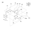
- the deformed portion 120 includes a first surface S1 including a first bent portion m1 extending from the tip end portion 100a of the base portion 110, and a base portion 110 extending from the first bent portion m1. It is formed on the second surface S2 including the second bent portion m2 provided apart from each other and the third surface S3 including the third bent portion m3 extending from the second bent portion m2 and provided apart from the base portion 110. ..
- the first surface S1 is a plane extending in the YZ plane direction
- the second surface S2 is a plane extending in the ZX plane direction
- the third surface S3 is the first surface. It is a plane different from S1 and is provided in parallel with the first surface S1. Therefore, the second surface S2 is arranged so as to intersect the first surface S1 and the third surface S3.
- the deformed portion 120 has a first bent portion m1 that bends from the axial direction X toward the height direction Z1 side.
- the deformed portion 120 is formed so as to pass through the first bent portion m1, the intermediate point P1, the intermediate point P2, and the second bent portion m2 on the first surface S1.
- the deformed portion 120 bends from the height direction Z toward the width direction Y1 at the intermediate point P1, and bends from the width direction Y toward the height direction Z1 at the intermediate point P2. Therefore, the deformed portion 120 extends in a Z shape over the sections T1 to T3 on the first surface S1, and the elasticity in the width direction Y can be ensured.
- the deformed portion 120 has a second bent portion m2 that bends from the height direction toward the axial direction X2 side.
- the deformed portion 120 is formed so as to pass through the second bent portion m2 and the third bent portion m3 on the second surface S2.
- the deformed portion 120 has a third bent portion m3 that bends from the axial direction X toward the height direction Z2 side.
- the deformed portion 120 is formed so as to pass through the third bent portion m3, the intermediate point P3, and the intermediate point P4 on the third surface S3, and the deformed portion 120 is formed at the intermediate point P3 from the height direction Z to the width direction Y1 side. It bends toward it, and at the midpoint P4, it bends from the width direction Y toward the height direction Z1.
- the deformed portion 120 extends in a U shape over the sections T3 to T5 on the second surface S2, and the elasticity in the axial direction X can be ensured. Further, the deformed portion 120 extends in a U shape over the sections T5 to T7 on the third surface S3, and can secure elasticity in the width direction Y.
- the deformed portion 120 can change the orientation of the tip portion 100a of the medical device 100 with respect to the axis (axial direction X) along the opening direction of the tip opening 11a of the catheter 10 as the catheter 10 protrudes from the tip opening 11a. It is configured in. Therefore, the deformed portion 120 changes (puts in and out) the amount of protrusion from the tip opening 11a of the catheter 10 so that the tip of the deformed portion 120 extends from the tip opening 11a as shown in FIGS. 2, 3A to 3G. The distance to the portion 100a and the direction of the tip portion 100a can be changed. As a result, the surgeon can change the direction of the tip portion 100a of the medical device 100 without performing a rotation operation on the proximal end side (the surgeon's hand side), and can select the path of the biological lumen. It can be done easily.
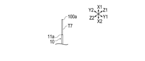
- the direction of the tip 100a of the medical device 100 is an axis with respect to the tip opening 11a (also referred to as the origin). It is on the direction X1 side.
- the base 110 and the section T7 extend on the same plane (XY plane).
- the direction of the tip 100a of the medical device 100 is the width with respect to the tip opening 11a (origin). It is on the Y1 side in the direction. At this time, the base 110 and the section T7 extend on the same plane.
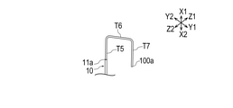
- the direction of the tip 100a of the medical device 100 is an axis with respect to the tip opening 11a (origin). It is on the direction X2 side.
- the base 110 and the section T7 extend on the same plane.
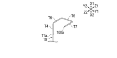
- the direction of the tip 100a of the medical device 100 is higher than the tip opening 11a (origin). It is on the Z2 side in the vertical direction. At this time, the base 110 and the section T7 extend on different planes.
- the direction of the tip 100a of the medical device 100 is an axis with respect to the tip opening 11a (origin). It is on the direction X1 side.
- the base 110 and the section T7 extend on different planes. Therefore, the base portion 110 and the section T7 are separated from each other by a distance from the second bent portion m2 to the tip portion 100a in the height direction Z, for example.
- the direction of the tip 100a of the medical device 100 is the width with respect to the tip opening 11a (origin). It is on the Y2 side.
- the base 110 and the section T7 extend on different planes. Therefore, the base portion 110 and the section T7 are separated from each other by a distance from the second bent portion m2 to the tip portion 100a in the height direction Z, for example.
- the direction of the tip 100a of the medical device 100 is an axis with respect to the tip opening 11a (origin). It is on the direction X1 side.
- the base 110 and the section T7 extend on different planes. Therefore, the base portion 110 and the section T7 are separated from each other by a distance from the second bent portion m2 to the tip portion 100a in the height direction Z, for example.
- the direction of the tip 100a of the medical device 100 is the tip opening 11a (see FIG. 2). It is on the Z1 side in the height direction with respect to the origin).
- the base 110 and the section T7 extend on different planes. Therefore, the base portion 110 and the section T7 are separated from each other by a distance from the first bent portion m1 to the tip portion 100a in the height direction Z, for example.
- the bending portion m1 to m3 is provided in a natural state, and the deformed portion 120 is formed of a wire that can be deformed in a compression direction or an expansion direction in a state of receiving an external force, and the deformation portion 120 has a shape memory. Formed of alloy.
- the deformable portion 120 formed by the deformable wire when it is inserted into the catheter 10, it is corrected along the axial direction X of the catheter 10, and when it protrudes from the tip opening 11a of the catheter 10, it deforms.
- the surgeon first inserts a general guide wire into the living body, inserts the catheter 10 as a parent catheter up to the entrance of the subclavian artery B1, removes the guide wire, and then performs medical treatment.
- a child catheter eg, rapid exchange type microcatheter
- the configuration of the medical device 100 is not limited to the above-mentioned form as long as it has a deformed portion 120 that deforms when protruding from the tip opening 11a of the catheter 10.
- the base 110A and the deformed portion 120A of the medical device 100A can be composed of a wire 200 and a catheter 300 configured to allow the wire 200 to be inserted, as shown in FIG.
- the wire 200 and the catheter 300 may be configured to be deformable, or either the wire 200 or the catheter 300 may be configured to be deformable.
- the surgeon inserts the catheter 10 to be the parent catheter to the entrance of the subclavian artery B1 (see FIG.
- the catheter 300 constituting the medical device 100 may be a rapid exchange type catheter.
- the distal end side of the catheter 10 may be configured to be deformed depending on the shape of the medical device 100 or the medical device 100A to be accommodated.
- the distal end side of the catheter 10A is at least partially deformed by the deformed portion 120A of the medical device 100A (see FIG. 6A), and when the deformed portion 120A of the medical device 100A protrudes from the distal end opening of the catheter 10A, it is substantially straight. It may be configured to have a shape (see FIG. 6B).
- the base portion 110B and the deformed portion 120B of the medical device 100B can be configured by a spring wire 600 having a tip member 620.
- the distal end side of the spring wire 600 is straightened along the axial direction X of the catheter 10 when inserted into the catheter 10, and is deformed when protruding from the distal end opening 11a of the catheter 10 (see FIG. 8A).
- the tip of the hard wire 700 comes into contact with the tip member 620.
- the spring wire 600 is straightened in a substantially linear shape in the state (see FIG. 8B.
- the spiral shape shown in FIG. 7 is simply shown as a tubular shape.
- the configuration of the spring wire 600 can be variously changed.
- the spring wire 600A constituting the base 110C and the deformed portion 120C of the medical device 100C has a tip opening 610a, and the wire 800 may be projected from the tip opening 610a. can.
- the distal end side of the spring wire 600 is straightened along the axial direction X of the catheter 10 when inserted into the catheter 10, and is deformed when protruding from the distal end opening 11a of the catheter 10 (see FIG. 10A). ).
- the spring wire 600A when the operator inserts the wire 800 along the spring wire 600 and retracts only the spring wire 600 toward the proximal end side, the distal end side of the wire 800 may protrude from the distal end opening 610a. (See FIG. 10B. Note that the spring wire 600A shown in FIGS. 10A and 10B is shown as a tubular shape by simplifying the spiral shape shown in FIGS. 9A and 9B).
- the second surface S2 is arranged so as to intersect with any of the first surface S1 and the third surface S3.
- the three surfaces S3 are not particularly limited as long as they are arranged so as to intersect with either the first surface S1 or the second surface S2.
- the medical device 400 has a linear base 410 and a deformation portion 420, and the deformation portions 420 are provided so as to intersect each other as shown in FIG. 11A. Even if it is formed along the four planes S4 (XY plane in the figure), the fifth plane S5 (intermediate plane between the XY plane and the XZ plane in the figure), and the sixth plane S6 (XZ plane in the figure). good.
- the deformed portion 420 may be configured to be deformed so as to spirally wind with respect to the axial direction X as the catheter 10 protrudes from the distal end opening 11a.
- the deformed portion 420 extends substantially in an annular shape on each of the fourth surface S4, the fifth surface S5, and the sixth surface S6, and the amount of protrusion from the tip opening 11a of the catheter 10 by the operator is changed (insertion / removal). By doing so, the direction of the tip portion 400a can be changed. Therefore, the surgeon can change the direction of the tip portion 400a of the medical device 400 without performing a rotation operation on the proximal end side (the surgeon's hand side), and it is easy to select the path of the biological lumen. Can be done.
- the number of planes on which the deformed portion 120 extends is not particularly limited.
- the deformed portion 120 may extend to only one plane, or may extend over a plurality of planes.
- the medical device 500 has a linear base portion 510 and a deformed portion 520, and the deformed portion 520 has a fourth plane S4 (as shown in FIG. 12). It extends only to the XY plane in the figure), and is configured to be deformed so as to bend in a bellows shape with respect to the direction intersecting the axial direction X as the catheter 10 protrudes from the tip opening 11a. You may.
- the deformed portion 520 changes the distance from the tip opening 11a to the tip 500a and the direction of the tip 500a by changing (moving in and out) the amount of protrusion of the catheter 10 from the tip opening 11a. be able to. Therefore, the operator can change the direction of the tip portion 500a of the medical device 500 without performing a rotation operation on the proximal end side (the operator's hand side), and it is easy to select the path of the biological lumen. Can be done.
- the length y1 of the deformed portion 520 in the width direction Y (the length between one bent portion and another bent portion extending from one bent portion) is as shown in FIG. It may be substantially constant from the base end side to the tip end side of the deformed portion 520, may be configured to be shorter toward the tip end side, or may be configured to be longer toward the tip end side. good.
- the medical device 100 is housed in the lumen 11u of the catheter 10 introduced into the body cavity of the living body, and is configured to be accessible from the tip opening 11a of the catheter 10 for a catheter.
- the medical device has a linear base 110 and a deformed portion 120 having a plurality of bent portions m1 to m3 arranged on the distal end side of the base 110, and the deformed portion 120 is the tip opening of the catheter 10.
- the orientation of the tip 100a with respect to the axis (axial direction X) along the opening direction of the tip opening 11a of the catheter 10 can be changed.
- the deformed portion 120 changes (puts in and out) the amount of protrusion from the tip opening 11a of the catheter 10 so that the deformed portion 120 can be inserted and removed from the tip opening 11a to the tip 100a.
- the distance to the tip 100a and the direction of the tip 100a can be changed.
- the surgeon can change the direction of the tip portion 100a of the medical device 100 without performing a rotation operation on the proximal end side (the surgeon's hand side), and can select the path of the biological lumen. It can be done easily.
- the deformed portion 520 is deformed so as to bend in a bellows shape at least partially in a direction intersecting the axis (axial direction X) with the protrusion of the catheter 10 from the tip opening 11a.
- the deformed portion 520 changes (puts in and out) the amount of protrusion from the tip opening 11a of the catheter 10 so that the distance from the tip opening 11a to the tip 500a and the direction of the tip 500a.
- the deformed portion 420 is deformed so as to spirally wind with respect to the axis (axial direction X) at least partially as the catheter 10 protrudes from the tip opening 11a. Therefore, the surgeon can change the direction of the tip portion 400a of the medical device 400 without performing a rotation operation on the proximal end side (the surgeon's hand side), and it is easy to select the path of the biological lumen. Can be done.
- the deformed portion 420 has a substantially annular shape on each of the fourth surface S4 (also referred to as the first surface), the fifth surface S5 (also referred to as the second surface), and the sixth surface S6 (also referred to as the third surface).
- the direction of the tip 400a can be changed by changing (moving in and out) the amount of the catheter 10 protruding from the tip opening 11a of the catheter 10. Therefore, the surgeon can change the direction of the tip portion 400a of the medical device 400 without performing a rotation operation on the proximal end side (the surgeon's hand side), and it is easy to select the path of the biological lumen. Can be done.
- the deformed portion 120 extends from the first surface S1 including the first bent portion m1 provided extending from the tip portion 100a of the base portion 110, and extends from the first bent portion m1 and is separated from the base portion 110. It is formed on a second surface S2 including a second bent portion m2 provided, and is characterized in that the first surface S1 and the second surface S2 intersect with each other.
- the deformed portion 120 changes (puts in and out) the amount of protrusion from the tip opening 11a of the catheter 10 so that the distance from the tip opening 11a to the tip 100a and the direction of the tip 100a. Can be changed.
- the surgeon can change the direction of the tip portion 100a of the medical device 100 without performing a rotation operation on the proximal end side (the surgeon's hand side), and can select the path of the biological lumen. It can be done easily.
- the deformed portion 120 extends from the second bent portion m2 and is formed on the third surface S3 including the third bent portion m3 provided apart from the base 110, and is formed on the first surface S1 and the second surface S2. It is characterized in that either of them intersects with the third surface S3.
- the deformed portion 120 changes (puts in and out) the amount of protrusion from the tip opening 11a of the catheter 10 so that the distance from the tip opening 11a to the tip 100a and the direction of the tip 100a. Can be changed.
- the surgeon can change the direction of the tip portion 100a of the medical device 100 without performing a rotation operation on the proximal end side (the surgeon's hand side), and can select the path of the biological lumen. It can be done easily.
- the base 110 and the deformable portion 120 are formed of a deformable wire.
- the surgeon first inserts a general guide wire into the living body, inserts the catheter 10 as a parent catheter to the entrance of the sublumen artery, and then removes the guide wire.
- a child catheter for example, a rapid exchange type microcatheter
- the base 110A and the deforming portion 120A are composed of a wire 200 and a catheter 300 configured to allow the wire 200 to be inserted, and at least one of the wire 200 and the catheter 300 is deformable, and the deforming portion 120 Has.
- the surgeon inserts the catheter 10 serving as the parent catheter to the entrance of the subclavian artery, inserts the medical device 100A, and wires along the catheter 300 used as the inner guide. By inserting the 200, the path of the biological lumen can be easily selected.
- the deformed portion 120 is formed of a shape memory alloy. Therefore, the operator can change the direction of the tip portion 100a of the medical device 100 without performing a rotation operation on the proximal end side (the operator's hand side), and it is easy to select the path of the biological lumen. Can be done.
- the medical device 100 has been described above through the embodiments, the present invention is not limited to each configuration described in the specification, and may be appropriately modified based on the description of the scope of claims. Is possible.
Landscapes
- Health & Medical Sciences (AREA)
- Life Sciences & Earth Sciences (AREA)
- Biophysics (AREA)
- Pulmonology (AREA)
- Engineering & Computer Science (AREA)
- Anesthesiology (AREA)
- Biomedical Technology (AREA)
- Heart & Thoracic Surgery (AREA)
- Hematology (AREA)
- Animal Behavior & Ethology (AREA)
- General Health & Medical Sciences (AREA)
- Public Health (AREA)
- Veterinary Medicine (AREA)
- Media Introduction/Drainage Providing Device (AREA)
Abstract
【課題】生体管腔の経路の選択を容易に行うことができる医療器具を提供する。 【解決手段】医療器具100は、生体の体腔内へ導入されるカテーテルのルーメン内に収容され、カテーテル10の先端開口部11aより出し入れ可能に構成される、カテーテル用の補助デバイスであって、直線状の基部110と、基部110の先端側に配置された複数の屈曲部m1~m3を有する変形部120を有し、変形部120は、カテーテル10の先端開口部11aからの突出に伴って、カテーテル10の先端開口部11aの開口方向に沿う軸線(軸方向X)に対する先端部100aの向きを変更可能に構成される。
Description
本発明は、医療器具に関する。
従来から、下肢のカテーテル治療において、鎖骨下動脈等から医療器具を送達させて治療を行う手技が知られている(例えば、特許文献1を参照)。医師等の術者は、医療器具を送達する際の医療器具の送達のし易さや患者への負担等を考慮して適切な経路を選択する必要がある。
しかしながら、医療器具の送達のし易さは、例えば、経路を構成する生体管腔(例えば、血管)の屈曲や湾曲の大きさに応じて変化する。そのため、術者にとって、適切な血管の経路を選択する作業が大きな負担となるという問題がある。
特許文献1のカテーテルは、薄肉化され、柔軟性に優れている。術者は、造影カテーテルを用いて血管の経路を選択してから、該カテーテルを挿入し、該カテーテルを用いて治療を行う場合がある。そのため、血管の経路を選択するための作業工程が多くなり、作業性が低下してしまう虞がある。
そこで、本発明は、生体管腔の経路の選択を容易に行うことができる医療器具を提供することを目的とする。
上記目的を達成する医療器具は、生体の体腔内へ導入されるカテーテルのルーメン内に収容され、前記カテーテルの先端開口部より出し入れ可能に構成される、カテーテル用の医療器具であって、直線状の基部と、前記基部の先端側に配置された複数の屈曲部を有する変形部を有し、前記変形部は、前記カテーテルの先端開口部からの突出に伴って、前記カテーテルの先端開口部の開口方向に沿う軸線に対する先端部の向きを変更可能に構成される。
上記のように構成した医療器具によれば、医療器具の先端側に設けられた変形部は、医療器具を収容可能に構成されるカテーテルの先端開口部からの突出に伴って、医療器具の先端部の向きを変更することができる。そのため、術者は、基端側(術者の手元側)での回転操作を行うことなく、医療器具の先端部の方向を変更することができ、生体管腔の経路の選択を容易に行うことができる。
以下、添付した図面を参照しながら、本発明の実施形態を説明する。なお、以下の記載は特許請求の範囲に記載される技術的範囲や用語の意義を限定するものではない。また、図面の寸法比率は説明の都合上誇張されており、実際の比率とは異なる場合がある。
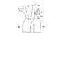
図1~図7は、実施形態に係る医療器具セット(カテーテルセット)1、および医療器具セット1を構成する医療器具100の説明に供する図である。各図に示す矢印X1-X2(単に矢印Xともいう)は、医療器具セット1の「長手方向(軸方向)」を示し、矢印Y1-Y2(単に矢印Yともいう)は、医療器具セット1の「幅方向(奥行方向)」を示し、矢印Z1-Z2(単に矢印Zともいう)は、医療器具セット1の「高さ方向」を示す。
なお、本明細書では、生体内に挿入する側を「先端」若しくは「先端側」、術者の手元側を「基端」若しくは「基端側」と称する。また、明細書の説明において「先端部」とは、先端(最先端)およびその周辺を含む一定の範囲を意味し、「基端部」とは、基端(最基端)およびその周辺を含む一定の範囲を意味するものとする。
(医療器具セット)
図1は、本実施形態に係る医療器具セット1を示す。
図1は、本実施形態に係る医療器具セット1を示す。
図1に示すように、医療器具セット1は、医療器具100と、カテーテル10と、を有している。
カテーテル10は、血管(例えば、下肢動脈)等の生体管腔の治療などを行う際に、生体管腔に挿入される医療デバイス(例えば、バルーンカテーテル、ステントデリバリーデバイス等の治療デバイス)を狭窄部等の病変部まで送達する、いわゆるガイディングカテーテルとして構成している。カテーテル10は、一般的に、親カテーテルとも称される。なお、以下において、下肢の血管で使用される医療器具セット1について説明するが、カテーテル10および医療器具100が使用される生体管腔は下肢動脈に限定されず、例えば、脳動脈や冠動脈であってもよい。
(カテーテル)
図1に示すように、カテーテル10は、ガイドワイヤ、医療デバイスや医療器具100等を挿入可能なルーメン11uが形成されたカテーテル本体部11と、カテーテル本体部11の基端部に配置されたハブ12と、を有している。
図1に示すように、カテーテル10は、ガイドワイヤ、医療デバイスや医療器具100等を挿入可能なルーメン11uが形成されたカテーテル本体部11と、カテーテル本体部11の基端部に配置されたハブ12と、を有している。
カテーテル本体部11は、可撓性を備える中空の管状部材で形成している。カテーテル本体部11の先端には、カテーテル本体部11のルーメン11uに連通する先端開口部11aが形成されている。カテーテル本体部11は、例えば、公知の樹脂材料で形成できる。
ハブ12は、医療分野において公知のルアーテーパー型のコネクタ(Yコネクタ)を有している(図示省略)。
(医療器具)
医療器具100は、生体の体腔内へ導入されるカテーテル10のルーメン11u内に収容され、カテーテル10の先端開口部11aより出し入れ可能に構成される。
医療器具100は、生体の体腔内へ導入されるカテーテル10のルーメン11u内に収容され、カテーテル10の先端開口部11aより出し入れ可能に構成される。
医療器具100は、図1、図2に示すように、直線状の基部110と、基部110の先端側に配置された複数の屈曲部m1~m3を有する変形部120と、を有している。
基部110は、図2に示すように、医療器具100の軸方向Xに沿って延在している。
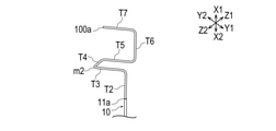
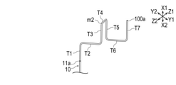
変形部120は、図2に示すように、基部110の先端部100aから延在して設けられる第1屈曲部m1を含む第1面S1と、第1屈曲部m1から延在し基部110と離間して設けられる第2屈曲部m2を含む第2面S2と、第2屈曲部m2から延在し基部110と離間して設けられる第3屈曲部m3を含む第3面S3に形成される。
図2に示すように、第1面S1は、YZ平面方向に延在する平面であり、第2面S2は、ZX平面方向に延在する平面であり、第3面S3は、第1面S1と異なる平面であって、第1面S1と平行して設けられる平面である。そのため、第2面S2は、第1面S1および第3面S3と交差するように配置されている。
また、変形部120は、図2に示すように、軸方向Xから高さ方向Z1側にむかって屈曲する第1屈曲部m1を有している。変形部120は、第1面S1において、第1屈曲部m1、中間点P1、中間点P2、第2屈曲部m2を通るように形成される。
変形部120は、中間点P1において高さ方向Zから幅方向Y1側にむかって屈曲し、中間点P2において幅方向Yから高さ方向Z1側にむかって屈曲する。そのため、変形部120は、第1面S1において、区間T1~T3にわたってZ字状に延在し、幅方向Yの弾力性を確保することができる。
変形部120は、図2に示すように、高さ方向から軸方向X2側にむかって屈曲する第2屈曲部m2を有している。変形部120は、第2面S2において、第2屈曲部m2、第3屈曲部m3を通るように形成される。
変形部120は、図2に示すように、軸方向Xから高さ方向Z2側にむかって屈曲する第3屈曲部m3を有している。変形部120は、第3面S3において、第3屈曲部m3、中間点P3、中間点P4を通るように形成され、変形部120は、中間点P3において高さ方向Zから幅方向Y1側にむかって屈曲し、中間点P4において幅方向Yから高さ方向Z1側にむかって屈曲する。
そのため、変形部120は、第2面S2において、区間T3~T5にわたってU字状に延在し、軸方向Xの弾力性を確保することができる。また、変形部120は、第3面S3において、区間T5~T7にわたってU字状に延在し、幅方向Yの弾力性を確保することができる。
変形部120は、カテーテル10の先端開口部11aからの突出に伴って、カテーテル10の先端開口部11aの開口方向に沿う軸線(軸方向X)に対する医療器具100の先端部100aの向きを変更可能に構成されている。そのため、変形部120は、術者がカテーテル10の先端開口部11aから突出させる量を変更する(出し入れする)ことによって、図2、図3A~図3Gに示すように、先端開口部11aから先端部100aまでの距離や、先端部100aの方向を変更することができる。これにより、術者は、基端側(術者の手元側)での回転操作を行うことなく、医療器具100の先端部100aの方向を変更することができ、生体管腔の経路の選択を容易に行うことができる。
例えば、術者がカテーテル10の先端開口部11aから区間T7を突出させた場合(図3Aを参照)、医療器具100の先端部100aの方向は先端開口部11a(原点ともいう)に対して軸方向X1側となる。このとき、基部110と区間T7は、同じ平面(XY平面)上に延在している。
また、術者がカテーテル10の先端開口部11aから区間T6~7を突出させた場合(図3Bを参照)、医療器具100の先端部100aの方向は先端開口部11a(原点)に対して幅方向Y1側となる。このとき、基部110と区間T7は、同じ平面上に延在している。
また、術者がカテーテル10の先端開口部11aから区間T5~7を突出させた場合(図3Cを参照)、医療器具100の先端部100aの方向は先端開口部11a(原点)に対して軸方向X2側となる。このとき、基部110と区間T7は、同じ平面上に延在している。
また、術者がカテーテル10の先端開口部11aから区間T4~7を突出させた場合(図3Dを参照)、医療器具100の先端部100aの方向は先端開口部11a(原点)に対して高さ方向Z2側となる。このとき、基部110と区間T7は、異なる平面上に延在している。
また、術者がカテーテル10の先端開口部11aから区間T3~7を突出させた場合(図3Eを参照)、医療器具100の先端部100aの方向は先端開口部11a(原点)に対して軸方向X1側となる。このとき、基部110と区間T7は、異なる平面上に延在している。そのため、基部110と区間T7は、例えば、高さ方向Zにおいて第2屈曲部m2から先端部100aまでの距離だけ離間する。
また、術者がカテーテル10の先端開口部11aから区間T2~7を突出させた場合(図3Fを参照)、医療器具100の先端部100aの方向は先端開口部11a(原点)に対して幅方向Y2側となる。このとき、基部110と区間T7は、異なる平面上に延在している。そのため、基部110と区間T7は、例えば、高さ方向Zにおいて第2屈曲部m2から先端部100aまでの距離だけ離間する。
また、術者がカテーテル10の先端開口部11aから区間T1~7を突出させた場合(図3Gを参照)、医療器具100の先端部100aの方向は先端開口部11a(原点)に対して軸方向X1側となる。このとき、基部110と区間T7は、異なる平面上に延在している。そのため、基部110と区間T7は、例えば、高さ方向Zにおいて第2屈曲部m2から先端部100aまでの距離だけ離間する。
また、術者がカテーテル10の先端開口部11aから基部110の先端側および区間T1~7を突出させた場合(図2を参照)、医療器具100の先端部100aの方向は先端開口部11a(原点)に対して高さ方向Z1側となる。このとき、基部110と区間T7は、異なる平面上に延在している。そのため、基部110と区間T7は、例えば、高さ方向Zにおいて第1屈曲部m1から先端部100aまでの距離だけ離間する。
医療器具100の構成材料としては、自然状態において屈曲部m1~m3を有し、外力を受けている状態において圧縮方向または拡張方向に対して変形可能なワイヤーで形成され、変形部120は形状記憶合金で形成される。
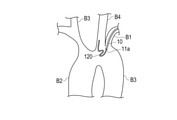
変形可能なワイヤーにより形成される変形部120によれば、カテーテル10に挿入されているときはカテーテル10の軸方向Xに沿うように矯正され、カテーテル10の先端開口部11aから突出すると変形する。術者は、下肢のカテーテル治療において、まず、一般的なガイドワイヤを生体内に挿入し、親カテーテルとなるカテーテル10を鎖骨下動脈B1の入り口まで挿入して該ガイドワイヤを抜去した後に、医療器具100を挿入し、医療器具100に沿って子カテーテル(例えば、ラピッドエクスチェンジタイプのマイクロカテーテル)を挿入することによって、生体管腔の経路(例えば、大動脈B2、B3や総頸動脈B4、B5への経路)を容易に選択することができる(図4を参照)。
なお、医療器具100の構成は、カテーテル10の先端開口部11aから突出すると変形する変形部120を有する限り、上述した形態に限定されない。例えば、医療器具100Aの基部110A及び変形部120Aは、図5に示すように、ワイヤー200と、ワイヤー200を挿通可能に構成されるカテーテル300と、により構成することができる。この場合、医療器具100Aは、ワイヤー200およびカテーテル300が変形可能に構成されていてもよく、ワイヤー200およびカテーテル300のいずれか一方が変形可能に構成されていてもよい。術者は、下肢のカテーテル治療において、親カテーテルとなるカテーテル10を鎖骨下動脈B1(図4を参照)の入り口まで挿入した後に、医療器具100Aを挿入して、インナーガイドとして使用されるカテーテル300に沿ってワイヤー200を挿入することによって、生体管腔の経路を容易に選択することができる。なお、医療器具100の構成するカテーテル300は、ラピッドエクスチェンジタイプのカテーテルであってもよい。また、カテーテル10先端側は、収容される医療器具100または医療器具100Aの形状によって変形するように構成されていてもよい。例えば、カテーテル10Aの先端側は、医療器具100Aの変形部120Aによって少なくとも部分的に変形し(図6Aを参照)、医療器具100Aの変形部120Aがカテーテル10Aの先端開口部から突出すると、略直線状になる(図6Bを参照)ように構成されていてもよい。
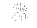
また、医療器具100Bの基部110B及び変形部120Bは、図7に示すように、先端部材620を有するスプリングワイヤー600により構成することができる。この場合、スプリングワイヤー600の先端側は、カテーテル10に挿入されているときはカテーテル10の軸方向Xに沿うように矯正され、カテーテル10の先端開口部11aから突出すると変形する(図8Aを参照)。また、カテーテル10の先端開口部11aから突出したスプリングワイヤー600の先端側は、術者がスプリングワイヤー600に沿って硬いワイヤー700を挿入すると、硬いワイヤー700の先端部が先端部材620に当接した状態で略直線状に矯正される(図8Bを参照。なお、図8Aおよび図8Bに示すスプリングワイヤー600は、図7に示す螺旋状の形状を簡略して筒状の形状で示している。)。なお、スプリングワイヤー600の構成は、種々変更することができる。例えば、図9A、図9Bに示すように、医療器具100Cの基部110C及び変形部120Cを構成するスプリングワイヤー600Aは、先端開口部610aを有し、ワイヤー800を先端開口部610aから突出させることができる。この場合、スプリングワイヤー600の先端側は、カテーテル10に挿入されているときはカテーテル10の軸方向Xに沿うように矯正され、カテーテル10の先端開口部11aから突出すると変形する(図10Aを参照)。また、スプリングワイヤー600Aは、術者がスプリングワイヤー600に沿ってワイヤー800を挿入し、スプリングワイヤー600のみを基端側へ後退させると、ワイヤー800の先端側を先端開口部610aから突出させることができる(図10Bを参照。なお、図10Aおよび図10Bに示すスプリングワイヤー600Aは、図9Aおよび図9Bに示す螺旋状の形状を簡略して筒状の形状で示している。)。
また、第1面S1、第2面S2、第3面S3の平面が延在する方向は、第2面S2が第1面S1および第3面S3のいずれかと交差するように配置され、第3面S3が第1面S1および第2面S2のいずれかと交差するように配置されている限り、特に限定されない。
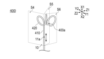
例えば、変形例1に係る医療器具400は、直線状の基部410と、変形部420と、を有し、変形部420は、図11Aに示すように、互いに交差するように設けられた、第4面S4(図中のXY平面)、第5面S5(図中のXY平面とXZ平面との中間平面)、および第6面S6(図中のXZ平面)に沿って形成されていてもよい。このとき、変形部420は、カテーテル10の先端開口部11aからの突出に伴って、軸方向Xに対して螺旋状に巻回するように変形するように構成されていてもよい。これにより、変形部420を形成する螺旋形状の第4面S4上の巻回方向であるs方向、第5面S5上の巻回方向であるt方向、第6面S6上の巻回方向であるu方向は、図11Bに示すように、互いに異なる方向となる。
変形部420は、第4面S4、第5面S5、および第6面S6のそれぞれにおいて略円環状に延在し、術者がカテーテル10の先端開口部11aから突出させる量を変更する(出し入れする)ことによって、先端部400aの方向を変更することができる。そのため、術者は、基端側(術者の手元側)での回転操作を行うことなく、医療器具400の先端部400aの方向を変更することができ、生体管腔の経路の選択を容易に行うことができる。
また、変形部120が延在する平面の個数は、特に限定されない。例えば、変形部120は、一の平面のみに延在していてもよく、複数の平面にわたって延在していてもよい。
例えば、変形例2に係る医療器具500は、直線状の基部510と、変形部520と、を有し、変形部520は、図12に示すように、一の平面である第4面S4(図中のXY平面)のみに延在し、カテーテル10の先端開口部11aからの突出に伴って、軸方向Xに交差する方向に対して蛇腹状に屈曲するように変形するように構成されていてもよい。
変形部520は、術者がカテーテル10の先端開口部11aから突出させる量を変更する(出し入れする)ことによって、先端開口部11aから先端部500aまでの距離や、先端部500aの方向を変更することができる。そのため、術者は、基端側(術者の手元側)での回転操作を行うことなく、医療器具500の先端部500aの方向を変更することができ、生体管腔の経路の選択を容易に行うことができる。
なお、変形部520の幅方向Yの長さy1(一の屈曲部と、一の屈曲部から延在して設けられる他の屈曲部と、の間の長さ)は、図12に示すように変形部520の基端側から先端側にかけて略一定であってもよく、先端側に向かって短くなるように構成されていてもよく、先端側に向かって長くなるように構成されていてもよい。
以上のように、本実施形態に係る医療器具100は、生体の体腔内へ導入されるカテーテル10のルーメン11u内に収容され、カテーテル10の先端開口部11aより出し入れ可能に構成される、カテーテル用の医療器具であって、直線状の基部110と、基部110の先端側に配置された複数の屈曲部m1~m3を有する変形部120を有し、変形部120は、カテーテル10の先端開口部11aからの突出に伴って、カテーテル10の先端開口部11aの開口方向に沿う軸線(軸方向X)に対する先端部100aの向きを変更可能に構成される。
このように構成された医療器具100によれば、変形部120は、術者がカテーテル10の先端開口部11aから突出させる量を変更する(出し入れする)ことによって、先端開口部11aから先端部100aまでの距離や、先端部100aの方向を変更することができる。これにより、術者は、基端側(術者の手元側)での回転操作を行うことなく、医療器具100の先端部100aの方向を変更することができ、生体管腔の経路の選択を容易に行うことができる。
また、変形部520は、カテーテル10の先端開口部11aからの突出に伴って、少なくとも部分的に軸線(軸方向X)に交差する方向に対して蛇腹状に屈曲するように変形する。これにより、変形部520は、術者がカテーテル10の先端開口部11aから突出させる量を変更する(出し入れする)ことによって、先端開口部11aから先端部500aまでの距離や、先端部500aの方向を変更することができる。そのため、術者は、基端側(術者の手元側)での回転操作を行うことなく、医療器具500の先端部500aの方向を変更することができ、生体管腔の経路の選択を容易に行うことができる。
また、変形部420は、カテーテル10の先端開口部11aからの突出に伴って、少なくとも部分的に軸線(軸方向X)に対して螺旋状に巻回するように変形する。そのため、術者は、基端側(術者の手元側)での回転操作を行うことなく、医療器具400の先端部400aの方向を変更することができ、生体管腔の経路の選択を容易に行うことができる。
また、変形部420を形成する螺旋形状の巻回方向(s方向、t方向、u方向)が互いに異なることを特徴とする。これにより、変形部420は、第4面S4(第1面ともいう)、第5面S5(第2面ともいう)、および第6面S6(第3面ともいう)のそれぞれにおいて略円環状に延在し、術者がカテーテル10の先端開口部11aから突出させる量を変更する(出し入れする)ことによって、先端部400aの方向を変更することができる。そのため、術者は、基端側(術者の手元側)での回転操作を行うことなく、医療器具400の先端部400aの方向を変更することができ、生体管腔の経路の選択を容易に行うことができる。
また、変形部120は、前記基部110の先端部100aから延在して設けられる第1屈曲部m1を含む第1面S1と、第1屈曲部m1から延在し、基部110と離間して設けられる第2屈曲部m2を含む第2面S2と、に形成され、第1面S1と第2面S2とが交差することを特徴とする。これにより、変形部120は、術者がカテーテル10の先端開口部11aから突出させる量を変更する(出し入れする)ことによって、先端開口部11aから先端部100aまでの距離や、先端部100aの方向を変更することができる。これにより、術者は、基端側(術者の手元側)での回転操作を行うことなく、医療器具100の先端部100aの方向を変更することができ、生体管腔の経路の選択を容易に行うことができる。
また、変形部120は、第2屈曲部m2から延在し、基部110と離間して設けられる第3屈曲部m3を含む第3面S3に形成され、第1面S1および第2面S2のいずれかと第3面S3とが交差することを特徴とする。これにより、変形部120は、術者がカテーテル10の先端開口部11aから突出させる量を変更する(出し入れする)ことによって、先端開口部11aから先端部100aまでの距離や、先端部100aの方向を変更することができる。これにより、術者は、基端側(術者の手元側)での回転操作を行うことなく、医療器具100の先端部100aの方向を変更することができ、生体管腔の経路の選択を容易に行うことができる。
また、基部110及び変形部120は、変形可能なワイヤーにより形成される。これにより、術者は、下肢のカテーテル治療において、まず、一般的なガイドワイヤを生体内に挿入し、親カテーテルとなるカテーテル10を鎖骨下動脈の入り口まで挿入して該ガイドワイヤを抜去した後に、医療器具100を挿入し、医療器具100に沿って子カテーテル(例えば、ラピッドエクスチェンジタイプのマイクロカテーテル)を挿入することによって、生体管腔の経路を容易に選択することができる。
また、基部110A及び変形部120Aは、ワイヤー200と、ワイヤー200を挿通可能に構成されるカテーテル300と、により構成され、ワイヤー200またはカテーテル300の少なくともいずれか一方は変形可能であり、変形部120を有する。これにより、術者は、下肢のカテーテル治療において、親カテーテルとなるカテーテル10を鎖骨下動脈の入り口まで挿入した後に、医療器具100Aを挿入して、インナーガイドとして使用されるカテーテル300に沿ってワイヤー200を挿入することによって、生体管腔の経路を容易に選択することができる。
また、変形部120は、形状記憶合金により形成される。そのため、術者は、基端側(術者の手元側)での回転操作を行うことなく、医療器具100の先端部100aの方向を変更することができ、生体管腔の経路の選択を容易に行うことができる。
以上、実施形態を通じて本発明に係る医療器具100を説明したが、本発明は明細書内で説明した各構成のみに限定されるものでなく、特許請求の範囲の記載に基づいて適宜変更することが可能である。
本出願は、2020年8月12日に出願された日本国特許出願第2020-136176号に基づいており、その開示内容は、参照により全体として引用されている。
1 医療器具セット、
10 カテーテル、
11 カテーテル本体部、
11a 先端開口部、
11u ルーメン、
100、100A、400、500 医療器具、
100a、400a、500a 先端部、
110、110A、410、510 基部、
120、120A、420、520 変形部、
m1 第1屈曲部、
m2 第2屈曲部、
m3 第3屈曲部、
S1 第1面、
S2 第2面、
S3 第3面。
10 カテーテル、
11 カテーテル本体部、
11a 先端開口部、
11u ルーメン、
100、100A、400、500 医療器具、
100a、400a、500a 先端部、
110、110A、410、510 基部、
120、120A、420、520 変形部、
m1 第1屈曲部、
m2 第2屈曲部、
m3 第3屈曲部、
S1 第1面、
S2 第2面、
S3 第3面。
Claims (10)
- 生体の体腔内へ導入されるカテーテルのルーメン内に収容され、前記カテーテルの先端開口部より出し入れ可能に構成される、カテーテル用の医療器具であって、
直線状の基部と、前記基部の先端側に配置された複数の屈曲部を有する変形部を有し、
前記変形部は、前記カテーテルの先端開口部からの突出に伴って、前記カテーテルの先端開口部の開口方向に沿う軸線に対する先端部の向きを変更可能に構成される、医療器具。 - 前記変形部は、前記カテーテルの先端開口部からの突出に伴って、少なくとも部分的に前記軸線に交差する方向に対して蛇腹状に屈曲するように変形する、請求項1に記載の医療器具。
- 前記変形部は、前記カテーテルの先端開口部からの突出に伴って、少なくとも部分的に前記軸線に対して螺旋状に巻回するように変形する、請求項1に記載の医療器具。
- 前記変形部を形成する螺旋形状の巻回方向が互いに異なることを特徴とする、請求項3に記載の医療器具。
- 前記変形部は、前記基部の先端部から延在して設けられる第1屈曲部を含む第1面と、前記第1屈曲部から延在し前記基部と離間して設けられる第2屈曲部を含む第2面と、に形成され、
前記第1面と前記第2面とが交差することを特徴とする、請求項1に記載の医療器具。 - 前記変形部は、前記第2屈曲部から延在し前記基部と離間して設けられる第3屈曲部を含む第3面に形成され、
前記第1面および前記第2面のいずれかと前記第3面とが交差することを特徴とする、請求項5に記載の医療器具。 - 前記基部及び前記変形部は、変形可能なワイヤーにより形成される、請求項1~6のいずれか1項に記載の医療器具。
- 前記基部及び前記変形部は、
ワイヤーと、
前記ワイヤーを挿通可能に構成されるカテーテルと、により構成され、
前記ワイヤーまたは前記カテーテルの少なくともいずれか一方は変形可能であり、前記変形部を有する、請求項1~6のいずれか1項に記載の医療器具。 - 変形可能なワイヤーと、
前記ワイヤーを挿通可能に構成され、変形可能なカテーテルと、により構成され、
前記ワイヤーおよび前記カテーテルは、前記変形部を有する、請求項8に記載の医療器具。 - 前記変形部は、形状記憶合金により形成される、請求項7~9のいずれか1項に記載の医療器具。
Applications Claiming Priority (2)
| Application Number | Priority Date | Filing Date | Title |
|---|---|---|---|
| JP2020136176A JP2023131174A (ja) | 2020-08-12 | 2020-08-12 | 医療器具 |
| JP2020-136176 | 2020-08-12 |
Publications (1)
| Publication Number | Publication Date |
|---|---|
| WO2022034847A1 true WO2022034847A1 (ja) | 2022-02-17 |
Family
ID=80247810
Family Applications (1)
| Application Number | Title | Priority Date | Filing Date |
|---|---|---|---|
| PCT/JP2021/029065 Ceased WO2022034847A1 (ja) | 2020-08-12 | 2021-08-05 | 医療器具 |
Country Status (2)
| Country | Link |
|---|---|
| JP (1) | JP2023131174A (ja) |
| WO (1) | WO2022034847A1 (ja) |
Citations (3)
| Publication number | Priority date | Publication date | Assignee | Title |
|---|---|---|---|---|
| JPH05508332A (ja) * | 1990-05-16 | 1993-11-25 | ブリガム アンド ウイミンズ ホスピタル | 管状カニューレ挿入用の操縦可能なガイドワイヤ |
| JP2001522631A (ja) * | 1997-11-07 | 2001-11-20 | プロリフィックス メディカル, インコーポレイテッド | 身体管腔内の閉塞を治療する方法およびシステム |
| US20130006262A1 (en) * | 2011-01-04 | 2013-01-03 | Merit Medical Systems, Inc. | Multiple Loop Snare |
-
2020
- 2020-08-12 JP JP2020136176A patent/JP2023131174A/ja active Pending
-
2021
- 2021-08-05 WO PCT/JP2021/029065 patent/WO2022034847A1/ja not_active Ceased
Patent Citations (3)
| Publication number | Priority date | Publication date | Assignee | Title |
|---|---|---|---|---|
| JPH05508332A (ja) * | 1990-05-16 | 1993-11-25 | ブリガム アンド ウイミンズ ホスピタル | 管状カニューレ挿入用の操縦可能なガイドワイヤ |
| JP2001522631A (ja) * | 1997-11-07 | 2001-11-20 | プロリフィックス メディカル, インコーポレイテッド | 身体管腔内の閉塞を治療する方法およびシステム |
| US20130006262A1 (en) * | 2011-01-04 | 2013-01-03 | Merit Medical Systems, Inc. | Multiple Loop Snare |
Also Published As
| Publication number | Publication date |
|---|---|
| JP2023131174A (ja) | 2023-09-22 |
Similar Documents
| Publication | Publication Date | Title |
|---|---|---|
| EP2922593B1 (en) | Preformed guidewire | |
| AU2013207563B2 (en) | Guidewire with highly flexible tip | |
| AU2010208618B2 (en) | Guidewire | |
| US5306245A (en) | Articulating device | |
| CN102844071B (zh) | 用于神经脉管应用的低剖面引导导管 | |
| EP3873350A2 (en) | Support structure for medical apparatus and method of manufacturing same | |
| JP7671291B2 (ja) | 医療装置用のガイドワイヤ | |
| JP4846236B2 (ja) | 崩壊に対する抵抗力を備える裏打ち部材を有する医療用具及びその製造方法 | |
| CN101384293A (zh) | 导丝 | |
| JPH04504368A (ja) | 操縦医療装置 | |
| CN112546402B (zh) | 能够弯曲的导丝 | |
| EP4422516A1 (en) | Agonist-antagonist tube steerable instrument with serpentine beam elements | |
| US11911004B2 (en) | Bending and extending device and bending and extending method | |
| CN115916317B (zh) | 用于控制同轴对准的机器人可操纵导丝的多自由度弯曲和弯曲长度的系统及方法 | |
| JP7555185B2 (ja) | カテーテル | |
| JP2023131174A (ja) | 医療器具 | |
| US20250345565A1 (en) | Steerable device for use inside of a mammalian body | |
| JPWO2018083905A1 (ja) | カテーテル及びカテーテル組み立て体 | |
| CN221750594U (zh) | 一种介入指引导丝组件及介入系统 | |
| JP2021078980A (ja) | カテーテル、およびカテーテルの製造方法 | |
| KR20200141582A (ko) | 가이드와이어의 조향을 위한 마이크로로봇 | |
| CN220967867U (zh) | 微导丝 | |
| JP2019150439A (ja) | ガイドワイヤ | |
| JP2025176377A (ja) | 医療器具 | |
| KR20220140330A (ko) | 스티어러블 카테터 |
Legal Events
| Date | Code | Title | Description |
|---|---|---|---|
| 121 | Ep: the epo has been informed by wipo that ep was designated in this application |
Ref document number: 21855926 Country of ref document: EP Kind code of ref document: A1 |
|
| NENP | Non-entry into the national phase |
Ref country code: DE |
|
| 122 | Ep: pct application non-entry in european phase |
Ref document number: 21855926 Country of ref document: EP Kind code of ref document: A1 |
|
| NENP | Non-entry into the national phase |
Ref country code: JP |