WO2022034840A1 - 画像処理装置及びロボット制御装置 - Google Patents
画像処理装置及びロボット制御装置 Download PDFInfo
- Publication number
- WO2022034840A1 WO2022034840A1 PCT/JP2021/028911 JP2021028911W WO2022034840A1 WO 2022034840 A1 WO2022034840 A1 WO 2022034840A1 JP 2021028911 W JP2021028911 W JP 2021028911W WO 2022034840 A1 WO2022034840 A1 WO 2022034840A1
- Authority
- WO
- WIPO (PCT)
- Prior art keywords
- exposure time
- subject
- imaging
- maximum value
- image
- Prior art date
- Legal status (The legal status is an assumption and is not a legal conclusion. Google has not performed a legal analysis and makes no representation as to the accuracy of the status listed.)
- Ceased
Links
Images


Classifications
-
- G—PHYSICS
- G06—COMPUTING OR CALCULATING; COUNTING
- G06T—IMAGE DATA PROCESSING OR GENERATION, IN GENERAL
- G06T5/00—Image enhancement or restoration
- G06T5/50—Image enhancement or restoration using two or more images, e.g. averaging or subtraction
-
- G—PHYSICS
- G06—COMPUTING OR CALCULATING; COUNTING
- G06T—IMAGE DATA PROCESSING OR GENERATION, IN GENERAL
- G06T5/00—Image enhancement or restoration
- G06T5/40—Image enhancement or restoration using histogram techniques
-
- G—PHYSICS
- G06—COMPUTING OR CALCULATING; COUNTING
- G06T—IMAGE DATA PROCESSING OR GENERATION, IN GENERAL
- G06T5/00—Image enhancement or restoration
- G06T5/90—Dynamic range modification of images or parts thereof
- G06T5/92—Dynamic range modification of images or parts thereof based on global image properties
-
- H—ELECTRICITY
- H04—ELECTRIC COMMUNICATION TECHNIQUE
- H04N—PICTORIAL COMMUNICATION, e.g. TELEVISION
- H04N23/00—Cameras or camera modules comprising electronic image sensors; Control thereof
- H04N23/70—Circuitry for compensating brightness variation in the scene
- H04N23/71—Circuitry for evaluating the brightness variation
-
- H—ELECTRICITY
- H04—ELECTRIC COMMUNICATION TECHNIQUE
- H04N—PICTORIAL COMMUNICATION, e.g. TELEVISION
- H04N23/00—Cameras or camera modules comprising electronic image sensors; Control thereof
- H04N23/70—Circuitry for compensating brightness variation in the scene
- H04N23/73—Circuitry for compensating brightness variation in the scene by influencing the exposure time
-
- G—PHYSICS
- G06—COMPUTING OR CALCULATING; COUNTING
- G06T—IMAGE DATA PROCESSING OR GENERATION, IN GENERAL
- G06T2207/00—Indexing scheme for image analysis or image enhancement
- G06T2207/20—Special algorithmic details
- G06T2207/20212—Image combination
- G06T2207/20221—Image fusion; Image merging
Definitions
- the present invention relates to an image processing device and a robot control device.
- an image of a subject for example, a work
- a visual sensor When an image of a subject (for example, a work) is captured by a visual sensor, it may not be possible to properly express the brightness range with a single image. For example, if the brightness is adjusted to a bright area in the field of view, the dark area is crushed to black and cannot be visually recognized. On the contrary, if the brightness is adjusted to the dark area in the field of view, the bright area will be overexposed and cannot be visually recognized.
- HDR High Dynamic Range
- the image processing device is an image processing device that processes a captured image obtained by capturing an image of a subject, and includes a first exposure time determining unit that determines a minimum value of an exposure time for capturing the subject, and the subject. Based on the second exposure time determination unit that determines the maximum value of the exposure time for imaging, and the exposure time range including the determined minimum value of the exposure time and the maximum value of the exposure time, the subject is An imaging condition determination unit that determines the exposure time for imaging and the number of imagings for imaging the subject, and a plurality of captured images that image the subject using the determined exposure time and the number of imagings are combined. It includes a composite image generation unit that generates a composite image.
- the robot control device is a robot control device having an image processing device for processing an captured image of a subject, and a first exposure time determination for determining a minimum value of an exposure time for imaging the subject. Based on a unit, a second exposure time determination unit that determines the maximum value of the exposure time for photographing the subject, and an exposure time range including the determined minimum value of the exposure time and the maximum value of the exposure time.
- An imaging condition determining unit that determines the exposure time for imaging the subject and the number of imaging times for imaging the subject, and a plurality of imaging images of the subject using the determined exposure time and the number of imaging times. It includes a composite image generation unit that synthesizes images and generates a composite image.
- the image processing device is an image processing device that processes a captured image obtained by capturing a subject, and includes a first exposure time determining unit that determines a minimum value of optical parameters for capturing the subject, and the subject. The subject is based on a second exposure time determining unit that determines the maximum value of the optical parameter for imaging, and an optical parameter range including the determined minimum value of the optical parameter and the maximum value of the optical parameter.
- An imaging condition determining unit that determines the optical parameters for imaging the subject and the number of times the subject is imaged, and a plurality of captured images that image the subject using the determined optical parameters and the number of times of imaging are combined.
- a composite image generation unit for generating a composite image, and the like.
- FIG. 1 is a diagram showing a configuration of a robot system 100.
- the robot system 100 includes a robot control device 1, a robot 2, an arm 3, and a visual sensor 4.
- a hand or tool is attached to the tip of the arm 3 of the robot 2.
- the robot 2 performs work such as handling or processing of the work W under the control of the robot control device 1.
- a visual sensor 4 is attached to the tip of the arm 3 of the robot 2.
- the visual sensor 4 may not be attached to the robot 2, and may be fixedly installed at a predetermined position, for example.
- the visual sensor 4 captures the work W under the control of the robot control device 1.
- a two-dimensional camera having an image pickup element composed of a CCD (Charge Coupled Device) image sensor and an optical system including a lens may be used. Further, it is desirable that the visual sensor 4 uses an image pickup element capable of speeding up the imaging by designating the binning level of the captured image to be captured.
- CCD Charge Coupled Device
- the robot control device 1 executes a robot program for the robot 2 and controls the operation of the robot 2. At that time, the robot control device 1 corrects the operation of the robot 2 so that the robot 2 performs a predetermined work with respect to the position of the work W by using the captured image captured by the visual sensor 4.
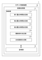
- FIG. 2 is a diagram showing the configuration of the robot control device 1.
- the robot control device 1 includes an image processing device 10.
- the robot control device 1 has a general configuration for controlling the robot 2, but is omitted for the sake of simplification of description.
- the image processing device 10 is a device for processing the captured image captured by the visual sensor 4.
- the image processing device 10 includes a control unit 11 and a storage unit 12.
- the control unit 11 is a processor such as a CPU (Central Processing Unit), and realizes various functions by executing a program stored in the storage unit 12.
- CPU Central Processing Unit
- the control unit 11 includes a first exposure time determination unit 111, a second exposure time determination unit 112, a third exposure time determination unit 113, an imaging condition determination unit 114, and a composite image generation unit 115.
- the storage unit 12 stores an OS (Operating System), a ROM (Read Only Memory) for storing application programs, a RAM (Random Access Memory), a hard disk drive for storing various other information, and an SSD (Solid State Drive). It is a device.
- the storage unit 12 stores various information such as, for example, a robot program.
- the first exposure time determination unit 111 determines the minimum value of the exposure time for photographing the subject (for example, the work W shown in FIG. 1). Specifically, the first exposure time determination unit 111 calculates the brightness in the captured image obtained by capturing the subject with the minimum value of the exposure time, and the value based on the calculated brightness is smaller than the first threshold value H1. , Change the minimum exposure time. Then, the first exposure time determination unit 111 repeats imaging of the subject, calculation of the brightness, and change of the minimum value of the exposure time until the value based on the brightness becomes equal to or higher than the first threshold value H1, and the minimum value of the exposure time is obtained. To decide.
- the first exposure time determining unit 111 sets a minimum value of the exposure time for photographing the subject in advance, and first of the brightness of the captured image obtained by capturing the subject with the minimum value of the exposure time. Calculate the histogram.
- the first exposure time determining unit 111 exposes the value having the highest luminance to approach the first threshold value H1.
- Change the minimum time For example, the first exposure time determination unit 111 changes the minimum exposure time by multiplying the minimum exposure time by a predetermined value.
- the first threshold value H1 is a value indicating that the value having the highest luminance in the first histogram is sufficiently large.
- the first exposure time determination unit 111 captures the subject, calculates the first histogram, and minimizes the exposure time until the value having the highest brightness in the first histogram becomes the first threshold value H1 or more. Repeat the changes to determine the minimum exposure time.
- the second exposure time determination unit 112 determines the maximum value of the exposure time for photographing the subject (for example, the work W shown in FIG. 1). Specifically, the second exposure time determination unit 112 calculates the brightness in the captured image obtained by capturing the subject with the maximum value of the exposure time, and the value based on the calculated brightness is larger than the second threshold value H2. , The maximum value of the exposure time is changed, and the image of the subject, the acquisition of the brightness, and the change of the maximum value of the exposure time are repeated until the value based on the brightness becomes equal to or less than the second threshold value, and the maximum value of the exposure time is determined. do.
- the second exposure time determination unit 112 sets the maximum value of the exposure time for capturing the subject, and sets the second histogram of the brightness of the captured image obtained by capturing the subject at the maximum value of the exposure time. calculate.
- the second exposure time determining unit 112 exposes the value having the smallest brightness closer to the second threshold value H2. Change the maximum time. For example, the second exposure time determination unit 112 changes the maximum value of the exposure time by multiplying the maximum value of the exposure time by a predetermined value. Further, the second threshold value H2 is a value indicating that the value having the smallest luminance in the second histogram is sufficiently small.
- the second exposure time determination unit 112 captures the subject, acquires the second histogram, and maximizes the exposure time until the value having the smallest brightness in the second histogram becomes equal to or less than the second threshold value H2. Repeat the changes to determine the maximum exposure time.
- the first exposure time determination unit 111 uses the minimum value of the exposure time of the captured image captured in advance when setting the minimum value of the exposure time in advance.
- the second exposure time determining unit uses the maximum value of the exposure time of the captured image captured in advance.
- the first exposure time determination unit 111 stores in advance the minimum value of the exposure time of the captured image captured at the time of the previous imaging. Then, when setting the minimum value of the exposure time in advance, the first exposure time determination unit 111 uses the minimum value of the exposure time of the captured image captured at the time of the previous imaging.
- the second exposure time determination unit 112 stores in advance the maximum value of the exposure time of the captured image captured at the time of the previous imaging. Then, when setting the maximum value of the exposure time in advance, the second exposure time determination unit 112 uses the maximum value of the exposure time of the captured image captured at the time of the previous imaging. As a result, the image processing apparatus 10 can speed up the measurement of the range of the exposure time.
- the first exposure time determination unit 111 uses the minimum exposure time of the captured image designated from the outside (for example, a teaching operation panel operated by the operator) when setting the minimum exposure time in advance. You may. Further, when setting the maximum value of the exposure time in advance, the second exposure time determination unit 112 may use the maximum value of the exposure time of the captured image from the outside (for example, a teaching operation panel operated by the operator). ..
- the third exposure time determination unit 113 calculates a reference histogram of the brightness of the captured image in which the subject is imaged at the reference exposure time between the minimum value of the exposure time and the maximum value of the exposure time, and stores the calculated reference histogram. Store in 12.
- the third exposure time determination unit 113 calculates a third histogram of the brightness of the captured image obtained by capturing the subject at the reference exposure time, and calculates the exposure time coefficient so that the third histogram matches the reference histogram. ..
- the imaging condition determination unit 114 determines the exposure time for imaging the subject and the number of imaging times for imaging the subject based on the exposure time range including the determined minimum value of the exposure time and the maximum value of the exposure time.
- the imaging condition determination unit 114 divides the exposure time range including the determined minimum value of the exposure time and the maximum value of the exposure time into appropriate predetermined sections, sets the divided portion as the exposure time, and determines the number of times of the division.
- the exposure time and the number of times of imaging are determined by the number of times of imaging.
- the imaging condition determination unit 114 divides the exposure time range into five, that is, determines that the number of imaging times is 5, the predetermined section includes the section A1, the section A2, the section A3, and the section A4. Then, in the imaging condition determination unit 114, the section A2 is twice as long as the section A1, the section A3 is four times as long as the section A1, and the section A4 is eight times as long as the section A1. Separate the exposure time range. That is, the lengths of the sections A1, the section A2, the section A3, and the section A4 are in a proportional relationship.
- the imaging condition determination unit 114 calculates the exposure time range based on the minimum value of the exposure time, the maximum value of the exposure time, and the exposure time coefficient.
- the imaging condition determination unit 114 considers the reference exposure time by multiplying the exposure time coefficient calculated by the third exposure time determination unit 113 by the minimum value of the exposure time and the maximum value of the exposure time. Find the minimum value of the exposure time and the maximum value of the exposure time. Then, the imaging condition determination unit 114 calculates an exposure time range including the obtained minimum value of the exposure time and the maximum value of the exposure time. As a result, the image processing apparatus 10 can calculate the exposure time range in consideration of the reference histogram and the reference exposure time.
- the captured image used to determine the exposure time is a reduced image.
- the image processing apparatus 10 can speed up the process for determining the exposure time by using the reduced image as compared with the case of using the captured image of a normal size.
- the composite image generation unit 115 synthesizes a plurality of captured images of the subject using the determined exposure time and the number of imaging times, and generates a composite image. In this way, the image processing apparatus 10 generates a composite image synthesized by HDR (High Dynamic Range).
- HDR High Dynamic Range
- the first exposure time determination unit 111 may determine the minimum value based on the value of the first percentile from the brightest one, for example, instead of the maximum value or the minimum value of the above-mentioned brightness. Further, the second exposure time determination unit 112 may determine the maximum value based on the value of the 1st percentile from the darkest one, for example, instead of the above-mentioned histogram.
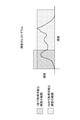
- FIG. 3 is a diagram showing the brightness that can be acquired in the HDR composite image.
- the range of brightness that can be acquired by the HDR composite image becomes wider than the range of brightness that can be acquired by one captured image. Therefore, the image processing device 1 can obtain a captured image having a high resolution.
- the composite image generation unit 115 makes it possible to specify at least one of a whiteout ratio and a blackout ratio in a plurality of captured images, and in the composite image, the pixels having the whiteout ratio are white and blackened. Tone mapping of the composite image is performed with the ratio pixels set to black.
- FIG. 4 is a diagram showing a specific example of the ratio of overexposure and the ratio of underexposure in the luminance histogram.
- the composite image generation unit 115 in the histogram of the brightness of the composite image, the pixel in the region of 10% having the lowest brightness is black, and the pixel in the region of 10% having the highest brightness is white. ..
- the composite image generation unit 115 can also store the image before generating the composite image. For example, the composite image generation unit 115 may save all of a plurality of captured images, or save an image before tone mapping. As a result, the image processing apparatus 10 can adjust the parameters related to image composition by using the stored image when the detection or inspection of the object by the composite image fails. Further, the image processing apparatus 10 can automatically try another parameter adjustment method so that the system does not stop.
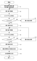
- FIG. 5 is a flowchart showing a processing flow of the image processing apparatus 10.
- the first exposure time determination unit 111 sets the minimum value of the exposure time for photographing the subject in advance
- the second exposure time determination unit 112 sets the maximum value of the exposure time for imaging the subject. Set.
- step S2 the visual sensor 4 images the subject with the minimum value of the preset exposure time.
- step S3 the first exposure time determination unit 111 calculates the first histogram of the brightness of the captured image obtained by capturing the subject with the minimum exposure time.
- step S4 the first exposure time determination unit 111 determines whether or not the value Lmax having the highest brightness in the first histogram calculated in step S3 is equal to or greater than the first threshold value H1.
- Lmax is equal to or higher than the first threshold value H1 (YES)
- the process proceeds to step S6.
- Lmax is less than the first threshold value H1 (NO)
- the process proceeds to step S5.
- step S5 the first exposure time determination unit 111 changes the minimum exposure time so that the value having the highest luminance approaches the first threshold value H1.
- step S6 the first exposure time determination unit 111 determines the minimum exposure time by repeating the processes of steps S2 to S5.
- step S7 the visual sensor 4 takes an image of the subject at the maximum value of the preset exposure time.
- step S8 the second exposure time determination unit 112 calculates a second histogram of the brightness of the captured image obtained by capturing the subject at the maximum value of the exposure time.
- step S9 the second exposure time determination unit 112 determines whether or not the value Lmin having the lowest brightness in the second histogram calculated in step S8 is equal to or less than the second threshold value H2.
- Lmin is equal to or less than the second threshold value H2 (YES)
- the process proceeds to step S11.
- the Lmin exceeds the second threshold value H2 (NO) the process proceeds to step S10.
- step S10 the second exposure time determination unit 112 changes the maximum value of the exposure time so that the value having the smallest brightness approaches the second threshold value H2.
- step S11 the second exposure time determination unit 112 determines the maximum value of the exposure time by repeating the processes of steps S7 to S10.
- step S12 the imaging condition determination unit 114 exposes the subject to be imaged based on the exposure time range including the minimum value of the exposure time determined in step S6 and the maximum value of the exposure time determined in step S11. Determine the time and the number of times the subject is imaged.
- step S13 the composite image generation unit 115 synthesizes a plurality of captured images of the subject using the exposure time and the number of imagings determined in step S12, and generates a composite image.
- the image processing apparatus 10 has a first exposure time determination unit 111 that determines the minimum value of the exposure time for imaging the subject, and an exposure time for imaging the subject. Based on the second exposure time determination unit 112 that determines the maximum value of, and the exposure time range including the determined minimum value of the exposure time and the maximum value of the exposure time, the exposure time for imaging the subject and the subject are imaged. It includes an imaging condition determination unit 114 that determines the number of imagings to be performed, and a composite image generation unit that synthesizes a plurality of captured images of a subject using the determined exposure time and the number of imagings to generate a composite image.
- the image processing device 10 can determine an appropriate exposure time range and the number of times of imaging for imaging the subject without having a photometric sensor or the like, and can obtain a composite image.
- the first exposure time determination unit 111 calculates the brightness in the captured image obtained by capturing the subject with the minimum value of the exposure time, and when the value based on the calculated brightness is smaller than the first threshold value H1, the exposure time. Change the minimum value of. Then, the first exposure time determination unit 111 repeats imaging of the subject, calculation of the brightness, and change of the minimum value of the exposure time until the value based on the brightness becomes equal to or higher than the first threshold value H1, and the minimum value of the exposure time is obtained. To decide. Thereby, the image processing apparatus 10 can appropriately determine the minimum value of the exposure time.
- the second exposure time determination unit 112 calculates the brightness in the captured image obtained by capturing the subject with the maximum value of the exposure time, and when the value based on the calculated brightness is larger than the second threshold value H2, the exposure time. Change the maximum value of. Then, the second exposure time determination unit 112 repeats imaging of the subject, acquisition of the brightness, and change of the maximum value of the exposure time until the value based on the brightness becomes equal to or less than the second threshold value, and sets the maximum value of the exposure time. decide. Thereby, the image processing apparatus 10 can appropriately determine the maximum value of the exposure time.
- the captured image used to determine the exposure time is a reduced image.
- the image processing apparatus 10 can speed up the process for determining the exposure time by using the reduced image as compared with the case of using the captured image of a normal size.
- the first exposure time determination unit 111 uses the minimum exposure time of the captured image captured in advance when setting the minimum exposure time in advance.
- the second exposure time determination unit 112 uses the maximum value of the exposure time of the captured image captured in advance when setting the maximum value of the exposure time in advance. As a result, the image processing apparatus 10 can speed up the measurement of the range of the exposure time.
- the first exposure time determination unit 111 may use the minimum exposure time of the captured image designated from the outside when setting the minimum exposure time in advance.
- the second exposure time determination unit 112 may use the maximum value of the exposure time of the captured image from the outside when setting the maximum value of the exposure time in advance. As a result, the image processing apparatus 10 can speed up the measurement of the range of the exposure time.
- the third exposure time determination unit 113 calculates a reference histogram of the brightness of the captured image obtained by capturing the subject at the reference exposure time between the minimum value of the exposure time and the maximum value of the exposure time, and stores the reference histogram. Store in 12. Next, the third exposure time determination unit 113 calculates a third histogram of the brightness of the captured image in which the subject is imaged at the reference exposure time, and the exposure time so that the third histogram matches the reference histogram. Calculate the histogram.
- the imaging condition determination unit 114 calculates the exposure time range based on the minimum value of the exposure time, the maximum value of the exposure time, and the exposure time coefficient. As a result, the image processing apparatus 10 can calculate the exposure time range in consideration of the reference histogram and the reference exposure time.
- the composite image generation unit 115 makes it possible to specify at least one of a whiteout ratio and a blackout ratio in a plurality of captured images, and in the composite image, the pixels having the whiteout ratio are white and blackened. Tone mapping of the composite image is performed with the ratio pixels set to black. As a result, the image processing apparatus 10 can appropriately obtain a composite image having a high resolution.
- the composite image generation unit 115 enables the composite image generation by a different composite method by recording the information of the original image before the composite image is generated.
- the image processing apparatus 10 can adjust the parameters related to image composition by using the stored image when the detection or inspection of the object by the composite image fails.
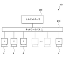
- FIG. 6 is a diagram schematically showing an example of an image processing system 201 to which a plurality of visual sensors 4 according to an embodiment of the present invention are connected.
- N visual sensors 4 are connected to the cell controller 200 via the network bus 210.
- the cell controller 200 has the same function as the image processing device 10 described above, and acquires captured images acquired from each of the N visual sensors 4.
- the cell controller 200 may have, for example, a machine learning device (not shown).
- the machine learning device acquires a collection of learning data stored in the cell controller 200 and performs supervised learning.
- the learning process can be sequentially processed online.
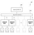
- FIG. 7 is a diagram schematically showing an example of an image processing system 301 to which a plurality of image processing devices 10 according to an embodiment of the present invention are connected.
- m image processing devices 10 are connected to the cell controller 200 via the network bus 210.
- One or a plurality of visual sensors 4 are connected to each of the image processing devices 10.
- the image processing system 301 as a whole includes a total of n visual sensors 4.
- the cell controller 200 may have, for example, a machine learning device (not shown).
- the cell controller 200 may store a collection of learning data sent from a plurality of image processing devices 10 as a learning data set, and perform machine learning to construct a learning model.
- the learning model becomes available in each image processing device 10.
- the image processing apparatus 10 controls the exposure time in the above-described embodiment, it may control the optical parameters other than the exposure time.
- the image processing apparatus 10 may control optical parameters such as the gain of the image sensor and the aperture of the lens instead of the exposure time.
- the image processing apparatus 10 has a first exposure time determining unit 111 that determines the minimum value of the optical parameter for photographing the subject, and a second exposure time that determines the maximum value of the optical parameter for imaging the subject.
- An imaging condition determination unit that determines the optical parameters for imaging the subject and the number of imaging times for imaging the subject based on the determination unit 112 and the optical parameter range including the determined minimum value of the optical parameter and the maximum value of the optical parameter.
- the 114 is provided with a composite image generation unit that synthesizes a plurality of captured images of a subject using a determined optical parameter and the number of imaging times to generate a composite image.
- the image processing device 10 can determine an appropriate range of optical parameters and the number of times of imaging for imaging a subject without having a photometric sensor or the like, and can obtain a composite image.
- the robot control device 1 described above can be realized by hardware, software, or a combination thereof. Further, the control method performed by the robot control device 1 described above can also be realized by hardware, software, or a combination thereof.
- what is realized by software means that it is realized by a computer reading and executing a program.
- Non-transitory computer-readable media include various types of tangible storage media.
- Examples of non-temporary computer-readable media include magnetic recording media (eg, hard disk drives), magneto-optical recording media (eg, magneto-optical disks), CD-ROMs (Read Only Memory), CD-Rs, CD-Rs / W, including semiconductor memory (for example, mask ROM, PROM (Programmable ROM), EPROM (Erasable PROM), flash ROM, RAM (random access memory)).
- Robot control device 2 Robot 3 Arm 4 Visual sensor 10 Image processing device 11 Control unit 12 Storage unit 100 Robot system 111 1st exposure time determination unit 112 2nd exposure time determination unit 113 3rd exposure time determination unit 114 Imaging condition determination unit 115 Composite image generator
Landscapes
- Engineering & Computer Science (AREA)
- Multimedia (AREA)
- Signal Processing (AREA)
- Physics & Mathematics (AREA)
- General Physics & Mathematics (AREA)
- Theoretical Computer Science (AREA)
- Studio Devices (AREA)
- Manipulator (AREA)
- Exposure Control For Cameras (AREA)
Abstract
Description
図1は、ロボットシステム100の構成を示す図である。図1に示すように、ロボットシステム100は、ロボット制御装置1と、ロボット2と、アーム3と、視覚センサ4と、を備える。
具体的には、第1露光時間決定部111は、露光時間の最小値で被写体を撮像した撮像画像において輝度を算出し、算出された輝度に基づく値が、第1の閾値H1よりも小さい場合、露光時間の最小値を変更する。そして、第1露光時間決定部111は、輝度に基づく値が、第1の閾値H1以上になるまで、被写体の撮像、輝度の算出及び露光時間の最小値の変更を繰り返し、露光時間の最小値を決定する。
具体的には、第2露光時間決定部112は、露光時間の最大値で被写体を撮像した撮像画像において輝度を算出し、算出された輝度に基づく値が、第2の閾値H2よりも大きい場合、露光時間の最大値を変更し、輝度に基づく値が、第2の閾値以下になるまで、被写体の撮像、輝度の取得及び露光時間の最大値の変更を繰り返し、露光時間の最大値を決定する。
そして、撮像条件決定部114は、区間A2が区間A1の2倍の長さとなり、区間A3が区間A1の4倍の長さとなり、区間A4が区間A1の8倍の長さとなるように、露光時間範囲を区切る。すなわち、区間A1、区間A2、区間A3及び区間A4の長さは比例関係となる。
ステップS1において、第1露光時間決定部111は、被写体を撮像するための露光時間の最小値を予め設定し、第2露光時間決定部112は、被写体を撮像するための露光時間の最大値を設定する。
ステップS3において、第1露光時間決定部111は、露光時間の最小値で被写体を撮像した撮像画像の輝度の第1のヒストグラムを算出する。
ステップS8において、第2露光時間決定部112は、露光時間の最大値で被写体を撮像した撮像画像の輝度の第2のヒストグラムを算出する。
2 ロボット
3 アーム
4 視覚センサ
10 画像処理装置
11 制御部
12 記憶部
100 ロボットシステム
111 第1露光時間決定部
112 第2露光時間決定部
113 第3露光時間決定部
114 撮像条件決定部
115 合成画像生成部
Claims (11)
- 被写体を撮像した撮像画像を処理する画像処理装置であって、
前記被写体を撮像するための露光時間の最小値を決定する第1露光時間決定部と、
前記被写体を撮像するための前記露光時間の最大値を決定する第2露光時間決定部と、
決定された前記露光時間の最小値及び前記露光時間の最大値を含む露光時間範囲に基づいて、前記被写体を撮像するための前記露光時間及び前記被写体を撮像する撮像回数を決定する撮像条件決定部と、
決定された前記露光時間及び前記撮像回数を用いて前記被写体を撮像した複数の撮像画像を合成し、合成画像を生成する合成画像生成部と、
を備える画像処理装置。 - 前記第1露光時間決定部は、
前記被写体を撮像するための前記露光時間の最小値を予め設定し、
前記露光時間の最小値で前記被写体を撮像した前記撮像画像において輝度を算出し、算出された前記輝度に基づく値が、第1の閾値よりも小さい場合、前記露光時間の最小値を変更し、
前記輝度に基づく値が、前記第1の閾値以上になるまで、前記被写体の撮像、前記輝度の算出及び前記露光時間の最小値の変更を繰り返し、前記露光時間の最小値を決定する、
請求項1に記載の画像処理装置。 - 前記第2露光時間決定部は、
前記被写体を撮像するための前記露光時間の最大値を設定し、
前記露光時間の最大値で前記被写体を撮像した前記撮像画像において輝度を算出し、算出された前記輝度に基づく値が、第2の閾値よりも大きい場合、前記露光時間の最大値を変更し、
前記輝度に基づく値が、前記第2の閾値以下になるまで、前記被写体の撮像、前記輝度の取得及び前記露光時間の最大値の変更を繰り返し、前記露光時間の最大値を決定する、
請求項1又は2に記載の画像処理装置。 - 前記露光時間を決定するために用いられる前記撮像画像は、縮小画像である、請求項1から3のいずれか一項に記載の画像処理装置。
- 前記第1露光時間決定部は、前記露光時間の最小値を予め設定する際に、事前に撮像された前記撮像画像の前記露光時間の最小値を用い、
前記第2露光時間決定部は、前記露光時間の最大値を予め設定する際に、事前に撮像された前記撮像画像の前記露光時間の最大値を用いる、請求項1から4のいずれか一項に記載の画像処理装置。 - 前記第1露光時間決定部は、前記露光時間の最小値を予め設定する際に、外部から指定された前記撮像画像の前記露光時間の最小値を用い、
前記第2露光時間決定部は、前記露光時間の最大値を予め設定する際に、外部から前記撮像画像の前記露光時間の最大値を用いる、請求項1から4のいずれか一項に記載の画像処理装置。 - 前記露光時間の最小値と前記露光時間の最大値との間の基準露光時間で前記被写体を撮像した前記撮像画像の輝度の基準ヒストグラムを算出し、前記基準ヒストグラムを記憶部に記憶し、
前記基準露光時間で前記被写体を撮像した前記撮像画像の輝度の第3のヒストグラムを算出し、前記第3のヒストグラムが前記基準ヒストグラムと一致するように露光時間係数を算出する第3露光時間決定部を更に備え、
前記撮像条件決定部は、
前記前記露光時間の最小値、前記露光時間の最大値及び前記露光時間係数に基づいて、前記露光時間範囲を算出する、
請求項1から5のいずれか一項に記載の画像処理装置。 - 前記合成画像生成部は、
前記複数の撮像画像において白飛びさせる割合と黒潰れさせる割合との少なくとも一方を指定可能とし、
前記合成画像において、白飛びさせる割合の画素を白色とし、かつ黒潰れさせる割合の画素を黒色とした状態で、前記合成画像のトーンマッピングを行う、
請求項1から6のいずれか一項に記載の画像処理装置。 - 前記合成画像生成部は、
前記合成画像を生成する前の元の画像の情報を記録することによってで、異なる合成方法による合成画像生成を可能にする、請求項1から7のいずれか一項に記載の画像処理装置。 - 被写体を撮像した撮像画像を処理する画像処理装置を有するロボット制御装置であって、
前記被写体を撮像するための露光時間の最小値を決定する第1露光時間決定部と、
前記被写体を撮像するための前記露光時間の最大値を決定する第2露光時間決定部と、
決定された前記露光時間の最小値及び前記露光時間の最大値を含む露光時間範囲に基づいて、前記被写体を撮像するための前記露光時間及び前記被写体を撮像する撮像回数を決定する撮像条件決定部と、
決定された前記露光時間及び前記撮像回数を用いて前記被写体を撮像した複数の撮像画像を合成し、合成画像を生成する合成画像生成部と、
を備えるロボット制御装置。 - 被写体を撮像した撮像画像を処理する画像処理装置であって、
前記被写体を撮像するための光学パラメータの最小値を決定する第1露光時間決定部と、
前記被写体を撮像するための前記光学パラメータの最大値を決定する第2露光時間決定部と、
決定された前記光学パラメータの最小値及び前記光学パラメータの最大値を含む光学パラメータ間範囲に基づいて、前記被写体を撮像するための前記光学パラメータ及び前記被写体を撮像する撮像回数を決定する撮像条件決定部と、
決定された前記光学パラメータ及び前記撮像回数を用いて前記被写体を撮像した複数の撮像画像を合成し、合成画像を生成する合成画像生成部と、
を備える画像処理装置。
Priority Applications (4)
| Application Number | Priority Date | Filing Date | Title |
|---|---|---|---|
| CN202180056650.6A CN116034002B (zh) | 2020-08-11 | 2021-08-04 | 图像处理装置和机器人控制装置 |
| DE112021004256.4T DE112021004256T5 (de) | 2020-08-11 | 2021-08-04 | Bildverarbeitungsvorrichtung und Roboter-Steuervorrichtung |
| US18/040,413 US20240257308A1 (en) | 2020-08-11 | 2021-08-04 | Image processing device and robot control device |
| JP2022542820A JP7568725B2 (ja) | 2020-08-11 | 2021-08-04 | 画像処理装置及びロボット制御装置 |
Applications Claiming Priority (2)
| Application Number | Priority Date | Filing Date | Title |
|---|---|---|---|
| JP2020135607 | 2020-08-11 | ||
| JP2020-135607 | 2020-08-11 |
Publications (1)
| Publication Number | Publication Date |
|---|---|
| WO2022034840A1 true WO2022034840A1 (ja) | 2022-02-17 |
Family
ID=80247865
Family Applications (1)
| Application Number | Title | Priority Date | Filing Date |
|---|---|---|---|
| PCT/JP2021/028911 Ceased WO2022034840A1 (ja) | 2020-08-11 | 2021-08-04 | 画像処理装置及びロボット制御装置 |
Country Status (5)
| Country | Link |
|---|---|
| US (1) | US20240257308A1 (ja) |
| JP (1) | JP7568725B2 (ja) |
| CN (1) | CN116034002B (ja) |
| DE (1) | DE112021004256T5 (ja) |
| WO (1) | WO2022034840A1 (ja) |
Families Citing this family (1)
| Publication number | Priority date | Publication date | Assignee | Title |
|---|---|---|---|---|
| JP2025004459A (ja) * | 2023-06-26 | 2025-01-15 | キヤノン株式会社 | 光電変換装置、画像処理装置、移動体、処理方法、及びコンピュータプログラム |
Citations (1)
| Publication number | Priority date | Publication date | Assignee | Title |
|---|---|---|---|---|
| JP2012222540A (ja) * | 2011-04-07 | 2012-11-12 | Olympus Corp | 撮像装置 |
Family Cites Families (12)
| Publication number | Priority date | Publication date | Assignee | Title |
|---|---|---|---|---|
| JP4695508B2 (ja) | 2005-12-28 | 2011-06-08 | 三星電子株式会社 | 撮像装置および撮影方法 |
| JP5397068B2 (ja) * | 2009-06-03 | 2014-01-22 | ソニー株式会社 | 撮像装置、撮像制御方法、露出制御装置および露出制御方法 |
| JP2011024088A (ja) * | 2009-07-17 | 2011-02-03 | Sony Corp | 撮像装置および撮像制御方法 |
| JP5003840B1 (ja) * | 2011-10-31 | 2012-08-15 | オムロン株式会社 | 画像処理装置および画像処理プログラム |
| JP2013118562A (ja) * | 2011-12-05 | 2013-06-13 | Nikon Corp | 撮像装置 |
| JP6025400B2 (ja) | 2012-05-29 | 2016-11-16 | キヤノン株式会社 | ワーク位置検出装置、及びワーク位置検出方法 |
| JP6120500B2 (ja) * | 2012-07-20 | 2017-04-26 | キヤノン株式会社 | 撮像装置およびその制御方法 |
| US9307207B2 (en) * | 2013-01-07 | 2016-04-05 | GM Global Technology Operations LLC | Glaring reduction for dynamic rearview mirror |
| US10616511B2 (en) * | 2017-06-08 | 2020-04-07 | Intel Corporation | Method and system of camera control and image processing with a multi-frame-based window for image data statistics |
| JP6810087B2 (ja) * | 2018-03-29 | 2021-01-06 | ファナック株式会社 | 機械学習装置、機械学習装置を用いたロボット制御装置及びロボットビジョンシステム、並びに機械学習方法 |
| DE102018124015B4 (de) * | 2018-09-28 | 2021-07-29 | Basler Ag | System und Verfahren zur Erfassung von Bildern |
| CN110445989B (zh) * | 2019-08-05 | 2021-03-23 | Oppo广东移动通信有限公司 | 图像处理方法、装置、存储介质及电子设备 |
-
2021
- 2021-08-04 JP JP2022542820A patent/JP7568725B2/ja active Active
- 2021-08-04 CN CN202180056650.6A patent/CN116034002B/zh active Active
- 2021-08-04 US US18/040,413 patent/US20240257308A1/en active Pending
- 2021-08-04 WO PCT/JP2021/028911 patent/WO2022034840A1/ja not_active Ceased
- 2021-08-04 DE DE112021004256.4T patent/DE112021004256T5/de active Pending
Patent Citations (1)
| Publication number | Priority date | Publication date | Assignee | Title |
|---|---|---|---|---|
| JP2012222540A (ja) * | 2011-04-07 | 2012-11-12 | Olympus Corp | 撮像装置 |
Also Published As
| Publication number | Publication date |
|---|---|
| CN116034002B (zh) | 2025-09-12 |
| CN116034002A (zh) | 2023-04-28 |
| JPWO2022034840A1 (ja) | 2022-02-17 |
| DE112021004256T5 (de) | 2023-07-06 |
| US20240257308A1 (en) | 2024-08-01 |
| JP7568725B2 (ja) | 2024-10-16 |
Similar Documents
| Publication | Publication Date | Title |
|---|---|---|
| JP5719418B2 (ja) | ハイダイナミックレンジ画像の露光時間制御方法 | |
| JP4240023B2 (ja) | 撮像装置、撮像方法および撮像プログラム、ならびに、画像処理装置、画像処理方法および画像処理プログラム | |
| JP2009212853A (ja) | ホワイトバランス制御装置およびその制御方法並びに撮像装置 | |
| JP2001311980A (ja) | 露出制御装置 | |
| CN100546341C (zh) | 成像设备 | |
| JP2019047169A (ja) | ハイダイナミックレンジ画像を作成する装置、方法、及びプログラム | |
| US10067327B2 (en) | Image acquisition apparatus | |
| WO2020148868A1 (ja) | 情報処理装置、情報処理方法及び情報処理プログラム | |
| JP2015144475A (ja) | 撮像装置、撮像装置の制御方法、プログラム及び記憶媒体 | |
| JP2022057352A (ja) | 情報処理装置、情報処理方法、及び、プログラム | |
| WO2022034840A1 (ja) | 画像処理装置及びロボット制御装置 | |
| JP2017229025A (ja) | 画像処理装置、画像処理方法、及びプログラム | |
| JP5713643B2 (ja) | 撮像装置、撮像装置の制御方法、プログラム及び記憶媒体 | |
| WO2022153935A1 (ja) | 画像生成装置、ロボット制御装置及びコンピュータプログラム | |
| CN116210026A (zh) | 拍摄条件调整装置以及拍摄条件调整方法 | |
| JP4274316B2 (ja) | 撮像システム | |
| CN103905722A (zh) | 图像处理装置以及图像处理方法 | |
| JP5587045B2 (ja) | 撮像装置及びその制御方法 | |
| JP6554009B2 (ja) | 画像処理装置、その制御方法、プログラム及び記録媒体 | |
| US11711619B2 (en) | Controlling exposure based on inverse gamma characteristic | |
| JP5595159B2 (ja) | 撮像装置及びその制御方法 | |
| EP4243402A1 (en) | Information processing device, image capturing device, program, storage medium, and method | |
| CN119922422A (zh) | 图像处理装置以及拍摄装置 | |
| JP2018133686A (ja) | 撮像装置及び画像処理装置とその制御方法並びにプログラム | |
| JP5587084B2 (ja) | 撮像装置及びその制御方法 |
Legal Events
| Date | Code | Title | Description |
|---|---|---|---|
| 121 | Ep: the epo has been informed by wipo that ep was designated in this application |
Ref document number: 21855919 Country of ref document: EP Kind code of ref document: A1 |
|
| ENP | Entry into the national phase |
Ref document number: 2022542820 Country of ref document: JP Kind code of ref document: A |
|
| WWE | Wipo information: entry into national phase |
Ref document number: 18040413 Country of ref document: US |
|
| 122 | Ep: pct application non-entry in european phase |
Ref document number: 21855919 Country of ref document: EP Kind code of ref document: A1 |
|
| WWG | Wipo information: grant in national office |
Ref document number: 202180056650.6 Country of ref document: CN |