WO2022034707A1 - 車両制御装置 - Google Patents
車両制御装置 Download PDFInfo
- Publication number
- WO2022034707A1 WO2022034707A1 PCT/JP2021/008636 JP2021008636W WO2022034707A1 WO 2022034707 A1 WO2022034707 A1 WO 2022034707A1 JP 2021008636 W JP2021008636 W JP 2021008636W WO 2022034707 A1 WO2022034707 A1 WO 2022034707A1
- Authority
- WO
- WIPO (PCT)
- Prior art keywords
- vehicle
- driver
- control
- follow
- determined
- Prior art date
- Legal status (The legal status is an assumption and is not a legal conclusion. Google has not performed a legal analysis and makes no representation as to the accuracy of the status listed.)
- Ceased
Links
Images



Classifications
-
- B—PERFORMING OPERATIONS; TRANSPORTING
- B60—VEHICLES IN GENERAL
- B60W—CONJOINT CONTROL OF VEHICLE SUB-UNITS OF DIFFERENT TYPE OR DIFFERENT FUNCTION; CONTROL SYSTEMS SPECIALLY ADAPTED FOR HYBRID VEHICLES; ROAD VEHICLE DRIVE CONTROL SYSTEMS FOR PURPOSES NOT RELATED TO THE CONTROL OF A PARTICULAR SUB-UNIT
- B60W30/00—Purposes of road vehicle drive control systems not related to the control of a particular sub-unit, e.g. of systems using conjoint control of vehicle sub-units
- B60W30/14—Adaptive cruise control
- B60W30/16—Control of distance between vehicles, e.g. keeping a distance to preceding vehicle
-
- B—PERFORMING OPERATIONS; TRANSPORTING
- B60—VEHICLES IN GENERAL
- B60W—CONJOINT CONTROL OF VEHICLE SUB-UNITS OF DIFFERENT TYPE OR DIFFERENT FUNCTION; CONTROL SYSTEMS SPECIALLY ADAPTED FOR HYBRID VEHICLES; ROAD VEHICLE DRIVE CONTROL SYSTEMS FOR PURPOSES NOT RELATED TO THE CONTROL OF A PARTICULAR SUB-UNIT
- B60W40/00—Estimation or calculation of non-directly measurable driving parameters for road vehicle drive control systems not related to the control of a particular sub unit, e.g. by using mathematical models
- B60W40/08—Estimation or calculation of non-directly measurable driving parameters for road vehicle drive control systems not related to the control of a particular sub unit, e.g. by using mathematical models related to drivers or passengers
-
- F—MECHANICAL ENGINEERING; LIGHTING; HEATING; WEAPONS; BLASTING
- F02—COMBUSTION ENGINES; HOT-GAS OR COMBUSTION-PRODUCT ENGINE PLANTS
- F02D—CONTROLLING COMBUSTION ENGINES
- F02D29/00—Controlling engines, such controlling being peculiar to the devices driven thereby, the devices being other than parts or accessories essential to engine operation, e.g. controlling of engines by signals external thereto
- F02D29/02—Controlling engines, such controlling being peculiar to the devices driven thereby, the devices being other than parts or accessories essential to engine operation, e.g. controlling of engines by signals external thereto peculiar to engines driving vehicles; peculiar to engines driving variable pitch propellers
-
- G—PHYSICS
- G08—SIGNALLING
- G08G—TRAFFIC CONTROL SYSTEMS
- G08G1/00—Traffic control systems for road vehicles
- G08G1/16—Anti-collision systems
Definitions
- the present invention relates to a vehicle control device that is mounted on a saddle-mounted vehicle such as a motorcycle and that follows the vehicle while maintaining a safe distance and relative speed from the preceding vehicle.
- ACC Adaptive Cruise Control
- Patent Document 1 discloses that the ACC control is stopped while the vehicle is running.
- ACC control is stopped when the front wheel brake is operated by the brake lever.
- the brake pedal may be operated. In such a case, if the operating time is less than the predetermined value, A technique for continuing ACC control and stopping ACC control if the operating time is equal to or longer than a predetermined value is disclosed.
- Patent Document 1 since it is determined that the ACC control is stopped due to the driver's brake operation, the determination is not made when the brake operation is not performed. Therefore, if the driving force is changed by the ACC control unintentionally by the driver, the posture of the vehicle may be disturbed.
- Patent Document 1 it is determined to stop the ACC control, and if it is desired to start the ACC control again after stopping the ACC control, it is necessary to re-operate to start the ACC control, which is convenient for the function. There is also a concern that it will hurt.
- the present invention has been made in view of the above circumstances, and an object of the present invention is a vehicle control device capable of effectively suppressing disturbance of vehicle posture due to ACC control in a saddle-type vehicle such as a motorcycle. Is to provide.
- the vehicle control device controls the follow-up running in the vehicle control device of the saddle-type vehicle that performs the follow-up run control to make the own vehicle follow the preceding vehicle. Based on the vehicle speed information of the own vehicle, it is determined whether the driver of the own vehicle can respond to the change in the driving force due to the follow-up travel control, and if it is determined that the driver can respond, the follow-up travel control is continued. It is characterized by.
- the vehicle control device of the present invention is driven by ACC control based on the vehicle speed information of the own vehicle in order to prevent the change in driving force in a state where the driver cannot respond to the change in driving force by ACC control, for example, in a low speed range. It is determined whether the force can be changed, and if it is possible, the follow-up driving control is continued. Further, as a result of the determination, if it is determined that the response is not possible and there is a possibility that the change in the driving force due to the ACC control may be dangerous, the change in the driving force due to the ACC control is suppressed or the ACC control is interrupted.
- the vehicle control device of the present invention since the ACC control is continued only when the driver can respond to the change in the driving force due to the ACC control, it is possible to prevent the vehicle posture from being disturbed and the driver is in a dangerous state. You can prevent it from becoming.
- ACC controlled vehicle system configuration block diagram The functional block diagram of the vehicle control device 100 in 1st Embodiment.
- the flowchart of the vehicle control device 100 in 1st Embodiment. Judgment condition of determination S206 in the first embodiment.
- FIG. 1 is a diagram showing a system configuration of a vehicle provided with a vehicle control device according to the first embodiment of the present invention.
- the vehicle control device 100 of this embodiment is mounted on a saddle-mounted vehicle such as a motorcycle (hereinafter referred to as vehicle 1 or own vehicle 1), and leads while maintaining a safe distance and relative speed from the preceding vehicle. It has a follow-up running function (ACC function) that follows the vehicle.
- ACC function follow-up running function
- the vehicle control device 100 is connected to the stereo camera 200, and the distance between the vehicle and the vehicle, the road curvature, and the vehicle bank angle measured by the stereo camera 200 are transmitted to the vehicle control device 100 by communication. Further, the vehicle control device 100 is connected to a wheel speed sensor 300 attached to the wheel, the rotation speed of the tire 900 is measured by the wheel speed sensor 300, and the speed (vehicle speed) of the own vehicle converted from the measured rotation speed is calculated. , Is transmitted to the vehicle control device 100. Further, the vehicle control device 100 is connected to the ACC control switch 700, and the switch operation information of the driver is transmitted to the vehicle control device 100 to start the driver's ACC control, release the ACC control, and set the ACC driving. Judge the speed. With this configuration, the vehicle control device 100 calculates the control amount by obtaining the inter-vehicle distance, the own vehicle speed, and the set speed during ACC travel.
- the vehicle control device 100 calculates the control amount of the brake 410 and the control amount of the engine 510 based on the calculated control amount, and determines the notification method to the driver.
- the calculated control amount by the brake 410 is transmitted by communication to the brake control unit 400 connected to the vehicle control device 100, and the brake control unit 400 operates the brake 410, which is an actuator, and uses the frictional force against the tire 900. Controls the deceleration of vehicle 1.
- control amount in the engine 510 is transmitted by communication to the engine control unit 500 connected to the vehicle control device 100, and the engine control unit 500 operates the engine 510.
- the acceleration force generated by the engine 510 is boosted through the clutch 520, the transmission 530, and the final gear 540, and is transmitted to the tire 900 to control the acceleration of the vehicle 1.
- the notification method to the driver determined by the vehicle control device 100 is transmitted by communication to the meter control unit 600 connected to the vehicle control device 100, thereby warning the meter control unit 600 using the buzzer 620. Or, the control status is notified using the display device 610.
- the vehicle control device 100 is connected to the navigation device 800, and the navigation device 800 acquires the road curvature in front of the vehicle from map information and the like and transmits it to the vehicle control device 100.
- the configuration of the vehicle 1 is not limited to the above-mentioned example.
- the surroundings of the own vehicle may be monitored by using an external recognition sensor such as a millimeter wave radar, a monocular camera, a sonar, or a laser radar, and the distance between the vehicle and the relative speed may be measured. good.
- the vehicle speed may be measured by a method other than the method using the wheel speed sensor 300.
- it may be an electric vehicle, a hybrid vehicle, a hydrogen vehicle, or the like other than the vehicle using the engine 510.
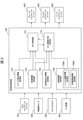
- FIG. 2 is a functional block diagram relating to the ACC function of the vehicle control device according to the first embodiment of the present invention.
- the vehicle control device 100 is configured as a microcomputer (also referred to as a microcomputer) having a CPU, ROM, RAM, etc. inside, and the CPU executes various programs stored in the ROM, and the CPU is executed. The information generated by this is temporarily stored in the RAM.
- a microcomputer also referred to as a microcomputer
- the vehicle control device 100 of the present embodiment basically includes the own vehicle traveling information acquisition unit 102, the vehicle speed information acquisition unit 103, the switch operation information acquisition unit 107, and the posture as functional blocks for realizing ACC control. It includes an information acquisition unit 109, an ACC control unit 101, and an ACC continuation possibility determination unit 110.
- the own vehicle driving information acquisition unit 102 acquires the own vehicle driving information such as the relative speed with the vehicle in front and the inter-vehicle distance information, which is the target at the time of ACC control, from the stereo camera 200. Further, the own vehicle traveling information acquisition unit 102 may acquire the road curvature in front of the vehicle as the own vehicle traveling information from the navigation device 800.
- the vehicle speed information acquisition unit 103 acquires the vehicle speed information of the own vehicle 1 obtained by measuring the rotation speed of the tire 900 from the wheel speed sensor 300.
- the switch operation information acquisition unit 107 acquires switch operation information such as the driver's ACC control start, ACC control release, and ACC running set speed from the ACC control switch 700.
- the ACC control unit 101 follows the vehicle in front, which is the target during ACC control, based on the information obtained by the own vehicle travel information acquisition unit 102, the vehicle speed information acquisition unit 103, and the switch operation information acquisition unit 107. In addition, the control amount (braking instruction) in the brake 410 and the control amount (drive instruction) in the engine 510 are calculated, and the notification method to the driver is determined. The ACC control unit 101 transmits the calculated control amount (braking instruction) of the brake 410 to the brake control unit 400 by communication, and transmits the calculated control amount (drive instruction) of the engine 510 to the engine control unit 500 by communication. Then, the deceleration and acceleration (that is, driving force) of the vehicle 1 at the time of ACC control are controlled. Further, the ACC control unit 101 communicates the determined notification method to the driver to the meter control unit 600.
- the posture information acquisition unit 109 acquires the posture information (driving posture information) of the driver boarding the vehicle (saddle-type vehicle) 1. Further, the posture information acquisition unit 109 includes a steering wheel contact information acquisition unit 109a and a scaffolding contact information acquisition unit 109b.
- the steering wheel contact information acquisition unit 109a acquires steering wheel contact information including information on whether or not the steering wheel and the driver are in contact with each other in the driving posture.
- the scaffolding contact information acquisition unit 109b acquires scaffolding contact information including information on whether or not the scaffolding and the driver are in contact with each other in the driving posture.
- the posture information acquisition unit 109 including the handle contact information acquisition unit 109a and the scaffolding contact information acquisition unit 109b will be described in detail later.
- the ACC continuation possibility determination unit 110 continues the follow-up travel by ACC control based on the information obtained by the ACC control unit 101, the own vehicle travel information acquisition unit 102, the vehicle speed information acquisition unit 103, and the attitude information acquisition unit 109. Whether or not it is possible, that is, the continuation or interruption (stop) of the follow-up running by the ACC control is determined. Specifically, the ACC continuation possibility determination unit 110 is driven by the driver (driving posture) boarding the vehicle (saddle-type vehicle) 1 based on the information obtained by the attitude information acquisition unit 109 or the like by ACC control.
- the ACC continuation possibility determination unit 110 generates a control instruction according to the determination result and transmits it to the ACC control unit 101.
- FIG. 3 is a flow chart when the driver presses the ACC control switch 700 while the vehicle is running and starts the ACC running.
- control drive instruction is received from the ACC control unit 101 while the ACC is running.
- the vehicle speed information of the own vehicle 1 obtained by measuring the rotation speed of the tire 900 is acquired via the vehicle speed information acquisition unit 103.
- the continuation determination of AAC control is made depending on whether the vehicle speed of the own vehicle 1 is a predetermined value or more at a normal speed or a high speed and the vehicle speed of the own vehicle 1 is a low speed less than a predetermined value.
- the standard is changed (in this example, it is not judged in the case of normal speed or high speed).
- the own vehicle running information such as the relative speed with the vehicle in front and the inter-vehicle distance information, which is the target at the time of ACC control measured by the stereo camera 200, is acquired via the own vehicle running information acquisition unit 102, and the vehicle concerned.
- the attitude information of the driver boarding the vehicle 1 is acquired via the attitude information acquisition unit 109.
- the driver (driving posture) of the own vehicle 1 is driven by ACC control based on the own vehicle running information such as the relative speed with the vehicle in front and the inter-vehicle distance information acquired in S205 and the driver's attitude information. It is determined whether it is possible to respond to changes in force (explained later), and if it is determined that it is possible, it shifts to S204 and it is not possible to respond, and if it is determined that there is a danger if ACC control is continued, it is determined. Move to S207.
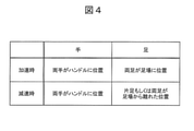
- the determination is made based on the determination condition of FIG. 4 from the attitude information of the driver acquired through the attitude information acquisition unit 109 (handle contact information acquisition unit 109a, scaffold contact information acquisition unit 109b).
- both hands are located on the steering wheel and both feet are located on the scaffolding (for example, foot pedal). If it is (in contact), it is determined that the driver of the own vehicle 1 can respond to the change in the driving force due to the ACC control. At this time, the steering wheel is disturbed because the driving force does not change due to ACC control during one-handed operation, such as when the driver holds the steering wheel with one hand and operates the switches with the other hand. It is possible to prevent the driver's posture from being disturbed.
- both hands are located on the steering wheel and one foot or both feet are separated from the scaffolding (scaffolding).
- the driver of the own vehicle 1 can respond to the change in the driving force due to the ACC control.
- the posture of the driver can be kept unchanged as in the case of acceleration.
- the position of the foot by allowing deceleration only when at least one foot is away from the scaffolding, even if deceleration from the low speed range occurs and it becomes difficult to balance the vehicle, the foot is immediately put on the ground. Can balance the vehicle.
- FIG. 5 is a flow diagram for determining whether the posture of the driver can respond to changes in the driving force due to ACC control using the determination conditions of FIG.
- the process proceeds to S403, and both hands of the driver are not located on the steering wheel, that is, If it is determined that one hand or both hands are separated from the steering wheel, the process proceeds to S407.
- the determination method at this time includes the following methods, and it is desirable to make a determination based on the one already installed in the vehicle.
- both hands of the driver are located on the handle. It can be determined that the handle and both hands of the driver are in contact with each other. That is, in this case, as the handle contact detecting means for detecting the contact between the handle and the driver's hand, an acceleration sensor (G sensor) equipped with a stereo camera for detecting the front-back, left-right, or up-down movement of the vehicle is used.
- the handle contact information acquisition unit 109a of the attitude information acquisition unit 109 acquires the amount of movement of the moving vehicle in each direction detected by the acceleration sensor which is the handle contact detection means.
- the ACC continuation possibility determination unit 110 moves the moving vehicle in each direction acquired via the steering wheel contact information acquisition unit 109a of the attitude information acquisition unit 109 (corresponding to the contact information between the steering wheel and the driver). Based on the above, it can be determined that both hands of the driver are located on the steering wheel and that the steering wheel and both hands of the driver are in contact with each other.
- the stereo camera viewpoint is used and the time movement frequency band of the stereo camera viewpoint is a predetermined value (for example, 3 Hz or less), both hands of the driver are located on the steering wheel, and both hands of the steering wheel and the driver are in contact with each other. Can be determined. That is, in this case, the stereo camera viewpoint is used as the steering wheel contact detecting means for detecting the contact between the steering wheel and the driver's hand, and the steering wheel contact information acquiring unit 109a of the attitude information acquiring unit 109 described above is the steering wheel contact detecting means. Acquires the time movement frequency band of the stereo camera viewpoint.
- the stereo camera viewpoint is used as the steering wheel contact detecting means for detecting the contact between the steering wheel and the driver's hand
- the steering wheel contact information acquiring unit 109a of the attitude information acquiring unit 109 described above is the steering wheel contact detecting means. Acquires the time movement frequency band of the stereo camera viewpoint.
- the time movement frequency band (corresponding to the contact information between the steering wheel and the driver) of the stereo camera viewpoint acquired via the steering wheel contact information acquisition unit 109a of the attitude information acquisition unit 109 is a predetermined value (corresponding to the contact information between the steering wheel and the driver). For example, in the case of 3 Hz or less) or less, it can be determined that both hands of the driver are located on the steering wheel and the steering wheel and both hands of the driver are in contact with each other.
- both hands of the driver are located on the steering wheel based on the sensor information of the capacitance sensor, and both hands of the steering wheel and the driver come into contact with each other. It can be determined that it is. That is, in this case, a capacitance sensor provided on the steering wheel is used as the steering wheel contact detecting means for detecting the contact between the steering wheel and the driver's hand, and the steering wheel contact information acquisition unit 109a of the attitude information acquisition unit 109 described above uses the capacitance sensor. The sensor information obtained from the capacitance sensor which is the handle contact detection means is acquired.
- a capacitance sensor also referred to as a contact detection sensor
- the ACC continuation possibility determination unit 110 operates based on the sensor information of the capacitance sensor (corresponding to the contact information between the steering wheel and the driver) acquired via the steering wheel contact information acquisition unit 109a of the attitude information acquisition unit 109. It can be determined that both hands of the person are located on the steering wheel and the steering wheel and both hands of the driver are in contact with each other.
- a touch sensor is used as the scaffolding contact detecting means for detecting the contact between the scaffolding and the driver's foot
- the scaffolding contact detecting means is provided by the scaffolding contact information acquiring unit 109b of the posture information acquiring unit 109 described above.
- the ACC continuation possibility determination unit 110 is based on the sensor information of the touch sensor (corresponding to the contact information between the scaffolding and the driver) acquired via the scaffolding contact information acquisition unit 109b of the posture information acquisition unit 109. It can be determined that both feet are located on the scaffold and that the scaffold and both feet of the driver are in contact with each other.
- the relative speed and the inter-vehicle distance with the vehicle in front acquired in S205 are obtained.
- the running by the ACC control can be continued by suppressing the acceleration / deceleration by the ACC control. For example, if it is determined that the vehicle can continue to travel under ACC control because the distance to the vehicle ahead is sufficient, the vehicle shifts to S208, and for example, the vehicle continues to travel under ACC control because the distance to the vehicle ahead is short.
- the process proceeds to S209. At this time, by suppressing the acceleration / deceleration by the ACC control, the traveling by the ACC control can be continued, and the deterioration of the convenience of the function can be prevented.
- the vehicle control device 100 of the present embodiment controls the follow-up travel in the vehicle control device 100 of the saddle-mounted vehicle 1 that performs the follow-up travel control that causes the own vehicle 1 to follow the preceding vehicle. Based on the vehicle speed information of the own vehicle 1 at the time of the operation, it is determined whether the driver of the own vehicle 1 can respond to the change in the driving force due to the follow-up travel control, and if it is determined that the follow-up travel is possible, the follow-up travel is performed. Continue control.
- the driver of the own vehicle 1 determines whether the driver of the own vehicle 1 can cope with the change in the driving force due to the following running control, and if it is determined that the driver cannot cope with the change, the change in the driving force due to the following running control is suppressed or the following.
- the driving control is interrupted.
- the posture information acquisition unit 109 for acquiring the posture information of the driver of the own vehicle 1 is provided, and the vehicle speed information of the own vehicle 1 and the attitude information acquisition unit 109 when controlling the following running are acquired. From the attitude information of the driver of the own vehicle 1, the continuation of the follow-up travel control is determined.
- the vehicle control device 100 of the present embodiment ACC is based on the vehicle speed information of the own vehicle 1 in order to prevent a change in the driving force in a state where the driver cannot respond to the change in the driving force due to the ACC control, for example, in a low speed range. It is determined whether or not it is possible to respond to changes in driving force due to control, and if it is possible, follow-up driving control is continued. Further, as a result of the determination, if it is determined that the response is not possible and there is a possibility that the change in the driving force due to the ACC control may be dangerous, the change in the driving force due to the ACC control is suppressed or the ACC control is interrupted.
- the ACC control is continued only when the driver can respond to the change in the driving force due to the ACC control, so that the disturbance of the vehicle posture can be prevented and the driver is dangerous. You can prevent it from becoming a state.
- FIG. 6 is a flow chart when the driver presses the ACC control switch 700 while the vehicle is stopped.
- the configuration of the vehicle (saddle-type vehicle) 1 and the functional block configuration of the vehicle control device 100 in the second embodiment are almost the same as those in the first embodiment described above.
- the S501 receives the ACC control activation instruction.
- the activation instruction by the ACC control may be received from the switch operation information acquisition unit 107 or may be received from the ACC control unit 101.
- the own vehicle running information such as the relative speed with the vehicle in front and the inter-vehicle distance information, which is the target at the time of ACC control measured by the stereo camera 200, is acquired via the own vehicle running information acquisition unit 102, and the vehicle concerned.
- the attitude information of the driver boarding the vehicle 1 is acquired via the attitude information acquisition unit 109.
- the driver (driving posture) of the own vehicle 1 is driven by ACC control based on the own vehicle running information such as the relative speed with the vehicle in front and the inter-vehicle distance information acquired in S205 and the driver's attitude information. It was determined whether it was possible to respond to changes in force (explained later), and if it was determined that it was possible, it was determined that it was not possible to respond to S502 and that there was a danger if ACC control was continued (started). In that case, it shifts to S503.
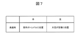
- the determination is made based on the determination condition of FIG. 7 from the attitude information of the driver acquired through the attitude information acquisition unit 109 (handle contact information acquisition unit 109a, scaffold contact information acquisition unit 109b).
- FIG. 8 is a flow chart in the case of determining whether the posture of the driver can respond to the change in the driving force due to the ACC control by using the determination condition of FIG. 7.
- the process proceeds to S409, and both hands of the driver are not located on the steering wheel, that is, If it is determined that one hand or both hands are separated from the steering wheel (not in contact with the steering wheel), the process proceeds to S408.
- the determination method at this time includes the following methods, and it is desirable to make a determination based on the one already installed in the vehicle.
- both hands of the driver are located on the handle, and the handle and the handle It can be determined that both hands of the driver are in contact with each other.
- both hands of the driver are located on the steering wheel, and both hands of the steering wheel and the driver are in contact with each other. Can be determined.
- both hands of the driver are located on the steering wheel based on the sensor information of the capacitance sensor, and both hands of the steering wheel and the driver are in contact with each other. Can be determined.
- the vehicle control device 100 of the present embodiment detects the pressing of the ACC control switch 700, which is the follow-up travel control activation switch, while the vehicle is stopped, the driver of the own vehicle 1 performs the follow-up travel. It is determined whether or not it is possible to respond to changes in the driving force due to control, and if it is determined that it is possible to respond, the follow-up running control is activated.
- the ACC control switch 700 which is the follow-up travel control activation switch
- the ACC control switch 700 which is the follow-up running control start switch, is pressed while the vehicle is stopped, the posture information of the driver of the own vehicle 1 at the time of starting the follow-up running control is acquired, and the driving of the own vehicle 1 is performed. If it is determined that the person and the steering wheel are not in contact with each other, the follow-up driving control is not activated.
- the vehicle control device 100 of the present embodiment since the ACC control is continued (started) only when the driver can respond to the change in the driving force due to the ACC control, it is possible to prevent the vehicle posture from being disturbed and the driver. Can be prevented from becoming dangerous.
- the present invention is not limited to the above-described embodiment, but includes various modified forms.
- the above-described embodiment has been described in detail in order to explain the present invention in an easy-to-understand manner, and is not necessarily limited to the one including all the described configurations.
- it is possible to replace a part of the configuration of one embodiment with the configuration of another embodiment and it is also possible to add the configuration of another embodiment to the configuration of one embodiment.
- each of the above configurations, functions, processing units, processing means, etc. may be realized by hardware by designing a part or all of them by, for example, an integrated circuit. Further, each of the above configurations, functions, and the like may be realized by software by the processor interpreting and executing a program that realizes each function. Information such as programs, tables, and files that realize each function can be stored in a memory, a hard disk, a storage device such as an SSD (Solid State Drive), or a recording medium such as an IC card, an SD card, or a DVD.
- SSD Solid State Drive
- control lines and information lines indicate those that are considered necessary for explanation, and do not necessarily indicate all the control lines and information lines in the product. In practice, it can be considered that almost all configurations are interconnected.
- Vehicle (saddle-type vehicle) 100 Vehicle control device 101 ACC control unit 102 Own vehicle travel information acquisition unit 103 Vehicle speed information acquisition unit 107 Switch operation information acquisition unit 109 Attitude information acquisition unit 109a Handle contact information acquisition unit 109b Scaffold contact information acquisition unit 110 ACC continuation availability determination unit 200 Stereo camera 300 Wheel speed sensor 400 Brake control unit 410 Brake 500 Engine control unit 510 Engine 520 Clutch 530 Transmission 540 Final gear 600 Meter control unit 610 Display device 620 Buzzer 700 ACC control switch (following driving control start switch) 800 navigation device 900 tires
Landscapes
- Engineering & Computer Science (AREA)
- Mechanical Engineering (AREA)
- Transportation (AREA)
- Automation & Control Theory (AREA)
- Physics & Mathematics (AREA)
- Chemical & Material Sciences (AREA)
- Combustion & Propulsion (AREA)
- General Physics & Mathematics (AREA)
- General Engineering & Computer Science (AREA)
- Mathematical Physics (AREA)
- Control Of Driving Devices And Active Controlling Of Vehicle (AREA)
- Control Of Vehicle Engines Or Engines For Specific Uses (AREA)
- Traffic Control Systems (AREA)
Abstract
自動二輪車などの鞍乗型車両において、ACC制御による車両姿勢の乱れを効果的に抑制することのできる車両制御装置を提供する。自車両1を先行車両に追従走行させる追従走行制御を行う鞍乗型車両1の車両制御装置100において、前記追従走行を制御している際の前記自車両1の車速情報に基づいて、前記自車両1の運転者が前記追従走行制御による駆動力の変化に対応可能かを判定し、対応可能と判定した場合、前記追従走行制御を継続する。
Description
本発明は、自動二輪車などの鞍乗型車両に搭載され、先行車両との車間距離や相対速度を安全に保ちつつ、追従走行を行う車両制御装置に関する。
車両の運転操作において、運転者の負担を軽減するため、レーダーやカメラを用いて先行車両との車間距離、及び、相対速度を計測し、運転者がアクセル、ブレーキの操作を行わずとも、自動的に先行車両に追従走行を行うAdaptive Cruise Control(以降、ACCと記載)技術が知られている。
加えて、車両走行中にACC制御を中止するものとして特許文献1がある。特許文献1では、前輪ブレーキを作動するブレーキレバーと、後輪ブレーキを作動するブレーキペダルとを備える自動二輪車において、ブレーキレバーにより前輪ブレーキが作動されるとACC制御を中止する。しかし、片手で操向ハンドルを把持し、他の片手でスイッチ類を操作しているとき、ブレーキペダルを操作することがあり、このような場合は、その作動時間が所定値未満であれば、ACC制御を続行し、その作動時間が所定値以上であれば、ACC制御を中止する技術が開示されている。
走行中に道路が混雑している場合、車両間の距離は狭まるため、低速域での加速と減速を繰り返すことがある。そして、自動二輪車の追従走行機能による低速走行の場合、低速走行でない場合に比べ、停止時の車両の支え、直進保持の車両バランス取りなど、車両の姿勢を保つ運転者の操作が必要である。そのため、運転者操作が困難なときにACC制御による駆動力の変化(すなわち、加減速)が生じた場合、車両の姿勢が乱れ、最悪転倒する恐れがある。運転者操作が困難なときとは、例えば、スイッチ類を操作しているなど、ハンドルから手が離れている状態のことである。
また、停車時からACC制御を開始する際も、車両の姿勢を保つ運転者操作が困難なときにACC制御による駆動力の変化(すなわち、加速)が生じた場合、車両の姿勢が乱れ、車両が転倒してしまうなどの危険が伴う場合がある。
特許文献1では、運転者のブレーキ操作によるACC制御の中止を判定するため、ブレーキ操作をしていないときの判定はしていない。そのため、運転者が意図しないACC制御による駆動力の変化が生じた場合、車両の姿勢が乱れる可能性がある。
また、特許文献1では、ACC制御の中止の判定をしており、ACC制御を中止した後に、再度ACC制御を開始したい場合は、ACC制御を開始する再操作が必要であり、機能の利便性を損ねる懸念もある。
本発明は、上記事情に鑑みてなされたもので、その目的とするところは、自動二輪車などの鞍乗型車両において、ACC制御による車両姿勢の乱れを効果的に抑制することのできる車両制御装置を提供することにある。
前記の問題を解決するため、本発明に係る車両制御装置は、自車両を先行車両に追従走行させる追従走行制御を行う鞍乗型車両の車両制御装置において、前記追従走行を制御している際の前記自車両の車速情報に基づいて、前記自車両の運転者が前記追従走行制御による駆動力の変化に対応可能かを判定し、対応可能と判定した場合、前記追従走行制御を継続することを特徴とする。
すなわち、本発明の車両制御装置は、例えば低速域において運転者がACC制御による駆動力の変化に対応できない状態での駆動力変化を防ぐために、自車両の車速情報に基づいて、ACC制御による駆動力変化に対応可能かを判定し、対応可能な場合、追従走行制御を継続する。また、判定した結果、対応不可であり、ACC制御による駆動力変化により危険が伴う可能性があると判定した場合は、ACC制御による駆動力の変化を抑止、またはACC制御を中断する。
本発明の車両制御装置によれば、運転者がACC制御による駆動力の変化に対応可能な場合のみACC制御を継続するので、車両姿勢の乱れを防ぐことができ、運転者が危険な状態にならないようにすることができる。
また、ACC制御による駆動力の変化により危険が伴うが、ACC制御による駆動力変化を抑止することで危険が伴わない場合は中断しないので、ACC制御の中断による再操作を不要とし、利便性の低下を防ぐことができる。
上記した以外の課題、構成及び効果は、以下の実施形態の説明により明らかにされる。
以下、本発明の実施形態を図面を参照しながら説明する。
[第1の実施例]
図1は、本発明の第1の実施例における車両制御装置を備えた車両のシステム構成を示す図である。本実施例の車両制御装置100は、自動二輪車などの鞍乗型車両(以下、車両1もしくは自車両1と称する)に搭載され、先行車両との車間距離や相対速度を安全に保ちつつ、先行車両に追従走行を行う追従走行機能(ACC機能)を有する。
図1は、本発明の第1の実施例における車両制御装置を備えた車両のシステム構成を示す図である。本実施例の車両制御装置100は、自動二輪車などの鞍乗型車両(以下、車両1もしくは自車両1と称する)に搭載され、先行車両との車間距離や相対速度を安全に保ちつつ、先行車両に追従走行を行う追従走行機能(ACC機能)を有する。
車両制御装置100は、ステレオカメラ200と接続され、ステレオカメラ200で計測した他車両などとの車間距離、道路曲率、車両バンク角は、車両制御装置100へ通信によって送信される。また、車両制御装置100は、車輪に取り付けられた車輪速センサ300と接続され、車輪速センサ300でタイヤ900の回転数を計測し、計測した回転数から換算した自車両の速度(車速)は、車両制御装置100へ送信される。また、車両制御装置100は、ACCコントロールスイッチ700と接続され、運転者のスイッチ操作情報が車両制御装置100へ送信されることで、運転者のACC制御開始、ACC制御解除、ACC走行時の設定速度を判断する。この構成により、車両制御装置100は、車間距離、自車速度、ACC走行時の設定速度を得ることで、制御量の計算を行う。
また、車両制御装置100は、算出した制御量に基づいて、ブレーキ410での制御量、エンジン510での制御量を算出するとともに、運転者への報知方法を決定する。
算出したブレーキ410での制御量は、車両制御装置100に接続したブレーキコントロールユニット400に通信で送信され、ブレーキコントロールユニット400は、アクチュエータであるブレーキ410を動作させ、タイヤ900に対する摩擦力を用いて車両1の減速度を制御する。
更に、エンジン510での制御量は、車両制御装置100に接続したエンジンコントロールユニット500に通信で送信され、エンジンコントロールユニット500は、エンジン510を動作させる。エンジン510で発生した加速力は、クラッチ520、トランスミッション530、ファイナルギア540を通して倍力され、タイヤ900に伝えられることで、車両1の加速度を制御する。
更に、車両制御装置100で決定した運転者への報知方法は、車両制御装置100に接続されたメータコントロールユニット600に通信で送信されることで、メータコントロールユニット600によるブザー620を用いての警告や、表示装置610を用いての制御状態通知などを行う。
また、車両制御装置100は、ナビ装置800と接続され、ナビ装置800は、地図情報などから車両前方の道路曲率を取得して車両制御装置100へ送信する。
そして、上述する接続は、CAN(Car Area Network)を用いて行われる。
なお、車両1の構成は上述する例に限られない。例えば、ステレオカメラ200に代えて、ミリ波レーダー、単眼カメラ、ソナー、レーザーレーダーなどの外界認識センサを用いて自車両周辺を監視し、他車両などとの車間距離や相対速度を計測してもよい。また、車輪速センサ300を用いた方法以外の方法で、自車速度を計測してもよい。また、エンジン510を用いる車両以外の、電気車両やハイブリッド車両、水素車両などであってもよい。
図2は、本発明の第1の実施例における車両制御装置のACC機能に係る機能ブロック図である。なお、車両制御装置100は、内部にCPU、ROM、RAM等を備えたマイクロコンピュータ(マイコンとも称する)として構成されており、CPUは、ROMに格納された各種プログラムを実行し、CPUが実行されることで生成される情報はRAMに一時的に格納される。
本実施例の車両制御装置100は、ACC制御を実現するための機能ブロックとして、基本的に、自車両走行情報取得部102と、車速情報取得部103と、スイッチ操作情報取得部107と、姿勢情報取得部109と、ACC制御部101と、ACC継続可否判定部110と、を備える。
自車両走行情報取得部102は、ステレオカメラ200から、ACC制御時の目標となる前方走行車両との相対速度や車間距離情報などの自車両走行情報を取得する。また、自車両走行情報取得部102は、ナビ装置800から、車両前方の道路曲率を自車両走行情報として取得してもよい。
車速情報取得部103は、車輪速センサ300から、タイヤ900の回転数を計測して得た自車両1の車速情報を取得する。
スイッチ操作情報取得部107は、ACCコントロールスイッチ700から、運転者のACC制御開始、ACC制御解除、ACC走行時の設定速度などのスイッチ操作情報を取得する。
ACC制御部101は、自車両走行情報取得部102、車速情報取得部103、スイッチ操作情報取得部107で得た情報を基に、ACC制御時の目標となる前方走行車両に追従走行を行うように、ブレーキ410での制御量(制動指示)、エンジン510での制御量(駆動指示)を算出するとともに、運転者への報知方法を決定する。ACC制御部101は、算出したブレーキ410での制御量(制動指示)をブレーキコントロールユニット400に通信で送信し、算出したエンジン510での制御量(駆動指示)をエンジンコントロールユニット500に通信で送信し、ACC制御時の車両1の減速度及び加速度(すなわち、駆動力)を制御する。また、ACC制御部101は、決定した運転者への報知方法をメータコントロールユニット600に通信で送信する。
姿勢情報取得部109は、当該車両(鞍乗型車両)1に搭乗する運転者の姿勢情報(運転姿勢情報)を取得する。また、姿勢情報取得部109は、ハンドル接触情報取得部109aと足場接触情報取得部109bとを含んで構成される。ハンドル接触情報取得部109aは、運転姿勢においてハンドルと運転者が接触しているか否かの情報を含むハンドル接触情報を取得する。足場接触情報取得部109bは、運転姿勢において足場と運転者が接触しているか否かの情報を含む足場接触情報を取得する。なお、ハンドル接触情報取得部109aと足場接触情報取得部109bとを含む姿勢情報取得部109については後で詳細に説明する。
ACC継続可否判定部110は、ACC制御部101、自車両走行情報取得部102、車速情報取得部103、及び姿勢情報取得部109で得られた情報を基に、ACC制御による追従走行の継続の可否、すなわち、ACC制御による追従走行の継続もしくは中断(中止)を判定する。詳しくは、ACC継続可否判定部110は、姿勢情報取得部109などで得られた情報を基に、当該車両(鞍乗型車両)1に搭乗する運転者(の運転姿勢)がACC制御による駆動力の変化に対応可能か否かを判定し、その判定結果を基に、ACC制御による追従走行の継続、ACC制御による加減速(駆動力の変化に相当)の抑止、またはACC制御による追従走行の中断を判定する。また、ACC継続可否判定部110は、その判定結果に応じた制御指示を生成してACC制御部101に送信する。
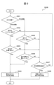
次に、車両制御装置100(のACC継続可否判定部110)で行うACC制御の継続判定について、図3のフローチャートを用いて説明する。図3は、車両走行中に運転者がACCコントロールスイッチ700を押下し、ACC走行を開始した場合のフロー図である。
S201では、ACC走行中に制駆動指示をACC制御部101から受信する。
S202では、タイヤ900の回転数を計測して得た自車両1の車速情報を車速情報取得部103を介して取得する。
S203では、S202で取得した自車両1の車速が所定値以上(例えば、10km/h以上)の場合は、S204に移行し、自車両1の車速が所定値未満である低速域の場合は、S205に移行する。この時、自車速が低速域の場合のみ、運転者がACC制御による駆動力の変化に対応可能かを判定し、車両のバランスがとりやすい、比較的安定した走行を可能とする車速(例えば、100km/h)では判定しないため、機能の利便性の低下を防ぐことができる。換言すれば、本例では、自車両1の車速が所定値以上である通常速度又は高速度の場合と自車両1の車速が所定値未満である低速度の場合とで、AAC制御の継続判定基準を変える(本例では、通常速度又は高速度の場合は判定しない)ようになっている。
S204では、ACC制御による車両走行を継続し、本処理を終了する。
S205では、ステレオカメラ200で計測したACC制御時の目標となる前方走行車両との相対速度や車間距離情報などの自車両走行情報を自車両走行情報取得部102を介して取得するとともに、当該車両1に搭乗する運転者の姿勢情報を姿勢情報取得部109を介して取得する。
S206では、S205で取得した前方走行車両との相対速度や車間距離情報などの自車両走行情報と運転者の姿勢情報を基に、自車両1の運転者(の運転姿勢)がACC制御による駆動力の変化に対応可能かを判定し(後で説明)、対応可能と判定した場合は、S204に移行し、対応不可であり、ACC制御を継続した場合に危険が伴うと判定した場合は、S207に移行する。この時、S204では、ACC制御による駆動力の変化に対応可能な場合のみACC制御を継続するので、ACC制御による車両姿勢の乱れを防ぐことができ、運転者が危険な状態にならないようにすることができる。
S206での自車両1の運転者がACC制御による駆動力の変化に対応可能かの具体的な判定方法について、図4、図5を用いて説明する。
判定する際は、姿勢情報取得部109(のハンドル接触情報取得部109a、足場接触情報取得部109b)を介して取得した運転者の姿勢情報より、図4の判定条件に基づいて判定する。
自車両1の車速が低速域からの加速時(つまり、S201で受信したACC制御による制駆動指示が加速)は、両手がハンドルに位置しており、両足が足場(例えば、フットペダル)に位置している(接触している)場合、自車両1の運転者がACC制御による駆動力の変化に対応可能と判定する。この時、運転者が片手で操向ハンドルを把持し、他の片手でスイッチ類を操作しているときなど、片手運転時のACC制御による駆動力の変化を生じさせないため、操向ハンドルの乱れを防ぎ、運転者の姿勢の乱れを防ぐことができる。そして、自立走行が難しいと判断し、足を地面につけようと片足を足場から離しているときの運転者の意図しない加速を防ぎ、地面と足との接触による運転姿勢の乱れなど、運転者を危険な状態にしない。
自車両1の車速が低速域からの減速時(つまり、S201で受信したACC制御による制駆動指示が減速)は、両手がハンドルに位置しており、片足もしくは両足が足場から離れている(足場と非接触である)場合、自車両1の運転者がACC制御による駆動力の変化に対応可能と判定する。この時、両手の位置に関しては、加速時と同様、運転者の姿勢を乱れなくすることができる。そして、足の位置に関しては、少なくとも片足が足場から離れたときのみ減速を許容することで、低速域からの減速が生じて車両のバランス取りが困難となった場合でも、すぐに足を地面につけて車両のバランスを取ることができる。
図5は、図4の判定条件を用いて、運転者の姿勢がACC制御による駆動力の変化に対応可能かを判定するフロー図である。
S401では、S201で受信したACC制御による制駆動指示が加速の場合、S402に移行し、S201で受信したACC制御による制駆動指示が減速の場合は、S405に移行する。
S402では、S205で取得した運転者の運転姿勢情報より、運転者の両手がハンドルに位置していると判定した場合は、S403に移行し、運転者の両手がハンドルに位置していない、すなわち片手、または両手がハンドルから離れていると判定した場合は、S407に移行する。この時の判定方法は、以下のような方法が挙げられ、既に車両に搭載されているもので判定することが望ましい。
例えば、ステレオカメラ搭載の加速度センサ(Gセンサ)を用い、加速度センサ(Gセンサ)で検知される走行中の縦方向の移動距離が所定値以下の場合、運転者の両手がハンドルに位置し、ハンドルと運転者の両手とが接触していると判定することができる。すなわち、この場合、ハンドルと運転者の手の接触を検出するハンドル接触検出手段として、車両の前後、左右、または上下の動きを検知するステレオカメラ搭載の加速度センサ(Gセンサ)を用い、前記した姿勢情報取得部109のハンドル接触情報取得部109aによって、ハンドル接触検出手段である加速度センサで検知した走行中の車両の各々の方向への移動量を取得する。そして、ACC継続可否判定部110は、姿勢情報取得部109のハンドル接触情報取得部109aを介して取得した走行中の車両の各々の方向への移動量(ハンドルと運転者の接触情報に対応)を基に、運転者の両手がハンドルに位置し、ハンドルと運転者の両手とが接触していると判定することができる。
また、ステレオカメラ視点を用い、ステレオカメラ視点の時間移動周波数帯が所定値(例えば3Hz以下)以下の場合、運転者の両手がハンドルに位置し、ハンドルと運転者の両手とが接触していると判定することができる。すなわち、この場合、ハンドルと運転者の手の接触を検出するハンドル接触検出手段として、ステレオカメラ視点を用い、前記した姿勢情報取得部109のハンドル接触情報取得部109aによって、ハンドル接触検出手段であるステレオカメラ視点の時間移動周波数帯を取得する。そして、ACC継続可否判定部110は、姿勢情報取得部109のハンドル接触情報取得部109aを介して取得したステレオカメラ視点の時間移動周波数帯(ハンドルと運転者の接触情報に対応)が所定値(例えば3Hz以下)以下の場合、運転者の両手がハンドルに位置し、ハンドルと運転者の両手とが接触していると判定することができる。
また、ハンドルに備えられた静電容量センサ(接触検出センサとも称する)を用い、静電容量センサのセンサ情報により、運転者の両手がハンドルに位置し、ハンドルと運転者の両手とが接触していると判定することができる。すなわち、この場合、ハンドルと運転者の手の接触を検出するハンドル接触検出手段として、ハンドルに備えられた静電容量センサを用い、前記した姿勢情報取得部109のハンドル接触情報取得部109aによって、ハンドル接触検出手段である静電容量センサから得たセンサ情報を取得する。そして、ACC継続可否判定部110は、姿勢情報取得部109のハンドル接触情報取得部109aを介して取得した静電容量センサのセンサ情報(ハンドルと運転者の接触情報に対応)に基づいて、運転者の両手がハンドルに位置し、ハンドルと運転者の両手とが接触していると判定することができる。
S403では、S205で取得した運転者の運転姿勢情報より、運転者の両足が足場に位置していると判定した場合は、S404に移行し、運転者の両足が足場に位置していない、すなわち片足、または両足が地面に近い位置にある可能性があると判定した場合は、S407に移行する。この時の判定方法は、足場に備えられたタッチセンサ(接触検出センサとも称する)などを用いた方法が挙げられ、既に車両に搭載されているもので判定することが望ましい。すなわち、この場合、足場と運転者の足との接触を検出する足場接触検出手段として、タッチセンサを用い、前記した姿勢情報取得部109の足場接触情報取得部109bによって、足場接触検出手段であるタッチセンサから得たセンサ情報を取得する。そして、ACC継続可否判定部110は、姿勢情報取得部109の足場接触情報取得部109bを介して取得したタッチセンサのセンサ情報(足場と運転者の接触情報に対応)に基づいて、運転者の両足が足場に位置し、足場と運転者の両足とが接触していると判定することができる。
S404では、S205で取得した運転者の運転姿勢がACC制御による駆動力の変化に対応可能と判定し(図4の加速時参照)、本処理を終了する。この時、運転者の両手がハンドルに位置し、かつ両足が足場にあるときのみACC制御による走行を継続するので、低速域からの加速による駆動力の変化が生じても、両腕でハンドルを把持しているため、ハンドル操作の乱れを防ぐことができる。また、地面と足との接触による運転姿勢の乱れも防ぐことができる。
S405では、S205で取得した運転者の運転姿勢情報より、運転者の両手がハンドルに位置していると判定した場合は、S406に移行し、運転者の両手がハンドルに位置していない、すなわち片手、または両手がハンドルから離れていると判定した場合は、S407に移行する。
S406では、S205で取得した運転者の運転姿勢情報より、運転者の片足、もしくは両足が足場から離れていると判定した場合は、S404に移行し、運転者の足が足場から離れていない、すなわち両足が足場に位置していると判定した場合は、S407に移行する。
S404では、S205で取得した運転者の運転姿勢がACC制御による駆動力の変化に対応可能と判定し(図4の減速時参照)、本処理を終了する。この時、運転者の両手がハンドルに位置し、かつ足が足場から離れているときのみACC制御による走行を継続するので、低速域からの減速による駆動力の変化が生じても、両腕でハンドルを把持しているため、ハンドル操作の乱れを防ぐことができ、減速により自車両のバランス取りが困難となった場合でも、すぐに足を地面につけて車両のバランスを取ることができ、運転者姿勢の乱れを防ぐことができる。
S407では、ACC制御による駆動力変化が生じた場合、危険が伴う運転者の運転姿勢が所定時間を超過した場合、S408に移行する。一方、ACC制御による駆動力変化によって危険が伴う運転者の運転姿勢の状態が所定時間以内の場合は、S401に戻り、ACC制御による追従走行を継続する。
S408では、ACC制御による駆動力変化が生じた場合、危険が伴う可能性があるため、ACC制御による駆動力変化に対応不可と判定し、本処理を終了する。この時、ACC制御による駆動力の変化により運転者に危険が伴う運転姿勢が所定時間を超過した場合のみ、ACC制御による追従走行を継続しない(換言すれば、ACC制御による駆動力の変化により運転者に危険が伴う運転姿勢が所定時間以内の場合は、ACC制御による追従走行を継続する)ので、機能の利便性の低減を防ぐことができる。
図3に戻り、S207では(ACC制御による駆動力変化に対応不可であり、ACC制御を継続した場合に危険が伴うと判定した場合)、S205で取得した前方走行車両との相対速度や車間距離情報などの自車両走行情報を基に、ACC制御による加減速を抑止することでACC制御による走行を継続できるかを判定する。例えば、前方走行車両との距離が十分にあるため、ACC制御による走行を継続できると判定した場合は、S208に移行し、例えば、前方走行車両との距離が近いため、ACC制御による走行を継続した場合に危険が伴うと判定した場合は、S209に移行する。この時、ACC制御による加減速を抑止することでACC制御による走行を継続することができ、機能の利便性の低下を防ぐことができる。
S208では、S207でACC制御による加減速を抑止することでACC制御による走行を継続できるかを判定したため、ACC制御による加減速を抑止してS204に移行する。
S209では、ACC制御による走行を継続した場合、危険が伴うと判定したため、ACC制御による走行を中断し、本処理を終了する。
以上で説明したように、本実施例の車両制御装置100は、自車両1を先行車両に追従走行させる追従走行制御を行う鞍乗型車両1の車両制御装置100において、前記追従走行を制御している際の前記自車両1の車速情報に基づいて、前記自車両1の運転者が前記追従走行制御による駆動力の変化に対応可能かを判定し、対応可能と判定した場合、前記追従走行制御を継続する。
また、前記自車両1の運転者が前記追従走行制御による駆動力の変化に対応可能かを判定し、対応不可と判定した場合は、前記追従走行制御による駆動力の変化を抑止、または前記追従走行制御を中断する。
また、前記自車両1の運転者の姿勢情報を取得する姿勢情報取得部109を備え、前記追従走行を制御している際の前記自車両1の車速情報と前記姿勢情報取得部109で取得した前記自車両1の運転者の姿勢情報とから、前記追従走行制御の継続を判定する。
すなわち、本実施例の車両制御装置100は、例えば低速域において運転者がACC制御による駆動力の変化に対応できない状態での駆動力変化を防ぐために、自車両1の車速情報に基づいて、ACC制御による駆動力変化に対応可能かを判定し、対応可能な場合、追従走行制御を継続する。また、判定した結果、対応不可であり、ACC制御による駆動力変化により危険が伴う可能性があると判定した場合は、ACC制御による駆動力の変化を抑止、またはACC制御を中断する。
本実施例の車両制御装置100によれば、運転者がACC制御による駆動力の変化に対応可能な場合のみACC制御を継続するので、車両姿勢の乱れを防ぐことができ、運転者が危険な状態にならないようにすることができる。
また、ACC制御による駆動力の変化により危険が伴うが、ACC制御による駆動力変化を抑止することで危険が伴わない場合は中断しないので、ACC制御の中断による再操作を不要とし、利便性の低下を防ぐことができる。
[第2の実施例]
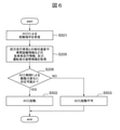
本発明の第2の実施例における車両制御装置100(のACC継続可否判定部110)で行うACC制御の継続判定の内容について、図6のフローチャートを用いて説明する。図6は、車両停車中に運転者がACCコントロールスイッチ700を押下した場合のフロー図である。なお、本第2の実施例における車両(鞍乗型車両)1の構成や車両制御装置100の機能ブロック構成は、上述した第1の実施例とほぼ同じである。
本発明の第2の実施例における車両制御装置100(のACC継続可否判定部110)で行うACC制御の継続判定の内容について、図6のフローチャートを用いて説明する。図6は、車両停車中に運転者がACCコントロールスイッチ700を押下した場合のフロー図である。なお、本第2の実施例における車両(鞍乗型車両)1の構成や車両制御装置100の機能ブロック構成は、上述した第1の実施例とほぼ同じである。
S501では、ACC制御の起動指示を受信する。なお、ACC制御による起動指示は、スイッチ操作情報取得部107から受信してもよいし、ACC制御部101から受信してもよい。
S205では、ステレオカメラ200で計測したACC制御時の目標となる前方走行車両との相対速度や車間距離情報などの自車両走行情報を自車両走行情報取得部102を介して取得するとともに、当該車両1に搭乗する運転者の姿勢情報を姿勢情報取得部109を介して取得する。
S206では、S205で取得した前方走行車両との相対速度や車間距離情報などの自車両走行情報と運転者の姿勢情報を基に、自車両1の運転者(の運転姿勢)がACC制御による駆動力の変化に対応可能かを判定し(後で説明)、対応可能と判定した場合は、S502に移行し、対応不可であり、ACC制御を継続(起動)した場合に危険が伴うと判定した場合は、S503に移行する。この時、S502では、ACC制御による駆動力の変化に対応可能な場合のみACC制御を継続(起動)するので、ACC制御による車両姿勢の乱れを防ぐことができ、運転者が危険な状態にならないようにすることができる。
S206での自車両1の運転者がACC制御による駆動力の変化に対応可能かの具体的な判定方法について、図7、図8を用いて説明する。
判定する際は、姿勢情報取得部109(のハンドル接触情報取得部109a、足場接触情報取得部109b)を介して取得した運転者の姿勢情報より、図7の判定条件に基づいて判定する。
停車状態からの発進時は、両手がハンドルに位置、片足のみが足場にある場合、自車両1の運転者がACC制御による駆動力の変化に対応可能と判定する。この時、運転者が片手で操向ハンドルを把持し、他の片手でスイッチ類を操作しているときなど、片手運転時のACC制御による駆動力の変化を防ぐことができ、操向ハンドルの乱れを防ぐことができる。そのため、運転者の姿勢に乱れを生じさせない。そして、片足が足場にある場合のみ対応可能と判定するため、両足が地面についているときに運転者が誤ってACCコントロールスイッチ700を押下した場合の誤発進を防ぐことができ、運転者を危険な状態にしない。
図8は、図7の判定条件を用いて、運転者の姿勢がACC制御による駆動力の変化に対応可能かを判定する場合のフロー図である。
S402では、S205で取得した運転者の運転姿勢情報より、運転者の両手がハンドルに位置していると判定した場合は、S409に移行し、運転者の両手がハンドルに位置していない、すなわち片手、または両手がハンドルから離れている(ハンドルと非接触である)と判定した場合は、S408に移行する。この時の判定方法は、以下のような方法が挙げられ、既に車両に搭載されているもので判定することが望ましい。
例えば、ステレオカメラ搭載の加速度センサ(Gセンサ)を用い、加速度センサ(Gセンサ)で検知される走行中の縦移動距離が所定値以下の場合、運転者の両手がハンドルに位置し、ハンドルと運転者の両手とが接触していると判定することができる。
また、ステレオカメラ視点を用い、ステレオカメラ視点の時間移動周波数帯が所定値(例えば3Hz以下)以下の場合、運転者の両手がハンドルに位置し、ハンドルと運転者の両手とが接触していると判定することができる。
また、ハンドルに備えられた静電容量センサ(接触検出センサ)を用い、静電容量センサのセンサ情報により、運転者の両手がハンドルに位置し、ハンドルと運転者の両手とが接触していると判定することができる。
S409では、S205で取得した運転者の運転姿勢情報より、運転者の片足が足場に位置していると判定した場合は、S404に移行し、運転者の足が足場に位置していない、すなわち両足が地面に近い位置にある可能性があると判定した場合は、S408に移行する。この時の判定方法は、足場に備えられたタッチセンサ(接触検出センサ)などを用いた方法が挙げられ、既に車両に搭載されているもので判定することが望ましい。
S404では、S205で取得した運転者の運転姿勢がACC制御による駆動力の変化に対応可能と判定し(図7の発進時参照)、本処理を終了する。この時、運転者の両手がハンドルに位置し、かつ片足が足場にあるときのみACC制御による走行を継続(起動)するので、停車状態からの加速による駆動力の変化が生じたとしても、両腕でハンドルを把持しているため、ハンドル操作の乱れを防ぐことができる。また、片足を足場に乗せた発進準備をしていないときの意図しないACC制御による駆動力変化を防ぎ、運転者を危険な状態にしない。
S408では、ACC制御による駆動力変化が生じた場合、危険が伴う可能性があるため、ACC制御による駆動力の変化に対応不可と判定し、本処理を終了する。
図6に戻り、S502では、S206で運転者の運転姿勢がACC制御による駆動力の変化に対応可能と判定したため、ACC制御による走行を開始し、本処理を終了する。
S503では、ACC制御による走行を開始した場合、危険が伴うと判定したため、ACC制御による起動指示をキャンセルし(つまり、ACC制御を起動せずに)、本処理を終了する。
以上で説明したように、本実施例の車両制御装置100は、車両停車中に追従走行制御起動スイッチであるACCコントロールスイッチ700の押下を検知した場合、前記自車両1の運転者が前記追従走行制御による駆動力の変化に対応可能かを判定し、対応可能と判定した場合は、前記追従走行制御を起動する。
また、車両停車中に追従走行制御起動スイッチであるACCコントロールスイッチ700の押下を検知した場合、追従走行制御起動時の前記自車両1の運転者の姿勢情報を取得し、前記自車両1の運転者とハンドルとが非接触と判定された場合は、前記追従走行制御を起動しない。
本実施例の車両制御装置100によれば、運転者がACC制御による駆動力の変化に対応可能な場合のみACC制御を継続(起動)するので、車両姿勢の乱れを防ぐことができ、運転者が危険な状態にならないようにすることができる。
なお、本発明は上記した実施形態に限定されるものではなく、様々な変形形態が含まれる。例えば、上記した実施形態は本発明を分かりやすく説明するために詳細に説明したものであり、必ずしも説明した全ての構成を備えるものに限定されるものではない。また、ある実施形態の構成の一部を他の実施形態の構成に置き換えることが可能であり、また、ある実施形態の構成に他の実施形態の構成を加えることも可能である。また、各実施形態の構成の一部について、他の構成の追加・削除・置換をすることが可能である。
また、上記の各構成、機能、処理部、処理手段等は、それらの一部又は全部を、例えば集積回路で設計する等によりハードウェアで実現してもよい。また、上記の各構成、機能等は、プロセッサがそれぞれの機能を実現するプログラムを解釈し、実行することによりソフトウェアで実現してもよい。各機能を実現するプログラム、テーブル、ファイル等の情報は、メモリや、ハードディスク、SSD(Solid State Drive)等の記憶装置、または、ICカード、SDカード、DVD等の記録媒体に置くことができる。
また、制御線や情報線は説明上必要と考えられるものを示しており、製品上必ずしも全ての制御線や情報線を示しているとは限らない。実際には殆ど全ての構成が相互に接続されていると考えてもよい。
1 車両(鞍乗型車両)
100 車両制御装置
101 ACC制御部
102 自車両走行情報取得部
103 車速情報取得部
107 スイッチ操作情報取得部
109 姿勢情報取得部
109a ハンドル接触情報取得部
109b 足場接触情報取得部
110 ACC継続可否判定部
200 ステレオカメラ
300 車輪速センサ
400 ブレーキコントロールユニット
410 ブレーキ
500 エンジンコントロールユニット
510 エンジン
520 クラッチ
530 トランスミッション
540 ファイナルギア
600 メータコントロールユニット
610 表示装置
620 ブザー
700 ACCコントロールスイッチ(追従走行制御起動スイッチ)
800 ナビ装置
900 タイヤ
Claims (15)
- 自車両を先行車両に追従走行させる追従走行制御を行う鞍乗型車両の車両制御装置において、
前記追従走行を制御している際の前記自車両の車速情報に基づいて、前記自車両の運転者が前記追従走行制御による駆動力の変化に対応可能かを判定し、対応可能と判定した場合、前記追従走行制御を継続することを特徴とする車両制御装置。 - 前記自車両の運転者が前記追従走行制御による駆動力の変化に対応可能かを判定し、対応不可と判定した場合は、前記追従走行制御による駆動力の変化を抑止、または前記追従走行制御を中断することを特徴とする、請求項1に記載の車両制御装置。
- 前記自車両の運転者の姿勢情報を取得する姿勢情報取得部を備え、
前記追従走行を制御している際の前記自車両の車速情報と前記姿勢情報取得部で取得した前記自車両の運転者の姿勢情報とから、前記追従走行制御の継続を判定することを特徴とする、請求項1に記載の車両制御装置。 - 前記自車両のハンドルと運転者の接触情報を取得するハンドル接触情報取得部を備え、
前記ハンドル接触情報取得部で得た接触情報に基づいて、前記自車両の運転者の運転姿勢が前記追従走行制御による駆動力の変化に対応可能かを判定し、対応可能と判定した場合、前記追従走行制御を継続することを特徴とする、請求項1に記載の車両制御装置。 - 前記自車両の足場と運転者の接触情報を取得する足場接触情報取得部を備え、
前記足場接触情報取得部で得た接触情報に基づいて、前記自車両の運転者の運転姿勢が前記追従走行制御による駆動力の変化に対応可能かを判定し、対応可能と判定した場合、前記追従走行制御を継続することを特徴とする、請求項1に記載の車両制御装置。 - 前記追従走行制御による減速時は、前記自車両の運転者の片足もしくは両足が足場から離れていると判定された場合、前記追従走行制御を継続することを特徴とする、請求項5に記載の車両制御装置。
- 前記追従走行制御による加速時は、前記自車両の運転者の両足と足場とが接触していると判定された場合、前記追従走行制御を継続することを特徴とする、請求項5に記載の車両制御装置。
- 前記ハンドル接触情報取得部は、前記自車両の前後、左右、または上下の動きを検知するセンサから、走行中の前記自車両の各々の方向への移動量を取得し、
取得した走行中の前記自車両の各々の方向への移動量を基に、前記自車両の運転者とハンドルとが接触していると判定することを特徴とする、請求項4に記載の車両制御装置。 - 前記ハンドル接触情報取得部は、ステレオカメラ視点の時間移動周波数帯を取得し、
取得したステレオカメラ視点の時間移動周波数帯が所定値以下の場合、前記自車両の運転者とハンドルとが接触していると判定することを特徴とする、請求項4に記載の車両制御装置。 - 前記ハンドル接触情報取得部は、前記ハンドルに備えられたハンドルと運転者の手との接触を検出する接触検出センサのセンサ情報を取得し、
取得した前記接触検出センサのセンサ情報に基づいて、前記自車両の運転者の手とハンドルとが接触していると判定することを特徴とする、請求項4に記載の車両制御装置。 - 前記足場接触情報取得部は、前記足場に備えられた足場と運転者の足との接触を検出する接触検出センサのセンサ情報を取得し、
取得した前記接触検出センサのセンサ情報に基づいて、前記自車両の運転者の足と足場が接触していると判定することを特徴とする、請求項5に記載の車両制御装置。 - 前記自車両の運転者の運転姿勢が前記追従走行制御による駆動力の変化に対応可能かを判定した際に、
対応不可と判定した運転姿勢の状態が所定時間以内の場合は、前記追従走行制御を継続することを特徴とする、請求項2に記載の車両制御装置。 - 前記自車両の車速が所定値以上の場合と前記自車両の車速が所定値未満の場合とで、前記追従走行制御の継続判定基準を変えることを特徴とする、請求項1に記載の車両制御装置。
- 車両停車中に追従走行制御起動スイッチの押下を検知した場合、前記自車両の運転者が前記追従走行制御による駆動力の変化に対応可能かを判定し、対応可能と判定した場合は、前記追従走行制御を起動することを特徴とする、請求項1に記載の車両制御装置。
- 車両停車中に追従走行制御起動スイッチの押下を検知した場合、追従走行制御起動時の前記自車両の運転者の姿勢情報を取得し、前記自車両の運転者とハンドルとが非接触と判定された場合は、前記追従走行制御を起動しないことを特徴とする、請求項1に記載の車両制御装置。
Applications Claiming Priority (2)
| Application Number | Priority Date | Filing Date | Title |
|---|---|---|---|
| JP2020-136754 | 2020-08-13 | ||
| JP2020136754A JP7403412B2 (ja) | 2020-08-13 | 2020-08-13 | 車両制御装置 |
Publications (1)
| Publication Number | Publication Date |
|---|---|
| WO2022034707A1 true WO2022034707A1 (ja) | 2022-02-17 |
Family
ID=80247106
Family Applications (1)
| Application Number | Title | Priority Date | Filing Date |
|---|---|---|---|
| PCT/JP2021/008636 Ceased WO2022034707A1 (ja) | 2020-08-13 | 2021-03-05 | 車両制御装置 |
Country Status (2)
| Country | Link |
|---|---|
| JP (1) | JP7403412B2 (ja) |
| WO (1) | WO2022034707A1 (ja) |
Cited By (1)
| Publication number | Priority date | Publication date | Assignee | Title |
|---|---|---|---|---|
| JPWO2023170487A1 (ja) * | 2022-03-09 | 2023-09-14 |
Families Citing this family (2)
| Publication number | Priority date | Publication date | Assignee | Title |
|---|---|---|---|---|
| WO2025069500A1 (ja) * | 2023-09-28 | 2025-04-03 | アルプスアルパイン株式会社 | 把持検出システム |
| JP2026065408A (ja) * | 2024-10-03 | 2026-04-15 | ヤマハ発動機株式会社 | リーン車両 |
Citations (6)
| Publication number | Priority date | Publication date | Assignee | Title |
|---|---|---|---|---|
| JPS62149518A (ja) * | 1985-12-23 | 1987-07-03 | Honda Motor Co Ltd | 車両用定速走行装置 |
| JP2009184579A (ja) * | 2008-02-07 | 2009-08-20 | Keihin Corp | 自動二輪車のクルーズコントロール装置 |
| JP2010100107A (ja) * | 2008-10-21 | 2010-05-06 | Toyota Motor Corp | 走行制御装置 |
| JP2015093662A (ja) * | 2013-11-14 | 2015-05-18 | オムロンオートモーティブエレクトロニクス株式会社 | 電動パワーステアリング制御装置および制御方法、電動パワーステアリング装置 |
| JP2018154273A (ja) * | 2017-03-21 | 2018-10-04 | ローベルト ボッシュ ゲゼルシャフト ミット ベシュレンクテル ハフツング | 制御装置及び制御方法 |
| JP2019014468A (ja) * | 2017-07-07 | 2019-01-31 | 株式会社ジェイテクト | 操舵装置 |
-
2020
- 2020-08-13 JP JP2020136754A patent/JP7403412B2/ja active Active
-
2021
- 2021-03-05 WO PCT/JP2021/008636 patent/WO2022034707A1/ja not_active Ceased
Patent Citations (6)
| Publication number | Priority date | Publication date | Assignee | Title |
|---|---|---|---|---|
| JPS62149518A (ja) * | 1985-12-23 | 1987-07-03 | Honda Motor Co Ltd | 車両用定速走行装置 |
| JP2009184579A (ja) * | 2008-02-07 | 2009-08-20 | Keihin Corp | 自動二輪車のクルーズコントロール装置 |
| JP2010100107A (ja) * | 2008-10-21 | 2010-05-06 | Toyota Motor Corp | 走行制御装置 |
| JP2015093662A (ja) * | 2013-11-14 | 2015-05-18 | オムロンオートモーティブエレクトロニクス株式会社 | 電動パワーステアリング制御装置および制御方法、電動パワーステアリング装置 |
| JP2018154273A (ja) * | 2017-03-21 | 2018-10-04 | ローベルト ボッシュ ゲゼルシャフト ミット ベシュレンクテル ハフツング | 制御装置及び制御方法 |
| JP2019014468A (ja) * | 2017-07-07 | 2019-01-31 | 株式会社ジェイテクト | 操舵装置 |
Cited By (2)
| Publication number | Priority date | Publication date | Assignee | Title |
|---|---|---|---|---|
| JPWO2023170487A1 (ja) * | 2022-03-09 | 2023-09-14 | ||
| JP7872835B2 (ja) | 2022-03-09 | 2026-06-10 | ロバート ボッシュ ゲーエムベーハー | 運転者姿勢検出装置およびその方法 |
Also Published As
| Publication number | Publication date |
|---|---|
| JP7403412B2 (ja) | 2023-12-22 |
| JP2022032696A (ja) | 2022-02-25 |
Similar Documents
| Publication | Publication Date | Title |
|---|---|---|
| EP3336643B1 (en) | Autonomous driving system | |
| US9409554B2 (en) | Method for improving the driving stability | |
| JP6670901B2 (ja) | 車両の運転補助を行うための方法及び装置 | |
| JP6489080B2 (ja) | 車両制御装置 | |
| JP4497231B2 (ja) | 車両用速度制御装置 | |
| US10000237B2 (en) | Driving support device for vehicle steering systems in lane assist and collision avoidance modes | |
| US9387857B2 (en) | Method of adaptive cruise control, adaptive cruise control system and vehicle incorporating such a system | |
| EP3789254B1 (en) | Method, device and system for automatic braking of vehicle | |
| JP5136685B2 (ja) | 車両走行制御装置 | |
| JP5293699B2 (ja) | 車両制御装置 | |
| JP3642308B2 (ja) | 車両用制動制御装置 | |
| JP4193425B2 (ja) | 車両用制動制御装置 | |
| JP5589129B2 (ja) | 運転支援を行う方法および装置 | |
| JP7205761B2 (ja) | 車両の走行制御装置 | |
| CN109572688A (zh) | 驾驶辅助装置 | |
| EP3141461A1 (en) | Driving support device | |
| JP2018020693A (ja) | 車両走行制御装置 | |
| JP7403412B2 (ja) | 車両制御装置 | |
| JPWO2013157111A1 (ja) | 車両の運転支援システム、路面摩擦状態推定システム | |
| US12515662B2 (en) | Correcting driving force of a saddle type vehicle according to attitude of a driver | |
| JP2021049956A (ja) | 車両の走行制御装置 | |
| JP2024042670A (ja) | 車両を運転するための方法および運転者アシストシステム | |
| JP2007253861A (ja) | 車両制御装置 | |
| JP2019026210A (ja) | 緊急時運転支援装置 | |
| JP2010149568A (ja) | 車両用運転支援装置および車両用運転支援方法 |
Legal Events
| Date | Code | Title | Description |
|---|---|---|---|
| 121 | Ep: the epo has been informed by wipo that ep was designated in this application |
Ref document number: 21855786 Country of ref document: EP Kind code of ref document: A1 |
|
| NENP | Non-entry into the national phase |
Ref country code: DE |
|
| 122 | Ep: pct application non-entry in european phase |
Ref document number: 21855786 Country of ref document: EP Kind code of ref document: A1 |