WO2022024674A1 - 模型玩具の導光構造 - Google Patents
模型玩具の導光構造 Download PDFInfo
- Publication number
- WO2022024674A1 WO2022024674A1 PCT/JP2021/025214 JP2021025214W WO2022024674A1 WO 2022024674 A1 WO2022024674 A1 WO 2022024674A1 JP 2021025214 W JP2021025214 W JP 2021025214W WO 2022024674 A1 WO2022024674 A1 WO 2022024674A1
- Authority
- WO
- WIPO (PCT)
- Prior art keywords
- light
- light guide
- light emitting
- model toy
- guide structure
- Prior art date
- Legal status (The legal status is an assumption and is not a legal conclusion. Google has not performed a legal analysis and makes no representation as to the accuracy of the status listed.)
- Ceased
Links
Images


Classifications
-
- A—HUMAN NECESSITIES
- A63—SPORTS; GAMES; AMUSEMENTS
- A63H—TOYS, e.g. TOPS, DOLLS, HOOPS OR BUILDING BLOCKS
- A63H33/00—Other toys
- A63H33/30—Imitations of miscellaneous apparatus not otherwise provided for, e.g. telephones, weighing-machines, cash-registers
-
- A—HUMAN NECESSITIES
- A63—SPORTS; GAMES; AMUSEMENTS
- A63H—TOYS, e.g. TOPS, DOLLS, HOOPS OR BUILDING BLOCKS
- A63H33/00—Other toys
- A63H33/22—Optical, colour, or shadow toys
Definitions
- the present invention relates to a light guide structure of a model toy.
- a light emitting element (light source) is provided on a model toy such as a doll or an accessory having a predetermined shape, and a translucent body (light emitting member) having a predetermined shape is provided with respect to the light emitting element.
- a translucent body (light emitting member) having a predetermined shape is provided with respect to the light emitting element.
- the translucent body (light emitting member) is coupled and fixed to the light emitting element.
- the model toy can produce a predetermined light emission, but it does not have a structure for moving the translucent body. Therefore, as a model toy, it is not possible to enjoy moving the light production.
- the fun of the light emitting member can be enhanced by making the light emitting member a movable structure, there is a problem that the structure becomes complicated accordingly. Further, there is a problem that it becomes difficult to maintain the light guide performance of the movable structure portion.
- An object of the present invention is to provide a light guide structure for a model toy with high interest.
- the light guide structure of the model toy according to the present invention includes a light guide member capable of guiding light from a light source in a specific direction and a light emitting member that visually emits light guided by the light guide member from the outside.
- the light emitting member is rotatably supported by the light guide member.
- the light receiving portion receiving light from the light guide member rotates to the light emitting portion so as to surround the light emitting portion of the light guide member. It may be supported as much as possible. It was
- the light emitting portion has a recessed surface formed on an end surface opposite to the arrangement side of the light source, and the top of the recessed surface is the light source. It may be located on the placement side. It was
- the recessed surface may be an inverted conical surface recessed in a substantially conical shape. It was
- the light emitting portion has an arc outer surface that radiates the light of the light source toward the light entering portion, and the light entering portion has the arc outer surface. It may have an inner surface of an arc that can be moved while always facing the light source. It was
- a notch is formed on the outer surface of the arc so as to define a light guide path from the light emitting portion, and the notch is formed. May engage with the locking projections provided on the toy body side.
- the notch is formed in a substantially V shape by two notch surfaces extending in a radial direction from the axial center side of the light guide member. , You may do so. It was
- the light guide member includes a light guide body portion that guides the light of the light source to the light emitting portion, and the light emitting portion is compared with the light guide body portion. It may be formed to have a large diameter. It was
- the light guide member has a plurality of protrusions formed on the outer peripheral surface of the light guide body along the axis of the light guide body. It may be done. It was
- the light emitting member has an annular light entering portion surrounding the light emitting portion and a flat plate shape extending from the light entering portion to the outside of the incident radius. It may include a plurality of extending blade portions. It was
- an opening extending along the moving direction of the light emitting member is formed in the light input portion at a position deviated from the light guide path, and the toy main body has an opening. May be such that the opening is provided with a free-fitting regulatory projection.
- the extending blade portion may be provided with a light reflecting portion in the middle portion in the thickness direction thereof. It was
- the extending blade portion includes at least two overlapping members that can be divided in the thickness direction thereof, and the light reflecting portion includes the two overlapping members. It may be formed by the unevenness formed on the inner surface of at least one of the mating members. It was
- a plurality of the light emitting members may be provided so that the light entering portions overlap in the thickness direction thereof.
- FIG. 3 is an enlarged exploded perspective view showing a mounting structure of a light guide member and a light emitting member shown in FIG.
- FIG. 6 is an exploded perspective view showing an assembled state of the light guide member and the light emitting member shown in FIG.
- FIG. 7 is an enlarged plan view of the light entering portion and the light guide member of the light emitting member shown in FIG.
- FIG. 7 shows the modification of the light guide member.
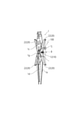
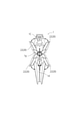
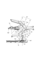
- FIG. 1 is a perspective view of the model toy 1.
- FIG. 2 is a front view of the model toy 1.
- the model toy 1 is a vertically long plate-shaped plastic model structure, for example, which is used by being attached to a robot character 100 (not shown as a whole).
- This is a model that imitates a defensive shield used in character 100.
- This model toy 1 is a toy body including a plate-shaped upper cover portion 1c, a lower cover portion 1d, and both cover portions 1c, 1d on the back side side 1e extending vertically from the center portion 1g in the substantially central portion in the vertical direction. It is equipped with. Further, when the toy body is viewed from the front (see FIG.
- the model toy 1 extends diagonally upward to the left and right and diagonally downward with the center portion 1g as the center, in other words, in an X-shape in all directions.
- a light emitting member 20 including an extension blade portion 22 extending to the surface is provided. Further, although the details of the light emitting member 20 will be described later, the light emitting member 20 is configured to be rotatable around the center portion 1g. It was
- the light emitting member 20 does not have a light source by itself, but has a function of visually emitting the light guided by the light guide member 10 described later from the outside.
- the light is configured to be able to radiate light from both the front and back sides of the extending blade portion 22 of the light emitting member 20.
- a light source 8 such as an LED installed on the robot character 100 side is used. It was
- a detachable mounting locking portion 1j is provided at a predetermined position of the robot character 100 on the back side portion 1e of the toy body. Therefore, as shown in FIG. 1, the light receiving end portion 12t (see FIGS. 4 and 5) of the light guide member 10 faces the light source 8 in a state where the model toy 1 is attached via the mounting locking portion 1j. .. It was
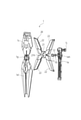
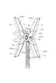
- FIG. 3 is an exploded perspective view of the model toy 1.
- the light emitting member 20 is arranged between the upper cover portion 1c, the lower cover portion 1d, the center portion 1g, and the back side portion 1e.
- the light guide member 10 is held in the holding hole 1eh of the back side portion 1e.
- the light emitting portion 11 on one end side thereof is exposed from the back side portion 1e.
- the light emitting member 20 is held by the back side portion 1e so as to fit the central hole 21h of the annular light entering portion 21 into the light emitting portion 11. That is, in the light emitting member 20, the light entering portion 21 that receives light from the light guide member 10 is held so as to surround the cylindrical light emitting portion 11.
- the light entering unit 21 is rotatably held with respect to the light emitting unit 11. It was
- the structure in which the light emitting portion 21 of the light emitting member 20 surrounds the light emitting portion 11 of the light guide member 10 can increase the facing area between the light emitting portion 11 and the light emitting portion 21, and the light emitting member 20 can be increased from the light emitting member 10. It is convenient to increase the amount of light guide to. Further, since the light guide member 10 is used as the rotation support shaft of the light emitting member 20, it is not necessary to provide the rotation support shaft. It was
- the light emitting member 20 includes a total of four extending blade portions 22 capable of emitting light (a light transmitting material), and is composed of two components overlapping in the thickness direction, as will be described later.
- the light emitting member 20 has a pair of extending blade portions 22 extending in the opposite direction by 180 degrees in the radial direction from the annular light entering portion 21. Then, the two light emitting members 20 are arranged so as to overlap each other in the thickness direction at the light entering portion 21 (see FIG. 6). Therefore, light can be taken in from a plurality of light input units 21, and the light input units 21 can move independently and independently without interlocking with each other. It was
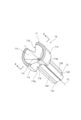
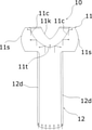
- FIG. 4 is an enlarged perspective view of the light guide member 10.
- FIG. 5 is a cross-sectional arrow view of a portion of the light guide member 10 along the line AA in FIG.
- the light guide member 10 includes a light guide body portion 12 that guides the light of the light source 8 to the light emitting unit 11.
- the light emitting portion 11 is formed to have a larger diameter than the light guide body portion 12.
- the light emitting portion 11 is formed with a recessed surface 11c formed on an end surface opposite to the arrangement side of the light source 8.
- the recessed surface 11c is configured to be recessed in a substantially conical shape, for example.
- the recessed surface 11c is configured as an inverted conical surface when the top portion 11t is located on the light source side and is viewed from the light source 8 side. Therefore, the light incident from the light guide body 12 is reflected toward the arc outer surface 11s. The reflected light of the light source 8 is radiated from the outer surface of the arc 11s toward the incoming light portion 21. It was
- the recessed surface 11c reflects the light from the light source 8 in a predetermined direction because the top portion 11t is located on the arrangement side of the light source 8. Moreover, since the recessed surface 11c has an inverted conical shape, light can be uniformly reflected in any direction of 360 degrees in the direction intersecting the axis CL of the light guide member 10. Further, the inclination angle of the recessed surface 11c is constant (see FIG. 5), and a large amount of parallel light (light convenient for light guide) directed in the extending direction of the light emitting member 20 can be emitted as reflected light.
- the top portion 11t is formed in an arc shape in the figure, it has an extremely small R shape in the actual model toy 1. Therefore, the light of the light source 8 hardly leaks from the top 11t. It was
- a plurality of ridges 12d are formed at equal intervals in the circumferential direction of the outer peripheral surface 12s along the axial core line CL of the light guide body 12. That is, although the light guide body portion 12 is configured to have a small diameter, the ridges 12d substantially increase the rigidity and have a structure in which the strength is increased. It was
- the light guide member 10 has a diameter as large as possible according to the size of the light source 8 because a large amount of light can be guided by increasing the light guide cross-sectional area.
- the resin sink mark during molding becomes large and air bubbles tend to remain in the molded resin, so that the light guide efficiency decreases. It was
- the light guide body portion 12 is substantially thinner than the diameter of the light emitting portion 11 seems to reduce the light guide efficiency at first glance, but it suppresses the generation of air bubbles as well as the resin sinking during molding. On the contrary, it is possible to suppress a decrease in light guide efficiency.
- the intensity is increased as described above and at the same time the light guide cross-sectional area is increased so that more light can be guided. There is.
- the shape of the light guide member 10 is a cylindrical shape having a barrel that matches the diameter of the light emitting portion 11, the light guide efficiency can be improved and the yield can be improved, and high-quality light guide can be obtained.
- the member 10 can be stably manufactured. Further, the light guide cross-sectional area of the light guide body portion 12 can be obtained by the convex strip 12d. It was
- a notch 11k is formed on the arc outer surface 11s, which is the outer peripheral surface of the light emitting portion 11.
- the notch 11k has two notch surfaces 11ks extending in the outward radius from the axis CL side of the light guide member 10. That is, the notch 11k has a substantially V-shape (see FIG. 8) in a plan view when viewed from the axis CL direction, and defines a light guide path E in which light is emitted from the light emitting portion 11. It is cut out in. Further, a pair of notches 11k are provided with the axis core line CL interposed therebetween. The light guide member 10 is locked so as not to rotate by engaging the locking projection 1i of the back side portion 1e with the notch 11k. It was
- FIG. 6 is an enlarged exploded perspective view showing the mounting structure of the light guide member 10 and the light emitting member 20.
- the light guide body 12 of the light guide member 10 is inserted into the holding hole 1eh.
- the notch 11k is fitted to the locking projection 1i and attached.
- the two light emitting members 20 are fitted to the light emitting part 11 so as to overlap the light entering part 21.
- the regulation protrusion 1w is attached to the pair of openings 21w formed as a notch at the edge of the central hole 21h. It was
- FIG. 7 is an exploded perspective view showing an assembled state of the light guide member 10 and the light emitting member 20.
- the light guide member 10 is locked to the locking projection 1i, and is attached so that the light emitting portion 21 of the light emitting member 20 surrounds the light guide member 10. Further, the light emitting member 20 is provided so that the two light receiving portions 21 overlap each other in the thickness direction thereof.
- the light emitting member 20 can rotate the light guide member 10 by inserting the pair of fitting protrusions 1gd (one of which is not shown) of the center portion 1g shown in FIG. 6 into the fixed boss 1ed of the back side portion 1e. Attached to. It was
- both the locking projection 1i and the regulation projection 1w are integrally configured as a projection f that is continuous in a T-shape in a plan view.
- the locking projection 1i that engages with the light guide member 10 locks the light guide member 10 as described above.
- the regulation protrusion 1w received by the opening 21w of the light entering portion 21 is arranged in a so-called idle fit shape having a gap in the circumferential direction of the light entering portion 21 with respect to the opening 21w. Therefore, the regulating protrusion 1w functions as a rotation position regulating member that allows the light emitting member 20 to rotate by the amount of the gap. It was
- FIG. 8 is an enlarged plan view of the mounting portion of the light emitting member 20 as viewed from the axis CL direction of the light guide member 10.
- the light entering portion 21 of the light emitting member 20 is an annular shape surrounding the light emitting portion 11 as described above. E is defined.
- the light guide path E is configured to have a range of a predetermined angle in which the two extending blade portions 22 rotate. Specifically, the range of the light guide path E is determined by the notch surface 11ks of the notch 11k. It was
- the four extending blade portions 22 extending from the light entering portion 21 to the outside of the radius thereof can be located within the range of the light guide path E. Further, in FIG. 8, the positions of the openings 21w of the light entering portion 21 overlapping in the vertical direction of the paper surface are the lower opening 21w (indicated by the dotted line) and the upper opening 21w (indicated by the solid line). Then, as shown in the figure, the opening positions are arranged so as to deviate from each other by a predetermined angle. As a result, the overlapping light receiving portions 21 can move independently by the maximum angle ( ⁇ ) (the state shown in FIG. 8 indicates the state in which the extending blade portion 22 is opened to the maximum). It was
- the structure is such that light is reliably received by the extending blade portion 22.
- the direction of the notch surface 11ks for determining the light guide path E is oriented so as to face the extending direction of the extending blade portion 22.
- the notch 11k defines the light guide path E, as a matter of course, as shown in the drawing, the notch 11k does not guide light other than the light guide path E to the non-light guide region (FIG. 8).
- the left and right regions sandwiched between the upper and lower light guide paths E) are formed.
- the protrusion 1f described above is provided in this non-light guide region.
- the protrusion 1f (locking protrusion 1i and regulation protrusion 1w) is provided in the non-light guide region, the shape thereof can be relatively freely formed, which causes a decrease in light guide efficiency and a light guide failure. There is no such thing. It was
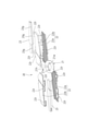
- FIG. 9 is an exploded perspective view of the light emitting member 20.
- the extending blade portion 22 has two overlapping members 22a and 22b that can be divided in the thickness direction thereof.
- the two overlapping members 22a and 22b have, for example, a plurality of engaging pieces 22t projecting from one end side.
- the engaging pieces 22t are arranged so as to be lined up in a row on one end side when the overlapping members 22a and 22b are overlapped. It was
- the overlapping members 22a and 22b are fixed and the extending blade portion 22 is assembled. That is, the extending blade portion 22 is assembled by inserting and fitting the engaging piece 22t into the fixing groove 23g of the blade fixing portion 23.
- the overlapping members 22a and 22b are made of a light-transmitting material, but the blade fixing portion 23 may not be made of a light-transmitting material. It was
- FIG. 10 is a partial cross-sectional view of the light emitting member 20.
- the extending blade portion 22 is provided with a light reflecting portion 22r inside the overlapping members 22a and 22b.
- the light reflecting portion 22r is provided at a middle portion in the thickness direction of the extending blade portion 22.
- the light reflecting portion 22r may have a groove structure (see FIG. 9) extending in a direction intersecting the light path direction, for example.
- the cross-sectional shape of the groove structure is, for example, a substantially triangular unevenness.
- the light reflecting portion 22r is provided inside the superposition members 22a and 22b, the presence of the light reflecting portion 22r gives the appearance of the extending blade portion 22 (reality as a robot character). Does not affect. It was
- the height of the unevenness of the light reflecting portion 22r is configured to be the same over the longitudinal direction of the extending blade portion 22.
- the unevenness on the base side of the extending blade portion 22 can be made small, and the unevenness height of the light reflecting portion 22r can be gradually increased as the unevenness on the base portion side becomes closer to the tip portion side. In this case, not only can the amount of light reaching the tip end side of the extending blade portion 22 be increased, but also it can contribute to uniform light emission in the longitudinal direction of the extending blade portion 22. It was
- FIG. 11 is an enlarged cross-sectional view showing a modified example of the light guide member 10.
- the configuration is provided with the recessed surface 11c and the notch 11k, similar to the configuration shown in FIGS. 4 and 5.
- the concave surface shape of the concave surface 11c may be the above-mentioned inverted conical shape (see FIGS. 4 and 5), but as shown in FIG. 12, a curve having an appropriate curvature so as to bulge toward the arc outer surface 11s. Can be a face.
- the notch 11k can be used as a structure that makes it easy to fix the light guide member 10 as in the above-mentioned configuration. It was
- the radiation direction of the reflected light by the recessed surface 11c can be widened so as to follow the curvature of the arc outer surface 11s.
- the surface shape of the arc inner surface 21s (see FIG. 5) of the light entering portion 21 can be a shape surrounding the arc outer surface 11s, that is, a curved surface formed of a part of a spherical surface that imitates the arc outer surface 11s. ..
- the light entrance unit 21 not only rotates around the light guide body portion 12 along one plane, but also easily swings in the thickness direction of the light input unit 21. It was
- the surface structure of the top portion 11t is configured as a large curved surface or a flat surface.
- a predetermined light can be transmitted at the top 11t. Therefore, the light emitting portion 11 in this case can guide light toward, for example, the center portion 1g other than the extending blade portion 22, and the variety of light effects can be enhanced. It was
- the light guide structure of the model toy 1 of the present embodiment it is possible to provide a light guide structure that allows the light emitting member 20 to rotate with respect to the light guide member 10. Further, since the light entering portion 21 of the light emitting member 20 is provided so as to surround the light emitting portion 11 of the light guide member 10, the facing area between the light emitting portion and the light entering portion can be increased, and the light guiding efficiency is enhanced. The amount of light can be increased. As a result, the light emitting member 20 can produce good light emission even if the light source 8 emits less light. Further, since the light entering unit 21 is rotatably supported by the light emitting unit 11, it is not necessary to have a special support member required for rotation, and the rotating structure can be simplified. As a result, the complicated moving structure of the light emitting member 20 is avoided, and the light guide structure of the model toy 1 having excellent assembleability and manufacturability can be provided. It was
- the light emitting portion 11 has a recessed surface 11c on the end surface opposite to the arrangement side of the light source 8, and the top portion 11t of the recessed surface 11c is on the light source 8 side. Since it is located at, the light of the light source 8 can be reflected in any direction of 360 degrees intersecting the axis CL of the light guide member 10 by the interface formed by the recessed surface 11c. As a result, the light emitting member 20 can be arranged at any position of 360 degrees around the light emitting portion 11, and the movable range of the light emitting member 20 can be set large. It was
- the recessed surface 11c of the light emitting portion 11 has an inverted conical shape, the recessed surface 11c can efficiently reflect light in a certain direction. Moreover, uniform reflection is possible in all directions. Further, since the top portion 11t is formed small in a dot shape, leakage of light from the top portion 11t is avoided, and the light in the light guide body portion 12 can be efficiently reflected. It was
- the light entering portion 21 has an arc inner surface 21s that can always face and move the arc outer surface 11s of the light emitting portion 11, the arc outer surface 11s and the arc outer surface 11s.
- the arc inner surface 21s is rotatable in the arc direction along both inner and outer surfaces 11s and 21s.
- the light emitting member 20 can receive a stable amount of light even if it moves. As a result, the light emitting member 20 can obtain stable light emitting performance even if the light emitting member 20 is rotated so as to draw an arc with respect to the light guide member 10. It was
- the notch 11k is formed on the arc outer surface 11s of the light emitting portion 11, and the locking projection 1i is engaged with the notch 11k.
- the rotation of the light guide member can be fixed. It was
- the notch 11k is formed in a substantially V shape by two notch surfaces 11ks extending from the axial center side of the light guide member so as to follow the direction outside the radius. Therefore, the cutout surface 11 ks can be used as a reflective surface. As a result, the notched surface 11ks functions as a light reflecting surface, and can efficiently guide light in a predetermined direction while avoiding unnecessary diffusion of light. It was
- the light emitting portion 11 is formed to have a larger diameter than the light guide body portion 12, so that even if the light guide body portion 12 is a thin member, light emission is emitted. Since the unit 11 is large, the light input unit 21 can be made large, and it is easy to secure the light input path. Further, since the light emitting unit 11 is large, it is possible to easily provide a plurality of light input units 21. Further, since the light emitting portion 11 is configured to be large, it becomes easy to manufacture the engaging portion between the light emitting portion 11 and the light entering portion 21, and the molding accuracy of the rotating structure between the light emitting portion 11 and the light entering portion 21 can be improved. It was
- the strength of the light guide body 12 can be increased by forming a plurality of ridges 12d on the outer peripheral surface 12s of the light guide body 12. .. Further, the plurality of ridges 12d can increase the cross-sectional area of the light guide and can contribute to substantially increasing the amount of light guide. It was
- the light emitting member 20 includes a light entering portion 21 that can rotate around the light emitting portion 11, and the light entering portion 21 extends outward from the light entering portion radius. Since the plurality of extending blade portions 22 are provided, it is possible to enjoy the light effect accompanied by the movement by the extending blade portions 22 spreading in all directions. It was
- the extending blade portion 22 is provided with a light reflecting portion 22r along the longitudinal direction thereof, so that the extending blade portion 22 extends over the entire length thereof. It can be illuminated on both the front and back sides. Further, since the light reflecting portion 22r is formed in the middle portion of the extending blade portion 22 in the thickness direction, the region closer to the outer surface in the thickness direction functions as a portion where the light easily travels straight, so that the light is spread. It can be guided to the tip side of the protruding blade portion 22. As a result, the extension blade portion 22 can shine well not only to the extension base portion but also to the tip end side, and the light effect can be enhanced. It was
- the extending blade portion 22 is configured by superimposing two overlapping members 22a and 22b in the thickness direction thereof, so that the light reflecting portion 22r is formed. It can be configured to be easy to use. Further, if the unevenness of the light reflecting portion 22r is on the outer surface of the extending blade portion 22, the reality as a robot character may be impaired, but in the present embodiment, it is formed on the inner surface of the extending blade portion 22. Therefore, the light emitting performance can be improved without impairing the appearance of the extending blade portion 22. It was
- the recessed surface 11c of the light emitting portion 11 in the above embodiment is configured as an inverted conical surface, but is not limited to this, and may have various shapes such as a pyramidal surface, a spherical surface, and a polygonal surface. can. It was
- the opening 21w is formed as a notch-shaped opening continuous with the central hole 21h, but the configuration is not limited to this.
- it may be an independent hole-shaped opening that is not continuous with the central hole 21h. It was
- the locking projection 1i and the regulation projection 1w are integrally configured as a part of the projection f of the structure, but the present invention is not limited to this, and a separate independent projection structure may be used. .. It was
- the light reflecting portion 22r is configured as a sawtooth-shaped uneven groove, but in addition, the light reflecting portion 22r may have unevenness such as grain processing.
Landscapes
- Toys (AREA)
Applications Claiming Priority (2)
| Application Number | Priority Date | Filing Date | Title |
|---|---|---|---|
| JP2020128664A JP7261770B2 (ja) | 2020-07-29 | 2020-07-29 | 模型玩具の導光構造 |
| JP2020-128664 | 2020-07-29 |
Publications (1)
| Publication Number | Publication Date |
|---|---|
| WO2022024674A1 true WO2022024674A1 (ja) | 2022-02-03 |
Family
ID=78128299
Family Applications (1)
| Application Number | Title | Priority Date | Filing Date |
|---|---|---|---|
| PCT/JP2021/025214 Ceased WO2022024674A1 (ja) | 2020-07-29 | 2021-07-02 | 模型玩具の導光構造 |
Country Status (3)
| Country | Link |
|---|---|
| JP (2) | JP7261770B2 (enExample) |
| CN (2) | CN116370976A (enExample) |
| WO (1) | WO2022024674A1 (enExample) |
Families Citing this family (2)
| Publication number | Priority date | Publication date | Assignee | Title |
|---|---|---|---|---|
| JP7579931B1 (ja) | 2023-08-04 | 2024-11-08 | 株式会社バンダイ | 模型玩具 |
| JP7743593B1 (ja) * | 2024-12-03 | 2025-09-24 | 株式会社バンダイ | 演出出力玩具 |
Citations (4)
| Publication number | Priority date | Publication date | Assignee | Title |
|---|---|---|---|---|
| JP2003015559A (ja) * | 2001-07-03 | 2003-01-17 | Sega Toys:Kk | 表示装置及び玩具 |
| KR20070082261A (ko) * | 2006-02-15 | 2007-08-21 | 동진전자 주식회사 | 곤충 발광장치 |
| JP2013000133A (ja) * | 2011-06-10 | 2013-01-07 | Bandai Co Ltd | 組み立て人形体 |
| JP2020048925A (ja) * | 2018-09-27 | 2020-04-02 | 株式会社バンダイ | 模型玩具 |
Family Cites Families (9)
| Publication number | Priority date | Publication date | Assignee | Title |
|---|---|---|---|---|
| US4989948A (en) * | 1989-05-08 | 1991-02-05 | Minnesota Mining And Manufacturing Company | Reflective sheeting material |
| US6461216B1 (en) * | 2000-08-31 | 2002-10-08 | John T. Applewhite | Toy device |
| JP3110465U (ja) * | 2005-02-16 | 2005-06-23 | 株式会社アガツマ | 楽器玩具 |
| JP3123274U (ja) * | 2005-12-28 | 2006-07-20 | 有限会社菊地製作所 | リズム玩具 |
| JP5270433B2 (ja) | 2009-04-10 | 2013-08-21 | 日東光学株式会社 | 発光装置および看板用の照明装置 |
| JP2012064558A (ja) | 2010-09-20 | 2012-03-29 | zhi-ming You | 光線を均一に発射させる導光柱及びこの導光柱を応用したledランプ |
| US20120268924A1 (en) * | 2011-04-22 | 2012-10-25 | Lattice Energy Technology Corporation | Light guide unit and optical devices using the same |
| JP5803570B2 (ja) | 2011-10-27 | 2015-11-04 | 日本精機株式会社 | 指針式表示装置 |
| CN204522312U (zh) * | 2015-02-12 | 2015-08-05 | 广东奥飞动漫文化股份有限公司 | 一种趣味拼插的玩具剑 |
-
2020
- 2020-07-29 JP JP2020128664A patent/JP7261770B2/ja active Active
-
2021
- 2021-07-02 WO PCT/JP2021/025214 patent/WO2022024674A1/ja not_active Ceased
- 2021-07-16 CN CN202310245512.3A patent/CN116370976A/zh active Pending
- 2021-07-16 CN CN202110804686.XA patent/CN113521771B/zh active Active
-
2023
- 2023-04-10 JP JP2023063180A patent/JP7601936B2/ja active Active
Patent Citations (4)
| Publication number | Priority date | Publication date | Assignee | Title |
|---|---|---|---|---|
| JP2003015559A (ja) * | 2001-07-03 | 2003-01-17 | Sega Toys:Kk | 表示装置及び玩具 |
| KR20070082261A (ko) * | 2006-02-15 | 2007-08-21 | 동진전자 주식회사 | 곤충 발광장치 |
| JP2013000133A (ja) * | 2011-06-10 | 2013-01-07 | Bandai Co Ltd | 組み立て人形体 |
| JP2020048925A (ja) * | 2018-09-27 | 2020-04-02 | 株式会社バンダイ | 模型玩具 |
Also Published As
| Publication number | Publication date |
|---|---|
| JP7261770B2 (ja) | 2023-04-20 |
| CN113521771A (zh) | 2021-10-22 |
| CN113521771B (zh) | 2023-03-24 |
| CN116370976A (zh) | 2023-07-04 |
| JP7601936B2 (ja) | 2024-12-17 |
| JP2023076745A (ja) | 2023-06-01 |
| JP2022025695A (ja) | 2022-02-10 |
Similar Documents
| Publication | Publication Date | Title |
|---|---|---|
| JP7601936B2 (ja) | 模型玩具の導光構造 | |
| JP4433498B2 (ja) | レンズ | |
| TWI500985B (zh) | 導光裝置 | |
| JP6576719B2 (ja) | 車両用灯具 | |
| JP5789628B2 (ja) | 灯具 | |
| CN102072457A (zh) | 用于光源等等的透镜元件 | |
| CN104534379A (zh) | 机动车灯 | |
| JPH1157124A (ja) | パチンコ機 | |
| JP5931549B2 (ja) | 遊技機 | |
| US20060193147A1 (en) | Light guide and illumination apparatus | |
| JP6268881B2 (ja) | 車両用灯具 | |
| JP2023076745A5 (enExample) | ||
| JP2015088375A (ja) | 灯火器 | |
| US11781734B2 (en) | Lens component and signal display lamp | |
| JP5815355B2 (ja) | 車両用灯具のインナーレンズ | |
| CN110624257B (zh) | 模型玩具 | |
| EP3954942A1 (en) | Vehicle light fixture | |
| JP2018120708A (ja) | 車両用灯具 | |
| JP7277196B2 (ja) | 車両用灯具ユニット及び車両用灯具 | |
| WO2023157585A1 (ja) | 車輌用灯具 | |
| JP6839367B2 (ja) | 車両用発光装置 | |
| JP2005301157A (ja) | 面状発光体 | |
| JP2013131386A (ja) | Led光源用レンズ及びレンズアレイ | |
| JP7277004B2 (ja) | 車両用灯具 | |
| JP2007144023A (ja) | 回転装飾装置及び遊技機 |
Legal Events
| Date | Code | Title | Description |
|---|---|---|---|
| 121 | Ep: the epo has been informed by wipo that ep was designated in this application |
Ref document number: 21848525 Country of ref document: EP Kind code of ref document: A1 |
|
| NENP | Non-entry into the national phase |
Ref country code: DE |
|
| 122 | Ep: pct application non-entry in european phase |
Ref document number: 21848525 Country of ref document: EP Kind code of ref document: A1 |