WO2022024618A1 - 診療支援装置、診療支援装置の作動方法 - Google Patents
診療支援装置、診療支援装置の作動方法 Download PDFInfo
- Publication number
- WO2022024618A1 WO2022024618A1 PCT/JP2021/024043 JP2021024043W WO2022024618A1 WO 2022024618 A1 WO2022024618 A1 WO 2022024618A1 JP 2021024043 W JP2021024043 W JP 2021024043W WO 2022024618 A1 WO2022024618 A1 WO 2022024618A1
- Authority
- WO
- WIPO (PCT)
- Prior art keywords
- medical
- examination
- image
- medical image
- axis
- Prior art date
Links
Images


Classifications
-
- A—HUMAN NECESSITIES
- A61—MEDICAL OR VETERINARY SCIENCE; HYGIENE
- A61B—DIAGNOSIS; SURGERY; IDENTIFICATION
- A61B5/00—Measuring for diagnostic purposes; Identification of persons
-
- G—PHYSICS
- G16—INFORMATION AND COMMUNICATION TECHNOLOGY [ICT] SPECIALLY ADAPTED FOR SPECIFIC APPLICATION FIELDS
- G16H—HEALTHCARE INFORMATICS, i.e. INFORMATION AND COMMUNICATION TECHNOLOGY [ICT] SPECIALLY ADAPTED FOR THE HANDLING OR PROCESSING OF MEDICAL OR HEALTHCARE DATA
- G16H30/00—ICT specially adapted for the handling or processing of medical images
Definitions
- the present invention relates to a medical care support device and a method of operating the medical care support device.
- MRI Magnetic Resonance Imaging
- CT Computer Tomography
- Patent Document 1 displays the relationship between a plurality of medical images obtained by a plurality of examinations for one lesion and the time course of the lesion size of the lesion site included in each medical image. Further, in Patent Document 2 below, a medical image and a site name corresponding to the position of the slide bar are displayed. Further, in the following Patent Document 3, the imaging time of the medical image is displayed on the timeline.
- the imaging time (examination time) of the medical image including each lesion site there was a problem that it was difficult to know the imaging time (examination time) of the medical image including each lesion site.
- the time of taking a medical image (inspection time) including each lesion site may be different, such as being detected only in the previous examination. That is, conventionally, the case where a plurality of lesion sites are detected is not considered, and it is difficult to know the imaging time (examination time) of each medical image including each lesion site.
- the burden on doctors and the like is heavy.
- the present invention has been made in consideration of the above background, and even when a plurality of lesion sites are detected by the examination, it is easy to understand the shooting time (examination time) of the medical image including each lesion site. It is an object of the present invention to provide a medical care support device and a method of operating the medical care support device.
- the medical care support device of the present invention is a medical care support device provided with an image processing processor, in which a medical image obtained by an examination in which the image processing processor images a plurality of parts is stored. From the medical image database, multiple medical images obtained by multiple examinations performed on a common patient at different examination times are acquired, and the examination axis on which the medical images with the same examination time are arranged and the examination.
- a display screen in which medical images are arranged is generated, and an inspection time display area indicating an inspection time in which the medical image displayed in the image display area is captured is provided on the display screen.
- the image display area may have a baseline in which the medical image as a reference of the lesion site is arranged in parallel with the examination axis regardless of the examination time.
- the examination time display area may have a timeline in which an index indicating each of the medical images is arranged at a position corresponding to the examination time of each medical image.
- the examination time display area is a two-dimensional area having a time axis indicating the examination time and a lesion information axis intersecting the time axis and indicating the magnitude of the index value relating to the lesion site.
- the index indicating each of the medical images may be arranged at a position corresponding to the inspection time and the index value of each medical image.
- the index value may be the size of the lesion site.
- the examination time display area may display the examination time and the index value of each medical image in the form of a line graph in which the indexes of medical images having a common lesion site are connected by a line segment.
- the aspect of the line segment may be different for each lesion site.
- the mode of the index may be different for each lesion site.
- the mode of the index may differ depending on the inspection time.
- the index indicating the medical image displayed in the image display area may be highlighted.
- the method of operating the medical care support device of the present invention is the method of operating the medical care support device provided with the image processing processor, in which the image processing processor takes an image of a plurality of parts. From the medical image database in which the obtained medical images are stored, multiple medical images obtained by multiple examinations performed on a common patient at different examination times are acquired, and the medical images having the same examination time are obtained. A two-dimensional image display area having an examination axis in which medical images are arranged, an axis that intersects the examination axis, and an axis in which medical images having a common imaging site are arranged, and a site axis provided for each lesion site detected in the examination. A display screen in which medical images acquired from a medical image database are arranged is generated, and an examination time display area indicating an examination time in which the medical image displayed in the image display area is captured is provided on the display screen.
- a medical treatment support device capable of displaying a medical image in a state suitable for medical treatment, and an operation method of the medical treatment support device.
- the medical care support system 10 is a computer system for managing and using medical information in a medical facility such as a hospital.
- the medical care support system 10 includes a medical care support server 11 (medical care support device), a client terminal 12, a modality 13, and a medical image server 22. These are connected to each other so as to be able to communicate with each other by a network 14 such as a LAN (Local Area Network) laid in the medical facility.
- LAN Local Area Network
- the medical care support server 11 functions as the medical care support device of the present invention. Specifically, the medical care support server 11 acquires the medical image 24 from the medical image database 22A of the medical image server 22 in accordance with the distribution request from the client terminal 12, and uses the acquired medical image 24 to display the screen 15 (FIG. FIG. 4) is generated. Then, the display screen 15 is delivered to the requesting client terminal 12. The display screen 15 is displayed on the display 34 of the client terminal 12.
- the client terminal 12 is installed in each clinical department in a medical facility such as internal medicine, surgery, otolaryngology, and ophthalmology, and is operated by a doctor in each clinical department who is a user.
- the client terminal 12 transmits a display screen distribution request to the medical care support server 11, and displays the display screen 15 distributed from the medical care support server 11 on the display 34 in response to the display screen distribution request. That is, the client terminal 12 functions as a viewer terminal for the doctor to view the display screen 15.
- the medical care support server 11 distributes the display screen 15 to the client terminal 12 in the form of XML data for web distribution created by a markup language such as XML (Extensible Markup Language).
- the client terminal 12 reproduces and displays the display screen 15 on the web browser based on the XML data.
- Modality 13 is an inspection device that obtains a medical image 24 by imaging a plurality of sites (multiple positions of a subject) in one inspection.
- an MRI (Magnetic Resonance Imaging) inspection device or a CT (Computed Tomography) inspection device is used.
- the medical image server 22 is a so-called PACS (Picture Archiving and Communication System) server, and has a medical image database 22A in which the medical image 24 captured by the modality 13 is stored.
- the medical image 24 is, for example, a CT image captured by a CT inspection device and an MRI image captured by an MRI inspection device.
- the medical image 24 is, for example, image data created in a DICOM (Digital Imaging and Communications in Medicine) standard data file format, and can be searched and viewed from a client terminal 12 or the like using ancillary information or the like described later as a keyword. It is possible.
- DICOM Digital Imaging and Communications in Medicine
- Ancillary information is attached to the medical image 24.
- the incidental information is information related to each medical image 24, and is the name, age, and gender of the patient of the subject, the imaging date and time (examination date and time), the imaging conditions, and the imaging site (which part of the patient is the image captured). Information), and image analysis information.
- the image analysis information is information showing the analysis result obtained by analyzing the medical image 24, and includes the presence / absence of a lesion site, position, size (size), type, degree (stage), and the like.
- the analysis of the medical image 24 may be performed by a human such as a doctor or may be performed mechanically by an image processing device or the like.
- the medical image 24 is analyzed mechanically, for example, the medical image is divided into a plurality of small areas, and the image feature amount is calculated from the divided medical images. Then, based on the calculated feature amount, it is determined whether or not each small region is a lesion site, and a group of regions identified as the same type is extracted as one lesion site. Further, the type and / or the degree (stage) of the lesion site is determined based on the feature amount in the lesion site and the mode (position, size (size), shape, etc.) of the lesion site. It is preferable that various judgments in mechanical image processing are made by a machine learning algorithm such as a convolutional neural network or deep learning.
- the medical care support server 11, the client terminal 12, and the medical image server 22 install a control program such as an operating system and an application program such as a server program or a client program based on a computer such as a server computer, a personal computer, or a workstation. It is composed of.
- the computers constituting the medical care support server 11, the client terminal 12, and the like have the same basic configuration, and are the storage device 30, the memory 31, the CPU (Central Processing Unit) 32, and the communication unit, respectively. It includes 33, a display 34, and an input device 35. These are interconnected via the data bus 36.
- the storage device 30 is a hard disk drive built in a computer constituting a medical care support server 11, a client terminal 12, or the like, or a hard disk drive connected via a cable or a network, or a disk array in which a plurality of hard disk drives are connected.
- the storage device 30 stores control programs such as an operating system, various application programs, and display data of various operation screens associated with these programs.
- the memory 31 is a work memory for the CPU 32 to execute a process.
- the CPU 32 comprehensively controls each part of the computer by loading the program stored in the storage device 30 into the memory 31 and executing the processing according to the program.
- the communication unit 33 is a network interface that controls transmission of various information via the network 14.
- the display 34 displays various operation screens according to the operation of the input device 35 such as a mouse and a keyboard.
- the operation screen is equipped with an operation function by GUI (Graphical User Interface).
- GUI Graphic User Interface
- the computer constituting the medical care support server 11, the client terminal 12, and the like accepts the input of the operation instruction from the input device 35 through the operation screen.
- browsing software for browsing the display screen 15 is installed in the client terminal 12, and in the client terminal 12, the CPU 32 cooperates with the memory 31 when the browsing software is started. Then, it functions as a GUI control unit 40 and a request issuing unit 41.
- display screen generation software for generating the display screen 15 is installed in the medical care support server 11, and in the medical care support server 11, the CPU 32 cooperates with the memory 31 when the display screen generation software is started. It works to configure the image processing processor of the present invention and functions as a display screen generation unit 42.
- the GUI control unit 40 controls the screen to be displayed on the display 34 in response to an operation instruction input from the input device 35 of the client terminal 12 through a button click operation or the like by the cursor 43.
- the request issuing unit 41 issues various requests according to the operation instructions made via the GUI control unit 40, and transmits them to the medical care support server 11.
- Various requests include a delivery request for the display screen 15 and a display switching request for designating and changing the medical image 24 to be displayed on the display screen 15.
- the display screen generation unit 42 receives a distribution request from the client terminal 12, generates a display screen 15, and distributes it to the client terminal 12.
- the distributed display screen 15 is displayed on the display 34 of the client terminal 12 via the GUI control unit 40.
- the display screen generation unit 42 receives the display switching request and changes the display content of the display screen 15 (display switching). Specifically, a new display screen 15 whose display contents are changed in response to a display switching request is generated and distributed. Then, the new display screen 15 is displayed on the display 34 of the client terminal 12, so that the display content is changed. In this way, in the medical care support system 10, the display screen 15 can be displayed and the display contents can be changed by operating the client terminal 12.
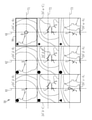
- the display screen 15 includes a medical image display area 50, an examination time display area 52, 54, a bird's-eye view image display area 56, and a pre-enlargement image display area 58.
- the display screen 15 is for observing the lesion site and its temporal change, etc. for a common patient, and allows the patient to be observed (the patient of the subject of the medical image 24 displayed on the display screen 15) to be observed through the client terminal 12. It is generated by the display screen generation unit 42 by designating and transmitting a delivery request to the medical care support server 11.
- the medical image display area 50 is a two-dimensional area in which the medical image 24 is arranged, and intersects the inspection axes 61 and 62 and the inspection axes 61 and 62 (vertical in the present embodiment). (Crossing) site axes 71, 72, 73. Further, the medical image display area 50 includes a baseline 81 parallel to the inspection axes 61 and 62. The inspection axes 61, 62, the site axes 71, 72, 73, and the baseline 81 are all virtual line segments (axises, lines) that are not displayed on the display screen 15 (cannot be visually recognized by the user).
- Medical images 24 having a common inspection time are arranged on the inspection axes 61 and 62. Then, on the inspection axis 61, the medical images 24 obtained in the latest inspection (current inspection) are arranged. That is, the inspection shaft 61 corresponds to the current inspection shaft of the present invention (hereinafter, the inspection shaft 61 may be referred to as the current inspection shaft 61). Further, on the inspection axis 62, the medical images 24 obtained in the inspection prior to the latest inspection (in the present embodiment, the inspection immediately before the latest inspection (previous inspection)) are arranged. That is, the inspection axis 62 corresponds to the past inspection axis of the present invention (hereinafter, the inspection axis 62 may be referred to as a past inspection axis 62).
- the inspection axis may be only the current inspection axis 61 (the past inspection axis 62 may be abolished). Further, a plurality of past inspection shafts 62 may be provided so that the medical images 24 obtained in the past inspection (for example, the inspection two times before the previous inspection) may be arranged.
- Medical images 24 having a common imaging site are arranged on the site axes 71, 72, and 73. These site axes 71, 72, 73 are provided for each lesion site. Specifically, a site axis is provided for an imaging site including a lesion site detected by a past and / or present (most recent) examination among all imaging sites. In other words, a site axis is not provided for an imaging site for which there is no detection history of the lesion site. That is, FIG. 5 shows an example in which three lesion sites A to C were detected in past and / or present examinations.
- the importance of the lesion sites A to C is determined, and the lesion sites A, B, and C (including the lesion sites of each of the lesion sites A, B, and C) are included based on the determination result.
- the arrangement order of the medical image 24) (which of the site axes 71, 72, and 73 is arranged) is determined.
- the lesion site B determined to have the highest importance is arranged on the upper site axis 71, and the lesion determined to have the second highest importance.
- the site C is arranged on the middle site axis 72, and the lesion site A determined to be the least important is arranged on the lower site axis 73.
- the treatment history can be acquired by the display screen generation unit 42 by accessing an electronic medical record database (not shown) in which the electronic medical record is stored.
- the procedure for generating the medical image display area 50 will be described more specifically with reference to FIGS. 5 to 7.
- the display screen generation unit 42 accesses the medical image database 22A to access the lesion site (in the medical image 24 of the patient to be observed).
- a medical image 24 of the site where the lesion site A, B, C) is detected is acquired.
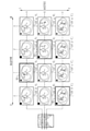
- FIG. 6 shows an example of the medical image 24 acquired in this way. Specifically, in FIG. 6, inspections are performed at each of the four inspection periods of inspection time ⁇ , inspection time ⁇ , inspection time ⁇ , and inspection time ⁇ , in order from the newest inspection time, and these inspections are performed. In the case where the lesion site A, the lesion site B, and the lesion site C are detected in the patient's lung in order from the upper side (head side), the medical image 24 acquired from the medical image database 22A in such a case. Shows a list of.
- the medical image 24 including the lesion site A acquired in the examination at the examination time ⁇ is the medical image 24 “ ⁇ -A”, and the lesion acquired in the examination at the examination time ⁇ .
- the medical image 24 including the site C will be described by distinguishing the medical image 24 according to the examination time and the imaging site (which lesion site is included), such as the medical image 24 “ ⁇ -C”.
- each lesion site in this embodiment, the lesion sites A to C
- the outline of each lesion site is drawn as a thick line.
- each lesion site is highlighted (highlighted).
- the mode of emphasizing the lesion site is not limited to the above-mentioned example.
- the lesion site may be emphasized by surrounding the lesion site with a frame, making the display color different from the surroundings, blinking the display, or the like.
- the star-shaped index “ ⁇ ” is set for the medical image 24 “ ⁇ -A to C” captured at the inspection time ⁇ at the inspection time ⁇ .
- a circular index “ ⁇ ” is used for the captured medical images 24 " ⁇ -A to C”
- a triangular index “ ⁇ ” is used for the medical images 24 " ⁇ -A to C” captured at the examination time ⁇ .
- the mode of the index may be changed for each lesion site.
- the mode of the index is the shape, size, color of the index, and one or a combination of these.
- the mode of the index may be changed so that both the examination time and the lesion site can be distinguished.
- the difference in the examination time is indicated by the difference in the shape of the index
- the difference in the lesion site is indicated by the difference in the color of the index.
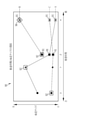
- FIG. 7 shows a line graph 90 showing the relationship between the examination time and the lesion size of each of the lesion sites A to C.
- the line graph 90 is generated by the display screen generation unit 42 using the image analysis information of the medical image 24 (see FIG. 6) acquired from the medical image database 22A, and is displayed in the inspection time display area 52 described later. It is similar to what you do (see Figure 4).
- the above-mentioned inspection time is shown in a two-dimensional region in which the horizontal axis is the time axis indicating the inspection time and the vertical axis is the lesion information axis indicating the index value (in this embodiment, the lesion size) relating to the lesion site.
- Indicators that is, a star-shaped index " ⁇ " indicating that the inspection time is ⁇ , a circular index “ ⁇ ” indicating that the inspection time is ⁇ , and a triangular index " ⁇ ” indicating that the inspection time is ⁇ , By arranging a square index " ⁇ " indicating that the examination time is ⁇ and connecting them with a line segment, the relationship between the examination time and the lesion size is shown.
- the type of line segment (line segment) connecting the indicators indicating the inspection time is "broken line” for lesion site A, "dashed line” for lesion site B, and "two-dot chain line” for lesion site C.
- chain line that is, by making the line segment of the line segment connecting the indexes different for each lesion site, which of the lesion sites A to C shows the change in the lesion size. It is identifiable.
- the mode of the line segment other than the line segment for example, the color of the line segment may be different for each lesion site.
- the index mode may be different for each lesion site.
- the lesion site A was detected for the first time on the medical image 24 “ ⁇ -A”, and an increase in size was detected on the subsequent medical image 24 “ ⁇ -A”.
- Treatment is performed between the time of examination and ⁇ , and the reduction is detected in the medical image 24 “ ⁇ -A” after the treatment, and the reduced state is maintained in the subsequent medical image 24 “ ⁇ -A”.
- An example is shown in which it is detected that (there is almost no size change).
- the lesion site B was not detected in the medical image 24 " ⁇ -B” and the medical image 24 " ⁇ -B", but was detected for the first time in the medical image 24 " ⁇ -B", and then the medical image 24 " ⁇ -".
- "B” shows an example in which an increase in size is detected.
- the lesion site C is detected for the first time on the medical image 24 " ⁇ -C", and any of the subsequent medical image 24 " ⁇ -C", the medical image 24 " ⁇ -C” and the medical image 24 " ⁇ -C".
- it shows an example in which it was detected that the size did not change much from the initial state.
- the display screen generation unit 42 uses the medical image 24 as a reference for each lesion site, that is, the above-mentioned.
- the medical image 24 to be arranged on the baseline 81 (see FIG. 5) is determined.
- the lesion site A is treated. Therefore, for the lesion site A, the medical image 24 “ ⁇ -A” of the straight line of treatment is determined as a reference. On the other hand, the lesion sites B and C have not been treated. Therefore, for the lesion site B, the medical image 24 “ ⁇ -B” in which the lesion site B is detected for the first time is displayed, and for the lesion site C, the medical image 24 “ ⁇ -C” in which the lesion site C is detected for the first time is displayed. , Each is determined as a standard.
- the index indicating that it is the medical image 24 (medical image 24 arranged in the baseline 81) thus determined or the medical image 24 arranged in the baseline 81 is shown. It is highlighted by surrounding it with a rectangular frame 92. By doing so, it is easy to grasp the imaging time (examination time) of the medical images 24 arranged in the baseline 81. In particular, since the medical images arranged in the baseline 81 are determined regardless of the examination time, there are cases where the examination time is different. Therefore, by highlighting as described above, the effect that the inspection time can be easily grasped becomes remarkable.
- the display screen generation unit 42 determines the importance of the lesion site.
- the importance of the lesion site indicates the priority in the case of treatment such as treatment and / or follow-up, and in the present embodiment, the larger the growth rate of the lesion site, the higher the importance. Is determined.
- the growth rate of the lesion site is determined by comparing the lesion size between the medical image 24 captured in the latest examination (examination at the examination time ⁇ ) and the medical image 24 arranged at the baseline 81. It is calculated. In the present embodiment, the growth rate is higher in the order of lesion site B, lesion site C, and lesion site A (see FIG. 7). Therefore, in the present embodiment, it is determined that the importance is higher in the order of lesion site B, lesion site C, and lesion site A.
- the growth rate is calculated by comparing the latest examination with the baseline 81 (the examination in which the medical image 24 arranged in the baseline 81 is captured), but the lesion is the first lesion with the latest examination.
- the rate of increase may be calculated by comparison with the test in which the site was detected.
- the rate of increase may be calculated by comparing the latest test with the test performed immediately before the latest test.
- the importance may be determined using the type and degree (stage) of the lesion.
- the importance may be determined in consideration of a plurality of factors from the growth rate, the type of lesion, the degree (stage), and the like.
- a user such as a doctor may operate the client terminal 12 to specify the importance.
- the display screen generation unit 42 When the importance of the lesion site is determined, the display screen generation unit 42 generates the medical image display area 50 using the determined importance. Specifically, as shown in FIG. 5, the more important the lesion site is, the more important the medical images 24 “ ⁇ -A to C” obtained in the examination at the examination time ⁇ , which is the latest examination (current examination). Currently arranged on the inspection axis 61 so as to be located in the upper row. More specifically, the medical image 24 " ⁇ -B" is attached to the portion where the current inspection axis 61 and the site axis 71 intersect, and the medical image 24 " ⁇ -B” is attached to the portion where the current inspection axis 61 and the site axis 72 intersect. The medical image 24 " ⁇ -A” is arranged at the portion where the inspection axis 61 and the site axis 73 currently intersect with each other.
- the medical images 24 " ⁇ -A to C" obtained in the examination at the examination time ⁇ which is the examination immediately before the latest examination (previous examination), are located in the upper row as the importance of the lesion site increases.
- they are arranged on the past inspection axis 62. More specifically, the medical image 24 " ⁇ -B” is attached to the portion where the past inspection axis 62 and the site axis 71 intersect, and the medical image 24 " ⁇ -B” is attached to the portion where the past inspection axis 62 and the site axis 72 intersect.
- the medical image 24 " ⁇ -A” is arranged at the portion where the past examination axis 62 and the site axis 73 intersect with each other.
- the medical images 24 " ⁇ -A”, 24 “ ⁇ -B”, and 24 “ ⁇ -C”, which are the reference of the lesion sites A to C, are located in the upper row as the importance of the lesion site increases.
- the medical image 24 " ⁇ -A” is arranged at the portion where the baseline 81 and the site axis 73 intersect with each other.
- the display screen generation unit 42 enlarges each of the medical images 24 arranged in the medical image display area 50 so as to be easy to observe, so that the lesion site is located at the center of the enlarged image (common to the images). Align the enlarged image so that the common part is displayed at the position of). It is preferable that the medical images 24 arranged on the common site axis have a common scale (scale) (the enlargement ratio is adjusted so as to be a common scale). Further, it is preferable that the medical images 24 arranged on the common site axis are displayed with a common contrast (the contrast is adjusted so as to have a common contrast). By aligning the scale and / or the contrast in this way, the comparison of lesion sites can be smoothly performed. Of course, not only the medical images 24 arranged on the common site axis, but also all the medical images 24 arranged in the medical image display area 50 may have the same scale and / or contrast.
- the medical image display area 50 generated in this way by observing the medical images 24 currently arranged on the examination axis 61, the medical images 24 for each lesion site currently imaged in the examination can be observed, which is convenient. be. Further, by observing the medical image 24 arranged on the current inspection axis 61 and the medical image 24 arranged on the past inspection axis 62, the medical image 24 captured in the current inspection and the medical image captured in the previous inspection are observed. It is convenient because it is possible to compare with 24 for each lesion site. Further, by observing the medical image 24 currently arranged on the examination axis 61 and the medical image 24 arranged on the baseline 81, the medical image 24 currently captured in the examination and the medical image 24 as a reference of the lesion site 24 are observed. It is convenient because you can compare and for each lesion site.
- the line graph 90 shown in FIG. 7 is displayed in the inspection time display area 52.
- the line graph 90 shows the relationship between the examination time (imaging time) of the lesion sites A to C and the lesion size, and the inspection of the lesion sites A to C is performed by viewing the line graph 90. It is convenient to understand the relationship between the time and lesion size.
- the index indicating the medical image 24 displayed in the medical image display area 50 is emphasized by being surrounded by a frame 91. As a result, it is possible to grasp which of all the medical images 24 including the lesion sites A to C (among the medical images 24 whose indicators are displayed in the line graph 90, which medical image 24 is displayed in the medical image display area 50). It's possible and convenient.
- the index showing the medical image 24 arranged in the baseline 81 is surrounded by a frame 92 which is one size larger than the above-mentioned frame 91 and emphasized. This is convenient because it is possible to grasp the time when the medical image 24, which is the reference of each lesion site, was taken.
- the medical image 24 selected by operating the client terminal 12 or the like (on the upper right side of the medical image display area 50 in FIG. 4).
- the medical image 24) is emphasized by surrounding it with a frame 94 (see FIGS. 4 and 5).
- an index indicating the examination time in which the medical image 24 (the selected medical image 24 and the medical image 24 surrounded by the frame 94 in the medical image display area 50) is captured is displayed. It is emphasized by surrounding it with a frame 96 (see FIGS. 4 and 7). By doing so, it is easy and convenient to grasp the examination time and the lesion size of the selected medical image 24.
- the relationship between the test time and the lesion size is displayed in the test time display area 52, but the relationship between the test time and the index value related to the lesion site is displayed in the test time display area 52. It suffices if it has been done. That is, in the present embodiment, the example in which the “index value regarding the lesion site” is the “lesion size” has been described, but the present invention is not limited to this.
- the index value for the lesion site may be other than the lesion size, such as the growth rate and degree (stage) of the lesion site.
- the relationship between the inspection time and the index value related to the lesion site has been described with an example of displaying the relationship between the inspection time and the lesion site in the form of a “line graph”. The relationship may be displayed in a form other than the line graph.
- the timeline 100 shown in FIG. 8 is displayed in the inspection time display area 54.
- a star-shaped index “ ⁇ ” indicating the inspection time ⁇ a circular index “ ⁇ ” indicating the inspection time ⁇
- a triangular index “ ⁇ ” indicating the inspection time ⁇ a triangular index indicating the inspection time ⁇
- a quadrangular index indicating the inspection time ⁇ The index " ⁇ ” is arranged, and the inspection time can be grasped by observing the timeline 100.
- an index 102 is provided at the time of the examination in which the medical images 24 arranged in the baseline 81 are captured. As a result, it is possible to grasp the time of the imaged examination of the medical images 24 arranged in the baseline 81.
- the timeline 100 is provided with an index 104 at the time of the imaged examination of the medical image 24 (medical image 24 surrounded by the frame 94 in FIGS. 4 and 5) selected in the medical image display area 50. There is. This makes it possible to grasp the imaging timing of the selected medical image 24.
- the example in which the two inspection time display areas 52 and 54 are provided has been described, but one of them may be abolished.
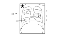
- the bird's-eye view image 110 shown in FIG. 9 is displayed in the bird's-eye view image display area 56.
- the bird's-eye view image 110 is for taking a bird's-eye view of the lesion site included in the medical image 24 arranged in the medical image display area 50.
- an image obtained by capturing an image in which all lesion sites are contained for example, an X-ray image of a patient's lung
- a schema diagram human body schematic diagram
- the lesion site B included in the medical image 24 (medical image 24 surrounded by the frame 94 in FIGS. 4 and 5) selected in the medical image display area 50 is surrounded by the frame 114 and emphasized. is doing. As a result, the position of the lesion site included in the selected medical image 24 can be grasped.
- an example in which an image obtained by observing (imaging) a human body in a standing posture from a horizontal direction is used as a bird's-eye view image has been described, but the present invention is not limited thereto.
- the bird's-eye view image an image obtained by observing (imaging) a human body in an upright posture from a vertical direction may be used.
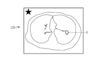
- the pre-enlargement image 120 shown in FIG. 10 is displayed in the pre-enlargement image display area 58.
- the pre-enlargement image 120 is a medical image 24 selected in the medical image display area 50 (medical image 24 surrounded by a frame 94 in FIGS. 4 and 5).
- the pre-enlargement image 120 is not enlarged.
- the peripheral portion of the image that is not displayed in the medical image 24 (selected medical image 24) of the medical image display area 50 can be confirmed, and the position of the lesion site in the entire image can be confirmed. Can be confirmed.
- the hardware-like structure of the processing unit that executes various processes such as the GUI control unit 40, the request issuing unit 41, and the display screen generation unit 42 has various processors as shown below.
- the circuit configuration is changed after manufacturing the CPU (Central Processing Unit), FPGA (Field Programmable Gate Array), etc., which are general-purpose processors that execute software (programs) and function as various processing units. It includes a programmable logic device (PLD), which is a possible processor, a dedicated electric circuit, which is a processor having a circuit configuration specially designed for executing various processes, and the like.
- PLD programmable logic device
- One processing unit may be composed of one of these various processors, or may be composed of a combination of two or more processors of the same type or different types (for example, a plurality of FPGAs or a combination of a CPU and an FPGA). May be done. Further, a plurality of processing units may be configured by one processor. As an example of configuring a plurality of processing units with one processor, first, as represented by a computer such as a client or a server, one processor is configured by a combination of one or more CPUs and software. There is a form in which this processor functions as a plurality of processing units.
- SoC System On Chip
- the various processing units are configured by using one or more of the above-mentioned various processors as a hardware-like structure.
- the hardware-like structure of these various processors is, more specifically, an electric circuit (circuitry) in which circuit elements such as semiconductor elements are combined.
- the hardware structure of the storage unit is a storage device such as an HDD (hard disk drive) or SSD (solid state drive). From the above description, the electronic album device described in the following supplementary items can be grasped.
- a medical care support device equipped with an image processing processor
- the image processing processor In response to a request from the user to output a medical image display screen that captures multiple parts From the medical image database that stores the medical images obtained in the examinations that image multiple sites, multiple medical images obtained in multiple examinations performed on a common patient at different examination times are acquired. death, An examination axis in which medical images having a common examination time are arranged, and an axis in which medical images intersecting with the examination axis and having a common imaging site are arranged, and a site axis provided for each lesion site detected in the examination.
- a display screen in which medical images acquired from the medical image database are arranged is generated in a two-dimensional image display area having.
- An examination time display area indicating the examination time at which the medical image displayed in the image display area is captured is provided on the display screen.
- a medical care support device that outputs the display screen to the user.
- Medical care support system 11 Medical care support server (medical care support device) 12 Client terminal 13 Modality 14 Network 15 Display screen 22 Medical image server 22A Medical image database 24 Medical image 30 Storage device 31 Memory 32 CPU 33 Communication unit 34 Display 35 Input device 36 Data bus 40 GUI control unit 41 Request issuing unit 42 Display screen generation unit 43 Cursor 50 Medical image display area 52, 54 Inspection time display area 56 Overhead image display area 58 Pre-enlargement image display area 61 Inspection axis (current inspection axis) 62 Inspection axis (past inspection axis) 71, 72, 73 Site axis 81 Baseline A, B, C Lesion site 90 Line graph 91 Frame (frame indicating that the image is a medical image displayed in the medical image display area) 92 frames (a frame surrounding a medical image arranged in a baseline or an index indicating that there is a medical image arranged in a baseline) 94, 96 frames (frames surrounding the selected medical image or the index indicating that it is the selected medical image) 100 Timeline 102 Index (Indicator indicating
Abstract
医用画像の撮影時期(検査時期)が判り易い診療支援装置、診療支援装置の作動方法を提供する。診療支援サーバは、医用画像データベースから検査時期の異なる複数回の検査で得られた複数の医用画像を取得し、検査時期が共通する医用画像が並べられる検査軸と、検査軸と交差し、撮像部位が共通する医用画像が並べられる軸であり、検査で検出された病変部位毎に設けられる部位軸と、を有する医用画像表示領域(50)に、医用画像を配列した表示画面(15)を生成する。表示画面(15)は、医用画像表示領域(50)に配列された医用画像の検査時期を示す検査時期表示領域(52、54)を有する。
Description
本発明は、診療支援装置、診療支援装置の作動方法に関する。
MRI(Magnetic Resonance Imaging;核磁気共鳴画像法)検査やCT(Computed Tomography;コンピュータ断層撮像)検査では、1回の検査で患者の複数の部位を撮像して多くの医用画像が得られる。医療施設では、このようにして得られた医用画像を用いて診療が行われる。
診療では、例えば、共通の病変部位を含む検査時期の異なる医用画像を時系列に並べるなどして、病変サイズ等の経時変化が調べられる。下記特許文献1では、1つの病変部について、複数回の検査で得られた複数の医用画像と、各医用画像に含まれる病変部位の病変サイズの経時変化との関係を表示している。また、下記特許文献2では、スライドバーの位置に対応する医用画像と部位名とを表示している。さらに、下記特許文献3では、タイムライン上に医用画像の撮像時期を表示している。
しかしながら、従来は、検査で複数の病変部位が検出された場合に、それぞれの病変部位を含む医用画像の撮像時期(検査時期)が判り難いといった問題があった。つまり、複数の病変部位が検出されると、それぞれの病変部位の経時変化を調べる必要があるが、病変部位によっては、前々回及び前回の検査では検出されなかったが今回の検査では検出された、または、前回の検査でのみ検出されたなど、各病変部位を含む医用画像の撮影時期(検査時期)が異なる場合がある。すなわち、従来は、このように複数の病変部位が検出された場合については考慮されておらず、各病変部位を含む医用画像のそれぞれの撮像時期(検査時期)が判り難かった。また、扱う医用画像の数が膨大な数となるため、医師等の負荷が大きかった。
本発明は、上記背景を考慮してなされたものであり、検査で複数の病変部位が検出された場合であっても、それぞれの病変部位を含む医用画像の撮影時期(検査時期)が判り易い診療支援装置、及び、診療支援装置の作動方法を提供することを目的としている。
上記目的を達成するために、本発明の診療支援装置は、画像処理用プロセッサを備えた診療支援装置において、画像処理用プロセッサが、複数の部位を撮像する検査で得られた医用画像が格納された医用画像データベースから、共通の患者に対して行われた検査時期の異なる複数回の検査で得られた複数の医用画像を取得し、検査時期が共通する医用画像が並べられる検査軸と、検査軸と交差し、撮像部位が共通する医用画像が並べられる軸であり、検査で検出された病変部位毎に設けられる部位軸と、を有する2次元の画像表示領域に、医用画像データベースから取得した医用画像を配列した表示画面を生成し、画像表示領域に表示された医用画像が撮像された検査時期を示す検査時期表示領域を、表示画面に設ける。
画像表示領域は、病変部位の基準となる医用画像が、検査時期に関わらずに検査軸と平行に並べられたベースラインを有していてもよい。
検査時期表示領域は、医用画像の各々を示す指標が、各々の医用画像の検査時期に応じた位置に配されるタイムラインを有していてもよい。
検査時期表示領域は、検査時期を示す時間軸と、時間軸と交差し、病変部位に関する指標値の大きさを示す病変情報軸と、を有する2次元の領域であり、検査時期表示領域には、医用画像の各々を示す指標が、各々の医用画像の検査時期と指標値とに応じた位置に配されるものでもよい。
指標値は、病変部位のサイズであってもよい。
検査時期表示領域は、病変部位が共通する医用画像の指標を線分で繋いだ折れ線グラフの形態で各々の医用画像の検査時期と指標値とを表示するものでもよい。
線分の態様は、病変部位毎に異なっていてもよい。
指標の態様は、病変部位毎に異なっていてもよい。
指標の態様は、検査時期毎に異なっていてもよい。
検査時期表示領域に表示された指標のうち、画像表示領域に表示されている医用画像を示す指標を強調表示してもよい。
また、上記目的を達成するために、本発明の診療支援装置の作動方法は、画像処理用プロセッサを備えた診療支援装置の作動方法において、画像処理用プロセッサが、複数の部位を撮像する検査で得られた医用画像が格納された医用画像データベースから、共通の患者に対して行われた検査時期の異なる複数回の検査で得られた複数の医用画像を取得し、検査時期が共通する医用画像が並べられる検査軸と、検査軸と交差し、撮像部位が共通する医用画像が並べられる軸であり、検査で検出された病変部位毎に設けられる部位軸と、を有する2次元の画像表示領域に、医用画像データベースから取得した医用画像を配列した表示画面を生成し、画像表示領域に表示された医用画像が撮像された検査時期を示す検査時期表示領域を、表示画面に設ける。
本発明によれば、医用画像を診療に適した状態で表示可能な診療支援装置、及び、診療支援装置の作動方法を提供できる。
図1において、診療支援システム10は、病院等の医療施設で医療情報を管理および利用するためのコンピュータシステムである。診療支援システム10は、診療支援サーバ11(診療支援装置)と、クライアント端末12と、モダリティ13と、医用画像サーバ22と、を備えている。これらは医療施設内に敷設されたLAN(Local Area Network)等のネットワーク14で相互に通信可能に接続されている。
診療支援サーバ11は、本発明の診療支援装置として機能する。具体的には、診療支援サーバ11は、クライアント端末12からの配信要求に従って、医用画像サーバ22の医用画像データベース22Aから医用画像24を取得し、取得した医用画像24を用いて表示画面15(図4参照)を生成する。そして、要求元のクライアント端末12に対して表示画面15を配信する。表示画面15は、クライアント端末12のディスプレイ34に表示される。
クライアント端末12は、内科、外科、耳鼻科、眼科といった医療施設内の各診療科に設置され、ユーザである各診療科の医師により操作される。クライアント端末12は、表示画面の配信要求を診療支援サーバ11に送信し、表示画面の配信要求に応じて診療支援サーバ11から配信された表示画面15をディスプレイ34に表示する。つまり、クライアント端末12は、表示画面15を医師が閲覧するためのビューア端末として機能する。
診療支援サーバ11は、表示画面15を、例えば、XML(Extensible Markup Language)等のマークアップ言語によって作成されるウェブ配信用のXMLデータの形式でクライアント端末12に配信する。クライアント端末12は、XMLデータに基づき表示画面15をウェブブラウザ上に再現して表示する。
モダリティ13は、1回の検査で複数の部位(被検体の複数の位置)を撮像して医用画像24を得る検査装置である。モダリティ13としては、例えば、MRI(Magnetic Resonance Imaging;核磁気共鳴画像法)検査装置やCT(Computed Tomography;コンピュータ断層撮像)検査装置が用いられる。
医用画像サーバ22は、いわゆるPACS(Picture Archiving and Communication System)サーバであり、モダリティ13で撮像された医用画像24が格納される医用画像データベース22Aを有する。医用画像24は、例えば、CT検査装置で撮像されたCT画像、MRI検査装置で撮像されたMRI画像である。医用画像24は、例えば、DICOM(Digital Imaging and Communications in Medicine)規格のデータファイル形式で作成された画像データであり、クライアント端末12などから後述する付帯情報等をキーワードとした検索、及び、閲覧が可能である。
医用画像24には、付帯情報が付帯される。付帯情報は、それぞれの医用画像24に関する情報であり、被写体の患者の氏名、年齢、性別、及び、撮像日時(検査日時)、撮像条件、撮像部位(患者のどの部位を撮像した画像であるかを示す情報)、並びに、画像解析情報などである。画像解析情報は、医用画像24を解析することにより得られた解析結果を示す情報であり、病変部位の有無、位置、大きさ(サイズ)、種類、程度(ステージ)などである。
なお、医用画像24の解析は、医師等の人間により行われたものでもよいし、画像処理装置等により機械的に行われたものでもよい。医用画像24の解析を機械的に行なう場合、例えば、医用画像を複数の小領域に分割し、分割した医用画像から画像的な特徴量を算出する。そして、算出した特徴量に基づき、各小領域が病変部位であるか否かを判断し、同じ種類と特定されたひとかたまりの領域を1つの病変部位として抽出する。また、病変部位内の特徴量と、病変部位の態様(位置、大きさ(サイズ)、形状など)と、に基づいて病変部位の種類及び/または病変の程度(ステージ)を判断する。機械的な画像処理における各種の判断は、畳み込みニューラルネットワーク(Convolutional Neural Network)や、深層学習(Deep Learning)などの機械学習アルゴリズムによって行われることが好ましい。
診療支援サーバ11、クライアント端末12、および医用画像サーバ22は、サーバコンピュータ、パーソナルコンピュータ、ワークステーションといったコンピュータをベースに、オペレーティングシステム等の制御プログラムや、サーバプログラムまたはクライアントプログラム等のアプリケーションプログラムをインストールして構成される。
図2に示すように、診療支援サーバ11やクライアント端末12等を構成するコンピュータは、基本的な構成は同じであり、それぞれ、ストレージデバイス30、メモリ31、CPU(Central Processing Unit)32、通信部33、ディスプレイ34、および入力デバイス35を備えている。これらはデータバス36を介して相互接続されている。
ストレージデバイス30は、診療支援サーバ11やクライアント端末12等を構成するコンピュータに内蔵、またはケーブルやネットワークを通じて接続されたハードディスクドライブ、もしくはハードディスクドライブを複数台連装したディスクアレイである。ストレージデバイス30には、オペレーティングシステム等の制御プログラムや各種アプリケーションプログラム、およびこれらのプログラムに付随する各種操作画面の表示データが記憶されている。
メモリ31は、CPU32が処理を実行するためのワークメモリである。CPU32は、ストレージデバイス30に記憶されたプログラムをメモリ31へロードして、プログラムにしたがった処理を実行することにより、コンピュータの各部を統括的に制御する。
通信部33は、ネットワーク14を介した各種情報の伝送制御を行うネットワークインターフェースである。ディスプレイ34は、マウスやキーボード等の入力デバイス35の操作に応じた各種操作画面を表示する。操作画面にはGUI(Graphical User Interface)による操作機能が備えられる。診療支援サーバ11やクライアント端末12等を構成するコンピュータは、操作画面を通じて入力デバイス35からの操作指示の入力を受け付ける。
図3に示すように、クライアント端末12には、表示画面15を閲覧するための閲覧ソフトウエアがインストールされており、クライアント端末12では、閲覧ソフトウエアの起動に伴い、CPU32がメモリ31と協働して、GUI制御部40及び要求発行部41として機能する。また、診療支援サーバ11には、表示画面15を生成するための表示画面生成ソフトウエアがインストールされており、診療支援サーバ11では、表示画面生成ソフトウエアの起動に伴い、CPU32がメモリ31と協働して本発明の画像処理用プロセッサを構成し、表示画面生成部42として機能する。
GUI制御部40は、カーソル43によるボタンのクリック操作等を通じてクライアント端末12の入力デバイス35から入力される操作指示に応じて、ディスプレイ34に表示する画面の制御を行う。要求発行部41は、GUI制御部40を介して行われた操作指示に応じた各種要求を発行し、診療支援サーバ11に対して送信する。各種要求には、表示画面15の配信要求、及び表示画面15に表示する医用画像24の指定、変更等を行なうための表示切替要求がある。
表示画面生成部42は、クライアント端末12からの配信要求を受け、表示画面15を生成し、クライアント端末12に配信する。配信された表示画面15は、GUI制御部40を介して、クライアント端末12のディスプレイ34に表示される。また、表示画面生成部42は、表示切替要求を受け、表示画面15の表示内容の変更(表示切替)を行なう。具体的には、表示切替要求に応じて表示内容を変更した新たな表示画面15を生成して配信する。そして、この新たな表示画面15がクライアント端末12のディスプレイ34に表示されることにより、表示内容が変更される。このように、診療支援システム10では、クライアント端末12を操作することで表示画面15の表示、並びに表示内容の変更を行なうことができる。
図4に示すように、表示画面15は、医用画像表示領域50と、検査時期表示領域52、54と、俯瞰画像表示領域56と、拡大前画像表示領域58と、を備える。表示画面15は、共通の患者について、病変部位及びその経時変化等を観察するためのものであり、クライアント端末12を通じて観察対象の患者(表示画面15に表示する医用画像24の被写体の患者)を指定し、診療支援サーバ11に配信要求を送信することで、表示画面生成部42により生成される。
[医用画像表示領域]
図5に示すように、医用画像表示領域50は、医用画像24が配列される2次元の領域であり、検査軸61、62、及び、検査軸61、62と交差する(本実施形態では垂直に交差する)部位軸71、72、73を備える。また、医用画像表示領域50は、検査軸61、62と平行なベースライン81を備える。なお、検査軸61、62、部位軸71、72、73、ベースライン81は、いずれも表示画面15に表示されない(ユーザは視認することができない)仮想の線分(軸、ライン)である。
図5に示すように、医用画像表示領域50は、医用画像24が配列される2次元の領域であり、検査軸61、62、及び、検査軸61、62と交差する(本実施形態では垂直に交差する)部位軸71、72、73を備える。また、医用画像表示領域50は、検査軸61、62と平行なベースライン81を備える。なお、検査軸61、62、部位軸71、72、73、ベースライン81は、いずれも表示画面15に表示されない(ユーザは視認することができない)仮想の線分(軸、ライン)である。
検査軸61、62には、検査時期(モダリティ13により医用画像24が撮像された時期)が共通する医用画像24が並べられる。そして、検査軸61には、直近の検査(現在検査)で得られた医用画像24が並べられる。すなわち、検査軸61は、本発明の現在検査軸に対応する(以下、検査軸61を現在検査軸61と称する場合がある)。また、検査軸62には、直近の検査よりも過去の検査(本実施形態では、直近の検査のさらに直前の検査(前回検査))で得られた医用画像24が並べられる。すなわち、検査軸62は、本発明の過去検査軸に対応する(以下、検査軸62を過去検査軸62と称する場合がある)。
なお、検査軸は、現在検査軸61のみであってもよい(過去検査軸62を廃止してもよい)。また、過去検査軸62を複数設けて、前回検査よりもさらに過去の検査(例えば、前々回の検査)で得られた医用画像24を並べる構成としてもよい。
部位軸71、72、73には、撮像部位が共通する医用画像24が並べられる。これら、部位軸71、72、73は、病変部位毎に設けられる。具体的には、全ての撮像部位のうち、過去及び/または現在(直近)の検査で検出された病変部位を含む撮像部位について部位軸が設けられる。換言すると、病変部位の検出履歴が存在しない撮像部位については部位軸が設けられない。つまり、図5は、過去及び/または現在の検査で3箇所の病変部位A~Cが検出された例を示している。
なお、後述するように、本実施形態では、病変部位A~Cの重要度を判定し、判定結果に基づいて病変部位A、B、C(病変部位A、B、C各々の病変部位を含む医用画像24)の配置順(部位軸71、72、73のいずれに並べるか)を決定している。そして、本実施形態では、重要度が最も高いと判定された病変部位B(病変部位Bを含む医用画像24)を上段の部位軸71に並べ、重要度が2番目に高いと判定された病変部位Cを中段の部位軸72に並べ、重要度が最も低いと判定された病変部位Aを下段の部位軸73に並べている。こうすることで、重要な(注目すべき)病変部位であるにも関わらず下段に配置されているために見落としてしまうなどの問題を防止できる。
ベースライン81には、各部位軸71、72、73の病変部位の基準となる医用画像24が並べられる。病変部位の基準となる医用画像24とは、検査による画像解析の結果、病変部位が検出されたことにより、そのサイズ等の画像解析情報が存在する医用画像24のうち、検査時期(撮像時期)が最も古いものである。また、病変部位について治療(手術による切除、及び/または、消失(縮小)のための薬剤投与など)が行われた場合は、治療の直前の医用画像24である。なお、治療の履歴については、表示画面生成部42が、電子カルテの格納された電子カルテデータベース(図示せず)にアクセスするなどして取得できる。
以下、医用画像表示領域50の生成手順について、図5~図7を用いてより具体的に説明する。クライアント端末12を通じて観察対象の患者が指定され、配信要求が送信されると、表示画面生成部42は、医用画像データベース22Aにアクセスして、観察対象の患者の医用画像24のうち、病変部位(本実施形態では、病変部位A、B、C)が検出された部位の医用画像24を取得する。
図6は、このようにして取得された医用画像24の一例を示すものである。具体的には、図6は、検査時期が新しいものから順に、検査時期α、検査時期β、検査時期γ、検査時期δ、の4回の検査時期のそれぞれにおいて検査が行われ、これらの検査において、患者の肺に、上側(頭部側)から順に病変部位A、病変部位B、病変部位C、が検出された場合について、このような場合に医用画像データベース22Aから取得される医用画像24の一覧を示している。
なお、以降の説明では、必要に応じて、検査時期αの検査において取得された病変部位Aを含む医用画像24については医用画像24「α-A」、検査時期δの検査において取得された病変部位Cを含む医用画像24については医用画像24「δ-C」、といったように、検査時期と撮像部位(いずれの病変部位を含むか)とで医用画像24を区別して説明を行う。
また、図5、図6等に示すように、本実施形態では、医用画像24に病変部位が存在する場合、各病変部位(本実施形態では、病変部位A~C)の輪郭を太線とすることにより、各病変部位を強調(強調表示)している。こうすることで、病変部位の見落としを防止できる。なお、病変部位の強調の態様は前述の例に限定されない。例えば、病変部位を枠で囲んだり、周囲とは表示色を異ならせたり、点滅表示するなどにより、病変部位を強調してもよい。
さらに、図5、図6等に示すように、本実施形態では、検査時期αに撮像された医用画像24「α-A~C」には星型の指標「★」を、検査時期βに撮像された医用画像24「β-A~C」には円形の指標「●」を、検査時期γに撮像された医用画像24「γ-A~C」には三角形の指標「▲」を、検査時期δに撮像された医用画像24「δ-A~C」には四角形の指標「■」を付すことにより、検査時期を識別可能としている。
なお、本実施形態では、検査時期毎に指標の態様を変化させる例で説明をしたが、病変部位毎に指標の態様を変化させてもよい。指標の態様とは、指標の形状、サイズ、色、及び、これら1または複数の組み合わせである。もちろん、検査時期と病変部位との両方を識別可能に指標の態様を変化させてもよい。この場合、例えば、検査時期の違いを指標の形状の違いで示し、病変部位の違いを指標の色の違いで表すといったことが考えられる。
図7に、病変部位A~Cそれぞれの検査時期と病変サイズの関係を表す折れ線グラフ90を示す。この折れ線グラフ90は、表示画面生成部42が、医用画像データベース22Aから取得した医用画像24(図6参照)の画像解析情報を用いて生成するものであり、後述する検査時期表示領域52に表示するものと同様のものである(図4参照)。
図7では、横軸を検査時期を示す時間軸、縦軸を病変部位に関する指標値(本実施形態では、病変サイズ)を示す病変情報軸とした2次元の領域に、前述した検査時期を示す指標、すなわち、検査時期αであることを示す星型の指標「★」、検査時期βであることを示す円形の指標「●」、検査時期γであることを示す三角形の指標「▲」、検査時期δであることを示す四角形の指標「■」を配置し、線分で繋ぐことにより、検査時期と病変サイズの関係を示している。
また、図7では、検査時期を示す指標を繋ぐ線分の種類(線種)を、病変部位Aについては「破線」、病変部位Bについては「一点鎖線」、病変部位Cについては「二点鎖線」とする、すなわち、指標を繋ぐ線分の線種を、病変部位毎に異ならせることにより、それぞれの線分がいずれの病変部位A~Cの病変サイズの変化を示すものであるのかを識別可能としている。なお、線種以外の線分の態様、例えば、線分の色などを、病変部位毎に異ならせてもよい。また、病変部位毎に線分の態様を異ならせることに代えてまたは加えて、病変部位毎に指標の態様を異ならせてもよい。
図6、図7に示すように、病変部位Aは、医用画像24「δ-A」で初めて検出され、その後の医用画像24「γ-A」でサイズの増大が検出されたため、検査時期γと検査時期βとの間に治療を行い、治療後の医用画像24「β-A」で縮小が検出され、さらにこの後の医用画像24「α-A」で縮小状態のまま維持されている(サイズ変化がほとんどない)ことが検出された例を示している。
また、病変部位Bは、医用画像24「δ-B」及び医用画像24「γ-B」では検出されず、医用画像24「β-B」で初めて検出され、その後の医用画像24「α-B」でサイズの増大が検出された例を示している。
さらに、病変部位Cは、医用画像24「δ-C」で初めて検出され、その後の医用画像24「γ-C」、医用画像24「β-C」及び医用画像24「α-C」のいずれでもサイズが初期状態からほとんど変化していないことが検出された例を示している。
このように、医用画像24を取得し(図6参照)、折れ線グラフ90(図7参照)を生成した後、表示画面生成部42は、各病変部位の基準となる医用画像24、すなわち、前述したベースライン81(図5参照)に並べる医用画像24を決定する。
本実施形態では、病変部位Aについては、治療が行われている。このため、病変部位Aについては、治療の直線の医用画像24「γ-A」が基準として決定される。一方、病変部位B、Cについては、治療は行われていない。このため、病変部位Bについては、初めて病変部位Bが検出された医用画像24「β-B」が、病変部位Cについては、初めて病変部位Cが検出された医用画像24「δ-C」が、それぞれ基準として決定される。
なお、図6、図7では、このようにして決定された医用画像24(ベースライン81に並べられる医用画像24)、または、ベースライン81に並べられる医用画像24であることを示す指標を、矩形の枠92で囲んで強調表示している。こうすることで、ベースライン81に並んだ医用画像24の撮像時期(検査時期)を把握し易い。特に、ベースライン81に並べられる医用画像は、検査時期によらずに決定されるため検査時期が異なる場合も存在する。このため、前述のように強調表示を行なうことで、検査時期を把握し易いといった効果が顕著となる。
次に、表示画面生成部42は、病変部位の重要度を判定する。病変部位の重要度とは、治療等の処置、及び/または、経過観察等を行なう場合の優先度を示すものであり、本実施形態では、病変部位の増大率が大きいほど、重要度が高いと判定する。また、本実施形態では、直近の検査(検査時期αの検査)で撮像された医用画像24とベースライン81に並べられた医用画像24とで病変サイズを比較することにより病変部位の増大率を算出している。そして、本実施形態では、病変部位B、病変部位C、病変部位Aの順に増大率が高い(図7参照)。このため、本実施形態では、病変部位B、病変部位C、病変部位Aの順に重要度が高いとを判定される。
なお、重要度の判定方法については、上記の例に限定されず適宜変更できる。例えば、上記実施形態では、直近の検査とベースライン81(ベースライン81に並べられた医用画像24が撮像された検査)との比較で増大率を算出しているが、直近の検査と初めて病変部位が検出された検査との比較で増大率を算出してもよい。また、直近の検査とこの直近の検査のさらに直前に行われた検査との比較で増大率を算出してもよい。
また、上記実施形態では、増大率を用いて重要度を判定する例で説明をしたが、増大率に代えて、病変の種類や程度(ステージ)を用いて重要度を判定してもよい。もちろん、増大率、病変の種類、程度(ステージ)などの中から複数の要因を考慮して、重要度を判定してもよい。さらに、医師等のユーザが、クライアント端末12を操作するなどして重要度を指定する構成としてもよい。
病変部位の重要度が判定されると、表示画面生成部42は、判定された重要度を用いて、医用画像表示領域50を生成する。具体的には、図5に示すように、直近の検査(現在検査)である検査時期αの検査で得られた医用画像24「α-A~C」を、病変部位の重要度が高いほど上段に位置するように、現在検査軸61上に並べる。より具体的には、現在検査軸61と部位軸71とが交差する部分に、医用画像24「α-B」を、現在検査軸61と部位軸72とが交差する部分に、医用画像24「α-C」を、現在検査軸61と部位軸73とが交差する部分に、医用画像24「α-A」を配列する。
また、直近の検査のさらに直前の検査(前回検査)である検査時期βの検査で得られた医用画像24「β-A~C」を、病変部位の重要度が高いほど上段に位置するように、過去検査軸62上に並べる。より具体的には、過去検査軸62と部位軸71とが交差する部分に、医用画像24「β-B」を、過去検査軸62と部位軸72とが交差する部分に、医用画像24「β-C」を、過去検査軸62と部位軸73とが交差する部分に、医用画像24「α-A」を配列する。
さらに、病変部位A~Cの基準となる医用画像24「γ-A」、24「β-B」、24「δ-C」を、病変部位の重要度が高いほど上段に位置するように、ベースライン81上に並べる。より具体的には、ベースライン81と部位軸71とが交差する部分に、医用画像24「β-B」を、ベースライン81と部位軸72とが交差する部分に、医用画像24「δ-C」を、ベースライン81と部位軸73とが交差する部分に、医用画像24「γ-A」を配列する。
続いて、表示画面生成部42は、医用画像表示領域50に配列した医用画像24の各々を、観察し易いように拡大し、拡大した画像の中心に病変部位が位置するように(画像の共通の位置に共通の部位が表示されるように)、拡大した画像の位置合わせを行なう。なお、共通の部位軸に並べられる医用画像24は、共通の尺度(縮尺)である(共通の尺度となるように拡大率を調整する)ことが好ましい。また、共通の部位軸に並べられる医用画像24は、共通のコントラストで表示される(共通のコントラストとなるようにコントラストを調整する)ことが好ましい。このように、尺度及び/またはコントラストを揃えることで、病変部位の比較をスムーズに行なうことができる。もちろん、共通の部位軸に並べる医用画像24だけでなく、医用画像表示領域50に配列された全ての医用画像24について、尺度及び/またはコントラストを揃えてもよい。
このようにして生成された医用画像表示領域50は、現在検査軸61に並べられた医用画像24を観察することで、現在検査で撮像された病変部位毎の医用画像24を観察でき、便利である。また、現在検査軸61に並べられた医用画像24と、過去検査軸62に並べられた医用画像24を観察することで、現在検査で撮像された医用画像24と前回検査で撮像された医用画像24とを病変部位毎に比較でき、便利である。さらに、現在検査軸61に並べられた医用画像24と、ベースライン81に並べられた医用画像24を観察することで、現在検査で撮像された医用画像24と病変部位の基準となる医用画像24とを病変部位毎に比較でき、便利である。
[検査時期表示領域]
図4に戻り、検査時期表示領域52には、図7に示す折れ線グラフ90が表示される。前述のように、折れ線グラフ90は、病変部位A~Cの検査時期(撮像時期)と病変サイズとの関係を示すものであり、この折れ線グラフ90を閲覧することで病変部位A~Cの検査時期と病変サイズとの関係を把握でき、便利である。
図4に戻り、検査時期表示領域52には、図7に示す折れ線グラフ90が表示される。前述のように、折れ線グラフ90は、病変部位A~Cの検査時期(撮像時期)と病変サイズとの関係を示すものであり、この折れ線グラフ90を閲覧することで病変部位A~Cの検査時期と病変サイズとの関係を把握でき、便利である。
また、本実施形態では、医用画像表示領域50に表示された医用画像24を示す指標を、枠91で囲んで強調している。これにより、病変部位A~Cを含む全ての医用画像24(折れ線グラフ90において指標が表示された医用画像24のうち、いずれの医用画像24が医用画像表示領域50に表示されているのかを把握でき、便利である。
さらに、本実施形態では、ベースライン81に並べられる医用画像24を示す指標を、前述した枠91よりも一回り大きな枠92で囲んで強調している。これにより、各病変部位の基準となる医用画像24の撮像された時期を把握でき、便利である。
また、本実施形態では、医用画像表示領域50に配列された医用画像24のうち、クライアント端末12を操作するなどして選択された医用画像24(図4の医用画像表示領域50の右側上段の医用画像24)を枠94(図4、図5参照)で囲むことにより強調している。さらに、検査時期表示領域52において、この医用画像24(選択された医用画像24であり、医用画像表示領域50において枠94により囲まれた医用画像24)が撮像された検査時期を示す指標を、枠96(図4、図7参照)で囲むことにより強調している。こうすることで、選択された医用画像24の検査時期と病変サイズとを把握し易く、便利である。
なお、本実施形態では、検査時期表示領域52に、検査時期と病変サイズとの関係を表示しているが、検査時期表示領域52には、検査時期と病変部位に関する指標値との関係が表示されていればよい。すなわち、本実施形態では、「病変部位に関する指標値」が「病変サイズ」である例で説明をしたが、本発明はこれに限定されない。病変部位に関する指標値は、病変部位の増大率、程度(ステージ)など、病変サイズ以外であってもよい。また、本実施形態では、検査時期と病変部位に関する指標値との関係を「折れ線グラフ」の形態で表示する例で説明をしたが、例えば、「棒グラフ」など検査時期と病変部位に関する指標値との関係を折れ線グラフ以外の形態で表示してもよい。
また、図4において、検査時期表示領域54には、図8に示すタイムライン100が表示される。タイムライン100には、検査時期αを示す星型の指標「★」、検査時期βを示す円形の指標「●」、検査時期γを示す三角形の指標「▲」、検査時期δを示す四角形の指標「■」が配されており、タイムライン100を観察することで、検査時期を把握できる。また、検査時期表示領域54には、ベースライン81に並べられた医用画像24の撮像された検査時期に指標102を設けている。これにより、ベースライン81に並べられた医用画像24の撮像された検査時期も把握できる。さらに、タイムライン100には、医用画像表示領域50において選択された医用画像24(図4、図5において、枠94で囲まれた医用画像24)の撮像された検査時期に指標104を設けている。これにより、選択された医用画像24の撮像時期についても把握できる。なお、本実施形態では、2つの検査時期表示領域52、54を設けた例で説明をしたが、これらの一方を廃止してもよい。
[俯瞰画像表示領域]
さらに、図4において、俯瞰画像表示領域56には、図9に示す俯瞰画像110が表示される。俯瞰画像110は、医用画像表示領域50に配列された医用画像24に含まれる病変部位を俯瞰するためのものである。俯瞰画像110としては、例えば、全ての病変部位が収まる範囲を撮像した画像(例えば、患者の肺のX線画像)、または、全ての病変部位が収まる範囲のシェーマ図(人体模式図)が用いられる。そして、俯瞰画像110には、指標などにより各病変部位の位置が示される。図9の例では、円形の指標112により、病変部位A~Cの位置を示している。こうすることで、病変部位A~C各々の位置及び相対的な位置関係を把握できる。
さらに、図4において、俯瞰画像表示領域56には、図9に示す俯瞰画像110が表示される。俯瞰画像110は、医用画像表示領域50に配列された医用画像24に含まれる病変部位を俯瞰するためのものである。俯瞰画像110としては、例えば、全ての病変部位が収まる範囲を撮像した画像(例えば、患者の肺のX線画像)、または、全ての病変部位が収まる範囲のシェーマ図(人体模式図)が用いられる。そして、俯瞰画像110には、指標などにより各病変部位の位置が示される。図9の例では、円形の指標112により、病変部位A~Cの位置を示している。こうすることで、病変部位A~C各々の位置及び相対的な位置関係を把握できる。
また、本実施形態では、医用画像表示領域50において選択された医用画像24(図4、図5において、枠94で囲まれた医用画像24)に含まれる病変部位Bを枠114により囲んで強調している。これにより、選択された医用画像24に含まれる病変部位の位置を把握できる。なお、本実施形態では、俯瞰画像として、起立姿勢の人体を水平方向から観察(撮像)した画像を用いる例で説明をしたが、本発明はこれに限定されない。俯瞰画像として、起立姿勢の人体を鉛直方向から観察(撮像)した画像を用いてもよい。
[拡大画像表示領域]
また、図4において、拡大前画像表示領域58には、図10に示す拡大前画像120が表示される。拡大前画像120は、医用画像表示領域50において選択された医用画像24(図4、図5において、枠94で囲まれた医用画像24)である。ただし、医用画像表示領域50では医用画像24が拡大されているのに対し、拡大前画像120は拡大されていない。これにより、拡大前画像120を観察することで、医用画像表示領域50の医用画像24(選択された医用画像24)では表示されていない画像の周縁部の確認、画像全体中の病変部位の位置の確認などができる。
また、図4において、拡大前画像表示領域58には、図10に示す拡大前画像120が表示される。拡大前画像120は、医用画像表示領域50において選択された医用画像24(図4、図5において、枠94で囲まれた医用画像24)である。ただし、医用画像表示領域50では医用画像24が拡大されているのに対し、拡大前画像120は拡大されていない。これにより、拡大前画像120を観察することで、医用画像表示領域50の医用画像24(選択された医用画像24)では表示されていない画像の周縁部の確認、画像全体中の病変部位の位置の確認などができる。
上記実施形態において、GUI制御部40、要求発行部41、表示画面生成部42等の各種の処理を実行する処理部(processing unit)のハードウェア的な構造は、次に示すような各種のプロセッサ(processor)である。各種のプロセッサには、ソフトウエア(プログラム)を実行して各種の処理部として機能する汎用的なプロセッサであるCPU(Central Processing Unit)、FPGA (Field Programmable Gate Array) などの製造後に回路構成を変更可能なプロセッサであるプログラマブルロジックデバイス(Programmable Logic Device:PLD)、各種の処理を実行するために専用に設計された回路構成を有するプロセッサである専用電気回路などが含まれる。
1つの処理部は、これら各種のプロセッサのうちの1つで構成されてもよいし、同種または異種の2つ以上のプロセッサの組み合せ(例えば、複数のFPGAや、CPUとFPGAの組み合わせ)で構成されてもよい。また、複数の処理部を1つのプロセッサで構成してもよい。複数の処理部を1つのプロセッサで構成する例としては、第1に、クライアントやサーバなどのコンピュータに代表されるように、1つ以上のCPUとソフトウエアの組み合わせで1つのプロセッサを構成し、このプロセッサが複数の処理部として機能する形態がある。第2に、システムオンチップ(System On Chip:SoC)などに代表されるように、複数の処理部を含むシステム全体の機能を1つのIC(Integrated Circuit)チップで実現するプロセッサを使用する形態がある。このように、各種の処理部は、ハードウェア的な構造として、上記各種のプロセッサを1つ以上用いて構成される。
さらに、これらの各種のプロセッサのハードウェア的な構造は、より具体的には、半導体素子などの回路素子を組み合わせた形態の電気回路(circuitry)である。また、記憶部のハードウェア的な構造はHDD(hard disc drive)やSSD(solid state drive)等の記憶装置である。
上記記載から、以下の付記項に記載の電子アルバム装置を把握することができる。
上記記載から、以下の付記項に記載の電子アルバム装置を把握することができる。
画像処理用プロセッサを備えた診療支援装置において、
前記画像処理用プロセッサが、
ユーザからの複数の部位を撮像する医用画像の表示画面の出力要求を受け、
前記複数の部位を撮像する検査で得られた医用画像が格納された医用画像データベースから、共通の患者に対して行われた検査時期の異なる複数回の検査で得られた複数の医用画像を取得し、
検査時期が共通する医用画像が並べられる検査軸と、前記検査軸と交差し、撮像部位が共通する医用画像が並べられる軸であり、前記検査で検出された病変部位毎に設けられる部位軸と、を有する2次元の画像表示領域に、前記医用画像データベースから取得した医用画像を配列した表示画面を生成し、
前記画像表示領域に表示された医用画像が撮像された検査時期を示す検査時期表示領域を前記表示画面に設け、
前記表示画面を前記ユーザに出力する、診療支援装置
10 診療支援システム
11 診療支援サーバ(診療支援装置)
12 クライアント端末
13 モダリティ
14 ネットワーク
15 表示画面
22 医用画像サーバ
22A 医用画像データベース
24 医用画像
30 ストレージデバイス
31 メモリ
32 CPU
33 通信部
34 ディスプレイ
35 入力デバイス
36 データバス
40 GUI制御部
41 要求発行部
42 表示画面生成部
43 カーソル
50 医用画像表示領域
52、54 検査時期表示領域
56 俯瞰画像表示領域
58 拡大前画像表示領域
61 検査軸(現在検査軸)
62 検査軸(過去検査軸)
71、72、73 部位軸
81 ベースライン
A、B、C 病変部位
90 折れ線グラフ
91 枠(医用画像表示領域に表示された医用画像であることを示す枠)
92 枠(ベースラインに並べられた医用画像、または、ベースラインに並べられた医用画像あることを示す指標を囲む枠)
94、96 枠(選択された医用画像、または、選択された医用画像であることを示す指標を囲む枠)
100 タイムライン
102 指標(ベースラインに並べられた医用画像の検査時期であることを示す指標)
104 指標(選択された医用画像の検査時期であることを示す指標)
110 俯瞰画像
112 指標(病変部位を示す指標)
114 枠(選択された医用画像に含まれる病変部位であることを示す枠)
120 拡大前画像
Claims (11)
- 画像処理用プロセッサを備えた診療支援装置において、
前記画像処理用プロセッサが、
複数の部位を撮像する検査で得られた医用画像が格納された医用画像データベースから、共通の患者に対して行われた検査時期の異なる複数回の検査で得られた複数の医用画像を取得し、
検査時期が共通する医用画像が並べられる検査軸と、前記検査軸と交差し、撮像部位が共通する医用画像が並べられる軸であり、前記検査で検出された病変部位毎に設けられる部位軸と、を有する2次元の画像表示領域に、前記医用画像データベースから取得した医用画像を配列した表示画面を生成し、
前記画像表示領域に表示された医用画像が撮像された検査時期を示す検査時期表示領域を、前記表示画面に設ける、診療支援装置。 - 前記画像表示領域は、前記病変部位の基準となる医用画像が、検査時期に関わらずに前記検査軸と平行に並べられたベースラインを有する、請求項1に記載の診療支援装置。
- 前記検査時期表示領域は、前記医用画像の各々を示す指標が、各々の医用画像の検査時期に応じた位置に配されるタイムラインを有する、請求項1または2に記載の診療支援装置。
- 前記検査時期表示領域は、検査時期を示す時間軸と、前記時間軸と交差し、前記病変部位に関する指標値の大きさを示す病変情報軸と、を有する2次元の領域であり、
前記検査時期表示領域には、前記医用画像の各々を示す指標が、各々の医用画像の検査時期と指標値とに応じた位置に配される、請求項1から3のいずれか1項に記載の診療支援装置。 - 前記指標値は、前記病変部位のサイズである、請求項4に記載の診療支援装置。
- 前記検査時期表示領域は、前記病変部位が共通する医用画像の指標を線分で繋いだ折れ線グラフの形態で各々の医用画像の検査時期と指標値とを表示する、請求項4または5に記載の診療支援装置。
- 前記線分の態様は、前記病変部位毎に異なる、請求項6に記載の診療支援装置。
- 前記指標の態様は、前記病変部位毎に異なる、請求項3から7のいずれか1項に記載の診療支援装置。
- 前記指標の態様は、前記検査時期毎に異なる、請求項3から8のいずれか1項に記載の診療支援装置。
- 前記検査時期表示領域に表示された指標のうち、前記画像表示領域に表示されている医用画像を示す指標を強調表示する、請求項3から9のいずれか1項に記載の診療支援装置。
- 画像処理用プロセッサを備えた診療支援装置の作動方法において、
前記画像処理用プロセッサが、
複数の部位を撮像する検査で得られた医用画像が格納された医用画像データベースから、共通の患者に対して行われた検査時期の異なる複数回の検査で得られた複数の医用画像を取得し、
検査時期が共通する医用画像が並べられる検査軸と、前記検査軸と交差し、撮像部位が共通する医用画像が並べられる軸であり、前記検査で検出された病変部位毎に設けられる部位軸と、を有する2次元の画像表示領域に、前記医用画像データベースから取得した医用画像を配列した表示画面を生成し、
前記画像表示領域に表示された医用画像が撮像された検査時期を示す検査時期表示領域を、前記表示画面に設ける、診療支援装置の作動方法。
Priority Applications (1)
| Application Number | Priority Date | Filing Date | Title |
|---|---|---|---|
| JP2022540076A JPWO2022024618A1 (ja) | 2020-07-31 | 2021-06-24 |
Applications Claiming Priority (2)
| Application Number | Priority Date | Filing Date | Title |
|---|---|---|---|
| JP2020130695 | 2020-07-31 | ||
| JP2020-130695 | 2020-07-31 |
Publications (1)
| Publication Number | Publication Date |
|---|---|
| WO2022024618A1 true WO2022024618A1 (ja) | 2022-02-03 |
Family
ID=80035532
Family Applications (1)
| Application Number | Title | Priority Date | Filing Date |
|---|---|---|---|
| PCT/JP2021/024043 WO2022024618A1 (ja) | 2020-07-31 | 2021-06-24 | 診療支援装置、診療支援装置の作動方法 |
Country Status (2)
| Country | Link |
|---|---|
| JP (1) | JPWO2022024618A1 (ja) |
| WO (1) | WO2022024618A1 (ja) |
Citations (4)
| Publication number | Priority date | Publication date | Assignee | Title |
|---|---|---|---|---|
| JP2015179319A (ja) * | 2014-03-18 | 2015-10-08 | 株式会社東芝 | 医療レポート作成支援装置 |
| JP2016162059A (ja) * | 2015-02-27 | 2016-09-05 | 富士フイルム株式会社 | 計測値管理装置とその作動方法および作動プログラム、並びに計測値管理システム |
| JP2016214332A (ja) * | 2015-05-15 | 2016-12-22 | コニカミノルタ株式会社 | 効果判定システム及び医用画像の表示方法 |
| US20200135307A1 (en) * | 2018-10-25 | 2020-04-30 | Topcon Healthcare Solutions, Inc. | Method and apparatus for a treatment timeline user interface |
-
2021
- 2021-06-24 JP JP2022540076A patent/JPWO2022024618A1/ja active Pending
- 2021-06-24 WO PCT/JP2021/024043 patent/WO2022024618A1/ja active Application Filing
Patent Citations (4)
| Publication number | Priority date | Publication date | Assignee | Title |
|---|---|---|---|---|
| JP2015179319A (ja) * | 2014-03-18 | 2015-10-08 | 株式会社東芝 | 医療レポート作成支援装置 |
| JP2016162059A (ja) * | 2015-02-27 | 2016-09-05 | 富士フイルム株式会社 | 計測値管理装置とその作動方法および作動プログラム、並びに計測値管理システム |
| JP2016214332A (ja) * | 2015-05-15 | 2016-12-22 | コニカミノルタ株式会社 | 効果判定システム及び医用画像の表示方法 |
| US20200135307A1 (en) * | 2018-10-25 | 2020-04-30 | Topcon Healthcare Solutions, Inc. | Method and apparatus for a treatment timeline user interface |
Also Published As
| Publication number | Publication date |
|---|---|
| JPWO2022024618A1 (ja) | 2022-02-03 |
Similar Documents
| Publication | Publication Date | Title |
|---|---|---|
| US9122773B2 (en) | Medical information display apparatus and operation method and program | |
| JP5844246B2 (ja) | 検査結果表示装置及びその作動方法、並びに制御プログラム | |
| JP5309187B2 (ja) | 医用情報表示装置およびその動作方法、並びに医用情報表示プログラム | |
| JP5844247B2 (ja) | 検査結果表示装置及びその作動方法、並びにプログラム | |
| US20180025117A1 (en) | Medical examination assistance apparatus, operation method of medical examination assistance apparatus, and medical examination assistance system | |
| US8934687B2 (en) | Image processing device, method and program including processing of tomographic images | |
| US20090080744A1 (en) | Image display system, apparatus and method | |
| JP6360967B2 (ja) | 診療支援装置とその作動方法および作動プログラム、並びに診療支援システム | |
| JP2009070201A (ja) | 読影レポート作成システム及び読影レポート作成装置並びに読影レポート作成方法 | |
| US20150339447A1 (en) | Medical assistance device, operation method of medical assistance device, non-transitory computer-readable recording medium, and medical assistance system | |
| US20070076929A1 (en) | System and method for automatic post processing image generation | |
| JP6892518B2 (ja) | 診療支援装置とその作動方法および作動プログラム | |
| US10303850B2 (en) | Medical assistance device, operation method and program for medical assistance device, and medical assistance system for temporary medical information display with pointer-over operation | |
| US20170017761A1 (en) | Medical care support device and method, and medical care information storage device and method | |
| JP6956200B2 (ja) | 診療支援装置とその作動方法および作動プログラム | |
| WO2022024618A1 (ja) | 診療支援装置、診療支援装置の作動方法 | |
| JP7480305B2 (ja) | 診断支援装置とその作動方法及び作動プログラム、並びに診断支援システム | |
| WO2022024465A1 (ja) | 診療支援装置、診療支援装置の作動方法 | |
| JP7290696B2 (ja) | 診療支援装置、診療支援装置の作動方法、診療支援装置の作動プログラム | |
| US20200082931A1 (en) | Diagnostic support apparatus | |
| JP7289923B2 (ja) | 診療支援装置 | |
| WO2020105416A1 (ja) | 医療情報表示装置、方法およびプログラム、並びに医療情報を表示するためのグラフィックユーザインターフェース | |
| US11786184B2 (en) | Medical information display apparatus | |
| WO2020105415A1 (ja) | 医療情報表示装置、方法およびプログラム、並びに医療情報を表示するためのグラフィックユーザインターフェース | |
| CN113035302A (zh) | 医用信息处理系统、医用信息处理装置以及医用信息处理方法 |
Legal Events
| Date | Code | Title | Description |
|---|---|---|---|
| 121 | Ep: the epo has been informed by wipo that ep was designated in this application |
Ref document number: 21850457 Country of ref document: EP Kind code of ref document: A1 |
|
| ENP | Entry into the national phase |
Ref document number: 2022540076 Country of ref document: JP Kind code of ref document: A |
|
| NENP | Non-entry into the national phase |
Ref country code: DE |
|
| 122 | Ep: pct application non-entry in european phase |
Ref document number: 21850457 Country of ref document: EP Kind code of ref document: A1 |