WO2022024575A1 - 微小粒子分析装置、微小粒子分取システム及び微小粒子分析方法 - Google Patents
微小粒子分析装置、微小粒子分取システム及び微小粒子分析方法 Download PDFInfo
- Publication number
- WO2022024575A1 WO2022024575A1 PCT/JP2021/022773 JP2021022773W WO2022024575A1 WO 2022024575 A1 WO2022024575 A1 WO 2022024575A1 JP 2021022773 W JP2021022773 W JP 2021022773W WO 2022024575 A1 WO2022024575 A1 WO 2022024575A1
- Authority
- WO
- WIPO (PCT)
- Prior art keywords
- fine particle
- harmonic
- droplet
- image
- satellite
- Prior art date
- Legal status (The legal status is an assumption and is not a legal conclusion. Google has not performed a legal analysis and makes no representation as to the accuracy of the status listed.)
- Ceased
Links
Images







Classifications
-
- G—PHYSICS
- G01—MEASURING; TESTING
- G01N—INVESTIGATING OR ANALYSING MATERIALS BY DETERMINING THEIR CHEMICAL OR PHYSICAL PROPERTIES
- G01N15/00—Investigating characteristics of particles; Investigating permeability, pore-volume or surface-area of porous materials
- G01N15/10—Investigating individual particles
- G01N15/14—Optical investigation techniques, e.g. flow cytometry
- G01N15/1404—Handling flow, e.g. hydrodynamic focusing
-
- G—PHYSICS
- G01—MEASURING; TESTING
- G01N—INVESTIGATING OR ANALYSING MATERIALS BY DETERMINING THEIR CHEMICAL OR PHYSICAL PROPERTIES
- G01N15/00—Investigating characteristics of particles; Investigating permeability, pore-volume or surface-area of porous materials
- G01N15/10—Investigating individual particles
- G01N15/14—Optical investigation techniques, e.g. flow cytometry
- G01N15/1429—Signal processing
-
- G—PHYSICS
- G01—MEASURING; TESTING
- G01N—INVESTIGATING OR ANALYSING MATERIALS BY DETERMINING THEIR CHEMICAL OR PHYSICAL PROPERTIES
- G01N15/00—Investigating characteristics of particles; Investigating permeability, pore-volume or surface-area of porous materials
- G01N15/10—Investigating individual particles
- G01N15/14—Optical investigation techniques, e.g. flow cytometry
- G01N15/1434—Optical arrangements
-
- G—PHYSICS
- G01—MEASURING; TESTING
- G01N—INVESTIGATING OR ANALYSING MATERIALS BY DETERMINING THEIR CHEMICAL OR PHYSICAL PROPERTIES
- G01N15/00—Investigating characteristics of particles; Investigating permeability, pore-volume or surface-area of porous materials
- G01N15/10—Investigating individual particles
- G01N15/14—Optical investigation techniques, e.g. flow cytometry
- G01N15/149—Optical investigation techniques, e.g. flow cytometry specially adapted for sorting particles, e.g. by their size or optical properties
- G01N15/1492—Optical investigation techniques, e.g. flow cytometry specially adapted for sorting particles, e.g. by their size or optical properties within droplets
-
- G—PHYSICS
- G01—MEASURING; TESTING
- G01N—INVESTIGATING OR ANALYSING MATERIALS BY DETERMINING THEIR CHEMICAL OR PHYSICAL PROPERTIES
- G01N37/00—Details not covered by any other group of this subclass
-
- G—PHYSICS
- G01—MEASURING; TESTING
- G01N—INVESTIGATING OR ANALYSING MATERIALS BY DETERMINING THEIR CHEMICAL OR PHYSICAL PROPERTIES
- G01N15/00—Investigating characteristics of particles; Investigating permeability, pore-volume or surface-area of porous materials
- G01N15/10—Investigating individual particles
- G01N15/14—Optical investigation techniques, e.g. flow cytometry
- G01N15/1456—Optical investigation techniques, e.g. flow cytometry without spatial resolution of the texture or inner structure of the particle, e.g. processing of pulse signals
- G01N15/1459—Optical investigation techniques, e.g. flow cytometry without spatial resolution of the texture or inner structure of the particle, e.g. processing of pulse signals the analysis being performed on a sample stream
-
- G—PHYSICS
- G01—MEASURING; TESTING
- G01N—INVESTIGATING OR ANALYSING MATERIALS BY DETERMINING THEIR CHEMICAL OR PHYSICAL PROPERTIES
- G01N15/00—Investigating characteristics of particles; Investigating permeability, pore-volume or surface-area of porous materials
- G01N15/10—Investigating individual particles
- G01N15/14—Optical investigation techniques, e.g. flow cytometry
- G01N15/149—Optical investigation techniques, e.g. flow cytometry specially adapted for sorting particles, e.g. by their size or optical properties
-
- G—PHYSICS
- G01—MEASURING; TESTING
- G01N—INVESTIGATING OR ANALYSING MATERIALS BY DETERMINING THEIR CHEMICAL OR PHYSICAL PROPERTIES
- G01N15/00—Investigating characteristics of particles; Investigating permeability, pore-volume or surface-area of porous materials
- G01N2015/0023—Investigating dispersion of liquids
- G01N2015/0026—Investigating dispersion of liquids in gas, e.g. fog
-
- G—PHYSICS
- G01—MEASURING; TESTING
- G01N—INVESTIGATING OR ANALYSING MATERIALS BY DETERMINING THEIR CHEMICAL OR PHYSICAL PROPERTIES
- G01N15/00—Investigating characteristics of particles; Investigating permeability, pore-volume or surface-area of porous materials
- G01N15/10—Investigating individual particles
- G01N2015/1006—Investigating individual particles for cytology
-
- G—PHYSICS
- G01—MEASURING; TESTING
- G01N—INVESTIGATING OR ANALYSING MATERIALS BY DETERMINING THEIR CHEMICAL OR PHYSICAL PROPERTIES
- G01N15/00—Investigating characteristics of particles; Investigating permeability, pore-volume or surface-area of porous materials
- G01N15/10—Investigating individual particles
- G01N2015/1028—Sorting particles
-
- G—PHYSICS
- G01—MEASURING; TESTING
- G01N—INVESTIGATING OR ANALYSING MATERIALS BY DETERMINING THEIR CHEMICAL OR PHYSICAL PROPERTIES
- G01N15/00—Investigating characteristics of particles; Investigating permeability, pore-volume or surface-area of porous materials
- G01N15/10—Investigating individual particles
- G01N15/14—Optical investigation techniques, e.g. flow cytometry
- G01N15/1404—Handling flow, e.g. hydrodynamic focusing
- G01N2015/1406—Control of droplet point
Definitions
- This technology relates to a fine particle analyzer, a fine particle sorting system, and a fine particle analysis method.
- cell sorters In a cell sorter, generally, a vibrating element or the like vibrates a flow cell or a microchip to atomize the fluid discharged from the flow path. The droplets separated from the fluid are given a positive or negative charge, and then their traveling direction is changed by a polarizing plate or the like, and the droplets are collected in a predetermined container or the like.
- the control technology for stably forming droplets is one of the important factors for improving the accuracy of sorting.
- the formation of droplets is unstable, such as the fluid discharged from the discharge port of the flow path becoming droplets or the break-off point (BOP) being unstable, it is said that the formation of the droplets is unstable.
- BOP break-off point
- the time for charging a droplet to be charged becomes unstable, and as a result, the distribution of fine particles becomes unstable.
- it is difficult to control the formation of droplets because multiple factors such as flow velocity, environmental conditions such as temperature and humidity, and the size of fine particles are involved.
- Patent Documents 1 and 2 an image of a droplet is acquired by an image sensor or the like, the drive voltage applied to the vibrating element is controlled based on the image, and the break-off timing is stabilized.
- the technology is disclosed.
- the main purpose of this technology is to provide a technology that enables the formation of stable droplets.
- a microparticle preparative device comprising a processing unit for determining a harmonic superposition amplitude ratio, a harmonic phase difference, and a superimposition wave voltage based on an off-point state.
- the harmonic superimposition amplitude ratio may be determined based on the maximum value and the minimum value of the amplitude ratio.
- the phase difference may be rotated and the harmonic superimposition amplitude ratio may be determined based on the state of the break-off point in the image due to the phase change.
- the harmonic phase difference may be determined at an angle that minimizes the length of the break-off point in the image.
- a vibrating element that vibrates a liquid flowing in a flow path that generates a fluid stream, and the displacement waveform of the vibrating element operates so as to be asymmetric in the time axis direction between a pushing operation and a pulling operation. Further, it may be provided with a vibration control unit for causing vibration.
- the displacement waveform of the vibrating element may be a superposed frequency of a sine wave having a fundamental frequency and a harmonic having an integral multiple of the sine wave.
- the frequency of the harmonic may be one kind of frequency separated from the resonance frequency of the vibrating element by ⁇ 10 kHz or more.
- the flow path may be formed in a microchip.
- the microchip has a main flow path through which a liquid containing fine particles flows, a sheath liquid flow path that communicates with the main flow path and supplies a sheath liquid, and a sheath liquid introduction unit that introduces the sheath liquid.
- a connecting member that can be attached to the microchip and has a sheath liquid introduction connecting portion that is connected to the sheath liquid introduction portion may be further provided.
- the vibrating element may be attached to the connecting member.
- the sheath liquid introduction connecting portion may have a sheath liquid converging portion whose width gradually or partially narrows from the vibrating element side toward the sheath liquid introduction portion side.
- a light irradiation unit that irradiates fine particles with light
- a light detection unit that detects light from the fine particles
- a position where the liquid discharged from an orifice that generates a fluid stream is atomized.
- the harmonic superposition amplitude ratio, the harmonic phase difference, and the superposition wave voltage are based on the image pickup element that acquires the image of the fluid and the droplet and the state of the satellite droplet and the break-off point in the image.
- a fine particle sorting apparatus having a processing unit for determining.
- an image pickup device that acquires an image of the fluid and the droplet at a position where the liquid discharged from the orifice that generates the fluid stream is dropletized, and satellite droplets and breaks in the image. Also provided is a microparticle preparative system with a processing device that determines the harmonic superposition amplitude ratio, harmonic phase difference, and superimposition wave voltage based on off-point conditions.
- a microparticle preparative method comprising a processing step of determining a harmonic superposition amplitude ratio, a harmonic phase difference, and a superposed wave voltage based on an off-point state.
- a and B are diagrams showing a configuration example of a microchip.
- FIGS. A to C are diagrams showing a configuration example of the orifice of the microchip. It is a figure which shows the structural example of a microchip and a connecting member.
- a and B are diagrams showing a configuration example when the present technology is applied when the flow path is formed in a flow cell. It is a figure which shows the calculation result of the satellite transition when the flow velocity fluctuation of 2f is added to the fundamental frequency f. It is a figure which shows the superimposition waveform of a sine wave and a double wave in three kinds of phase differences. It is a figure which shows the structural example of the signal generation part. It is a figure which shows the satellite behavior with the phase difference ⁇ change of a harmonic Wh. It is a figure which shows the BOP length behavior with the phase difference ⁇ change of a harmonic Wh. It is a figure which shows the structural example of the fine particle sorting apparatus which concerns on 2nd Embodiment.
- Second Embodiment fine particle sorting device 100
- Light irradiation unit 103 (2) Photodetector 104 (3) Droplet forming part (4) Sorting part 106 (including charged part 106c) (5) Storage unit 107 (6) Display unit 108 (7) Input unit 109 (8) Control unit 110 4.
- Third Embodiment fine particle sorting system
- Fourth Embodiment small particle sorting method (1) Flow example 1 (2) Flow example 2 (3) Flow example 3 (4) Others
- a sample liquid containing fine particles is ejected from a nozzle having a diameter of about 100 ⁇ m, and then the fine particles are individually dropleted, and the detection signal obtained from the immediately preceding light irradiation is used. Based on this, positive, zero, or negative charges are given, and the orbits are split according to the charged state by a high-voltage deflection electrode, and the particles are collected in their respective collection containers. Therefore, in order to allow the fine particles to reach the desired recovery container stably for a long period of time, precise control of droplets without temporal fluctuation or fluctuation is required.
- the liquid that flows in the device before it is ejected as a jet from a nozzle and becomes droplets is composed of a sample liquid containing fine particles and a sheath liquid for transport that forms a laminar flow with the sample liquid and wraps the outside. Since the sheath liquid contains salt, it is conductive and can be charged.
- SLOW satellite The case where the satellite speed is slower than the main droplet speed and is collected by the main droplet behind is referred to as "SLOW satellite". This occurs when the liquid yarn is cut early from the front main droplet before it is cut from the rear main droplet.
- INFINITY satellite The case where the satellite velocity is almost equal to the main droplet velocity and is not collected by the main droplet is referred to as "INFINITY satellite”. This occurs when the liquid yarn is cut simultaneously from the anterior and posterior main droplets.
- FAST satellite The case where the satellite speed is faster than the main droplet speed and is collected by the main droplet in front is referred to as "FAST satellite”. This occurs when the liquid yarn is cut early from the rear main droplet before it is cut from the front main droplet.
- FAST satellite is recommended when the droplet is stably deflected to a certain angle. The reason for this will be described in detail below (see FIG. 2).
- the charge of ⁇ several hundred volts to the droplet is performed from the electrode attached to the flow path housing via the conductive jet flow at the moment when the jet flow separates into the droplet.
- the amount of charge of the droplet B is not only the amount directly charged to itself, but the ratio is low, but the front satellite SA.
- the amount of charge of is also given.
- the amount of charge in SA is irrelevant to B and can take three values depending on whether it is positively charged, uncharged or negatively charged.
- both positively charged droplets and negatively charged droplets have three levels of charge, so the deflection angles are slightly separated accordingly.
- the timing of charge is adjusted accurately at the time of droplet fragmentation, it is possible to deflect each of the plus / minus in one direction even with the SLOW satellite.
- the time margin for charge timing adjustment decreases, and the rectangular pulse for charging on the order of several microseconds begins to dull in a triangular wave shape in the electrical circuit, making it impossible to make it sufficiently shorter than the droplet period. Therefore, in reality, it is difficult to stably maintain the unidirectional deflection state at 50 kHz or higher.
- the charge polarity of the satellite SA generated behind the droplet A is the same as that of the droplet A, and it is recovered by the droplet A again. Therefore, for positively charged and negatively charged droplets, the amount of charge thereof is a unique value, and the deflection angle is always constant.
- the INFINITY satellite is not collected by the main droplet, but dances like a mist and randomly adheres to the main droplet to disturb the amount of charge, which makes the deflection operation extremely unstable.
- FAST satellites are desirable for the droplets formed in the fine particle sorter.
- most of the droplets formed by the fine particle sorter are SLOW satellites, and the conditions under which FAST satellites can be obtained are limited.
- the parameters that can artificially control the droplet formation during the operation of the device are generally (a) flow velocity V (liquid feeding pressure P), (b) frequency f, and (c) piezo actuator vibration amplitude A. (Input voltage I).
- FAST satellites can be generated by making the balance between the amount of artificially given initial constriction and surface tension closer to the former.
- the FAST satellite In contrast to the SLOW satellite, which is naturally generated mainly by the action of surface tension, the FAST satellite is a product of a state in which it is artificially generated under pinpoint conditions or a state in which it is irregularly generated. As a result, there are problems with stability and reproducibility. Specifically, even if the same droplet formation parameters are used, the FAST satellite does not always appear, and during long-term operation, it transitions to the INFINITY satellite and then to the SLOW satellite due to factors such as temperature changes in the surrounding environment. In some cases, it will end up. Further, the nozzle, which is a key part for forming droplets, is routinely attached / detached or replaced at the time of cleaning, but the problem that the conditions cannot be reproduced before and after that is likely to occur.
- FAST satellites tend to be obtained easily by vibrating the piezo strongly with an amplitude amount several times higher than usual and amplifying the initial constriction amount.
- vibration is transmitted, which becomes noise and may amplify the temporal fluctuation (jitter) of the droplet cutting timing.
- jitter temporal fluctuation
- the margin of the control parameter is wide without increasing the jitter, the reproducibility is good for each operation and when the nozzle is attached and detached, and the FAST satellite is stable over time.
- a realization method is required.
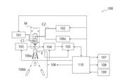
- FIG. 5 is a diagram showing a configuration example of the fine particle analyzer 100 according to the first embodiment.
- the microparticle sorting device 100 includes an image pickup element E that acquires an image of the fluid and the droplet at a position where the liquid discharged from the orifice that generates the fluid stream is dropletized, and the image. It has a processing unit 105 that determines the harmonic superposition amplitude ratio, the harmonic phase difference, and the superimposition wave voltage based on the state of the satellite droplets and the break-off point inside.
- the image pickup element (camera) E is the fluid before droplet formation at the break-off point where the laminar flow of the sample liquid and the sheath liquid discharged from the orifice that generates the fluid stream is dropletized. And the droplets are imaged.
- various image pickup elements such as a photoelectric conversion element can be used for image pickup of fluids and droplets.
- the image sensor E is provided with a position adjusting mechanism (not shown) for changing the position. This makes it possible to easily control the position of the image pickup device E according to the instruction of the control unit 110 described later.
- the fine particle sorting device 100 of the present embodiment may be provided with a light source (not shown) for illuminating the photographing region in addition to the image pickup device E.
- the processing unit 105 determines the harmonic superposition amplitude ratio, the harmonic phase difference, and the superimposition wave voltage based on the states of the satellite droplets and the break-off point in the image acquired by the image sensor E.
- the processing unit 105 can be configured by, for example, an information processing device including a general-purpose processor, a main storage device, an auxiliary storage device, and the like.
- the image data captured by the image pickup element E is input to the processing unit 105, and the programmed control algorithm is executed to determine the harmonic superimposition amplitude ratio, the harmonic phase difference, and the superimposition wave voltage. Is possible.
- the processing unit 105 can be stored as a program in a hardware resource including a recording medium (nonvolatile memory (USB memory, etc.), HDD, CD, etc.) and can be operated by a personal computer or a CPU. Further, the processing unit 105 may be connected to each unit of the fine particle sorting device 100 via a network.
- a recording medium nonvolatile memory (USB memory, etc.), HDD, CD, etc.
- This flow path may be provided in advance in the fine particle sorting device 100, but it is also possible to install a disposable microchip or the like provided with a flow path described later on the device for sorting. be.
- the form of the flow path is not particularly limited and can be freely designed as appropriate. In this embodiment, it is particularly preferable to use a flow path formed in a substrate such as two-dimensional or three-dimensional plastic or glass.
- the channel width, channel depth, channel cross-sectional shape, etc. of the channel are not particularly limited as long as they can form a laminar flow, and can be freely designed.
- a microchannel having a channel width of 1 mm or less can also be used in the minute preparative measuring device 100 according to the present embodiment.
- a microchannel having a channel width of 10 ⁇ m or more and 1 mm or less is preferably used.
- FIG. 6 is a diagram showing a configuration example of the microchip M
- FIG. 7 is a diagram showing a configuration example of the orifice M1 of the microchip M.
- a in FIG. 6 is a schematic top view
- B in FIG. 6 is a schematic cross-sectional view corresponding to the PP cross-section in A.
- a in FIG. 7 is a top view
- B in FIG. 7 is a sectional view
- C in FIG. 7 is a front view.
- the microchip M includes a sheath liquid flow path M41 that communicates with the main flow path M2 and allows the sheath liquid to flow through, a sheath liquid introduction unit M4 that introduces the sheath liquid, and the sheath liquid introduction unit M4.
- the sample liquid flow path M31 that communicates with the main flow path M2 and allows the sample liquid containing fine particles to flow through, the sample liquid introduction unit M3 that introduces the sample liquid, and the confluence part where the sample flow is introduced and merges with the sheath liquid. It is formed.
- the sheath liquid introduced from the sheath liquid introduction unit M4 is divided into two directions and then fed, and then the sample liquid is sandwiched from two directions at the confluence with the sample liquid introduced from the sample liquid introduction unit M3. And join the sample solution.
- a three-dimensional laminar flow in which the sample laminar flow is located in the center of the sheath laminar flow is formed at the confluence portion.
- the M51 shown in FIG. 6A is a suction for clearing the clogging or air bubbles by applying a negative pressure to the main flow path M2 to temporarily reverse the flow when the main flow path M2 is clogged or bubbles are generated. Shows the flow path.
- a suction opening M5 connected to a negative pressure source such as a vacuum pump is formed at one end of the suction flow path M51. Further, the other end of the suction flow path M51 is connected to the main flow path M2 at the communication port M52.
- the narrowing portions M61 (see A in FIG. 6) and M62 (see FIG. 7) are formed so that the area of the cross section perpendicular to the liquid feeding direction gradually or gradually decreases from the upstream to the downstream in the liquid feeding direction.
- the laminar flow width is narrowed down in (see A and B). After that, the three-dimensional laminar flow is discharged as a fluid stream from the orifice M1 provided at one end of the flow path.
- the fluid stream ejected from the orifice M1 is made into droplets by applying vibration to the sheath liquid flowing through the sheath liquid introduction portion M4 by the sheath liquid converging portion C21 described later. preferable.
- the orifice M1 is open in the direction of the end faces of the substrate layers Ma and Mb, and a notch M11 is provided between the opening position and the end face of the substrate layer.
- the notch M11 is formed by cutting out the substrate layers Ma and Mb between the opening position of the orifice M1 and the end face of the substrate so that the diameter L1 of the notch M11 is larger than the opening diameter L2 of the orifice M1. (See C in FIG. 7).
- the diameter L1 of the notch M11 is preferably formed to be at least twice as large as the opening diameter L2 of the orifice M1 so as not to hinder the movement of the droplets ejected from the orifice M1.
- micro means that at least a part of the flow path included in the microchip M has dimensions on the order of ⁇ m, particularly cross-sectional dimensions on the order of ⁇ m. That is, in the present technology, the “microchip” refers to a chip including a flow path on the order of ⁇ m, particularly a chip including a flow path having a cross-sectional dimension on the order of ⁇ m. For example, a chip including a particle sorting portion composed of a flow path having a cross-sectional dimension on the order of ⁇ m can be called a microchip according to the present technology.
- the microchip M can be manufactured by a method known in the art.
- the microchip M is formed by laminating the substrate layers Ma and Mb on which the main flow path M2 is formed.
- the formation of the main flow path M2 on the substrate layers Ma and Mb can be performed, for example, by injection molding of a thermoplastic resin using a mold.
- the flow path may be formed on all of two or more substrates, or may be formed only on a part of two or more substrates.
- the microchip M may be formed of three or more substrates by further bonding the substrates from the upward, downward, or both directions with respect to the plane of the substrate on which each flow path is formed.
- the material for forming the microchip M a material known in the art can be used.
- examples thereof include, but are not limited to, polycarbonate (PC), cycloolefin polymer, polypropylene, PDMS (polydimethylsiloxane), polymethylmethacrylate (PMMA), polyethylene, polystyrene, glass, silicon and the like.
- PC polycarbonate
- PDMS polydimethylsiloxane
- PMMA polymethylmethacrylate
- polyethylene polystyrene
- glass silicon and the like.
- polymer materials such as polycarbonate, cycloolefin polymer, and polypropylene are particularly preferable because they are excellent in processability and can be inexpensively manufactured using a molding apparatus.
- the microchip M is preferably transparent.
- at least a portion through which light (laser light and scattered light) passes may be transparent, and the entire microchip M may be transparent.
- the "sample” contained in the sample liquid is particularly fine particles, and the fine particles may be particles having dimensions capable of flowing in the flow path in the microchip M.
- fine particles may be appropriately selected by those skilled in the art.
- examples of the fine particles include biological fine particles such as cells, cell clumps, microorganisms, and liposomes, and synthetic fine particles such as gel particles, beads, latex particles, polymer particles, and industrial particles. Can be included.
- Biological microparticles can include chromosomes, ribosomes, mitochondria, organelles (organelles), etc. that make up various cells.
- the cells may include animal cells (eg, blood cell lineage cells, etc.), plant cells.
- the cell can be, in particular, a blood-based cell or a tissue-based cell.
- the blood line cell may be, for example, a floating line cell such as a T cell or a B cell.
- the tissue-based cells may be, for example, adherent cultured cells or adherent cells separated from the tissue.
- the cell mass may include, for example, spheroids, organoids and the like.
- Microorganisms may include bacteria such as Escherichia coli, viruses such as tobacco mosaic virus, and fungi such as yeast. Furthermore, the biological microparticles may also include biological macromolecules such as nucleic acids, proteins, and complexes thereof. These biological macromolecules may be, for example, those extracted from cells or may be contained in blood samples or other liquid samples. Synthetic fine particles can be, for example, fine particles made of an organic or inorganic polymer material, a metal, or the like.
- Organic polymer materials may include polystyrene, styrene / divinylbenzene, polymethylmethacrylate and the like.
- Inorganic polymer materials may include glass, silica, magnetic materials and the like.
- the metal may include colloidal gold, aluminum and the like.
- the synthetic microparticles may be, for example, gel particles, beads, etc., in particular gel particles or beads to which one or more combinations selected from oligonucleotides, peptides, proteins, and enzymes are bound. It's okay.
- the shape of the fine particles may be spherical or substantially spherical, or may be non-spherical.
- the size and mass of the fine particles can be appropriately selected by those skilled in the art depending on the size of the flow path of the microchip M.
- the size of the flow path of the microchip M can also be appropriately selected depending on the size and mass of the fine particles.
- the microparticles may be optionally attached with chemical or biological labels such as fluorescent dyes, fluorescent proteins and the like.
- the label may facilitate the detection of the microparticles.
- the fine particles are preferably biological particles, and may be cells in particular.
- the flow cell may be provided in advance in the fine particle sorting device 100, but it is also possible to install a commercially available flow cell or the like on the device and perform sorting.
- the form of the flow path formed in the flow cell is not particularly limited and can be freely designed.
- the flow path formed in the substrate such as two-dimensional or three-dimensional plastic or glass, but also the flow path as used in the conventional flow cytometer can be used in this technique.
- the fine particle sorting device 100 further includes a connecting member that can be attached to the microchip M and has a sheath liquid introduction connecting portion C2 that is connected to the sheath liquid introducing portion M4.
- FIG. 8 is a diagram showing a configuration example of the microchip M and the connecting member C.
- the connection member C shown in FIG. 8 has at least a sample introduction connecting portion C1 connected to the sample liquid introducing portion M3 and a sheath liquid introducing connecting portion C2 connected to the sheath liquid introducing portion M4.
- the connecting member C that can be attached to and detached from the microchip M, when a large number of different fine particles are continuously separated by using one device, a part of the constituent articles of the device can be removed. Become. Therefore, even if the fine particles contained in the previously separated fluid flow remain in the component, the component can be removed together with the component, and the risk of contamination can be reduced. Further, by disposing of the microchip M and the connecting member C for each sample, the labor of the cleaning operation performed when changing the sample can be saved, and the burden on the operator can be reduced.
- the sheath liquid introduction connecting portion C2 may have a liquid feeding tube capable of feeding liquid from the sheath liquid feeding portion 101. Further, the liquid feeding tube may have a tube-to-tube connecting portion that is directly connected to the sheathed liquid feeding portion 101. In this case, it is preferable that the tube-to-tube connecting portion is configured so that the liquid in the liquid feeding tube does not come into contact with the outside air. As a result, the cleanliness of the sheath liquid can be ensured.
- the sample liquid introduction connecting portion C1 may have a tube fixing portion for fixing a liquid feeding tube capable of feeding liquid from the sample liquid feeding unit 102.
- the liquid feeding tube can be formed integrally with the connecting member C, but can also be formed separately.
- the liquid feeding tube and the tube fixing portion capable of feeding liquid from the sample liquid feeding portion 102 are formed so as to be removable from the connecting member C, and are arranged at a place different from the sheath liquid feeding portion 101. It is possible to facilitate the connection with the sample liquid feeding unit 102.
- the vibration element C3 is attached to the connection member C. As a result, it is possible to propagate the vibration to the sheath liquid passing through the sheath liquid introduction portion M4 of the microchip M and induce the formation of droplets after being ejected from the orifice M1.
- the vibration element C3 is controlled by the vibration control unit.
- the vibration element C3 and the vibration control unit are referred to as a “vibration unit”.
- the sheath liquid introduction connecting portion C2 has a sheath liquid converging portion C21 whose width gradually or partially narrows from the side to which the vibration element C3 is attached toward the sheath liquid introduction portion M4 side. Is preferable.
- the thickness of the flow path in the sheath liquid introduction connecting portion C2 is gradually narrowed from the thickness of the vibration element C3 to the thickness of the sheath liquid introduction portion M4, and the scale and flow are as large as the vibration element C3. It is possible to connect the scale of the size of a path, concentrate the vibration energy of the vibration element C3 in the vicinity of the sheath liquid introduction portion M4, and efficiently send the vibration energy to the flow path in the microchip M with a small drive voltage. ..
- the sheath liquid is supplied from the sheath liquid feeding unit 101 to the sheath liquid converging part C21, and the sheath liquid is vibrated by the vibrating element C3 arranged upstream of the sheath liquid converging part C21.
- the vibrating element C3 is composed of, for example, a piezoelectric element portion and a piston portion, each of which is firmly bonded by an adhesive or the like.
- the structure of the piezoelectric element portion does not matter as long as the vibration finally taken out is in the desired direction and can be vibrated with the required amplitude at the target vibration frequency.
- a laminated type, a square plate type, a disk type, a tube type, or the like can be considered.
- the vibrating element C3 a magnetic force such as a permanent magnet and a solenoid may be used.
- the structure may be such that the bending type piezoelectric element is attached to the top surface of the sheath liquid converging portion C21.
- the sheath liquid is sent into the chip from the sheath liquid introduction portion M4 of the microchip M, and the vibration of the vibrating element C3 propagates through the sheath liquid to induce the formation of droplets after being ejected from the orifice M1.
- the vibration element C3 for example, a piezoelectric element such as a piezo element can be used, but as described above, a vibration element that converts electrical energy into vibration via a magnetic force such as a permanent magnet and a solenoid can be used.
- the frequency is not limited to the ultrasonic region of 20 kHz or more, and can be appropriately set according to the size of the droplet to be formed.
- the material for forming the sheath liquid converging portion C21 a material known in the art can be used, but in the present technology, it is preferable to form the sheath liquid converging portion C21 with a resin, a metal, or a transparent member.
- the resin for example, polyetheretherketone (PEEK) or the like can be used.
- the transparent member for example, polymethyl methacrylate (PMMA), polycarbonate (PC) or the like can be used.
- PMMA polymethyl methacrylate
- PC polycarbonate
- the sheath liquid converging portion C21 By forming the sheath liquid converging portion C21 with the transparent member, the inside of the sheath liquid converging portion 21 can be observed.
- the metal for example, stainless steel, aluminum alloy, titanium alloy and the like can be used. By forming the sheath liquid converging portion C21 from metal, it is possible to omit the electrode for droplet charging.
- the electrode C4 is inserted into the sheath liquid converging portion C21 as shown in FIG. Then, the droplet can be charged through the sheath liquid.
- the purpose of this is to make the distance between the droplet splitting point and the electrode C4 as close as possible, and to perform charging at a timing closer to the ideal.
- the microchip M and the connecting member C can be appropriately removed as needed, and may be disposable. Further, the vibrating element C3 attached to the connecting member C may also be distributed while being attached to the connecting member C in advance. In this case, the vibrating element C3 may be disposable.
- FIGS. 9A and 9B are diagrams showing a configuration example when the present technology is applied when the flow path is formed in a flow cell instead of the microchip M.
- the sheath liquid and the sample liquid are first poured into a conical container.
- the cone is installed with its apex vertically downward, and a sheath fluid tube is connected to the upper side surface.
- the upper surface of the container is open, and the vibration unit is attached in a state of being sealed with an O-ring. Since the cell fluid is injected vertically from above the container, the piezo and the piston have an annular shape, and the pipe passes through the central hole thereof.
- the sheath liquid converging portion C21 has a conical shape, narrows at the lowermost portion, and is connected to a flow path (cuvette tube) at the tip. Fine particle inspection by laser irradiation is performed in this flow path.
- An outlet nozzle is installed at the end point of the flow path, and the connection portion has a slope shape so as to be continuously narrowed.
- the sample liquid is directly subjected to a minute vibration of ⁇ several tens of nm level in the front-rear direction with respect to the flow from the piezo actuator unit mounted directly above the conical container.
- the vibrating element operates in a sinusoidal shape at a desired frequency f.
- a sine wave such as 2f, 3f, 4f, etc., which is an integral multiple of this frequency f, to give asymmetry to the pushing and pulling operation of the vibrating element, satellite SLOW or FAST can be controlled. This is due to the effect of giving the initial constriction an asymmetry in the flow anterior-posterior direction and growing it into a shape suitable for each satellite formation immediately before the droplet splitting.
- the constriction shape immediately before the fragmentation is characteristic, and as shown in FIGS. 1 and 3, the droplet portion is elongated with respect to the SLOW satellite, and the position where it becomes the widest moves slightly forward in the flow direction. It is connected to the liquid thread like a tail. In the present embodiment, it is an object to artificially form such a shape.
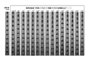
- the satellite transitions from SLOW to FAST according to the change in the phase difference, and the one close to INFINITY, which requires a long cycle to recover the satellite after droplet splitting, is recovered early in 2 to 3 cycles. It shows how the state of things changes from moment to moment. From the results shown in FIG. 10, it can be seen that such a state change of the satellite is associated with the shape change in the droplet formation process described above.
- a combined wave of a sine wave having a fundamental frequency f and a sine wave having an integral multiple frequency thereof (2f, 3f, 4f ...) may be used as a drive signal of the vibrating element.
- the drive signal of the vibrating element and the actual operation do not always match. This is because the amplitude ratio and phase difference between the fundamental frequency and the harmonics may not be kept constant depending on the frequency characteristics of the vibrating element itself and the electric circuit that supplies the signal to the vibrating element.
- the amplitude rapidly increases in the vicinity of the resonance frequency fr of the vibration unit, and the phase of the response waveform changes rapidly with respect to the input waveform. If the resonance frequency shifts due to factors such as changes in the element temperature during operation, the operation of the vibration unit may change significantly. Therefore, in order to realize stable droplet formation, it is better to avoid using the resonance frequency near fr. Specifically, it is preferable to select one type of harmonic frequency fh that is separated from the resonance frequency fr of the vibrating element C3 by ⁇ 10 kHz or more.
- a harmonic sine wave of a known frequency is used instead of a square wave or a sawtooth wave. It is possible to generate a FAST satellite even when the piezo is driven by a square wave or a sawtooth wave, but it has multiple high-order components such as 2 times, 3 times, 4 times, and 5 times, respectively, and either frequency. May approach the resonance frequency of the vibration unit, so it often lacks stability over time.
- the vibration element is selected in consideration of the fundamental frequency that is supposed to be used and the operation at twice and three times the frequency, and the piston is used so that the resonance frequency fr does not approach the harmonics of the vibration unit as a whole. It is necessary to design the weight, etc., and measure and understand the frequency characteristics after completion. If possible, it is desirable that the amplitude and phase of the fundamental wave and the harmonics match, and that there is no difference in the operation of the piezo drive signal and the actual vibration unit.
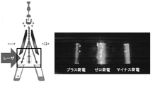
- the operation of the vibration control unit in the vibration unit distorts the sine wave movement and displaces the vibration element C3. It is preferable to operate the waveform so that the pushing operation and the pulling operation are asymmetric in the time axis direction.
- FIG. 11 shows three types of waveforms.
- waveform A the rising speed to the plus side (push side) is faster than the falling speed to the minus side (pulling side).
- the waveform B is a waveform in which a recess is generated in the middle, the rising and falling speeds are equal, and the waveform B is symmetrical in the time axis direction.
- the waveform C is a waveform obtained by inverting the waveform A in the time axis direction, and the falling speed to the minus side (pulling side) is faster than the rising speed to the plus side (pushing side).
- the signal generator supplies a synchronized signal to the following three systems of outputs that are synchronized with each other and a charged signal generator for timing adjustment with the charged signal.
- (C) Output C Illumination for droplet observation (Signal for strobe light emission Wl) The LED lighting is turned ON / OFF at the fundamental frequency f in synchronization with the piezo drive signal, and the droplet is observed in a stationary state. Further, when the phase is adjusted with respect to Wf, observation can be performed at an arbitrary time within one cycle of the droplet.
- the piezo drive signals of (a) and (b) are superimposed on a dedicated piezo driver having a sufficient current supply capacity, and after amplification, they are output to the piezo element as superimposed waves Ws.
- the piezo driver is provided with an output voltage variable function of the superimposed waveform Ws, which enables fine adjustment of BOP described later.
- the flow rate of the sheath liquid injected from the pressure tank into the device is adjusted by the pressure of the air compressor for pressurization.
- the sine wave Wf of frequency f is output to the piezo actuator via the piezo driver. Adjust the voltage of the sine wave so that the BOP length as a guide can be obtained.
- the harmonic phase difference ⁇ is determined by fixing it to the harmonic superimposition amplitude ratio R value obtained in Step 1. Again, while observing the droplets, find ⁇ to obtain the desired FAST satellite. At that time, avoid the point of sudden transition from the FAST satellite to the SLOW satellite side with respect to the phase change, and set it to ⁇ , which minimizes the satellite fluctuation, in order to maintain the stability over time after the start of measurement. desirable.
- FIG. 14 is a graph showing the change in BOP length due to the harmonic phase difference ⁇ .
- the harmonic phase difference ⁇ is in the range of 0 to 100 ° and 200 to 250 °, the BOP length changes greatly due to the phase difference fluctuation, so it was avoided from the viewpoint of long-term stability. Better.
- the BOP length fluctuation range is 4 mm or more due to the phase difference change, and the droplet jitter increases especially in the range of ⁇ of 120 ° to 150 °.
- the area can be seen. This is because R is too large, and it is necessary to reduce it to an appropriate value by the above-mentioned method.
- the BOP fluctuation occurs for the droplets formed only by the fundamental wave Wf of the above [2]. If necessary, the voltage of the piezo driver is adjusted, and the superimposed wave Ws output voltage Vs is determined so as to obtain a desired BOP value while maintaining the waveform of the superimposed wave Ws determined in the above [4].
- the droplet BOP may fluctuate from the state before measurement due to factors such as the fact that fine particles actually start to flow or the temperature and humidity around the device change. Furthermore, there may be a case where the satellite shifts to the SLOW side and normal deflection operation cannot be maintained. At that time, it is necessary to make the following readjustments.
- BOP fluctuations of several tens of microns can easily occur, but due to deviations from the droplet charge timing in deflection, changes in the deflection angle and, in some cases, erroneous deflection of the anterior-posterior droplet of the target droplet. cause. Therefore, it is necessary to make adjustments as needed so that the BOP is kept within ⁇ 10 ⁇ m.
- the superimposed wave Ws output voltage Vs is finely adjusted by the same procedure as in [5] above so that the BOP position maintains the initial position. It is desirable that this work can be processed automatically at all times without interrupting the measurement.
- the harmonic phase difference ⁇ between the fundamental wave Wf and the harmonic Wh is adjusted again. Further, the harmonic superimposition amplitude ratio R may also need to be readjusted. If the FAST satellite is not generated even after adjusting the harmonic phase difference ⁇ , it is advisable to increase the amplitude of the harmonic Wh to increase R. Further, when the dispersion of the deflection angle is widened from the beginning or becomes band-shaped, the droplet jitter may be slightly increased below the visible level. In such a situation, it may be improved by lowering the amplitude of the harmonic Wh. Since the BOP position is changed when this adjustment is performed, the BOP adjustment work of the above [6] is also required.
- FIG. 15 is a diagram showing a configuration example of the fine particle sorting device according to the second embodiment.
- the fine particle sorting device 100 according to the present embodiment is discharged from a light irradiation unit 103 that irradiates the fine particles with light, a light detection unit 104 that detects the light from the fine particles, and an orifice that generates a fluid stream.
- Harmonic superposition amplitude ratio based on the state of the satellite droplets and break-off points in the image and the image pickup element E that acquires the image of the fluid and the droplets at the position where the liquid is dropletized.
- a droplet forming unit a preparative unit 106, a storage unit 107, a display unit 108, an input unit 109, a control unit 110, and the like may be provided. Since the image sensor E and the processing unit 105 are the same as those described above, the description thereof is omitted here.
- the light irradiation unit 103 irradiates the fine particles to be sorted with light (for example, excitation light).
- the light irradiation unit 103 may include a light source that emits light and an objective lens that collects excitation light for fine particles flowing in the detection region.
- the light source may be appropriately selected by those skilled in the art depending on the purpose of sorting, and may be, for example, a laser diode, a SHG laser, a solid-state laser, a gas laser, or a high-intensity LED, or two or more of them. It may be a combination of.
- the light irradiation unit 103 may include other optical elements, if necessary, in addition to the light source and the objective lens.
- the photodetection unit 104 detects light (scattered light and / or fluorescence) generated from the fine particles by irradiation by the light irradiation unit 103.
- the photodetector 104 may include a condenser lens that collects fluorescence and / or scattered light generated from fine particles, and a photodetector.
- a PMT, a photodiode, a CCD, a CMOS, or the like can be used, but the present technology is not limited to these.
- the light detection unit 104 may include other optical elements, if necessary, in addition to the condenser lens and the photodetector.
- the photodetector 104 may further include, for example, a spectroscopic unit.
- a spectroscopic unit examples include a grating, a prism, an optical filter, and the like.
- the spectroscopic unit can, for example, detect light having a wavelength to be detected separately from light having another wavelength.
- the fluorescence detected by the light detection unit 104 may be fluorescence generated from the fine particles themselves or a substance labeled with the fine particles, for example, a fluorescent substance, but the present technology is not limited to these.
- the scattered light detected by the light detection unit 104 may be forward scattered light, side scattered light, Rayleigh scattering, or Mie scattering, or may be a combination thereof.
- the droplet forming portion vibrates the fluid using the vibrating element C3 to form droplets on the fluid.
- the vibrating element C3 is preferably provided so as to be in contact with the flow path, and more preferably provided in the vicinity of the fluid discharge port of the flow path.
- the vibration element C3 is controlled by the vibration control unit. Since the vibrating element C3 is the same as that described above, the description thereof is omitted here.
- Sorting unit 106 (including charged unit 106c)
- the preparative unit 106 has at least a polarizing plate 106a that changes the charged droplets in a desired direction, and a collection container 106b (for example, a cylindrical container having a diameter of 5 mm) that collects the droplets.
- the charging unit 106c which is separately defined on FIG. 15, is a part of the preparative unit 106, and charges the electric charge based on the preparative control signal generated by the processing unit 105.
- the vibrating element C3 attached to the connecting member C forms droplets by propagating vibration to the sheath liquid as described above.
- the charged portion 106c is connected to the electrode C4 inserted into the sheath liquid converging portion C21 described above, and the droplets ejected from the orifice M1 of the microchip M are positively or negatively added based on the preparative control signal generated by the processing unit 105. Charged to.
- a charge is applied to the droplets ejected from the orifice 21 formed on the microchip M.
- the charged unit 106c is arranged upstream of the image pickup device E, for example, as shown in FIG. Then, the path of the charged droplet is changed in a desired direction by the deflection plate (opposite electrode) 106a to which the voltage is applied, and the droplet is separated.
- the storage unit 107 stores all matters related to measurement such as the value detected by the optical detection unit 103, the feature amount calculated by the processing unit 105, the preparative control signal, and the preparative conditions input by the input unit. do.
- the storage unit 107 is not essential, and an external storage device may be connected.
- the storage unit 107 for example, a hard disk or the like can be used.
- the recording unit 107 may be connected to each unit of the fine particle sorting device 100 via a network.
- the display unit 108 can display all items related to measurement such as the value detected by the light detection unit 103 and the feature amount calculated by the processing unit 105.
- the display unit 108 preferably displays the feature amount for each fine particle calculated by the processing unit 105 as a scattergram.
- the display unit 108 is not essential, and an external display device may be connected.
- the display unit 110 for example, a display, a printer, or the like can be used.
- the display unit 108 may be connected to each unit of the fine particle sorting device 100 via a network.
- the input unit 109 is a part for a user such as an operator to operate.
- the user can access the control unit 110 described later through the input unit 109 and control each unit of the fine particle sorting device 100.
- the input unit 109 preferably sets a region of interest for the scattergram displayed on the display unit 108, and determines the preparative conditions.
- the input unit 109 is not essential, and an external operating device may be connected.
- an external operating device for example, a mouse, a keyboard, or the like can be used. Further, the input unit 109 may be connected to each unit of the fine particle sorting device 100 via a network.
- the control unit 110 is configured to be able to control each of the light irradiation unit 103, the light detection unit 104, the analysis unit 105, the preparative unit 106, the charge unit 106c, the recording unit 107, the display unit 108, and the input unit 109.
- the control unit 110 may be separately arranged for each unit of the fine particle sorting device 100, or may be provided outside the fine particle sorting device 100. For example, it may be carried out by a personal computer or a CPU, and further, it may be stored as a program in a hardware resource including a recording medium (nonvolatile memory (USB memory, etc.), HDD, CD, etc.), and the personal computer or CPU may be used. It is also possible to make it work by. Further, the control unit 110 may be connected to each unit of the fine particle sorting device 100 via a network.
- the fine particle sorting system includes an image pickup device that acquires an image of the fluid and the droplet at a position where the liquid discharged from the orifice that generates the fluid stream is dropletized, and the image in the image. It has a processing device that determines the harmonic superposition amplitude ratio, harmonic phase difference, and superimposition wave voltage based on the state of the satellite droplet and the break-off point.
- the description thereof is omitted here. Further, since the method performed in the processing apparatus is the same as the method performed in the processing unit 105 described above, the description thereof is omitted here.
- the method for separating fine particles includes an imaging step of acquiring an image of the fluid and the droplet at a position where the liquid discharged from the orifice generating a fluid stream is dropletized, and an imaging step in the image. It has a processing step of determining the harmonic superposition amplitude ratio, the harmonic phase difference, and the superimposition wave voltage based on the state of the satellite droplets and the break-off point.
- the description thereof is omitted here. Further, since the method performed in the processing step is the same as the method performed in the processing unit 105 described above, the description thereof is omitted here.
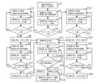
- the flow shown in FIG. 16 is when there is a change in the fundamental frequency f or the flow velocity V, or when there is a possibility of a large state change such as after nozzle replacement, and the adjustment is started from zero because the guideline of the superimposed waveform cannot be established. The most certain. It is assumed that the harmonic frequency fh (2nd harmonic, 3rd harmonic, etc.) is selected in advance from the characteristics of the piezo actuator.
- the minimum value Rmin of the harmonic superimposition amplitude ratio R is determined (S8, S22).
- the harmonic phase difference ⁇ is made to go around from 0 ° to 360 °, and the state of the droplets and satellites is observed (S10, S23).
- S24 the fluctuation of BOP is not more than a predetermined value or no increase in jitter is observed (S11, S25), the process returns to S9 or S23.
- the maximum value Rmax of the harmonic superimposition amplitude ratio R is determined (S12, S26). After determining the minimum value Rmin and the maximum value Rmax of R from the above steps, R is determined as an intermediate value (S13). Next, the harmonic phase difference ⁇ is adjusted (S14), the FAST satellite appears, and the value that minimizes the BOP volatility with respect to the phase change is searched for, and if the value is not found (S15), Change the setting of ⁇ (S16) and return to S14.
- the harmonic phase difference ⁇ is determined (S17).
- the output voltage Vs of the superimposed wave Ws is adjusted using the BOP length as a criterion (S18).
- the flow shown in FIG. 17 realizes a reduction in the condition setting time when it is expected that there is no change in the measurement conditions or a large change in the device state such as restarting after the measurement is interrupted.
- the flow may be returned to the flow shown in FIG. ..
- the harmonic frequency fh (2nd harmonic, 3rd harmonic, etc.) is selected in advance from the characteristics of the piezo actuator.
- the range of the BOP fluctuation range accompanying the phase change is predetermined as a guideline for reproducibility (for example, 2.0 ⁇ 0.5 mm), and the range is within this range. It is okay if it is (S115).
- the harmonic phase difference ⁇ is adjusted (S116), the FAST satellite appears, and the value that minimizes the BOP volatility with respect to the phase change is searched for, and the value is found. If not (S117), change the setting of ⁇ (S118) and return to S116.
- the FAST satellite does not appear in S104 (S104), increase the set value of the harmonic superimposition amplitude ratio R (S105), and then observe the state of the satellite (S106).
- the process returns to S105.
- a FAST satellite appears (S106) it is confirmed whether or not the BOP fluctuation range is larger than a predetermined value (S107).
- the BOP fluctuation width is not larger than the predetermined value (S107)
- the harmonic phase difference ⁇ is made to go around from 0 ° to 360 °, and the droplet is formed. , Observe the state of the satellite (S113).
- the flow shown in FIG. 18 tends to be the point where the BOP length is the shortest with respect to ⁇ because the BOP length is stable with respect to the change of the FAST satellite and the harmonic phase difference ⁇ . Is strong. Therefore, it is conceivable to first rotate ⁇ 360 ° at an appropriate amplitude ratio R and determine ⁇ at the angle at which BOP is the shortest. It is assumed that the harmonic frequency fh (2nd harmonic, 3rd harmonic, etc.) is selected in advance from the characteristics of the piezo actuator.
- the value of the harmonic superimposition amplitude ratio R is set by adopting the conventional one (S1002). If the initial harmonic superimposition amplitude ratio R is a known value that has been conventionally used under the same conditions, there is a high possibility that it can be used as it is.
- the harmonic phase difference ⁇ is made to go around from 0 ° to 360 °, and the state of the droplets and satellites is observed (S1006).
- the BOP value is not the minimum (S1004), change the setting of ⁇ (S1005) and return to S1003.
- the harmonic phase difference ⁇ is determined (S1006).
- the harmonic superimposition amplitude ratio R is determined (S1019).
- the FAST satellite does not appear in S1007, increase the set value of the harmonic superimposition amplitude ratio R (S1008) and then observe the state of the satellite (S1009).
- the FAST satellite does not appear (S1009), it returns to S1008.
- the harmonic phase difference ⁇ is set to 0 °. The state of droplets and satellites is observed by making a full circle from 1 to 360 ° (S1016).
- the harmonic superimposed amplitude ratio R is determined (S1014). After the value of R is decided, it moves to S1020. On the other hand, if the FAST satellite does not appear or the BOP fluctuation range is not within the predetermined value (S1017), the process returns to S1015.
- the BOP fluctuation range is not larger than the predetermined value in S1010 (S1010), increase the set value of the harmonic superimposition amplitude ratio R (S1011), and then rotate the harmonic phase difference ⁇ from 0 ° to 360 °. Then, observe the state of droplets and satellites (S1012).
- the harmonic superimposed amplitude ratio R is determined (S1014). After the value of R is decided, it moves to S1020.
- the FAST satellite does not appear or the BOP fluctuation range is not within the predetermined value (S1013), the process returns to S1011.
- the user can determine the presence / absence of FAST satellite generation, the fluctuation range of the BOP length, and the occurrence of jitter in a very short time from the droplet observation image, and the above adjustments can be made. Shorten the procedure.
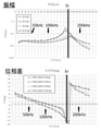
- FIG. 19 is a diagram showing an example of the frequency characteristics of the piezo actuator.
- the self-resonant frequency fr is at 160 kHz
- the vibration amplitude starts to rise from around 110 kHz
- has a peak at 150 to 170 kHz and reaches about 10 times that of 100 kHz or less.
- the phase except for the resonance frequency, the phase continues to be gradually delayed at a constant value of about 10 ° per 10 kHz, but shows a rapid change of ⁇ 180 ° at 10 kHz before and after 170 kHz. Therefore, in the piezo actuator shown in FIG. 19, use at 150 kHz to 170 kHz causes instability and should be avoided.
- FIG. 20 shows the results of comparing the piezo actuator drive waveform (after driver amplification) and the actual piston displacement waveform for both.
- the piston displacement waveform was obtained by laser Doppler measurement with the actuator removed from the device and placed in the water.
- the flow velocity V of the jet is determined according to the droplet frequency.
- the jet is composed of cell fluid and sheath fluid, but since the sheath fluid occupies most of the volume, it is controlled by the flow velocity of the sheath fluid. Therefore, first, a pressure P is applied to the pressure tank for the sheath liquid by an air compressor, the valve is opened, and the flowing liquid is started. Assuming that the pressure loss of the liquid feeding system is PL, the relationship with the flow velocity V is “P ⁇ (1/2) ⁇ ( ⁇ ⁇ V 2 ) + PL”. ( ⁇ ; sheath liquid density)
- the pressure required to form a jet with a flow velocity V 31.5 m / s changes from the above equation (1/2) ⁇ ( ⁇ ⁇ V 2 ) to 500 kPa, and when the pressure loss PL of the system is added to this, the required pressure P
- the standard is about 600 to 800 kPa.
- the pressure P is controlled by using an electropneumatic regulator having an accuracy of ⁇ 0.1% or less.
- the cell fluid is injected into the center of the sheath fluid, forms a central laminar flow called a core stream, and is discharged from the nozzle. Similar to the sheath liquid, the cell liquid tank is pressurized with an air compressor to send the liquid, but at that time, the core stream diameter is increased by giving a change ⁇ P of about 10% to the pressure P of the sheath liquid. Control.
- As the sheath liquid an IsoFlow sheath liquid manufactured by Beckman Coulter Co., Ltd., which is exclusively used for the flow cytometer, was used.
- the piezo driver signal output of the fundamental wave Wf was fixed at 1.2V, and the signal output of Wh was changed to adjust the amplitude ratio R of both.
- the results of observing the state of satellites while rotating the phase of Wh by 360 ° for the three types of amplitude ratios R 1/2, 1/6, and 1/12 are shown in FIGS. 21 to 23, respectively.
- the movement of the piston is considered to be tracing a waveform with folds in the middle of the period (see waveform B type in FIG. 6). Since the BOP expands and contracts violently and a jitter region is generated in this way, there is a concern about long-term stability under this condition.
- the charge signal is synchronized with the piezo drive signal, and the phase of the charge signal is adjusted to match the timing with the droplet formation cycle so that the deflection angle is maximized.
- a test pattern that deflects to the plus side and the minus side once every 10 cycles was used.
- the pulse width was 10 ⁇ sec, which corresponds to one cycle of 100 kHz, and the amplitude was ⁇ 100 V.
- the voltage between the deflection electrodes is ⁇ 2 kV.
- the state of deflection is shown in FIG.
- the positively and negatively charged deflection streams were narrowed down to the same fineness as the FAST satellite droplets generated only by the conventional fundamental sine wave, and were normal. Further, in an environment where the indoor temperature change was within ⁇ 0.5 ° C., the droplet shape and the deflection angle were maintained for 30 minutes without any adjustment during the process. After that, the BOP gradually extended by about 20 to 30 ⁇ m, and a slight decrease in the deflection angle was observed. At this time, when the output voltage of the superimposed waveform Ws was reduced by 1%, the original deflection angle was restored again.
- the method of the present invention applying the harmonic superimposed waveform to the piezo actuator drive shows the same deflection performance and temporal stability as the conventional basic sine wave drive, and there is no problem in practicality. It was confirmed.
- An image pickup element that acquires an image of the fluid and the droplet at a position where the liquid discharged from the orifice that generates the fluid stream is dropletized.
- a processing unit that determines the harmonic superposition amplitude ratio, harmonic phase difference, and superimposition wave voltage based on the state of satellite droplets and break-off points in the image.
- a fine particle sorting device [2] The fine particle sorting device according to [1], wherein the harmonic superimposition amplitude ratio is determined based on the maximum value and the minimum value of the amplitude ratio.
- the microchip further includes a main flow path through which a liquid containing fine particles flows, a sheath liquid flow path that communicates with the main flow path and supplies the sheath liquid, and a sheath liquid supply port that introduces the sheath liquid.
- the fine particle sorting device according to [9] further comprising a connecting member that can be attached to the microchip and has a sheath liquid introduction connecting portion that is connected to the sheath liquid supply port.
- the fine particle sorting device according to [10] wherein the vibration element is attached to the connecting member.
- a fine particle measuring apparatus wherein the sheath liquid introduction connecting portion has a sheath liquid converging portion whose width gradually or partially narrows from the vibrating element side toward the sheath liquid supply port side.
- a light irradiation unit that irradiates fine particles with light
- a photodetector that detects light from the fine particles
- An image pickup element that acquires an image of the fluid and the droplet at a position where the liquid discharged from the orifice that generates the fluid stream is dropletized.
- a processing unit that determines the harmonic superposition amplitude ratio, harmonic phase difference, and superimposition wave voltage based on the state of satellite droplets and break-off points in the image.
- a fine particle sorting device that determines the harmonic superposition amplitude ratio, harmonic phase difference, and superimposition wave voltage based on the state of satellite droplets and break-off points in the image.
- An image pickup device that acquires an image of the fluid and the droplet at a position where the liquid discharged from the orifice that generates the fluid stream is dropletized.
- a processing device that determines the harmonic superposition amplitude ratio, harmonic phase difference, and superimposition wave voltage based on the state of satellite droplets and break-off points in the image.
- Fine particle sorting device 100 Fine particle sorting device 101: Sheath liquid feeding unit 102: Sample liquid feeding unit 103: Light irradiation unit 104: Light detection unit 105: Processing unit 106: Sorting unit 106a: Deflection Plate 106b: Collection container 106c: Charged unit 107: Storage unit 108: Display unit 109: Input unit 110: Control unit M: Microchip Ma, Mb: Substrate layer M1: Orifice M11: Notch M2: Main flow path M3: Sample liquid Introducing part M31: Sample liquid flow path M4: Sheath liquid introduction part M41: Sheath liquid flow path M5: Suction opening M51: Suction flow path M52: Communication port M61, 62: Narrowing part M7: Straight part L1: Notch part M11 Diameter L2: Orifice M1 opening diameter C: Connecting member C1: Sample liquid introduction connecting part C21: Sheath liquid converging part C3: Vibration element C4: Electrode E: Imaging element
Landscapes
- Chemical & Material Sciences (AREA)
- Biochemistry (AREA)
- Physics & Mathematics (AREA)
- Health & Medical Sciences (AREA)
- Life Sciences & Earth Sciences (AREA)
- Analytical Chemistry (AREA)
- General Health & Medical Sciences (AREA)
- General Physics & Mathematics (AREA)
- Immunology (AREA)
- Pathology (AREA)
- Dispersion Chemistry (AREA)
- Engineering & Computer Science (AREA)
- Signal Processing (AREA)
- Automatic Analysis And Handling Materials Therefor (AREA)
Priority Applications (2)
| Application Number | Priority Date | Filing Date | Title |
|---|---|---|---|
| JP2022540058A JPWO2022024575A1 (https=) | 2020-07-28 | 2021-06-16 | |
| US18/005,650 US20230273108A1 (en) | 2020-07-28 | 2021-06-16 | Microparticle analysis device, microparticle sorting system, and microparticle analysis method |
Applications Claiming Priority (2)
| Application Number | Priority Date | Filing Date | Title |
|---|---|---|---|
| JP2020127147 | 2020-07-28 | ||
| JP2020-127147 | 2020-07-28 |
Publications (1)
| Publication Number | Publication Date |
|---|---|
| WO2022024575A1 true WO2022024575A1 (ja) | 2022-02-03 |
Family
ID=80035344
Family Applications (1)
| Application Number | Title | Priority Date | Filing Date |
|---|---|---|---|
| PCT/JP2021/022773 Ceased WO2022024575A1 (ja) | 2020-07-28 | 2021-06-16 | 微小粒子分析装置、微小粒子分取システム及び微小粒子分析方法 |
Country Status (3)
| Country | Link |
|---|---|
| US (1) | US20230273108A1 (https=) |
| JP (1) | JPWO2022024575A1 (https=) |
| WO (1) | WO2022024575A1 (https=) |
Cited By (1)
| Publication number | Priority date | Publication date | Assignee | Title |
|---|---|---|---|---|
| WO2023218986A1 (ja) * | 2022-05-13 | 2023-11-16 | ソニーグループ株式会社 | 液滴分取システム、液滴分取方法、及び液滴分取プログラム |
Citations (12)
| Publication number | Priority date | Publication date | Assignee | Title |
|---|---|---|---|---|
| JPS5543713B2 (https=) * | 1975-09-05 | 1980-11-07 | ||
| JPS61134262A (ja) * | 1984-12-05 | 1986-06-21 | Ricoh Co Ltd | 荷電偏向型インクジエツトヘツド |
| JPS6477548A (en) * | 1988-08-29 | 1989-03-23 | Fuji Xerox Co Ltd | Ultrasonic wave generating apparatus of ink jet printing head |
| JPH10507524A (ja) * | 1994-10-14 | 1998-07-21 | ユニバーシティ オブ ワシントン | 高速フローサイトメータ液滴形成システム |
| JP2006504970A (ja) * | 2002-11-01 | 2006-02-09 | ベックマン コールター,インコーポレーテッド | 液滴ソーティングの監視及び制御 |
| WO2015111293A1 (ja) * | 2014-01-24 | 2015-07-30 | ソニー株式会社 | 粒子分取装置及び粒子分取方法 |
| WO2017212717A1 (ja) * | 2016-06-10 | 2017-12-14 | ソニー株式会社 | 流体制御装置、微小粒子測定装置及び流体制御方法 |
| CN108295915A (zh) * | 2018-01-18 | 2018-07-20 | 北京航空航天大学 | 一种控制射流断裂与液滴生成的方法及装置 |
| WO2019103693A1 (en) * | 2017-11-24 | 2019-05-31 | Nanyang Technological University | Apparatus and method for three dimensional printing of an ink |
| JP2020076786A (ja) * | 2014-09-05 | 2020-05-21 | ソニー株式会社 | 液滴分取装置、液滴分取方法及びプログラム |
| WO2020149042A1 (ja) * | 2019-01-15 | 2020-07-23 | ソニー株式会社 | 微小粒子分取装置、微小粒子分取システム、液滴分取装置、及び液滴制御装置、並びに、液滴制御用プログラム |
| JP2021025866A (ja) * | 2019-08-05 | 2021-02-22 | アライドフロー株式会社 | 粒子分別装置及び粒子分別方法 |
Family Cites Families (2)
| Publication number | Priority date | Publication date | Assignee | Title |
|---|---|---|---|---|
| JP5910412B2 (ja) * | 2012-08-16 | 2016-04-27 | ソニー株式会社 | 微小粒子分取方法及び微小粒子分取用マイクロチップ |
| JP6102783B2 (ja) * | 2014-02-14 | 2017-03-29 | ソニー株式会社 | 粒子分取装置、粒子分取方法及びプログラム |
-
2021
- 2021-06-16 JP JP2022540058A patent/JPWO2022024575A1/ja active Pending
- 2021-06-16 US US18/005,650 patent/US20230273108A1/en active Pending
- 2021-06-16 WO PCT/JP2021/022773 patent/WO2022024575A1/ja not_active Ceased
Patent Citations (12)
| Publication number | Priority date | Publication date | Assignee | Title |
|---|---|---|---|---|
| JPS5543713B2 (https=) * | 1975-09-05 | 1980-11-07 | ||
| JPS61134262A (ja) * | 1984-12-05 | 1986-06-21 | Ricoh Co Ltd | 荷電偏向型インクジエツトヘツド |
| JPS6477548A (en) * | 1988-08-29 | 1989-03-23 | Fuji Xerox Co Ltd | Ultrasonic wave generating apparatus of ink jet printing head |
| JPH10507524A (ja) * | 1994-10-14 | 1998-07-21 | ユニバーシティ オブ ワシントン | 高速フローサイトメータ液滴形成システム |
| JP2006504970A (ja) * | 2002-11-01 | 2006-02-09 | ベックマン コールター,インコーポレーテッド | 液滴ソーティングの監視及び制御 |
| WO2015111293A1 (ja) * | 2014-01-24 | 2015-07-30 | ソニー株式会社 | 粒子分取装置及び粒子分取方法 |
| JP2020076786A (ja) * | 2014-09-05 | 2020-05-21 | ソニー株式会社 | 液滴分取装置、液滴分取方法及びプログラム |
| WO2017212717A1 (ja) * | 2016-06-10 | 2017-12-14 | ソニー株式会社 | 流体制御装置、微小粒子測定装置及び流体制御方法 |
| WO2019103693A1 (en) * | 2017-11-24 | 2019-05-31 | Nanyang Technological University | Apparatus and method for three dimensional printing of an ink |
| CN108295915A (zh) * | 2018-01-18 | 2018-07-20 | 北京航空航天大学 | 一种控制射流断裂与液滴生成的方法及装置 |
| WO2020149042A1 (ja) * | 2019-01-15 | 2020-07-23 | ソニー株式会社 | 微小粒子分取装置、微小粒子分取システム、液滴分取装置、及び液滴制御装置、並びに、液滴制御用プログラム |
| JP2021025866A (ja) * | 2019-08-05 | 2021-02-22 | アライドフロー株式会社 | 粒子分別装置及び粒子分別方法 |
Non-Patent Citations (1)
| Title |
|---|
| MPRITA, NAOKI: "Harmonic wave application to travelling wave ink jet", IEICE TRANSACTIONS, vol. J74 -C2, no. 9, 1 January 1991 (1991-01-01), JP , pages 710 - 712, XP009534632, ISSN: 0915-1907 * |
Cited By (1)
| Publication number | Priority date | Publication date | Assignee | Title |
|---|---|---|---|---|
| WO2023218986A1 (ja) * | 2022-05-13 | 2023-11-16 | ソニーグループ株式会社 | 液滴分取システム、液滴分取方法、及び液滴分取プログラム |
Also Published As
| Publication number | Publication date |
|---|---|
| JPWO2022024575A1 (https=) | 2022-02-03 |
| US20230273108A1 (en) | 2023-08-31 |
Similar Documents
| Publication | Publication Date | Title |
|---|---|---|
| EP2950079B1 (en) | Fine particle fractionation device, fine particle fractionation method and program | |
| US7392908B2 (en) | Methods and apparatus for sorting particles hydraulically | |
| KR101717389B1 (ko) | 음향학적 집속 하드웨어 및 구현분야용 시스템 및 방법 | |
| CN103517980B (zh) | 细胞分类系统和方法 | |
| JP4533382B2 (ja) | マイクロ流体分析およびソーティング用の一体化された構造物 | |
| US11156544B2 (en) | Microparticle analyzer and microparticle analysis method | |
| CN117535113A (zh) | 微粒分选装置和方法 | |
| JP7415953B2 (ja) | 微小粒子分取装置、微小粒子分取システム、液滴分取装置、及び液滴制御装置、並びに、液滴制御用プログラム | |
| WO2022024575A1 (ja) | 微小粒子分析装置、微小粒子分取システム及び微小粒子分析方法 | |
| JP2019063798A (ja) | 粒子分取装置、粒子分取方法及びプログラム | |
| JP6801453B2 (ja) | 制御装置、制御システム、解析装置、粒子分取装置、制御方法及び層流制御プログラム | |
| US20250137910A1 (en) | Particle sorting device, orifice unit for particle sorting device, and particle sorting method | |
| Cheetham et al. | Practicalities of Cell Sorting | |
| CN112888504B (zh) | 通道中的粒子聚集方法及系统 | |
| WO2015111293A1 (ja) | 粒子分取装置及び粒子分取方法 | |
| US12613180B2 (en) | Particle isolation device, particle isolation method, and program | |
| WO2022024477A1 (ja) | 微小粒子分取装置及び微小粒子分取方法 | |
| Yang | Harmonic Acoustics for Single Cell Manipulation | |
| JPH03125944A (ja) | 粒子分別装置 | |
| Tu et al. | Microfluidic cell analysis and sorting using photonic forces |
Legal Events
| Date | Code | Title | Description |
|---|---|---|---|
| 121 | Ep: the epo has been informed by wipo that ep was designated in this application |
Ref document number: 21851551 Country of ref document: EP Kind code of ref document: A1 |
|
| ENP | Entry into the national phase |
Ref document number: 2022540058 Country of ref document: JP Kind code of ref document: A |
|
| NENP | Non-entry into the national phase |
Ref country code: DE |
|
| 122 | Ep: pct application non-entry in european phase |
Ref document number: 21851551 Country of ref document: EP Kind code of ref document: A1 |