WO2022024547A1 - 駐車場特定システム、駐車場特定方法、制御装置、センタ装置、および駐車エリア特定方法 - Google Patents
駐車場特定システム、駐車場特定方法、制御装置、センタ装置、および駐車エリア特定方法 Download PDFInfo
- Publication number
- WO2022024547A1 WO2022024547A1 PCT/JP2021/021254 JP2021021254W WO2022024547A1 WO 2022024547 A1 WO2022024547 A1 WO 2022024547A1 JP 2021021254 W JP2021021254 W JP 2021021254W WO 2022024547 A1 WO2022024547 A1 WO 2022024547A1
- Authority
- WO
- WIPO (PCT)
- Prior art keywords
- parking
- vehicle
- data
- related data
- parking lot
- Prior art date
- Legal status (The legal status is an assumption and is not a legal conclusion. Google has not performed a legal analysis and makes no representation as to the accuracy of the status listed.)
- Ceased
Links
Images


Classifications
-
- G—PHYSICS
- G08—SIGNALLING
- G08G—TRAFFIC CONTROL SYSTEMS
- G08G1/00—Traffic control systems for road vehicles
- G08G1/14—Traffic control systems for road vehicles indicating individual free spaces in parking areas
-
- B—PERFORMING OPERATIONS; TRANSPORTING
- B60—VEHICLES IN GENERAL
- B60W—CONJOINT CONTROL OF VEHICLE SUB-UNITS OF DIFFERENT TYPE OR DIFFERENT FUNCTION; CONTROL SYSTEMS SPECIALLY ADAPTED FOR HYBRID VEHICLES; ROAD VEHICLE DRIVE CONTROL SYSTEMS FOR PURPOSES NOT RELATED TO THE CONTROL OF A PARTICULAR SUB-UNIT
- B60W30/00—Purposes of road vehicle drive control systems not related to the control of a particular sub-unit, e.g. of systems using conjoint control of vehicle sub-units
- B60W30/06—Automatic manoeuvring for parking
-
- B—PERFORMING OPERATIONS; TRANSPORTING
- B60—VEHICLES IN GENERAL
- B60W—CONJOINT CONTROL OF VEHICLE SUB-UNITS OF DIFFERENT TYPE OR DIFFERENT FUNCTION; CONTROL SYSTEMS SPECIALLY ADAPTED FOR HYBRID VEHICLES; ROAD VEHICLE DRIVE CONTROL SYSTEMS FOR PURPOSES NOT RELATED TO THE CONTROL OF A PARTICULAR SUB-UNIT
- B60W30/00—Purposes of road vehicle drive control systems not related to the control of a particular sub-unit, e.g. of systems using conjoint control of vehicle sub-units
- B60W30/14—Adaptive cruise control
- B60W30/143—Speed control
- B60W30/146—Speed limiting
-
- B—PERFORMING OPERATIONS; TRANSPORTING
- B60—VEHICLES IN GENERAL
- B60W—CONJOINT CONTROL OF VEHICLE SUB-UNITS OF DIFFERENT TYPE OR DIFFERENT FUNCTION; CONTROL SYSTEMS SPECIALLY ADAPTED FOR HYBRID VEHICLES; ROAD VEHICLE DRIVE CONTROL SYSTEMS FOR PURPOSES NOT RELATED TO THE CONTROL OF A PARTICULAR SUB-UNIT
- B60W40/00—Estimation or calculation of non-directly measurable driving parameters for road vehicle drive control systems not related to the control of a particular sub unit, e.g. by using mathematical models
- B60W40/10—Estimation or calculation of non-directly measurable driving parameters for road vehicle drive control systems not related to the control of a particular sub unit, e.g. by using mathematical models related to vehicle motion
- B60W40/105—Speed
-
- G—PHYSICS
- G01—MEASURING; TESTING
- G01C—MEASURING DISTANCES, LEVELS OR BEARINGS; SURVEYING; NAVIGATION; GYROSCOPIC INSTRUMENTS; PHOTOGRAMMETRY OR VIDEOGRAMMETRY
- G01C21/00—Navigation; Navigational instruments not provided for in groups G01C1/00 - G01C19/00
- G01C21/26—Navigation; Navigational instruments not provided for in groups G01C1/00 - G01C19/00 specially adapted for navigation in a road network
-
- G—PHYSICS
- G06—COMPUTING OR CALCULATING; COUNTING
- G06V—IMAGE OR VIDEO RECOGNITION OR UNDERSTANDING
- G06V20/00—Scenes; Scene-specific elements
- G06V20/50—Context or environment of the image
- G06V20/56—Context or environment of the image exterior to a vehicle by using sensors mounted on the vehicle
- G06V20/58—Recognition of moving objects or obstacles, e.g. vehicles or pedestrians; Recognition of traffic objects, e.g. traffic signs, traffic lights or roads
- G06V20/586—Recognition of moving objects or obstacles, e.g. vehicles or pedestrians; Recognition of traffic objects, e.g. traffic signs, traffic lights or roads of parking space
-
- G—PHYSICS
- G08—SIGNALLING
- G08G—TRAFFIC CONTROL SYSTEMS
- G08G1/00—Traffic control systems for road vehicles
- G08G1/01—Detecting movement of traffic to be counted or controlled
- G08G1/0104—Measuring and analyzing of parameters relative to traffic conditions
- G08G1/0108—Measuring and analyzing of parameters relative to traffic conditions based on the source of data
- G08G1/0112—Measuring and analyzing of parameters relative to traffic conditions based on the source of data from the vehicle, e.g. floating car data [FCD]
-
- G—PHYSICS
- G08—SIGNALLING
- G08G—TRAFFIC CONTROL SYSTEMS
- G08G1/00—Traffic control systems for road vehicles
- G08G1/01—Detecting movement of traffic to be counted or controlled
- G08G1/0104—Measuring and analyzing of parameters relative to traffic conditions
- G08G1/0125—Traffic data processing
- G08G1/0129—Traffic data processing for creating historical data or processing based on historical data
-
- G—PHYSICS
- G08—SIGNALLING
- G08G—TRAFFIC CONTROL SYSTEMS
- G08G1/00—Traffic control systems for road vehicles
- G08G1/01—Detecting movement of traffic to be counted or controlled
- G08G1/04—Detecting movement of traffic to be counted or controlled using optical or ultrasonic detectors
-
- G—PHYSICS
- G08—SIGNALLING
- G08G—TRAFFIC CONTROL SYSTEMS
- G08G1/00—Traffic control systems for road vehicles
- G08G1/01—Detecting movement of traffic to be counted or controlled
- G08G1/056—Detecting movement of traffic to be counted or controlled with provision for distinguishing direction of travel
-
- G—PHYSICS
- G08—SIGNALLING
- G08G—TRAFFIC CONTROL SYSTEMS
- G08G1/00—Traffic control systems for road vehicles
- G08G1/14—Traffic control systems for road vehicles indicating individual free spaces in parking areas
- G08G1/145—Traffic control systems for road vehicles indicating individual free spaces in parking areas where the indication depends on the parking areas
- G08G1/146—Traffic control systems for road vehicles indicating individual free spaces in parking areas where the indication depends on the parking areas where the parking area is a limited parking space, e.g. parking garage, restricted space
-
- G—PHYSICS
- G08—SIGNALLING
- G08G—TRAFFIC CONTROL SYSTEMS
- G08G1/00—Traffic control systems for road vehicles
- G08G1/14—Traffic control systems for road vehicles indicating individual free spaces in parking areas
- G08G1/145—Traffic control systems for road vehicles indicating individual free spaces in parking areas where the indication depends on the parking areas
- G08G1/147—Traffic control systems for road vehicles indicating individual free spaces in parking areas where the indication depends on the parking areas where the parking area is within an open public zone, e.g. city centre
-
- B—PERFORMING OPERATIONS; TRANSPORTING
- B60—VEHICLES IN GENERAL
- B60W—CONJOINT CONTROL OF VEHICLE SUB-UNITS OF DIFFERENT TYPE OR DIFFERENT FUNCTION; CONTROL SYSTEMS SPECIALLY ADAPTED FOR HYBRID VEHICLES; ROAD VEHICLE DRIVE CONTROL SYSTEMS FOR PURPOSES NOT RELATED TO THE CONTROL OF A PARTICULAR SUB-UNIT
- B60W2420/00—Indexing codes relating to the type of sensors based on the principle of their operation
- B60W2420/40—Photo, light or radio wave sensitive means, e.g. infrared sensors
- B60W2420/403—Image sensing, e.g. optical camera
-
- B—PERFORMING OPERATIONS; TRANSPORTING
- B60—VEHICLES IN GENERAL
- B60W—CONJOINT CONTROL OF VEHICLE SUB-UNITS OF DIFFERENT TYPE OR DIFFERENT FUNCTION; CONTROL SYSTEMS SPECIALLY ADAPTED FOR HYBRID VEHICLES; ROAD VEHICLE DRIVE CONTROL SYSTEMS FOR PURPOSES NOT RELATED TO THE CONTROL OF A PARTICULAR SUB-UNIT
- B60W2556/00—Input parameters relating to data
- B60W2556/40—High definition maps
-
- B—PERFORMING OPERATIONS; TRANSPORTING
- B60—VEHICLES IN GENERAL
- B60W—CONJOINT CONTROL OF VEHICLE SUB-UNITS OF DIFFERENT TYPE OR DIFFERENT FUNCTION; CONTROL SYSTEMS SPECIALLY ADAPTED FOR HYBRID VEHICLES; ROAD VEHICLE DRIVE CONTROL SYSTEMS FOR PURPOSES NOT RELATED TO THE CONTROL OF A PARTICULAR SUB-UNIT
- B60W2556/00—Input parameters relating to data
- B60W2556/45—External transmission of data to or from the vehicle
Definitions
- This disclosure relates to a system for identifying a parking lot area based on data collected from a plurality of vehicles.
- Patent Documents 1 and 2 Conventionally, a device for estimating a parking lot based on information acquired from a plurality of vehicles has been known (Patent Documents 1 and 2).
- the parking lot estimation device described in Patent Document 1 imparts the attribute "parking lot" to the mesh region including the parking position based on the data of the position where the vehicle is parked.
- the parking lot estimation described in Patent Document 2 determines whether or not the determination target position such as a circle or a rectangle is a parking lot based on the number of times the vehicle has parked or the like.
- Patent Document 2 also describes specifying an area considered to be a parking lot by the distribution of parking positions.
- the parking lot estimation device described in Patent Document 1 only gives an attribute of whether or not the map is a parking lot to a mesh area divided by a predetermined area, and cannot specify the parking lot area.
- the parking lot estimation device described in Patent Document 2 specifies an area considered to be a parking lot, its purpose is to obtain the number of cars that can be parked.
- the area of the estimated parking area is estimated in order to obtain the number of cars that can be parked by dividing the estimated parking area by the parking space per vehicle. Therefore, a rectangle, a polygon, or a circle including a plurality of parking areas is specified as an estimated parking area, and the shape of the parking lot is not estimated.
- the present disclosure aims to provide a parking lot identification system or the like that specifies a parking lot area on a map.
- the parking lot specifying system is a parking lot specifying system including a control device mounted on each of a plurality of vehicles and a center device that communicates with the control device.
- a parking determination unit that determines whether or not the parking behavior of the vehicle is permitted, and a parking-related data acquisition unit that acquires parking-related data including data on the position and orientation of the vehicle in the parking behavior when the parking behavior is recognized.
- a parking-related data transmission unit that transmits the parking-related data to the center device, the center device specifies a parking lot area based on the parking-related data transmitted from the plurality of vehicles.
- the parking lot identification system of the present disclosure can specify the parking lot area based on the parking-related data transmitted from the control device mounted on the vehicle.
- the vehicle may be an autonomous driving vehicle or a vehicle having a driving assist function.
- an autonomous driving vehicle will be described as an example.
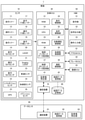
- FIG. 1 is a diagram showing a system configuration of the autonomous driving vehicle 1 of the embodiment.
- the automatic driving vehicle 1 of the present embodiment controls an overall ECU (Electronic Control Unit) 30 that performs automatic operation control, a sensor 10 that detects the state of the vehicle and the surrounding environment, and a vehicle device according to an instruction from the overall ECU 30. It includes various ECUs, an HMI (Human Machine Interface) 50 that is an interface with a driver, a communication device 70 that communicates with a data center 90, and a map data storage unit 80 that stores map data.
- ECU Electronic Control Unit
- HMI Human Machine Interface
- the HMI 50 has a display unit 51 that displays information to the driver, a voice output unit 52 that outputs voice, and an operation input unit 53 that accepts operation inputs by the driver and occupants.
- the sensor 10 includes a front sonar 11, a side sonar 12, a rear sonar 13, a front camera sensor 14, a side camera sensor 15, a rear camera sensor 16, and a front. It has a millimeter-wave radar 17, a lateral millimeter-wave radar 18, a rear millimeter-wave radar 19, a LiDAR 20, and an Imaging LiDAR 21. Further, the sensor 10 has a shift position sensor 22, a vehicle speed sensor 23, an acceleration sensor 24, and an ignition sensor 26 as sensors for detecting the state of the vehicle. Further, the sensor 10 has a GPS 25 for measuring the position of the vehicle.
- the self-driving vehicle 1 may be equipped with a sensor not shown in FIG.
- the overall ECU 30 includes a RAM 31, a CPU 32, a ROM 33, a display control unit 34, a voice control unit 35, a map upload data processing unit 36, a map download data processing unit 37, an acceleration control unit 38, and a speed control unit. It has 39 and an automatic operation control unit 40.
- the overall ECU 30 controls automatic driving, acquires parking-related data when the vehicle is parked, and transmits the acquired parking-related data to the data center 90.
- Parking-related data is data on the vehicle and its surroundings acquired when the vehicle is parked. In the first embodiment, the data is the position and orientation of the vehicle when parked.
- the entire ECU 30 corresponds to the control device.
- the display control unit 34 and the voice control unit 35 communicate with the HMI 50 and control the HMI 50 to realize a user interface with the driver.
- the acceleration control unit 38 and the speed control unit 39 communicate with the accelerator ECU 61 and the brake ECU 62 to control the accelerator and the brake.
- the map upload data processing unit 36 and the map download data processing unit 37 communicate with the data center 90 through the communication device 70, and upload and download the map data.
- the map download data processing unit 37 stores the received map data in the map data storage unit 80.
- the map data may be of any type, such as a high-precision map, a navigation map, or a map generated from probe data.
- the parking lot specifying unit 41 and the map data processing unit 42 will be described later.
- the data center 90 has a communication device 91, a map data processing unit 92, and a parking lot specifying unit 93.
- the data center 90 processes the map data uploaded from the vehicle by the map data processing unit 92, and updates the map data to the latest map data.
- the data center 90 distributes the latest map data to the vehicle in response to a request from the vehicle or periodically.
- the parking lot specifying unit 93 identifies a parking lot area by using parking-related data transmitted from a plurality of vehicles.
- FIG. 2 is a diagram showing a configuration of an application related to an embodiment.
- the application is realized by executing the program stored in the RAM 31 or the ROM 33 by the CPU 32.
- Such programs are also included within the scope of this disclosure.
- the overall ECU 30 has a parking determination unit 101, a parking-related data acquisition unit 102, and a parking-related data transmission unit 103 as functions related to processing of parking-related data.
- the parking determination unit 101 determines whether or not the vehicle has parked based on the data from the sensor 10 provided in the vehicle.
- the parking-related data acquisition unit 102 acquires parking-related data including data on the position and orientation of the parked vehicle when the parking determination unit 101 determines that the vehicle has been parked.
- the parking-related data transmission unit 103 transmits the parking-related data to the data center 90.
- the "time" in the embodiment may mean the timing, or may mean the case.
- the parking determination unit 101 determines whether or not the vehicle is parked based on the data from the ignition sensor 26 provided in the vehicle. When the parking determination unit 101 detects that the ignition key is off, it determines that the vehicle has parked.
- the parking-related data acquisition unit 102 acquires the position when the vehicle is parked and the direction of the vehicle as parking-related data. However, if the parked position is on the road, it will not be acquired as parking-related data. This is because when the parking position is on the road, it is considered that the vehicle has only temporarily parked on the road, and it is not a parking lot. Whether or not the parked position is on the road can be determined based on the map data stored in the map data storage unit 80 and the position of the own vehicle.
- the configuration may be such that the parking-related data is acquired and then not transmitted to the data center 90.
- the parking-related data transmission unit 103 transmits the acquired parking-related data to the data center 90. Specifically, the parking-related data transmission unit 103 instructs the communication device 70 to pass the parking-related data and transmit it to the data center 90. However, the parking-related data transmission unit 103 does not transmit the parking-related data to the data center 90 when the parking position is in a known parking lot area. The parking-related data is transmitted to the data center 90 in order to specify the parking lot area, and the parking-related data is unnecessary when the data center 90 is already known to be the parking lot area. In this case, the burden on the data center 90 can be reduced by not transmitting the parking-related data. While transmitting the parking-related data to the data center 90, the HMI 50 may notify the driver of the fact that the parking-related data is being transmitted.
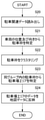
- FIG. 3 is a flowchart showing an operation in which the autonomous driving vehicle of the first embodiment transmits parking-related data.
- the overall ECU 30 mounted on the autonomous driving vehicle determines whether or not the ignition key is turned off based on the data from the ignition sensor 26 (S10). If the ignition key is not detected to be off (NO in S10), this process is repeated until the ignition key is detected to be off.
- the entire ECU 30 When the entire ECU 30 detects that the ignition key is off (YES in S10), it determines that the vehicle is parked and acquires data on the parking position of the vehicle and the orientation of the vehicle (S11). The overall ECU 30 reads out the map data from the map data storage unit 80, and determines whether or not the parking position is on the road (S12). If the parking position is on the road (YES in S12), the acquisition of parking-related data is terminated. When the parking position is not on the road (NO in S12), the entire ECU 30 acquires the data of the parking position and the orientation of the vehicle as parking-related data (S13).
- the overall ECU 30 determines whether or not the parking position related to the parking-related data is within the known parking lot area (S14). If the parking position is not within a known parking area (NO in S14), parking-related data is transmitted to the data center 90 (S15).
- the transmission timing may be (1) during the power latch period after the ignition is turned off, and (2) when the vehicle is started next time, but the transmission timing is not limited to these.
- the vehicle is equipped with the communication device 70, but when the vehicle is not equipped with the communication device 70, the data can be transmitted to the data center 90 to another vehicle or a parking lot. Parking-related data may be transmitted via the built-in infrastructure, a mobile terminal owned by the driver, and the like.
- the data center 90 receives the parking-related data transmitted from the vehicle (S16), and stores the received parking-related data (S17).
- FIG. 4 is a flowchart showing an operation of specifying a parking lot area based on the parking-related data received by the data center 90.
- the data center 90 acquires parking-related data from a large number of vehicles, the data center 90 identifies the parking lot area using the parking-related data.
- the timing for specifying the parking lot area may be periodic or may be when the collected parking-related data reaches a predetermined threshold value.
- the parking lot specifying unit 93 of the data center 90 reads parking-related data from the storage unit (S20), and specifies a parking frame from the parking position and the direction of the vehicle in the read parking-related data. For example, a rectangle having a length of 4 m and a width of 2 m is specified as a parking frame from the parking position and orientation (S21). Subsequently, the parking lot specifying unit 93 clusters the specified parking lots based on the positions of the parking lots (S22), and identifies the parking lot area by integrating the parking lots classified into the same group (S23). ).
- the parking lot specifying unit 93 adjusts the size of the parking lot based on the positional relationship of the parking lots classified into the same group. For example, if the parking frame is specified as a rectangle of 4 m in length ⁇ 2 m in width, but the adjacent parking frames are separated by 3 m, the parking frame is adjusted to be 4 m in length ⁇ 3 m in width.
- the parking lot specifying unit 93 reflects the data of the specified parking lot area in the map data (S24).
- the parking lot identification system of the first embodiment and the parking lot identification method have been described above.
- the entire ECU 30 provided in the vehicle acquires parking-related data including the parking position and the direction of the vehicle and transmits the parking-related data to the data center 90, and the data center 90 collects the parking-related data. Since the parking lot area is specified based on the above, the parking lot area can be specified accurately.
- the basic configuration of the parking lot specifying system of the second embodiment is the same as that of the parking lot specifying system of the first embodiment (see FIG. 1), but the parking lot specifying of the second embodiment is specified.
- the system uses the parking position and the direction of the vehicle as parking-related data, as well as the data of the traveling route of the vehicle when the vehicle takes a parking action.
- FIG. 5A and 5 (b) are diagrams showing an outline of the parking lot specifying system of the second embodiment.
- FIG. 5A shows a parking lot in which four parking frames are lined up in two rows, and shows a vehicle entering the parking lot from a public road, turning the vehicle back, and parking in the parking lot at the far left.
- FIG. 5B shows a parking lot in which four parking frames are lined up in a row, and shows a vehicle entering the parking lot from a public road, turning the vehicle back, and parking in the innermost parking frame.
- the parking lot area is specified based on the data of the parking position and the orientation of the vehicle, in the example shown in FIG. 5A, the parking lots in each row are not clustered into the same group and can be specified as two parking areas. There is sex. Further, in the example shown in FIG. 5B, the route on which the vehicle travels is not recognized as a parking lot area.
- the parking lot identification system according to the second embodiment can appropriately identify the passage in the parking lot area as the parking lot area by using the travel route data of the vehicle when the parking action is performed.
- the parking lot area does not mean only the parking frame for parking the vehicle, but also includes the passage for moving the vehicle to the parking frame. Parking areas also include, for example, areas such as the interior of a gated community where access is restricted by surrounding a residential area with a wall or a dead end in a residential area.
- the parking-related data acquisition unit 102 acquires the travel route data during the parking action.
- acquisition of travel route data in the second embodiment will be described.
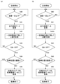
- FIG. 6A is a flowchart showing an operation of acquiring travel route data during parking behavior.
- the parking-related data acquisition unit 102 acquires the travel route data during the parking action, with the run between the time when the parking of the vehicle is detected and the time retroactive by a certain time as the parking action.
- the entire ECU 30 acquires the travel route data (S30), and overwrites and records the acquired travel route data, leaving up to the data before a certain period of time (S31).
- the overall ECU 30 determines whether or not the ignition key is turned off based on the data from the ignition sensor 26 (S32). If the ignition key is not detected to be turned off (NO in S32), the travel route data is continuously acquired and overwritten.
- the entire ECU 30 When the entire ECU 30 detects that the ignition key is off (YES in S32), it reads out the map data from the map data storage unit 80 and determines whether or not the parking position is on the road (S33). If the parking position is on the road (YES in S33), the acquisition of parking-related data is terminated. When the parking position is not on the road (NO in S33), the entire ECU 30 acquires the recorded travel route data for a certain period of time as parking-related data (S34).
- the data after a certain period of time is overwritten and erased, so that the storage capacity of the storage for storing the travel route data can be kept constant.
- FIG. 6B is a flowchart showing another example of the operation of acquiring the traveling route data during the parking action.
- the parking-related data acquisition unit 102 acquires the travel route data during the parking action, with the parking position from the parking position of the vehicle to the parking position by a certain distance as the parking action.
- the flow chart shown in FIG. 6 (b) is different from the flowchart shown in FIG. 6 (a) in that the overwrite recording does not leave the data up to a certain time before, but leaves the data up to a certain distance before. Is to do.
- the travel route data Based on the travel route data, the travel route data from the time when the vehicle is at a position separated by a predetermined distance from the current position to the current position overwrites the travel route data at the position separated by a predetermined distance or more (S31A).
- S31A predetermined distance or more
- FIG. 7A is an example of specifying the parking behavior by using the data of the traveling speed of the vehicle.
- the overall ECU 30 determines the vehicle speed based on the data from the vehicle speed sensor 23 (S40). When the speed of the vehicle is below a certain level (YES in S40), the overall ECU 30 acquires travel route data (S41 to S45) in the same manner as the flow (S30 to S34) described in FIG. 6A.
- FIG. 8A is a flowchart showing an example of specifying the parking behavior by using the shift position data as well.
- the overall ECU 30 determines the vehicle speed based on the data from the shift position sensor.
- the overall ECU 30 determines whether or not the shift position is “R” (back) (S50), and when the shift position is “R” (YES in S50), the flow described in FIG. 6A (a).
- the travel route data is acquired in the same manner as in S30 to S34) (S51 to S55). When the vehicle is backing, it is considered that the vehicle is parking. If the shift position is not "R” (NO in S50), the travel route data is not acquired.
- FIG. 8 (b) when the shift position is “R” (YES in S50), the entire ECU 30 travels in the same manner as the flow (S30 to S34) described in FIG. 6 (b). Acquire data (S51 to S55).
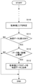
- FIG. 9 is a flowchart showing an example of acquiring travel route data as a parking behavior during a period in which parking support is being provided when parking is performed using the parking support function.
- the parking support function is a function that, when a parking target position is set, the parking support application calculates a route to the target position and guides the vehicle to the target position or supports the target position.
- the parking support function includes sensors 11, 12, 13, 14, 15, 16, 17, 18, 19, 20, 21 for guidance to the target position (for example, for detection of the parking frame used for guidance). Data from may be used.
- the parking support function may be such that the driver performs a part of steering control, accelerator control, brake control and peripheral monitoring, and the automatic parking function in which the vehicle automatically travels to the target position without the driver's operation. May be.
- the parking support function may be capable of searching and setting an empty parking frame as a target position without a driver's instruction by using, for example, at least one of the data from the camera sensors 14 and 16 and the map data. ..
- the parking support function may support parallel parking.
- the parking support function may be able to be turned on and off by an operation terminal such as a smartphone in the state of an unmanned vehicle in which the driver has moved from the inside of the vehicle to the outside of the vehicle, for example, for parking in a narrow space.
- the overall ECU 30 determines whether or not the parking support function is turned on by the automatic driving control unit 40 (S60). This determination is an example of determination as to whether or not the parking behavior of the vehicle is permitted.
- the entire ECU 30 records the travel route data until the ignition key is turned off (S61).
- the entire ECU 30 reads the map data from the map data storage unit 80, and determines whether or not the parking position is on the road. (S63). If the parking position is on the road (YES in S63), the acquisition of parking-related data is terminated.
- the entire ECU 30 acquires the recorded travel route data as parking-related data (S64). If the parking support function is automatically turned off when the vehicle completes parking, the travel route data is recorded until the parking support function is turned off in S61, and the ignition key is pressed after the parking support function is turned off. Before it is turned off, the processing up to S64 and the transmission of parking-related data from the vehicle to the data center 90 may be performed. Further, the traveling route and the target position scheduled to be automatically traveled may be transmitted from the vehicle to the data center 90 as parking-related data at the timing when the parking support function is turned on or while the parking support function is operating.
- FIG. 10 is a flowchart showing an operation of specifying a parking lot area based on the parking-related data received by the data center 90 of the second embodiment.
- the parking lot specifying unit 93 of the data center 90 reads out the parking-related data transmitted from the entire ECU 30 of each vehicle and accumulated from the storage unit (S70).
- the parking-related data includes the traveling route data during the parking behavior in addition to the parking position and the direction of the vehicle.
- the parking lot specifying unit 93 specifies a parking frame from the position and orientation of the vehicle (S71), and specifies the specified parking frame and the traveling route leading to the specified parking frame as a parking lot area (S72).
- the parking lot specifying unit 93 integrates the parking lot areas obtained from the individual parking lots to obtain the parking lot area (S73). In the present embodiment, the individual parking frames are connected via a traveling route, and the entire parking lot area is required.
- the parking lot specifying unit 93 reflects the obtained data of the parking lot area in the map data (S74).
- the parking lot identification system of the second embodiment identifies the parking lot area using the travel route data of the vehicle during the parking action, the parking lot is appropriately parked not only in the parking lot but also in the passage leading to the parking lot. You can ask for the parking area.
- the parking lot specifying system according to the third embodiment is the same as that of the parking lot identification system of the first embodiment (see FIG. 1), but the parking lot identification of the third embodiment is specified.
- the system uses not only the data of the parking frame parked by the vehicle but also the data of the parking frame obtained by image processing from the image taken by the vehicle as parking-related data.
- FIG. 11 is a flowchart showing an operation of acquiring the position and orientation of the parking frame as parking-related data by the entire ECU 30.
- the parking-related data acquisition unit 102 acquires video data from the front camera sensor 14, the side camera sensor 15, and the rear camera sensor 16 (S80). The video data may be acquired during the parking action.
- the parking-related data acquisition unit 102 extracts a parking frame from the acquired video data by image processing (S81).
- the extraction of the parking frame may be performed by pattern matching or by semantic segmentation of the image using the trained model.
- the parking-related data acquisition unit 102 specifies the position and orientation of the vehicle when the frame from which the parking frame is extracted is photographed, and extracts based on the position and orientation of the vehicle and the position in the image of the extracted parking frame.
- the position and orientation of the parking frame are specified (S82), and the data of the position and orientation of the parking frame is acquired as parking-related data (S83).
- S82 the position and orientation of the parking frame
- S83 the data of the position and orientation of the parking frame is acquired as parking-related data
- the size of the parking frame can also be acquired.
- the overall ECU 30 transmits not only the data of the parking frame in which the own vehicle is parked but also the data of other parking frames as parking-related data to the data center 90.
- the transmission of parking-related data is the same as that of the first embodiment, and is performed in the same manner as in steps S14 to S17 of the flowchart of FIG.
- the data center 90 identifies the parking lot area by using the parking frame data transmitted from the entire ECU 30 mounted on the vehicle.
- the parking lot identification system of the third embodiment also acquires data of other parking lots and sends the data to the data center 90, the parking lot even if the vehicle is not parked in all the parking lots in the parking lot area. It becomes possible to cover the data of parking lots in the area.
- the parking lot specifying system according to the fourth embodiment will be described.
- the basic configuration of the parking lot identification system of the fourth embodiment is the same as that of the parking lot identification system of the first embodiment (see FIG. 1), but the parking lot identification of the fourth embodiment is specified.
- the system uses off-road travel route data as parking-related data, in addition to parking position and vehicle orientation.
- the parking-related data acquisition unit 102 acquires the travel route data, compares the travel route with the map data stored in the map data storage unit 80, and the travel route is a road. When it is outside, the travel route data outside the road is acquired.
- the parking-related data transmission unit 103 transmits the travel route data outside the road and the parking position to the data center 90 as parking-related data.
- FIG. 12 is a flowchart showing an operation of acquiring parking-related data.
- the parking-related data acquisition unit 102 detects the traveling position of the vehicle with the GPS 25.
- the parking-related data acquisition unit 102 refers to the map data read from the map data storage unit 80, and determines whether or not the traveling position of the vehicle is off the road (S90). When the traveling position is on the road (NO in S90), it is repeatedly determined whether or not the traveling position is off the road.
- the parking-related data acquisition unit 102 acquires the traveling route data (S91).
- the parking-related data acquisition unit 102 determines whether or not the vehicle is parked (S92). When the vehicle is not parked (NO in S92), the parking-related data acquisition unit 102 continues to acquire the travel route data (S91).
- the parking-related data acquisition unit 102 acquires the travel locus and the parking position when traveling off the road as parking-related data (S93). If the vehicle traveling off the road returns to the road without parking, this flow may be terminated.
- FIG. 13 is a flowchart showing an operation of specifying a parking lot area based on the parking-related data received by the data center 90.
- the data center 90 acquires parking-related data from a large number of vehicles
- the data center 90 identifies the parking lot area using the parking-related data.
- the parking lot specifying unit 93 of the data center 90 reads parking-related data from the storage unit (S100), and uses the deviation point from the road as the entrance / exit of the parking lot based on the off-road travel route data which is one of the parking-related data.
- S101 storage unit
- FIG. 14 is a diagram showing a parking lot of a shopping mall on the side of the road.
- the thick lines in FIG. 14 are road links. Vehicles traveling on the road deviate from the road and enter this parking lot. Therefore, it is specified that the place where the vehicle deviates from the road and starts traveling off the road is the entrance / exit.
- the parking lot specifying unit 93 aligns the position of the vehicle at the doorway and the direction of the vehicle with respect to the parking lot-related data transmitted from each vehicle using the data of the specified doorway (S102).
- the position and direction data detected by GPS may differ from the actual data, but by aligning at the entrance and exit, it is possible to align the reference when superimposing the traveling trajectories of a large number of vehicles.
- the parking lot specifying unit 93 identifies the parking lot area based on the traveling locus outside the road and the parking frame (S103).
- the parking lot specifying unit 93 reflects the data of the specified parking lot area in the map data (S104).
- the parking lot specifying system of the fourth embodiment uses the traveling locus when traveling off the road as parking-related data, and identifies the deviation point to the outside of the road as the entrance / exit of the parking lot. This makes it possible to reflect on the map where the entrance / exit to the parking lot on the side of the road is. In addition, by aligning the vehicle at the doorway, the accuracy of specifying the parking area can be improved.
- the example of specifying the off-road travel in the vehicle and transmitting the travel locus of the off-road travel to the data center 90 as parking-related data has been given, but the off-road travel is detected in the data center 90. May be good.
- the vehicle may transmit the travel route data to the data center 90, and the data center 90 may collate the map data with the travel route to detect the vehicle traveling off the road.
- the position and direction of the vehicle at the entrance / exit are adjusted, but in addition to this, parking-related data collected from a large number of vehicles using feature data such as signs in the parking area. Alignment between data may be performed.
- the vehicle detects the feature detected from the images of the cameras 14 to 16 while traveling off the road, and acquires the data in the visible direction of the feature.
- the parking-related data transmission unit 103 transmits the feature and position data to the data center 90 as parking-related data.
- the data center 90 can specify the position of the feature based on the data from a large number of vehicles, and can align the reference when superimposing the travel locus data of each vehicle from the data in the visible direction of the specified feature. ..
- the parking lot specifying unit 93 may perform map matching using the travel locus uploaded from the vehicle to identify and update the entrance / exit and the parking lot area.
- the parking lot specifying system of the fifth embodiment is the same as that of the parking lot specifying system of the first embodiment.
- the parking lot identification system of the fifth embodiment has a predetermined standard. The map data is updated when it is satisfied.
- FIG. 15 is a diagram showing an operation in which the data center 90 specifies the parking lot area based on the parking-related data and then reflects the data of the specified parking lot area in the map data.
- the parking lot specifying unit 93 specifies the parking area (S110)
- the parking lot specifying unit 93 When there is a difference between the specified parking area and the map data (YES in S111), the parking lot specifying unit 93 has a predetermined threshold value obtained by dividing the number of data used for specifying the map area by the area of the specified parking area. It is determined whether or not it is the above (S112).
- the threshold value used here can be appropriately set according to the type of facility attached to the parking lot (for example, a shopping mall, a convenience store, etc.) and the size of the parking lot.
- the data used for specifying the parking area is the data of the position and orientation of the vehicle.
- the parking lot specifying unit 93 reflects the data of the parking lot area in the map data (S113). If (number of data / area) is not equal to or greater than a predetermined threshold value (NO in S112), the map data is not updated.
- the map data can be updated using reliable information. For example, if the parking lot area is large even if only the number of data is large, the parking lot is quiet and it may be difficult to accurately identify the parking lot area. For example, many people stop near the entrance of a store during the off-season on weekdays, and the vehicle is not parked in a place far from the store. In this case, the parking area is specified to be smaller than it actually is. According to the present embodiment, since the data in the state where the vehicle is parked at a predetermined density is used, the parking lot area can be appropriately specified.
- the method for determining the update timing described above is the second to fourth embodiments. It can be applied to any embodiment.
- the data used for determining the update timing is the number of data of the travel route data used for specifying the parking lot area.
- an example of determining whether or not to update using the value obtained by dividing the number of data by the area is given, but another index can be considered.
- the value obtained by dividing the number of data by the number of parking slots may be used as a reference.
- the usage ratio of the parking frame may be used as a reference. This is because when the parking lot is almost full, it is considered that the parking area can be accurately specified based on the parking position of the vehicle.
- the update that reflects the specified parking area in the map data has been described, but conversely, the map data may be updated even when the parking lot is exhausted or reduced. For example, it may be determined that the parking lot has disappeared when the vehicle entering the parking lot area continues to be in a state of being equal to or less than a predetermined threshold value for a predetermined period. Further, if the state of entering the parking area but not parking in a part of the area continues for a predetermined period, it may be determined that the part of the area is no longer a parking lot area.
- the parking lot identification system of the sixth embodiment uses the data of the parking lot area generated by the parking lot identification system of the fifth embodiment from the first embodiment, and uses the data of the parking lot area to drive the vehicle in the parking lot area.
- Acceleration suppression control is performed.
- the acceleration suppression control of the vehicle is a function called an erroneous step prevention function.
- acceleration suppression control is taken as an example, but speed suppression control may be performed.
- the vehicle on which the entire ECU 30 is mounted will be described as a vehicle having a driving assist function.
- the data center 90 downloads map data reflecting the parking lot area to the entire vehicle ECU 30, and the entire vehicle ECU 30 stores the downloaded map data in the map data storage unit 80.
- the overall ECU 30 limits the acceleration to a predetermined threshold value or less in order to prevent an accident due to an erroneous accelerator depression. This makes it possible to reduce the risk of accidentally stepping on the accelerator in the parking lot and colliding with a pedestrian or the like.
- the HMI 50 may notify the driver that the erroneous step prevention control is functioning or that the driver is in the erroneous step prevention area.
- the HMI 50 may also notify the driver that the vehicle is in the parking area.
- FIG. 16 is a diagram showing a state when a vehicle enters the parking lot.
- the inside of the parking lot area is an acceleration suppression area.
- the overall ECU 30 determines whether or not the vehicle is in the parking lot area, and if it is determined that the vehicle is in the parking lot area, controls so that the acceleration does not exceed a predetermined threshold value.
- the area R connecting the parking lot and the public road is provided near the entrance / exit of the parking lot, instead of suppressing or canceling the acceleration as soon as the boundary between the parking lot area and the public road is crossed. .. Whether or not the vehicle has entered the area R is determined by whether or not the vehicle is in the parking lot area and is at a predetermined distance from the outer edge of the parking lot area.
- the entire ECU 30 applies relaxed acceleration suppression.
- the restriction of acceleration suppression is released. The scene determination as to whether the vehicle is entering or participating can be made based on the traveling direction of the vehicle.
- the vehicle In the participation scene, by releasing the acceleration suppression when the vehicle is in the area R, the vehicle can smoothly go out on the public road and the risk of being hit by a vehicle behind the vehicle traveling on the public road can be reduced. Further, in the entrance scene, by applying a relaxed acceleration suppression when the vehicle is in the area R, it is possible to smoothly enter the parking lot while preventing an erroneous stepping.
- the area R has a size that includes the vehicle. This is because the accuracy of the sensor that detects the current position of the vehicle may not be high at the start of traveling. For example, positioning by GPS 25 may take time. In addition, since positioning by GPS25 is not possible in an indoor parking lot, the position of the vehicle is calculated from the position measured by GPS at the end by odometry such as wheel rotation amount and steering angle, but errors are accumulated and accuracy is accumulated. May not appear.
- the area R By setting the area R to a large value, it is possible to prevent the inconvenience that the acceleration is restricted even after the vehicle goes out on the public road. In the present embodiment, an example of limiting the acceleration in order to prevent erroneous stepping in the parking lot area has been described, but the speed may be limited instead of the acceleration.
- an example of determining whether the parking lot entrance scene or the parking lot entry scene is determined by whether the parking lot area is in front of or behind the vehicle is given, but the scene is determined in the front.
- the average speed of the vehicle traveling ahead is obtained from the image captured by the camera sensor 14, and it is determined whether or not the front is a public road based on whether or not the average speed of other vehicles is equal to or higher than a predetermined threshold value. May be good. If the front is a public road, it can be determined that the vehicle is about to enter the parking lot, and conversely, if the front is not a public road, it can be determined that the vehicle is about to enter the parking lot.
- an interface for canceling the erroneous step prevention function may be provided.
- an operation button for canceling the erroneous step prevention function by the operation of the driver or a voice release reception unit may be provided.
- the position or parking area where the acceleration suppression control is executed when the driver mistakenly steps on the vehicle and the acceleration suppression control actually works, the position or parking area where the acceleration suppression control is executed, the time (time stamp), and the version information of the map. It may be possible to memorize at least one of.
- the place for storing data may be an in-vehicle memory such as the map data storage unit 80, or a memory in the data center 90.
- landmark position data may be used as parking-related data.
- the position of the signboard is obtained, and the position data of the signboard (landmark) is transmitted to the data center 90 as parking-related data.
- the data center 90 can integrate the position data of the parking frame transmitted from a large number of vehicles with reference to the position data of the landmark.
- a parking completion flag indicating automatic parking or manual parking, and vehicle size or vehicle type data may be used as parking-related data.
- the position and orientation of the parking frame may be obtained by the entire ECU 30 mounted on the vehicle, and in that case, the data of the positions or centers and directions of the four corners of the parking frame may be used as parking-related data.
- data of the presence / absence of a traffic light at the entrance / exit of the parking lot, the presence / absence of a gate, the presence / absence of a sidewalk, the width of the sidewalk when there is a sidewalk, and the stop line near the entrance / exit may be used. These data can be obtained by analyzing the images taken by the cameras 14 to 16. By having such information as additional information in the parking lot area, it is possible to easily determine whether the accelerator erroneous step prevention function is ON / OFF in the parking lot. Further, data on whether or not the parking lot is a multi-story parking lot may be used. Whether it is a multi-storey car park or not can be determined by analyzing the video or from GPS data.
- the parking lot area can be specified based on the running history of the own vehicle.
- the place to park many times is, for example, a parking lot at home, a workplace, or a family hospital.
- the parking position and the slow-moving data before parking or the back data are stored in association with each other. Data with the same parking position is extracted, and the parking area is specified from the parking position and the driving data.
- the processing may be performed only by the own vehicle without transmitting to the data center. That is, the parking area may be specified by the parking lot specifying unit 41 of the entire ECU 30, and the specified parking area may be reflected in the map data by the map data processing unit 42.
- the parking lot identification system of the present disclosure is useful as a system for generating map data and the like.
Landscapes
- Engineering & Computer Science (AREA)
- Physics & Mathematics (AREA)
- General Physics & Mathematics (AREA)
- Automation & Control Theory (AREA)
- Transportation (AREA)
- Mechanical Engineering (AREA)
- Radar, Positioning & Navigation (AREA)
- Remote Sensing (AREA)
- Multimedia (AREA)
- Theoretical Computer Science (AREA)
- Chemical & Material Sciences (AREA)
- Analytical Chemistry (AREA)
- Mathematical Physics (AREA)
- Traffic Control Systems (AREA)
- Navigation (AREA)
Priority Applications (2)
| Application Number | Priority Date | Filing Date | Title |
|---|---|---|---|
| JP2022540043A JP7323074B2 (ja) | 2020-07-28 | 2021-06-03 | 駐車場特定システム、駐車場特定方法、制御装置、センタ装置、および駐車エリア特定方法 |
| US18/160,978 US12073722B2 (en) | 2020-07-28 | 2023-01-27 | Parking lot identification system and method |
Applications Claiming Priority (2)
| Application Number | Priority Date | Filing Date | Title |
|---|---|---|---|
| JP2020127449 | 2020-07-28 | ||
| JP2020-127449 | 2020-07-28 |
Related Child Applications (1)
| Application Number | Title | Priority Date | Filing Date |
|---|---|---|---|
| US18/160,978 Continuation US12073722B2 (en) | 2020-07-28 | 2023-01-27 | Parking lot identification system and method |
Publications (1)
| Publication Number | Publication Date |
|---|---|
| WO2022024547A1 true WO2022024547A1 (ja) | 2022-02-03 |
Family
ID=80035411
Family Applications (1)
| Application Number | Title | Priority Date | Filing Date |
|---|---|---|---|
| PCT/JP2021/021254 Ceased WO2022024547A1 (ja) | 2020-07-28 | 2021-06-03 | 駐車場特定システム、駐車場特定方法、制御装置、センタ装置、および駐車エリア特定方法 |
Country Status (3)
| Country | Link |
|---|---|
| US (1) | US12073722B2 (https=) |
| JP (1) | JP7323074B2 (https=) |
| WO (1) | WO2022024547A1 (https=) |
Cited By (3)
| Publication number | Priority date | Publication date | Assignee | Title |
|---|---|---|---|---|
| US20200279196A1 (en) * | 2018-01-10 | 2020-09-03 | Bayerische Motoren Werke Aktiengesellschaft | Parking Space Lock and System and Method for Providing Parking Service |
| CN117671989A (zh) * | 2022-08-27 | 2024-03-08 | 比亚迪股份有限公司 | 信息处理方法、服务器、泊车方法、泊车系统和车辆 |
| WO2024262409A1 (ja) * | 2023-06-21 | 2024-12-26 | 株式会社デンソー | 制御装置及び駐車場判定方法 |
Families Citing this family (8)
| Publication number | Priority date | Publication date | Assignee | Title |
|---|---|---|---|---|
| DE102018122992B4 (de) * | 2018-09-19 | 2021-10-14 | Volkswagen Aktiengesellschaft | Verfahren zum Bereitstellen von Positionsdaten von wenigstens einer Einfahrt zu einem Navigationsziel, Servereinrichtung zum Durchführen eines derartigen Verfahrens sowie Kraftfahrzeug |
| US12134399B2 (en) | 2021-10-22 | 2024-11-05 | Zoox, Inc. | Drivable surface map for autonomous vehicle navigation |
| US12025465B2 (en) * | 2021-10-22 | 2024-07-02 | Zoox, Inc. | Drivable surface map for autonomous vehicle navigation |
| US12145575B2 (en) * | 2021-12-22 | 2024-11-19 | Aptiv Technologies AG | Selection of a parking space using a probabilistic approach |
| JP7559777B2 (ja) * | 2022-01-14 | 2024-10-02 | トヨタ自動車株式会社 | 加速抑制装置 |
| JP7806274B2 (ja) * | 2022-09-05 | 2026-01-26 | 本田技研工業株式会社 | 駐車場区画推定装置及び駐車場区画推定方法 |
| US20250166507A1 (en) * | 2023-11-17 | 2025-05-22 | Fca Us Llc | Method for recording a parking location of a vehicle |
| US20250349130A1 (en) * | 2024-05-09 | 2025-11-13 | GM Global Technology Operations LLC | Mapping for vehicle parking |
Citations (2)
| Publication number | Priority date | Publication date | Assignee | Title |
|---|---|---|---|---|
| JP2010025860A (ja) * | 2008-07-23 | 2010-02-04 | Aisin Aw Co Ltd | 駐車場検出装置、駐車場検出方法及びコンピュータプログラム |
| WO2019244537A1 (ja) * | 2018-06-20 | 2019-12-26 | クラリオン株式会社 | 駐車支援システム及び駐車支援装置 |
Family Cites Families (6)
| Publication number | Priority date | Publication date | Assignee | Title |
|---|---|---|---|---|
| US7899583B2 (en) * | 2005-04-12 | 2011-03-01 | Ehud Mendelson | System and method of detecting and navigating to empty parking spaces |
| US10043388B1 (en) * | 2013-05-29 | 2018-08-07 | Dp Technologies, Inc. | Parking system |
| JP2018181024A (ja) | 2017-04-17 | 2018-11-15 | 本田技研工業株式会社 | 駐車場推定装置及び駐車場推定方法 |
| WO2019065328A1 (ja) | 2017-09-28 | 2019-04-04 | 本田技研工業株式会社 | 駐車場推定装置及び駐車場推定方法 |
| JP2020067704A (ja) * | 2018-10-22 | 2020-04-30 | アイシン・エィ・ダブリュ株式会社 | 駐車場特定システムおよび駐車場特定プログラム |
| WO2022201722A1 (ja) * | 2021-03-25 | 2022-09-29 | パナソニックIpマネジメント株式会社 | 情報表示プログラム、情報表示装置および情報表示方法 |
-
2021
- 2021-06-03 JP JP2022540043A patent/JP7323074B2/ja active Active
- 2021-06-03 WO PCT/JP2021/021254 patent/WO2022024547A1/ja not_active Ceased
-
2023
- 2023-01-27 US US18/160,978 patent/US12073722B2/en active Active
Patent Citations (2)
| Publication number | Priority date | Publication date | Assignee | Title |
|---|---|---|---|---|
| JP2010025860A (ja) * | 2008-07-23 | 2010-02-04 | Aisin Aw Co Ltd | 駐車場検出装置、駐車場検出方法及びコンピュータプログラム |
| WO2019244537A1 (ja) * | 2018-06-20 | 2019-12-26 | クラリオン株式会社 | 駐車支援システム及び駐車支援装置 |
Cited By (5)
| Publication number | Priority date | Publication date | Assignee | Title |
|---|---|---|---|---|
| US20200279196A1 (en) * | 2018-01-10 | 2020-09-03 | Bayerische Motoren Werke Aktiengesellschaft | Parking Space Lock and System and Method for Providing Parking Service |
| US11790283B2 (en) * | 2018-01-10 | 2023-10-17 | Bayerische Motoren Werke Aktiengesellschaft | Parking space lock and system and method for providing parking service |
| CN117671989A (zh) * | 2022-08-27 | 2024-03-08 | 比亚迪股份有限公司 | 信息处理方法、服务器、泊车方法、泊车系统和车辆 |
| WO2024262409A1 (ja) * | 2023-06-21 | 2024-12-26 | 株式会社デンソー | 制御装置及び駐車場判定方法 |
| JPWO2024262409A1 (https=) * | 2023-06-21 | 2024-12-26 |
Also Published As
| Publication number | Publication date |
|---|---|
| US12073722B2 (en) | 2024-08-27 |
| JP7323074B2 (ja) | 2023-08-08 |
| JPWO2022024547A1 (https=) | 2022-02-03 |
| US20230169861A1 (en) | 2023-06-01 |
Similar Documents
| Publication | Publication Date | Title |
|---|---|---|
| JP7323074B2 (ja) | 駐車場特定システム、駐車場特定方法、制御装置、センタ装置、および駐車エリア特定方法 | |
| US20200361462A1 (en) | Vehicle control device, terminal device, parking lot management device, vehicle control method, and storage medium | |
| CN111063202B (zh) | 一种基于电子地图的智能泊车管理方法 | |
| CN110562248B (zh) | 一种基于无人机的自动泊车系统及自动泊车方法 | |
| US20200387153A1 (en) | Parking lot management system, parking lot management device, parking lot management method, and storage medium | |
| JP6926976B2 (ja) | 駐車支援装置及びコンピュータプログラム | |
| CN110329245A (zh) | 一种自动泊车方法、装置、设备和车辆 | |
| US11345365B2 (en) | Control device, getting-into/out facility, control method, and storage medium | |
| WO2024002215A1 (zh) | 一种确定停车位置的方法和装置 | |
| US11370418B2 (en) | Parking assist system and parking assist device | |
| CN107097782A (zh) | 用于求取车辆数据的方法和系统与相应的车辆、停车场 | |
| US11400921B2 (en) | Vehicle control device, vehicle control method, and storage medium | |
| CN115009267B (zh) | 自动泊车系统、自动泊车系统的控制方法及自动驾驶车辆 | |
| CN116508083B (zh) | 停车辅助方法及停车辅助装置 | |
| CN114973644A (zh) | 道路信息生成装置 | |
| JP2020166665A (ja) | 車両経路管理方法、車両経路管理装置、及び車両経路管理システム | |
| JP2020107212A (ja) | 車両制御システム、車両制御方法、及びプログラム | |
| CN115472037B (zh) | 一种基于场端定位的辅助泊车方法 | |
| CN115158322A (zh) | 地图信息生成装置及本车位置推定装置 | |
| US11113968B2 (en) | Method for mobile parking assistance | |
| JP2018122789A (ja) | 運転支援装置、運転支援システムおよび運転支援方法 | |
| JP2022175719A (ja) | 自動駐車サーバ、自動運転車両、自動駐車システム | |
| CN113470417A (zh) | 收容区域管理装置 | |
| CN115035707A (zh) | 自动泊车系统及自动泊车系统的控制方法 | |
| CN112614379A (zh) | 自主泊车导航的方法和装置 |
Legal Events
| Date | Code | Title | Description |
|---|---|---|---|
| 121 | Ep: the epo has been informed by wipo that ep was designated in this application |
Ref document number: 21850912 Country of ref document: EP Kind code of ref document: A1 |
|
| ENP | Entry into the national phase |
Ref document number: 2022540043 Country of ref document: JP Kind code of ref document: A |
|
| NENP | Non-entry into the national phase |
Ref country code: DE |
|
| 122 | Ep: pct application non-entry in european phase |
Ref document number: 21850912 Country of ref document: EP Kind code of ref document: A1 |