WO2022024543A1 - 製造工程管理システム、製造工程管理装置、製造工程管理方法、及びプログラム - Google Patents
製造工程管理システム、製造工程管理装置、製造工程管理方法、及びプログラム Download PDFInfo
- Publication number
- WO2022024543A1 WO2022024543A1 PCT/JP2021/020842 JP2021020842W WO2022024543A1 WO 2022024543 A1 WO2022024543 A1 WO 2022024543A1 JP 2021020842 W JP2021020842 W JP 2021020842W WO 2022024543 A1 WO2022024543 A1 WO 2022024543A1
- Authority
- WO
- WIPO (PCT)
- Prior art keywords
- product
- manufacturing process
- acceleration
- tension
- process control
- Prior art date
Links
Images


Classifications
-
- G—PHYSICS
- G05—CONTROLLING; REGULATING
- G05B—CONTROL OR REGULATING SYSTEMS IN GENERAL; FUNCTIONAL ELEMENTS OF SUCH SYSTEMS; MONITORING OR TESTING ARRANGEMENTS FOR SUCH SYSTEMS OR ELEMENTS
- G05B19/00—Programme-control systems
- G05B19/02—Programme-control systems electric
- G05B19/418—Total factory control, i.e. centrally controlling a plurality of machines, e.g. direct or distributed numerical control [DNC], flexible manufacturing systems [FMS], integrated manufacturing systems [IMS], computer integrated manufacturing [CIM]
- G05B19/41875—Total factory control, i.e. centrally controlling a plurality of machines, e.g. direct or distributed numerical control [DNC], flexible manufacturing systems [FMS], integrated manufacturing systems [IMS], computer integrated manufacturing [CIM] characterised by quality surveillance of production
-
- G—PHYSICS
- G01—MEASURING; TESTING
- G01L—MEASURING FORCE, STRESS, TORQUE, WORK, MECHANICAL POWER, MECHANICAL EFFICIENCY, OR FLUID PRESSURE
- G01L5/00—Apparatus for, or methods of, measuring force, work, mechanical power, or torque, specially adapted for specific purposes
- G01L5/04—Apparatus for, or methods of, measuring force, work, mechanical power, or torque, specially adapted for specific purposes for measuring tension in flexible members, e.g. ropes, cables, wires, threads, belts or bands
- G01L5/10—Apparatus for, or methods of, measuring force, work, mechanical power, or torque, specially adapted for specific purposes for measuring tension in flexible members, e.g. ropes, cables, wires, threads, belts or bands using electrical means
-
- D—TEXTILES; PAPER
- D01—NATURAL OR MAN-MADE THREADS OR FIBRES; SPINNING
- D01D—MECHANICAL METHODS OR APPARATUS IN THE MANUFACTURE OF ARTIFICIAL FILAMENTS, THREADS, FIBRES, BRISTLES OR RIBBONS
- D01D10/00—Physical treatment of artificial filaments or the like during manufacture, i.e. during a continuous production process before the filaments have been collected
- D01D10/04—Supporting filaments or the like during their treatment
- D01D10/0436—Supporting filaments or the like during their treatment while in continuous movement
-
- D—TEXTILES; PAPER
- D01—NATURAL OR MAN-MADE THREADS OR FIBRES; SPINNING
- D01D—MECHANICAL METHODS OR APPARATUS IN THE MANUFACTURE OF ARTIFICIAL FILAMENTS, THREADS, FIBRES, BRISTLES OR RIBBONS
- D01D5/00—Formation of filaments, threads, or the like
- D01D5/12—Stretch-spinning methods
- D01D5/16—Stretch-spinning methods using rollers, or like mechanical devices, e.g. snubbing pins
-
- G—PHYSICS
- G05—CONTROLLING; REGULATING
- G05B—CONTROL OR REGULATING SYSTEMS IN GENERAL; FUNCTIONAL ELEMENTS OF SUCH SYSTEMS; MONITORING OR TESTING ARRANGEMENTS FOR SUCH SYSTEMS OR ELEMENTS
- G05B2219/00—Program-control systems
- G05B2219/30—Nc systems
- G05B2219/32—Operator till task planning
- G05B2219/32368—Quality control
-
- Y—GENERAL TAGGING OF NEW TECHNOLOGICAL DEVELOPMENTS; GENERAL TAGGING OF CROSS-SECTIONAL TECHNOLOGIES SPANNING OVER SEVERAL SECTIONS OF THE IPC; TECHNICAL SUBJECTS COVERED BY FORMER USPC CROSS-REFERENCE ART COLLECTIONS [XRACs] AND DIGESTS
- Y02—TECHNOLOGIES OR APPLICATIONS FOR MITIGATION OR ADAPTATION AGAINST CLIMATE CHANGE
- Y02P—CLIMATE CHANGE MITIGATION TECHNOLOGIES IN THE PRODUCTION OR PROCESSING OF GOODS
- Y02P90/00—Enabling technologies with a potential contribution to greenhouse gas [GHG] emissions mitigation
- Y02P90/02—Total factory control, e.g. smart factories, flexible manufacturing systems [FMS] or integrated manufacturing systems [IMS]
Definitions
- the present invention relates to a tension measuring method applied to a product to be manufactured, which is used in a process of molding a sheet, a film, a fiber, etc., and a management device thereof, and in particular, a tension of a thread in a spinning process of a synthetic resin fiber.
- the present invention relates to measurement at an arbitrary position in a non-contact state, a manufacturing process control system, a manufacturing process control device, a manufacturing process management method, and a program.
- the production process includes a molding process involving large deformation of the resin using a roll, for example, a process of forming a film into a thin film of the resin, a process of spinning the resin discharged from the spinning nozzle, and the like. It has been known. It is known that the history of deformation applied in such a process is stored in the resin as residual strain and strongly affects product quality and processing stability, but due to physical restrictions and economic restrictions, it is known. In many cases, the introduction of sensing technology is postponed. In the process, shrinkage stress is generated due to the relaxation of residual strain, which can be detected as the tension of the product to be manufactured.
- the tension applied to the web is directly measured and measured by a sensor device in the processing process of the web, which is a strip-shaped or thread-shaped member made of a resin such as plastic, cloth, paper, metal, or the like.
- a sensor device in the processing process of the web, which is a strip-shaped or thread-shaped member made of a resin such as plastic, cloth, paper, metal, or the like.
- Patent Document 2 relates to a system that monitors changes in tension vibration in the frequency domain by performing a high-speed Fourier transform on the acquired tension of the yarn, and controls and manages the abnormality of the yarn and the quality of the processed yarn. The technology is disclosed.
- Patent Document 3 describes a technique relating to a measuring method and an apparatus for irradiating a small amount of yarn with infrared rays and detecting the yarn tension from transmitted light in order to detect the tension of the yarn in a non-contact manner. Is disclosed.
- Patent Document 4 describes a technique relating to a method of applying vibration to a belt, acquiring the vibration at that time by an acceleration sensor, obtaining a natural frequency by Fourier transforming the vibration, and calculating the belt tension from the obtained vibration frequency. It has been disclosed.
- the tension is calculated by obtaining the frequency from the vibration of the target of tension monitoring instead of directly measuring the tension as in Patent Document 4, the vibration to the target of tension monitoring is added and detected.
- Prior work is required, such as calculating the natural frequency from the change in acceleration and identifying whether or not the natural frequency is due to the vibration of the belt.
- an object of the present invention is to provide a manufacturing process management system, a manufacturing process management device, a manufacturing process management method, and a program capable of easily performing manufacturing process management.
- the manufacturing process control system is in contact with a work piece that moves under tension, and a support member that supports the work piece and the support. It includes an acquisition unit for acquiring information on the dispersion of the mechanical fluctuation based on the mechanical fluctuation of the member, and an estimation unit for estimating the tension applied to the product to be manufactured.
- the manufacturing process control device comes into contact with a product to be moved under tension, and the mechanical fluctuation is based on the mechanical fluctuation of the support member that supports the product. It is provided with an acquisition unit for acquiring information on the dispersion of the product and an estimation unit for estimating the tension applied to the product to be manufactured.
- the acquisition unit comes into contact with a work piece that moves under tension, and is based on the mechanical fluctuation of the support member that supports the work piece. It includes acquiring information about the dispersion of mechanical fluctuations and estimating the tension applied to the work piece by the estimation unit.
- the program according to one aspect of the present invention brings the computer into contact with a product to be moved under tension, and the mechanical fluctuation is based on the mechanical fluctuation of the support member that supports the product. It functions as an acquisition unit for acquiring information on the dispersion of the product and an estimation unit for estimating the tension applied to the product to be manufactured.
- manufacturing process control can be easily performed.
- FIG. 1 shows X-axis, Y-axis, and Z-axis (spatial axes) that are orthogonal to each other as needed.
- the direction in which the arrow extends is referred to as "positive direction”
- the direction opposite to the positive direction is referred to as "negative direction”.
- FIG. 1 is a diagram showing an example of a manufacturing process of a product to be manufactured according to an embodiment of the present invention.
- FIG. 1 shows a molding process in which the workpiece 2 is molded as an example of the manufacturing process.
- the present invention will be described by taking control of the molding process of the product 2 as an example.
- the product 2 is, for example, a fibrous synthetic resin.
- the synthetic resin is a thermoplastic resin having thermoplasticity.
- a synthetic resin is processed in a molding process to produce a processed resin product such as a film, a sheet, or a fiber.
- the resin processed product produced from the synthetic resin will be described as the product to be manufactured 2.
- a plurality of rolls 3 are provided.
- the roll 3 is an example of the support member according to the present embodiment.
- the roll 3 comes into contact with the work piece 2 moving under tension and supports the work piece 2.
- the number and arrangement of the rolls 3 provided in the molding process is not limited to the example shown in FIG.
- the roll 3 rotates around the roll shaft 4.
- the resin processed product is arranged so as to be in contact with the roll 3.
- the resin processed product repeats movement in the positive or negative direction of the Y-axis and movement in the positive direction of the Z-axis while being molded (for example, elongated) by the rotation of the roll 3. As a result, the processed resin product is moved from the upstream process to the downstream process.
- the resin processed product and the roll 3 are brought into contact with each other so that the shape of the resin processed product when viewed from the X-axis direction is U-shaped.
- the method of contacting the processed resin product with the roll 3 is not limited to the example shown in FIG. The method of contacting the resin processed product with the roll 3 may change depending on the arrangement of the roll 3.
- FIG. 2 is a diagram showing an example of the configuration of the roll device according to the embodiment of the present invention.
- the roll device 10 includes a roll 3, a roll shaft 4, a roll bearing 5, and an acceleration sensor 6.
- the roll 3 is connected to the roll bearing 5 via the roll shaft 4.
- the roll device 10 is provided with a sensor device for detecting the measured value on the roll 3.
- the sensor device is an acceleration sensor 6. Not only is the acceleration sensor 6 easy to install in existing equipment, but it can also be installed in places where it was difficult to install a tension sensor due to restrictions such as high process temperature.
- the accelerometer 6 is attached to the roll device 10.
- the accelerometer 6 is attached to the upper part of the roll bearing 5 (region 7 shown in FIG. 2).
- the acceleration sensor 6 may be attached to another position of the roll bearing 5, or may be any other position as long as the vibration of the roll 3 or the roll shaft 4 can be detected. Further, a plurality of acceleration sensors 6 may be attached to one roll bearing 5.
- the acceleration sensor 6 detects the acceleration according to the rotational power of the roll 3.
- the acceleration sensor 6 for example, a sensor capable of detecting acceleration in three axial directions is used.
- the manufacturing process control system calculates the variance of the detected acceleration (an example of mechanical fluctuation), and estimates the tension applied to the resin processed product based on the calculated variance.
- the manufacturing process control system is not limited to this, and tension may be estimated based on velocity or position dispersion instead of acceleration.
- the acceleration, velocity or position for estimating the tension is one in which positive and negative values are repeated (mechanical fluctuation) with reference to the measured value when the tension is not applied when the tension is applied.
- the acceleration in the direction in which the fluctuation of the tension applied to the resin processed product most strongly acts on the fluctuation of the acceleration that is, the acceleration in one axial direction. Acceleration only) is used to estimate the tension applied to the processed resin product.
- process conditions may be added to the detection of mechanical fluctuations.
- the process conditions are conditions set in the molding process, for example, the temperature and the production speed related to the physical properties of the resin processed product.
- the process conditions have a great influence on the residual strain and shrinkage stress in the processed resin product. Residual strain and shrinkage stress affect the tension applied to the processed resin product. Therefore, by adding the process conditions to the detection of mechanical fluctuations, the tension applied to the processed resin product can be estimated with higher accuracy. Further, in order to obtain physical property information on a pure resin, mechanical fluctuations may be obtained in consideration of process conditions.
- FIG. 3 is a block diagram showing an example of the functional configuration of the manufacturing process control system according to the embodiment of the present invention.
- the manufacturing process control system 1 includes a roll device 10 and a manufacturing process control device 20.
- the roll device 10 is a device that performs processing such as stretching on a resin processed product. As shown in FIG. 3, the roll device 10 has a sensor unit 110 and a drive unit 120.
- the sensor unit 110 has a function of detecting the measured value in the roll 3.
- the function of the sensor unit 110 is realized by the acceleration sensor 6.
- the sensor unit 110 transmits the acceleration corresponding to the rotational power of the roll 3 detected by the acceleration sensor 6 to the manufacturing process control device 20.
- the drive unit 120 has a function of driving the roll device 10.
- the function of the drive unit 120 is realized by a motor.
- the operation of the drive unit 120 is controlled by the manufacturing process control device 20.
- the manufacturing process management device 20 is a device that controls the operation of the roll device 10 to control the molding process of the resin processed product.
- the manufacturing process management device 20 is realized by, for example, a PC (Personal Computer), a smartphone, a tablet terminal, a server terminal, or the like.
- the manufacturing process control device 20 has a communication unit 210, a control unit 220, and a storage unit 230.
- the communication unit 210 has a function of transmitting and receiving various information.
- the communication unit 210 transmits the control information input from the control unit 220 to the roll device 10.
- the control information is, for example, information for controlling the operation of the drive unit 120 of the roll device 10.
- the communication unit 210 receives the acceleration transmitted from the sensor unit 110 of the roll device 10 and inputs the received acceleration to the control unit 220.
- the communication in the communication unit 210 is performed by wireless communication.
- Control unit 220 has a function of controlling the overall operation of the manufacturing process control device 20.
- the control unit 220 is realized, for example, by causing a CPU (Central Processing Unit) provided as hardware in the manufacturing process management device 20 to execute a program.
- a CPU Central Processing Unit
- control unit 220 includes an acquisition unit 2202, a calculation unit 2204, an estimation unit 2206, a determination unit 2208, and a condition control unit 2210.
- the acquisition unit 2202 acquires the acceleration.
- the acquisition unit 2202 acquires the acceleration received by the communication unit 210 from the sensor unit 110 of the roll device 10.
- the acquisition unit 2202 inputs the acquired acceleration to the calculation unit 2204.
- the acceleration acquired by the acquisition unit 2202 is an example of information regarding the variance of the mechanical fluctuation. The information is not limited to acceleration.
- (2-2) Calculation unit 2204 The calculation unit 2204 calculates the variance of the acceleration based on the acceleration in the roll 3. The calculation unit 2204 calculates the variance of the acceleration based on the acceleration input from the acquisition unit 2202. The calculation unit 2204 inputs information indicating the calculated variance of the acceleration (hereinafter, also referred to as “variance information”) to the estimation unit 2206.
- the calculation unit 2204 calculates the standard deviation as a variance based on the measurement result (6000 points) measured by the acceleration sensor 6 for 1 minute.
- the acceleration measurement cycle by the acceleration sensor 6 is not limited to this example.
- the acceleration measurement cycle of the accelerometer 6 may be appropriately changed, for example, according to the accuracy required for tension estimation.
- Estimating unit 2206 The estimation unit 2206 estimates the tension applied to the processed resin product. For example, the estimation unit 2206 estimates the tension applied to the resin processed product based on the dispersion information input from the calculation unit 2204. Specifically, the estimation unit 2206 estimates the tension applied to the resin processed product based on the correlation between the dispersion information and the tension applied to the resin processed product. The estimation unit 2206 inputs information indicating the estimated tension (hereinafter, also referred to as “estimation information”) to the determination unit 2208.
- the estimation unit 2206 is based on the correlation between the fluctuation of the dispersion of acceleration and the fluctuation of the tension applied to the resin processed product on the tension direction axis determined by the direction of the tension received by the roll 3 from the resin processed product. Estimate the fluctuation of tension applied to the processed resin product.
- the estimation unit 2206 can easily estimate the fluctuation of the tension applied to the processed resin product by using the correlation.
- the correlation between the dispersion of acceleration and the tension can be either a correlation (positive correlation) or an inverse correlation (negative correlation) depending on the magnitude of tension.
- the roll 3 may vibrate in all directions.
- the roll 3 rotates while the resin processed product is supported by the roll 3, so that the resin processed product moves from the upstream process to the downstream process while being molded.
- the tension applied to the resin processed product is weak, the vibration in the roll 3 is pulled in the direction parallel to the resin processed product according to the tension. That is, when the tension increases, the vibration (acceleration) also increases, and when the tension decreases, the vibration (acceleration) also decreases.
- the dispersion of acceleration and the tension have a correlation.
- the vibration in the roll 3 is suppressed in the direction parallel to the resin processed product according to the tension. That is, when the tension increases, the vibration (acceleration) decreases, and when the tension decreases, the vibration (acceleration) increases. Therefore, when the tension applied to the processed resin product is strong, the dispersion of acceleration and the tension have an inverse correlation.
- the dispersion of acceleration and the tension have an inverse correlation.
- the correlation between the fluctuation of the dispersion of the acceleration in the roll 3 and the fluctuation of the tension applied to the resin processed product on the tension direction axis is an inverse correlation. Therefore, the estimation unit 2206 estimates that the fluctuation of the tension applied to the processed resin product tends to decrease when the fluctuation of the dispersion of the acceleration tends to increase. On the other hand, the estimation unit 2206 estimates that when the fluctuation of the dispersion of acceleration tends to decrease, the fluctuation of the tension applied to the processed resin product tends to increase.
- the correlation with the axis having the largest fluctuation in acceleration can be the largest.
- the relationship between the dispersion of acceleration and the fluctuation of tension in the present embodiment is not limited to the inverse correlation relationship, and may be a correlation relationship.
- the estimation unit 2206 may estimate the tension applied to the resin processed product based on at least one process condition of the resin processed product.
- the process conditions are, for example, the process temperature or the production rate of the processed resin product.
- the estimation unit 2206 can estimate the tension in the resin processed product in consideration of the residual strain and the shrinkage stress. Therefore, the estimation unit 2206 can improve the estimation accuracy of the tension applied to the resin processed product.
- the determination unit 2208 determines the state of the resin processed product based on the estimated tension applied to the resin processed product. For example, the determination unit 2208 determines the state of the resin processed product based on the estimation information input from the estimation unit 2206. The determination unit 2208 inputs the determination result of the state of the resin processed product to the condition control unit 2210.
- the determination unit 2208 determines that the state of the processed resin product is good.
- a state in which the fluctuation of tension is stable there is a state in which the difference between the fluctuation of tension indicated by the estimated information input last time and the fluctuation of tension indicated by the estimated information input this time is less than a predetermined threshold value. ..
- the determination unit 2208 determines that the state of the processed resin product is abnormal.
- a state in which the fluctuation of tension is unstable there is a state in which the difference between the fluctuation of tension indicated by the estimated information input last time and the fluctuation of tension indicated by the estimated information input this time is equal to or more than a predetermined threshold value.
- a state in which the difference is equal to or higher than a predetermined threshold value is a state in which the fluctuation of tension suddenly increases or decreases.
- Factors that cause the fluctuation of tension to become unstable include, for example, the resin processed product being wound around the roll 3 and the resin processed product being cut.
- the determination unit 2208 can determine the position of the resin processed product in an abnormal state. For example, the determination unit 2208 identifies the acceleration sensor 6 that has detected the acceleration that is the source of the estimation information used for determining the state of the resin processed product. As a result, the determination unit 2208 can grasp that the state of the resin processed product is abnormal in the roll device 10 provided with the specified acceleration sensor 6.
- Condition control unit 2210 controls the process conditions of the resin processed product according to the state of the resin processed product. For example, the condition control unit 2210 changes the process conditions of the resin processed product according to the determination result input from the determination unit 2208. The condition control unit 2210 transmits control information indicating the changed process conditions to the drive unit 120 of the roll device 10 via the communication unit 210.
- the condition control unit 2210 changes the process conditions of the processed resin product according to the state of the processed resin product. For example, the condition control unit 2210 slows down the production speed of the processed resin product.
- the magnitude of the tension applied to the resin processed product can increase as the production speed increases. Therefore, the condition control unit 2210 can reduce the magnitude of the tension applied to the resin processed product by slowing down the production speed.
- condition control unit 2210 accelerates the production speed of the processed resin product.
- the condition control unit 2210 accelerates the production speed to the extent that the state of the processed resin product does not become abnormal. As a result, the condition control unit 2210 can improve the productivity of the processed resin product.
- the storage unit 230 has a function of storing various types of information.
- the storage unit 230 may be a storage medium, for example, an HDD (Hard Disk Drive), a flash memory, an EEPROM (Electrically Erasable Programmable Read Only Memory), a RAM (Random Access Read / Write Memory), or a RAM (Random Access read / writer) It consists of any combination of storage media.
- a non-volatile memory can be used for the storage unit 230.
- FIG. 4 is a flowchart showing a processing flow in the manufacturing process control system 1 according to the present embodiment.
- the manufacturing process control system 1 acquires the acceleration in the resin processed product (S102). Specifically, the sensor unit 110 (accelerometer 6) of the roll device 10 detects the acceleration in the resin processed product. The sensor unit 110 transmits the detected acceleration to the manufacturing process control device 20. The acquisition unit 2202 of the manufacturing process control device 20 acquires the acceleration transmitted from the sensor unit 110 via the communication unit 210.
- the manufacturing process control system 1 calculates the variance of the acceleration (S104). Specifically, the calculation unit 2204 of the manufacturing process management device 20 calculates the dispersion information indicating the variance of the acceleration based on the acceleration acquired by the acquisition unit 2202.
- the manufacturing process control system 1 estimates the tension applied to the processed resin product (S106). Specifically, the estimation unit 2206 of the manufacturing process control device 20 estimates the estimation information indicating the tension applied to the resin processed product based on the correlation between the dispersion information calculated by the calculation unit 2204 and the tension.
- the manufacturing process control system 1 determines the state of the processed resin product (S108). Specifically, the determination unit 2208 of the manufacturing process control device 20 determines the state of the resin processed product based on the estimation information estimated by the estimation unit 2206.
- the manufacturing process control system 1 controls the process conditions (S110). Specifically, the condition control unit 2210 of the manufacturing process management device 20 controls the process conditions based on the determination result determined by the determination unit 2208. After controlling the process conditions, the manufacturing process control system 1 may repeat the process from S102.
- the manufacturing process control system 1 has a roll 3 that comes into contact with a resin processed product that moves under tension and supports the resin processed product.
- the manufacturing process control system 1 calculates the variance of the acceleration based on the acceleration in the roll 3.
- the manufacturing process control system 1 estimates the tension applied to the processed resin product.
- the manufacturing process control system 1 estimates the tension applied to the resin processed product based on the acceleration of the roll 3 in contact with the resin processed product.
- the manufacturing process control system 1 can easily estimate the tension applied to the resin processed product without using a tension sensor. That is, even in equipment where it is difficult to introduce a tension sensor, the tension applied to the roll 3 can be easily estimated by using the sensor device (accelerometer 6) capable of detecting the acceleration on the roll 3.
- the manufacturing process management system 1 can easily manage the manufacturing process.
- Example> In the embodiment according to the embodiment of the present invention, the tension applied to the resin processed product measured by using the tension sensor and the variance (standard deviation) of the acceleration calculated from the acceleration in the roll device 10 measured by using the acceleration sensor 6 are used. To compare. This confirms that there is a correlation between the tension applied to the processed resin product and the dispersion of acceleration in the roll device 10.
- the tension sensor may be provided at any position as long as the tension propagating from the roll 3 can be measured.
- the roll 3 in the process (see FIG. 1) in which the resin processed product is U-shaped with respect to the roll 3 is set as the roll to be installed on the acceleration sensor 6.
- the specific installation position of the acceleration sensor 6 is the upper part (region 7) of the roll bearing 5 shown in FIG.
- the direction of the acceleration measured by the acceleration sensor 6 is the direction in which the fluctuation of the tension applied to the resin processed product acts most strongly on the fluctuation of the acceleration.
- the accelerometer 6 measures 100 points per second, that is, once every 0.01 seconds.
- the standard deviation of acceleration is calculated based on the measurement result (6000 points) measured by the acceleration sensor 6 for 1 minute.
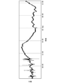
- FIG. 5A and 5B are diagrams illustrating an embodiment of the embodiment of the present invention.
- FIG. 5A is a graph showing a time-series change in tension applied to a resin processed product measured by a tension sensor according to an embodiment of the present invention.
- the vertical axis of FIG. 5A shows tension, and the horizontal axis shows time.
- FIG. 5B is a graph showing a time-series change in the dispersion of acceleration calculated from the acceleration in the roll device 10 measured by the acceleration sensor 6 according to the embodiment of the present invention.
- the vertical axis of FIG. 5B shows the standard deviation of acceleration, and the horizontal axis shows the time.
- the manufacturing process management device 20 has only one axial acceleration in any one of the plurality of accelerations detected by the acceleration sensors 6 provided in each of the plurality of roll devices 10.
- the manufacturing process control device 20 may estimate the tension applied to the resin processed product based on a plurality of axial accelerations.
- the manufacturing process control device 20 estimates the tension applied to the resin processed product based on the information obtained by statistical processing for a plurality of axial accelerations.
- the information regarding the plurality of variances is the information regarding the plurality of accelerations (that is, the acceleration measured by the acceleration sensor 6).
- the function of the manufacturing process control device 20 when estimating the tension applied to the resin processed product based on a plurality of accelerations will be described in detail. The description that overlaps with the functions described in the above-described embodiment will be omitted.
- the communication unit 210 receives the acceleration transmitted from the sensor unit 110 of the roll device 10 and inputs the received acceleration to the control unit 220.
- the number of sensor units 110 for which the communication unit 210 receives acceleration is not particularly limited as long as it is at least one.
- the acceleration received by the sensor unit 110 indicates a velocity in at least two axial directions.
- the acquisition unit 2202 acquires at least two axial accelerations from the communication unit 210.
- at least two axial accelerations are acquired based on at least two spatial axial accelerations in one roll 3.
- the acceleration in at least two axial directions is among the accelerations in the X-axis direction, the Y-axis direction, and the Z-axis direction detected by one acceleration sensor 6 provided in one roll device 10.
- at least two axial accelerations may be acquired based on the accelerations of different rolls 3.
- the acceleration in at least two axial directions is the acceleration detected by the acceleration sensors 6 provided in each of the plurality of roll devices 10.
- the acceleration detected by each acceleration sensor 6 may be acceleration in only one axial direction or may be acceleration in a plurality of axial directions. Further, at least two axial accelerations are a plurality of accelerations detected by a plurality of acceleration sensors provided in a certain roll device 10. In this case, the acceleration detected by each acceleration sensor 6 may be acceleration in only one axial direction or may be acceleration in a plurality of axial directions.
- the calculation unit 2204 performs statistical processing on a plurality of axial accelerations (information on a plurality of dispersions) and calculates information used for estimating the tension applied to the resin processed product. For example, the calculation unit 2204 performs principal component analysis (PCA: Principal Component Analysis) as statistical processing for a plurality of axial accelerations. Specifically, the calculation unit 2204 calculates the standard deviation (variance of acceleration) from the first principal component obtained by performing principal component analysis based on the plurality of axial accelerations acquired by the acquisition unit 2202. The calculation unit 2204 outputs the standard deviation calculated by the principal component analysis to the estimation unit 2206 as information (dispersion information) indicating the variance of the acceleration.
- PCA Principal Component Analysis
- the calculation unit 2204 may calculate the standard deviation after excluding the plurality of axial accelerations outside the predetermined range from the plurality of axial accelerations acquired by the acquisition unit 2202. For example, the calculation unit 2204 extracts a plurality of axial accelerations included in a predetermined range from a plurality of axial accelerations by outlier processing, and outside the predetermined range from the plurality of axial accelerations. Exclude the acceleration of. It is preferable that the predetermined range is set so that a more optimum calculation result can be obtained according to the sensor used, the observation system, and the like. For example, if the predetermined range is too wide, the reproducibility and variation of the data may be impaired, which may affect the calculation result.
- the outlier processing is a processing for excluding the acceleration which is an outlier from the plurality of axial accelerations used for the principal component analysis.
- Outliers are values that deviate significantly from other accelerations that can occur, for example, due to accelerometer failure or disturbance.
- the calculation unit 2204 can exclude values that greatly deviate from other accelerations by outlier processing. That is, the calculation unit 2204 can suppress the influence of the disturbance on the result of the principal component analysis by using a plurality of axial accelerations after the outlier processing. Therefore, the calculation unit 2204 can improve the accuracy of the principal component analysis by the outlier processing.
- the estimation unit 2206 estimates the tension applied to the resin processed product based on the dispersion information calculated by the calculation unit 2204 by the principal component analysis.
- the estimation unit 2206 is based on the correlation between the variation in the dispersion of acceleration calculated by the calculation unit 2204 by the principal component analysis and the variation in the tension applied to the processed resin product, and the variation in the tension applied to the processed resin product. To estimate.
- the estimation unit 2206 can easily estimate the fluctuation of the tension applied to the processed resin product by using the correlation. Further, the estimation unit 2206 can improve the tension estimation accuracy by using the dispersion information calculated by the calculation unit 2204 by the principal component analysis for the tension estimation.
- the correlation between the fluctuation of the dispersion of the acceleration in the roll 3 and the fluctuation of the tension applied to the resin processed product on the tension direction axis is the correlation. .. Therefore, the estimation unit 2206 estimates that when the fluctuation of the dispersion of acceleration tends to increase, the fluctuation of the tension applied to the processed resin product also tends to increase. On the other hand, the estimation unit 2206 estimates that when the fluctuation of the dispersion of acceleration tends to decrease, the fluctuation of the tension applied to the processed resin product also tends to decrease.
- the relationship between the dispersion of acceleration and the fluctuation of tension in this modification is not limited to the correlation relationship, but may be an inverse correlation relationship.
- FIG. 6 is a flowchart showing a processing flow in the manufacturing process control system according to the third modification of the present invention.
- the manufacturing process control system 1 acquires a plurality of axial accelerations in the processed resin product (S202). Specifically, the sensor unit 110 (accelerometer 6) of the roll device 10 detects the acceleration in the resin processed product. The sensor unit 110 transmits the detected acceleration to the manufacturing process control device 20. The acquisition unit 2202 of the manufacturing process control device 20 acquires at least two axial accelerations from the acceleration transmitted from the sensor unit 110 via the communication unit 210.
- the manufacturing process control system 1 performs outlier processing (S204). Specifically, the calculation unit 2204 of the manufacturing process management device 20 performs outlier processing on a plurality of axial accelerations acquired by the acquisition unit 2202, and excludes accelerations outside a predetermined range.
- the manufacturing process control system 1 performs principal component analysis (S206). Specifically, the calculation unit 2204 of the manufacturing process control device 20 performs principal component analysis on a plurality of axial accelerations after outlier processing.
- the manufacturing process control system 1 calculates the variance of the acceleration (S208). Specifically, the calculation unit 2204 of the manufacturing process control device 20 calculates the variance information indicating the variance of the acceleration based on the first principal component (acceleration) obtained by the principal component analysis.
- the manufacturing process control system 1 estimates the tension applied to the processed resin product (S210). Specifically, the estimation unit 2206 of the manufacturing process control device 20 estimates the estimation information indicating the tension applied to the resin processed product based on the correlation between the dispersion information calculated by the calculation unit 2204 and the tension.
- the manufacturing process control system 1 determines the state of the processed resin product (S212). Specifically, the determination unit 2208 of the manufacturing process control device 20 determines the state of the resin processed product based on the estimation information estimated by the estimation unit 2206.
- the manufacturing process control system 1 controls the process conditions (S214). Specifically, the condition control unit 2210 of the manufacturing process management device 20 controls the process conditions based on the determination result determined by the determination unit 2208. After controlling the process conditions, the manufacturing process control system 1 may repeat the process from S202.
- FIGS. 7A to 7D, 8A, and 8B are diagrams illustrating an embodiment of a third modification of the present invention.
- 7A to 7D are diagrams showing the relationship between tension and acceleration depending on whether or not the statistical processing according to the embodiment of the third modification of the present invention is performed.
- the vertical axis of FIGS. 7A to 7D shows the tension measured by the sensor device, and the horizontal axis shows the acceleration measured by the sensor device.
- FIG. 7A shows the tension and the acceleration when both the outlier processing and the principal component analysis are not performed on the acceleration in one axial direction indicated by the acceleration detected by the acceleration sensor 6 provided on the roll 3. It is a figure which shows the relationship of.
- FIG. 7B is a diagram showing the relationship between tension and acceleration when only outlier processing is performed.
- FIG. 7D is a diagram showing the relationship between tension and acceleration when both outlier processing and principal component analysis are performed.
- the accuracy of a certain correlation is further improved as compared with the case where only the principal component analysis shown in FIG. 7C is performed.
- the tension and tension are in the order of not performing both outlier processing and principal component analysis, performing only outlier processing, performing only principal component analysis, and performing both outlier processing and principal component analysis. It can be said that the accuracy of calculating the correlation with acceleration is improved.
- FIG. 8A and 8B are diagrams showing time-series changes according to an embodiment of the third modification of the present invention.
- FIG. 8A is a graph showing a time-series change in tension applied to a resin processed product measured by a tension sensor according to an embodiment of a third modification of the present invention.
- the vertical axis of FIG. 8A shows tension, and the horizontal axis shows time.
- FIG. 8B is a graph showing the time-series changes in the dispersion of acceleration in the roll device 10 measured by the acceleration sensor according to the embodiment of the third modification of the present invention.
- the vertical axis of FIG. 8B shows the standard deviation of acceleration, and the horizontal axis shows the time.
- the manufacturing process control system 1 in the above-described embodiment may be realized by a computer.
- a program for realizing this function may be recorded on a computer-readable recording medium, and the program recorded on the recording medium may be read by a computer system and executed.
- the term "computer system” as used herein includes hardware such as an OS and peripheral devices.
- the "computer-readable recording medium” refers to a portable medium such as a flexible disk, a magneto-optical disk, a ROM, or a CD-ROM, and a storage device such as a hard disk built in a computer system.
- a "computer-readable recording medium” is a communication line for transmitting a program via a network such as the Internet or a communication line such as a telephone line, and dynamically holds the program for a short period of time. It may also include a program that holds a program for a certain period of time, such as a volatile memory inside a computer system that is a server or a client in that case. Further, the above program may be for realizing a part of the above-mentioned functions, and may be further realized for realizing the above-mentioned functions in combination with a program already recorded in the computer system. It may be realized by using a programmable logic device such as FPGA (Field Programmable Gate Array).
- FPGA Field Programmable Gate Array
- Manufacturing process management system Manufactured material 3 Roll 4 Roll shaft 5 Roll bearing 6 Accelerometer 7 Area 10 Roll device 20 Manufacturing process management device 110 Sensor unit 120 Drive unit 210 Communication unit 220 Control unit 230 Storage unit 2202 Acquisition unit 2204 Calculation Part 2206 Estimate part 2208 Judgment part 2210 Condition control part
Abstract
製造工程管理システムは、張力がかかった状態で移動する被製造物と接触し、前記被製造物を支持する支持部材と、前記支持部材の力学的な変動に基づき、前記力学的な変動の分散に関する情報を取得する取得部と、前記被製造物にかかる張力を推定する推定部と、を備える。
Description
本発明は、シート・フィルム・繊維などの成形加工を行う工程などに利用される被製造物に加わる張力測定方法及びその管理装置に係り、特に、合成樹脂繊維の紡糸工程における糸条の張力を、非接触な状態で任意の位置における測定、製造工程管理システム、製造工程管理装置、製造工程管理方法、及びプログラムに関する。
本願は、2020年7月28日に日本に出願された特願2020-127203号、及び2021年3月4日に日本に出願された特願2021-034632号に基づき優先権を主張し、その内容をここに援用する。
本願は、2020年7月28日に日本に出願された特願2020-127203号、及び2021年3月4日に日本に出願された特願2021-034632号に基づき優先権を主張し、その内容をここに援用する。
従来、樹脂からシート、フィルムや繊維が生産されている。その生産工程には、ロールを用いた樹脂の大きな変形を伴う成形加工の工程があり、例えば、樹脂を薄い膜状に成型するフィルム化や、紡糸ノズルから吐出された樹脂を紡ぐ紡糸等の工程が知られている。このような工程において、加えられた変形の履歴は、残留ひずみとして樹脂に記憶され、製品品質や加工安定性に強く影響を与えることが知られているが、物理的制約や経済的制約により、センシング技術導入が見送られることも多い。工程内では、残留ひずみの緩和に伴う収縮応力が発生し、被製造物の張力として検出できる。特に、合成樹脂繊維の紡糸工程において、強すぎる張力は、製品糸の物理的特性に悪影響を与えたり、工程における糸切れ・工程ロールへの巻き付きに繋がる。逆に、低すぎる張力も、製品糸の物理的特性に悪影響を与えたり、工程糸のたるみに繋がり、糸条の走行が不安定になり、糸が傷つき易く糸切れなどの原因となる。この様にロールを用いた成型加工工程では、被製造物の張力は重要な工程管理指標であり、樹脂の張力に基づき、加工される樹脂の品質や工程の管理を行うための技術が各種提案されている。
例えば、下記特許文献1には、プラスチック等の樹脂、布、紙、金属等で形成された帯状又は糸状の部材であるウェブの加工工程において、ウェブにかかる張力をセンサ装置で直接測定し、測定値に基づきウェブにかかる張力を制御する装置に関する技術が開示されている。
また、下記特許文献2には、取得した糸条の張力を高速フーリエ変換することによって、張力振動の変化を周波数領域で監視し、糸条の異常及び加工糸の品質を制御・管理するシステムに関する技術が開示されている。
さらに、下記特許文献3には、糸条の張力検出を非接触で行うために、少量の糸条に対して、赤外線を照射し、透過光から糸条張力を検出する測定方法及び装置に関する技術が開示されている。
下記特許文献4は、ベルトに振動を加え、その際の振動を加速度センサによって取得し、これをフーリエ変換することで固有周波数を求め、得られた振動周波数からベルト張力を算出する方法に関する技術が開示されている。
しかしながら、先行技術文献に示された技術は、特許文献1のような被製造物にかかる張力を直接測定するために、大規模な設備の導入が必要となることや、特許文献2または特許文献3のような少量の繊維に対してしか適用できない場合がある。よって、これらの技術が適用可能な設備や工程は、例えば、大規模な設備が必要あるいは少量の糸束を扱う工程等に限られるといった課題があった。
さらに、特許文献4のように張力を直接測定するのではなく、張力監視の対象の振動からその周波数を求めて張力を算出する場合には、張力監視の対象への振動を付加するとともに検出した加速度の変化から固有振動数を算出し、固有振動数がベルトの振動によるものか否かについての同定を行う必要があるといった事前の作業が必要となる。
上述の課題を鑑み、本発明の目的は、製造工程管理を容易に行うことが可能な製造工程管理システム、製造工程管理装置、製造工程管理方法、及びプログラムを提供することにある。
上述の課題を解決するために、本発明の一態様に係る製造工程管理システムは、張力がかかった状態で移動する被製造物と接触し、前記被製造物を支持する支持部材と、前記支持部材の力学的な変動に基づき、前記力学的な変動の分散に関する情報を取得する取得部と、前記被製造物にかかる張力を推定する推定部と、を備える。
本発明の一態様に係る製造工程管理装置は、張力がかかった状態で移動する被製造物と接触し、前記被製造物を支持する支持部材の力学的な変動に基づき、前記力学的な変動の分散に関する情報を取得する取得部と、前記被製造物にかかる張力を推定する推定部と、を備える。
本発明の一態様に係る製造工程管理方法は、取得部が、張力がかかった状態で移動する被製造物と接触し、前記被製造物を支持する支持部材の力学的な変動に基づき、前記力学的な変動の分散に関する情報を取得することと、推定部が、前記被製造物にかかる張力を推定することと、を含む。
本発明の一態様に係るプログラムは、コンピュータを、張力がかかった状態で移動する被製造物と接触し、前記被製造物を支持する支持部材の力学的な変動に基づき、前記力学的な変動の分散に関する情報を取得する取得部と、前記被製造物にかかる張力を推定する推定部と、として機能させる。
本発明によれば、製造工程管理を容易に行うことができる。
以下、図面を参照しながら本発明の実施形態について詳しく説明する。図面には、必要に応じて相互に直交するX軸、Y軸、及びZ軸(空間軸)が示されている。各軸において、矢印が延びる方向を「正方向」、正方向と逆の方向を「負方向」と称する。
<1.製造工程概要>
図1は、本発明の実施形態に係る被製造物の製造工程の一例を示す図である。図1には、製造工程の一例として、被製造物2が成形加工される成形加工工程が示されている。以下、被製造物2の成形加工工程の管理を一例として、本発明について説明する。
図1は、本発明の実施形態に係る被製造物の製造工程の一例を示す図である。図1には、製造工程の一例として、被製造物2が成形加工される成形加工工程が示されている。以下、被製造物2の成形加工工程の管理を一例として、本発明について説明する。
被製造物2は、例えば、繊維状の合成樹脂である。当該合成樹脂は、熱可塑性を有する熱可塑性樹脂である。本実施形態では、成形加工工程にて合成樹脂が加工され、フィルム、シート、繊維等の樹脂加工品が生産される。以下、本実施形態では、合成樹脂から生産された樹脂加工品が被製造物2であるものとして説明する。
成形加工工程では、図1に示すように、複数のロール3が設けられている。ロール3は、本実施形態に係る支持部材の一例である。ロール3は、張力がかかった状態で移動する被製造物2と接触し、被製造物2を支持する。なお、成形加工工程に設けられるロール3の数と配置は、図1に示す例に限定されない。
ロール3は、ロール軸4を軸に回転する。樹脂加工品は、ロール3と接触するように配置される。樹脂加工品は、ロール3が回転することによって成形(例えば伸長)されながら、Y軸の正方向又は負方向への移動とZ軸の正方向への移動を繰り返す。これにより、樹脂加工品は、上流工程から下流工程へ移動させられる。
図1では、一例として、X軸方向から見た際の樹脂加工品の形状がU字となるように、樹脂加工品とロール3が接触させられている。なお、樹脂加工品とロール3との接触のさせ方は、図1に示す例に限定されない。樹脂加工品とロール3との接触のさせ方は、ロール3の配置に応じて変化し得る。
<2.ロール装置の構成>
図2は、本発明の実施形態に係るロール装置の構成の一例を示す図である。図2に示すように、ロール装置10は、ロール3、ロール軸4、ロール軸受け5、及び加速度センサ6で構成される。ロール3は、ロール軸4を介して、ロール軸受け5と接続されている。
図2は、本発明の実施形態に係るロール装置の構成の一例を示す図である。図2に示すように、ロール装置10は、ロール3、ロール軸4、ロール軸受け5、及び加速度センサ6で構成される。ロール3は、ロール軸4を介して、ロール軸受け5と接続されている。
ロール装置10には、ロール3における測定値を検出するためのセンサ装置が設けられる。センサ装置は、加速度センサ6である。加速度センサ6は、既存の設備への導入が容易であるだけでなく、工程温度が高い等の制約から張力センサの導入が困難であった箇所への導入も可能である。加速度センサ6は、ロール装置10に対して取り付けられる。加速度センサ6は、ロール軸受け5の上部(図2に示す領域7)に取り付けられる。ただし、加速度センサ6は、ロール軸受け5の他の位置に取り付けられてもよいし、その他、ロール3又はロール軸4の振動を検出可能な位置であれば任意の位置であってもよい。また、加速度センサ6は、1つのロール軸受け5に対して、複数取り付けられてもよい。
加速度センサ6は、ロール3の回転動力に応じた加速度を検出する。当該加速度センサ6には、例えば、3軸方向の加速度を検出可能なセンサが用いられる。製造工程管理システムは、検出された加速度(力学的な変動の一例)の分散を算出し、算出した分散に基づき、樹脂加工品にかかる張力を推定する。ただし、製造工程管理システムはこれに限らず、加速度に代えて、速度や位置の分散に基づき、張力が推定されてもよい。また、張力を推定するための加速度、速度又は位置は、張力がかかった場合には、張力のかからない場合の測定値を基準として正負の値を繰り返すもの(力学的な変動)である。なお、本実施形態では、加速度センサ6が検出した3軸方向の各々の加速度の内、樹脂加工品にかかる張力の変動が加速度の変動に最も強く作用する方向の加速度(即ち1つの軸方向の加速度のみ)が、樹脂加工品にかかる張力の推定に用いられる。
なお、力学的な変動の検出には、工程条件が加味されてもよい。工程条件は、成形加工工程において設定される条件であり、例えば、樹脂加工品の物性に関わる温度や生産速度である。工程条件は、樹脂加工品における残留ひずみや収縮応力に大きく影響する。残留ひずみや収縮応力は、樹脂加工品にかかる張力に影響を与える。よって、力学的な変動の検出に工程条件を加味することで、樹脂加工品にかかる張力をより精度高く推定することができる。また、純粋な樹脂に関する物性情報を得るために、工程条件を加味した力学的な変動を得る場合もある。
<3.製造工程管理システムの機能構成>
図3は、本発明の実施形態に係る製造工程管理システムの機能構成の一例を示すブロック図である。図3に示すように、製造工程管理システム1は、ロール装置10及び製造工程管理装置20を有する。
図3は、本発明の実施形態に係る製造工程管理システムの機能構成の一例を示すブロック図である。図3に示すように、製造工程管理システム1は、ロール装置10及び製造工程管理装置20を有する。
<3-1.ロール装置の機能構成>
ロール装置10は、樹脂加工品に対して伸長等の加工を行う装置である。ロール装置10は、図3に示すように、センサ部110及び駆動部120を有する。
ロール装置10は、樹脂加工品に対して伸長等の加工を行う装置である。ロール装置10は、図3に示すように、センサ部110及び駆動部120を有する。
(1)センサ部110
センサ部110は、ロール3における測定値を検出する機能を有する。センサ部110の機能は、加速度センサ6によって実現される。センサ部110は、加速度センサ6によって検出されたロール3の回転動力に応じた加速度を製造工程管理装置20へ送信する。
センサ部110は、ロール3における測定値を検出する機能を有する。センサ部110の機能は、加速度センサ6によって実現される。センサ部110は、加速度センサ6によって検出されたロール3の回転動力に応じた加速度を製造工程管理装置20へ送信する。
(2)駆動部120
駆動部120は、ロール装置10を駆動させる機能を有する。駆動部120の機能は、モータによって実現される。駆動部120の動作は、製造工程管理装置20によって制御される。
駆動部120は、ロール装置10を駆動させる機能を有する。駆動部120の機能は、モータによって実現される。駆動部120の動作は、製造工程管理装置20によって制御される。
<3-2.製造工程管理装置20の機能構成>
製造工程管理装置20は、ロール装置10の動作を制御して樹脂加工品の成形加工工程を管理する装置である。製造工程管理装置20は、例えば、PC(Personal Computer)、スマートフォン、タブレット端末、サーバ端末等によって実現される。製造工程管理装置20は、図3に示すように、通信部210、制御部220、及び記憶部230を有する。
製造工程管理装置20は、ロール装置10の動作を制御して樹脂加工品の成形加工工程を管理する装置である。製造工程管理装置20は、例えば、PC(Personal Computer)、スマートフォン、タブレット端末、サーバ端末等によって実現される。製造工程管理装置20は、図3に示すように、通信部210、制御部220、及び記憶部230を有する。
(1)通信部210
通信部210は、各種情報の送受信を行う機能を有する。例えば、通信部210は、制御部220から入力される制御情報をロール装置10へ送信する。当該制御情報は、例えば、ロール装置10の駆動部120の動作を制御するための情報である。また、通信部210は、ロール装置10のセンサ部110から送信される加速度を受信し、受信した加速度を制御部220へ入力する。なお、通信部210における通信は、無線通信により行われる。
通信部210は、各種情報の送受信を行う機能を有する。例えば、通信部210は、制御部220から入力される制御情報をロール装置10へ送信する。当該制御情報は、例えば、ロール装置10の駆動部120の動作を制御するための情報である。また、通信部210は、ロール装置10のセンサ部110から送信される加速度を受信し、受信した加速度を制御部220へ入力する。なお、通信部210における通信は、無線通信により行われる。
(2)制御部220
制御部220は、製造工程管理装置20の動作全般を制御する機能を有する。制御部220は、例えば、製造工程管理装置20がハードウェアとして備えるCPU(Central Processing Unit)にプログラムを実行させることによって実現される。
制御部220は、製造工程管理装置20の動作全般を制御する機能を有する。制御部220は、例えば、製造工程管理装置20がハードウェアとして備えるCPU(Central Processing Unit)にプログラムを実行させることによって実現される。
制御部220は、図3に示すように、取得部2202、算出部2204、推定部2206、判定部2208、及び条件制御部2210を有する。
(2-1)取得部2202
取得部2202は、加速度を取得する。例えば、取得部2202は、通信部210がロール装置10のセンサ部110から受信した加速度を取得する。取得部2202は、取得した加速度を算出部2204へ入力する。取得部2202が取得する加速度は、力学的な変動の分散に関する情報の一例である。当該情報は、加速度に限定されない。
取得部2202は、加速度を取得する。例えば、取得部2202は、通信部210がロール装置10のセンサ部110から受信した加速度を取得する。取得部2202は、取得した加速度を算出部2204へ入力する。取得部2202が取得する加速度は、力学的な変動の分散に関する情報の一例である。当該情報は、加速度に限定されない。
(2-2)算出部2204
算出部2204は、ロール3における加速度に基づき、加速度の分散を算出する。算出部2204は、取得部2202から入力される加速度に基づき、加速度の分散を算出する。算出部2204は、算出した加速度の分散を示す情報(以下、「分散情報」とも称される)を推定部2206へ入力する。
算出部2204は、ロール3における加速度に基づき、加速度の分散を算出する。算出部2204は、取得部2202から入力される加速度に基づき、加速度の分散を算出する。算出部2204は、算出した加速度の分散を示す情報(以下、「分散情報」とも称される)を推定部2206へ入力する。
ここで、加速度の分散の算出方法の一例について説明する。加速度センサ6は、1秒間に100点、すなわち0.01秒に1回測定を行うものとする。算出部2204は、加速度センサ6が1分間測定を行った測定結果(6000点)に基づき、標準偏差を分散として算出する。なお、加速度センサ6による加速度の測定周期は、かかる例に限定されない。加速度センサ6による加速度の測定周期は、例えば、張力の推定に必要となる精度に応じて適宜変更されてよい。
(2-3)推定部2206
推定部2206は、樹脂加工品にかかる張力を推定する。例えば、推定部2206は、算出部2204から入力される分散情報に基づき、樹脂加工品にかかる張力を推定する。具体的に、推定部2206は、分散情報と樹脂加工品にかかる張力との相関関係に基づき、樹脂加工品にかかる張力を推定する。推定部2206は、推定した張力を示す情報(以下、「推定情報」とも称される)を判定部2208へ入力する。
推定の一例として、推定部2206は、ロール3が樹脂加工品から受ける張力の方向によって定まる張力方向軸における、加速度の分散の変動と、樹脂加工品にかかる張力の変動との相関関係に基づき、樹脂加工品にかかる張力の変動を推定する。推定部2206は、当該相関関係を用いることで、樹脂加工品にかかる張力の変動を容易に推定することができる。
なお、加速度の分散と張力の相関関係は、張力の大きさに応じて、相関の関係(正の相関関係)あるいは逆相関の関係(負の相関関係)のいずれかの関係となり得る。
例えば、ロール3が何も支持していない状態でロール3が回転すると、ロール3には全方向に対して振動が生じ得る。
これに対して、樹脂加工品がロール3に支持された状態でロール3が回転することによって、樹脂加工品が成形されながら上流工程から下流工程へ移動しているとする。この時、樹脂加工品にかかる張力が弱いと、ロール3における振動は、張力に応じて樹脂加工品と平行方向へと引っ張られる。即ち、張力が大きくなると振動(加速度)も大きくなり、張力が小さくなると振動(加速度)も小さくなる。よって、樹脂加工品にかかる張力が弱い場合、加速度の分散と張力は相関の関係にある。一方、樹脂加工品にかかる張力が強いと、ロール3における振動は、張力に応じて樹脂加工品と平行方向で抑制される。即ち、張力が大きくなると振動(加速度)は小さくなり、張力が小さくなると振動(加速度)は大きくなる。よって、樹脂加工品にかかる張力が強い場合、加速度の分散と張力は逆相関の関係にある。
以下、本実施形態では、加速度の分散と張力の変動との間に逆相関の関係がある例について説明する。なお、後述する実施例では、ロール3における加速度の分散の変動と樹脂加工品にかかる張力の変動との張力方向軸における相関関係が、逆相関の関係であることが示されている。よって、推定部2206は、加速度の分散の変動が増加傾向にある場合には樹脂加工品にかかる張力の変動が減少傾向にあると推定する。一方、推定部2206は、加速度の分散の変動が減少傾向にある場合には樹脂加工品にかかる張力の変動が増加傾向にあると推定する。なお、加速度センサ6が検出する3軸方向の加速度の内、加速度の変動が最も大きい軸との相関関係が最も大きくなり得る。なお、本実施形態における加速度の分散と張力の変動との間の関係は逆相関の関係に限定されず、相関の関係であってもよい。
推定部2206は、樹脂加工品の少なくとも一つの工程条件に基づき、樹脂加工品にかかる張力を推定してもよい。工程条件は、例えば、樹脂加工品の工程温度または生産速度等である。これにより、推定部2206は、樹脂加工品における残留ひずみや収縮応力を加味した張力を推定することができる。よって、推定部2206は、樹脂加工品にかかる張力の推定精度を向上することができる。
(2-4)判定部2208
判定部2208は、推定された樹脂加工品にかかる張力に基づき、樹脂加工品の状態を判定する。例えば、判定部2208は、推定部2206から入力される推定情報に基づき、樹脂加工品の状態を判定する。判定部2208は、樹脂加工品の状態の判定結果を条件制御部2210へ入力する。
判定部2208は、推定された樹脂加工品にかかる張力に基づき、樹脂加工品の状態を判定する。例えば、判定部2208は、推定部2206から入力される推定情報に基づき、樹脂加工品の状態を判定する。判定部2208は、樹脂加工品の状態の判定結果を条件制御部2210へ入力する。
例えば、推定情報が示す張力の変動が安定している場合、判定部2208は、樹脂加工品の状態が良好であると判定する。張力の変動が安定している状態の一例として、前回入力された推定情報が示す張力の変動と今回入力された推定情報が示す張力の変動との差分が所定の閾値未満である状態が挙げられる。
一方、推定情報が示す張力の変動が不安定である場合、判定部2208は、樹脂加工品の状態が異常であると判定する。張力の変動が不安定な状態の一例として、前回入力された推定情報が示す張力の変動と今回入力された推定情報が示す張力の変動との差分が所定の閾値以上である状態が挙げられる。当該差分が所定の閾値以上である状態の一例として、張力の変動が急増あるいは急減している状態が挙げられる。張力の変動が不安定となる要因として、例えば、樹脂加工品がロール3に巻き付くことや、樹脂加工品が切断すること等が挙げられる。
判定部2208は、異常な状態となっている樹脂加工品の位置を判定することができる。例えば、判定部2208は、樹脂加工品の状態の判定に用いた推定情報の大元となる加速度を検出した加速度センサ6を特定する。これにより判定部2208は、特定した加速度センサ6が設けられたロール装置10にて樹脂加工品の状態に異常が生じていると把握することができる。
(2-5)条件制御部2210
条件制御部2210は、樹脂加工品の状態に応じて、樹脂加工品の工程条件を制御する。例えば、条件制御部2210は、判定部2208から入力される判定結果に応じて、樹脂加工品の工程条件を変更する。条件制御部2210は、通信部210を介して、変更後の工程条件を示す制御情報をロール装置10の駆動部120へ送信する。
条件制御部2210は、樹脂加工品の状態に応じて、樹脂加工品の工程条件を制御する。例えば、条件制御部2210は、判定部2208から入力される判定結果に応じて、樹脂加工品の工程条件を変更する。条件制御部2210は、通信部210を介して、変更後の工程条件を示す制御情報をロール装置10の駆動部120へ送信する。
樹脂加工品の状態が異常であると判定された場合、条件制御部2210は、樹脂加工品の状態に応じて樹脂加工品の工程条件を変更する。例えば、条件制御部2210は、樹脂加工品の生産速度を遅くする。樹脂加工品にかかる張力の大きさは、生産速度が速いほど大きくなり得る。そのため、条件制御部2210は、生産速度を遅くすることで、樹脂加工品にかかる張力の大きさを小さくすることができる。
一方、樹脂加工品の状態が良好であると判定された場合、条件制御部2210は、樹脂加工品の生産速度を加速する。条件制御部2210は、樹脂加工品の状態が異常な状態にならない程度に生産速度を加速する。これにより、条件制御部2210は、樹脂加工品の生産性を向上することができる。
(3)記憶部230
記憶部230は、各種情報を記憶する機能を有する。記憶部230は、記憶媒体、例えば、HDD(Hard Disk Drive)、フラッシュメモリ、EEPROM(Electrically Erasable Programmable Read Only Memory)、RAM(Random Access read/write Memory)、ROM(Read Only Memory)、またはこれらの記憶媒体の任意の組み合わせによって構成される。記憶部230は、例えば、不揮発性メモリを用いることができる。
記憶部230は、各種情報を記憶する機能を有する。記憶部230は、記憶媒体、例えば、HDD(Hard Disk Drive)、フラッシュメモリ、EEPROM(Electrically Erasable Programmable Read Only Memory)、RAM(Random Access read/write Memory)、ROM(Read Only Memory)、またはこれらの記憶媒体の任意の組み合わせによって構成される。記憶部230は、例えば、不揮発性メモリを用いることができる。
<4.処理の流れ>
図4は、本実施形態に係る製造工程管理システム1における処理の流れを示すフローチャートである。
図4は、本実施形態に係る製造工程管理システム1における処理の流れを示すフローチャートである。
図4に示すように、まず、製造工程管理システム1は、樹脂加工品における加速度を取得する(S102)。具体的に、ロール装置10のセンサ部110(加速度センサ6)が樹脂加工品における加速度を検出する。センサ部110は、検出した加速度を製造工程管理装置20へ送信する。製造工程管理装置20の取得部2202は、通信部210を介して、センサ部110から送信される加速度を取得する。
次いで、製造工程管理システム1は、加速度の分散を算出する(S104)。具体的に、製造工程管理装置20の算出部2204は、取得部2202が取得する加速度に基づき、加速度の分散を示す分散情報を算出する。
次いで、製造工程管理システム1は、樹脂加工品にかかる張力を推定する(S106)。具体的に、製造工程管理装置20の推定部2206は、算出部2204が算出した分散情報と張力との相関関係に基づき、樹脂加工品にかかる張力を示す推定情報を推定する。
次いで、製造工程管理システム1は、樹脂加工品の状態を判定する(S108)。具体的に、製造工程管理装置20の判定部2208は、推定部2206が推定した推定情報に基づき、樹脂加工品の状態を判定する。
最後に、製造工程管理システム1は、工程条件を制御する(S110)。具体的に、製造工程管理装置20の条件制御部2210は、判定部2208が判定した判定結果に基づき、工程条件を制御する。
なお、工程条件の制御後、製造工程管理システム1は、S102から処理を繰り返してもよい。
なお、工程条件の制御後、製造工程管理システム1は、S102から処理を繰り返してもよい。
以上説明したように、本実施形態に係る製造工程管理システム1は、張力がかかった状態で移動する樹脂加工品と接触し、当該樹脂加工品を支持するロール3を有する。
製造工程管理システム1は、ロール3における加速度に基づき、加速度の分散を算出する。
製造工程管理システム1は、樹脂加工品にかかる張力を推定する。
製造工程管理システム1は、ロール3における加速度に基づき、加速度の分散を算出する。
製造工程管理システム1は、樹脂加工品にかかる張力を推定する。
かかる構成により、製造工程管理システム1は、樹脂加工品と接触するロール3における加速度に基づき、樹脂加工品にかかる張力を推定する。これにより、製造工程管理システム1は、張力センサを用いることなく、樹脂加工品にかかる張力を容易に推定することができる。即ち、張力センサの導入が困難な設備であっても、ロール3における加速度を検出可能なセンサ装置(加速度センサ6)を用いることで、ロール3にかかる張力を容易に推定することができる。
よって、本実施形態に係る製造工程管理システム1は、製造工程管理を容易に行うことができる。
<5.実施例>
本発明の実施形態に係る実施例では、張力センサを用いて測定した樹脂加工品にかかる張力と、加速度センサ6を用いて測定したロール装置10における加速度から算出した加速度の分散(標準偏差)とを比較する。これにより、樹脂加工品にかかる張力と、ロール装置10における加速度の分散とに相関関係があることを確認する。
本発明の実施形態に係る実施例では、張力センサを用いて測定した樹脂加工品にかかる張力と、加速度センサ6を用いて測定したロール装置10における加速度から算出した加速度の分散(標準偏差)とを比較する。これにより、樹脂加工品にかかる張力と、ロール装置10における加速度の分散とに相関関係があることを確認する。
本実施例では、張力センサは、ロール3から伝播する張力を測定可能な位置であれば任意の位置に設けられてよい。また、本実施例では、ロール3に対して樹脂加工品がU字にかかっている工程(図1参照)におけるロール3を、加速度センサ6の設置対象ロールとした。加速度センサ6の具体的な設置位置は、図2に示したロール軸受け5の上部(領域7)である。なお、加速度センサ6が測定する加速度の方向は、樹脂加工品にかかる張力の変動が加速度の変動に最も強く作用する方向とする。
本実施例では、加速度センサ6は、1秒間に100点、すなわち0.01秒に1回測定を行うものとする。加速度の標準偏差は、加速度センサ6が1分間測定を行った測定結果(6000点)に基づき算出される。
図5A及び図5Bは、本発明の実施形態の実施例を説明する図である。図5Aは、本発明の実施形態の実施例に係る張力センサによって測定される樹脂加工品にかかる張力の時系列変化を示すグラフである。図5Aの縦軸は張力を示し、横軸は時刻を示している。図5Bは、本発明の実施形態の実施例に係る加速度センサ6によって測定されるロール装置10における加速度から算出される加速度の分散の時系列変化を示すグラフである。図5Bの縦軸は加速度の標準偏差を示し、横軸は時刻を示している。
図5Aに示される張力の時系列変化と、図5Bに示される加速度の標準偏差とを比較すると、張力の変動に逆相関(負の相関)するような形で加速度の標準偏差が変動していることが分かる。よって、樹脂加工品にかかる張力と、ロール装置10における加速度の標準偏差(分散)との間に相関関係(負の相関関係)があるといえる。
<6.変形例>
最後に、本発明の実施形態の変形例について説明する。なお、以下に説明する各変形例は、単独で本発明の実施形態に適用されてもよいし、組み合わせで本発明の実施形態に適用されてもよい。また、各変形例は、本発明の実施形態で説明した構成に代えて適用されてもよいし、本発明の各実施形態で説明した構成に対して追加的に適用されてもよい。
最後に、本発明の実施形態の変形例について説明する。なお、以下に説明する各変形例は、単独で本発明の実施形態に適用されてもよいし、組み合わせで本発明の実施形態に適用されてもよい。また、各変形例は、本発明の実施形態で説明した構成に代えて適用されてもよいし、本発明の各実施形態で説明した構成に対して追加的に適用されてもよい。
<6-1.第1の変形例>
上述の実施形態では、センサ装置として加速度センサ6が用いられる例について説明したが、かかる例に限定されない。センサ装置には、振動センサが用いられてもよい。この場合、製造工程管理システム1は、振動センサが計測する値に基づき、樹脂加工品にかかる張力を推定する。
上述の実施形態では、センサ装置として加速度センサ6が用いられる例について説明したが、かかる例に限定されない。センサ装置には、振動センサが用いられてもよい。この場合、製造工程管理システム1は、振動センサが計測する値に基づき、樹脂加工品にかかる張力を推定する。
<6-2.第2の変形例>
上述の実施形態では、製造工程管理システム1が加速度センサ6によって計測される加速度に基づき、樹脂加工品にかかる張力を推定する例について説明したが、かかる例に限定されない。製造工程管理システム1は、加速度センサ6によって計測される加速度をフーリエ変換したデータに基づき、樹脂加工品にかかる張力を推定してもよい。
上述の実施形態では、製造工程管理システム1が加速度センサ6によって計測される加速度に基づき、樹脂加工品にかかる張力を推定する例について説明したが、かかる例に限定されない。製造工程管理システム1は、加速度センサ6によって計測される加速度をフーリエ変換したデータに基づき、樹脂加工品にかかる張力を推定してもよい。
<6-3.第3の変形例>
上述の実施形態では、製造工程管理装置20が、複数のロール装置10の各々に設けられた加速度センサ6によって検出される複数の加速度の内、いずれか1つの加速度における1つの軸方向の加速度のみに基づき、樹脂加工品にかかる張力を推定する例について説明したが、かかる例に限定されない。例えば、製造工程管理装置20は、複数の軸方向の加速度に基づき、樹脂加工品にかかる張力を推定してもよい。具体的に、製造工程管理装置20は、複数の軸方向の加速度に対する統計的処理によって得られる情報に基づき、樹脂加工品にかかる張力を推定する。なお、複数の分散に関する情報は、複数の加速度に関する情報(即ち、加速度センサ6によって計測される加速度)であるものとする。
以下、複数の加速度に基づき樹脂加工品にかかる張力を推定する場合の製造工程管理装置20の機能について詳細に説明する。なお、上述の実施形態にて説明した機能と重複する説明については省略する。
(1)機能構成
通信部210は、ロール装置10のセンサ部110から送信される加速度を受信し、受信した加速度を制御部220へ入力する。なお、通信部210が加速度を受信するセンサ部110の数は、少なくとも1つ以上であれば特に限定されない。なお、通信部210が加速度を受信するセンサ部110の数が1つである場合、当該センサ部110か受信する加速度は少なくとも2軸方向の速度を示すものとする。
通信部210は、ロール装置10のセンサ部110から送信される加速度を受信し、受信した加速度を制御部220へ入力する。なお、通信部210が加速度を受信するセンサ部110の数は、少なくとも1つ以上であれば特に限定されない。なお、通信部210が加速度を受信するセンサ部110の数が1つである場合、当該センサ部110か受信する加速度は少なくとも2軸方向の速度を示すものとする。
取得部2202は、通信部210から少なくとも2つの軸方向の加速度を取得する。 例えば、少なくとも2つの軸方向の加速度は、1つのロール3の少なくとも2つの空間軸方向の加速度に基づき取得される。具体的に、少なくとも2つの軸方向の加速度は、ある1つのロール装置10に設けられた1つの加速度センサ6によって検出されたX軸方向、Y軸方向、及びZ軸方向の加速度の内、の少なくとも2つの軸方向の加速度である。 また、少なくとも2つの軸方向の加速度は、異なるロール3ごとの加速度に基づき取得されてもよい。具体的に、少なくとも2つの軸方向の加速度は、複数のロール装置10の各々に設けられた加速度センサ6によって検出される加速度である。この場合、各加速度センサ6が検出する加速度は、1軸方向のみの加速度であってもよいし、複数の軸方向の加速度であってもよい。
また、少なくとも2つの軸方向の加速度は、ある1つのロール装置10に設けられた複数の加速度センサによって検出される複数の加速度である。この場合、各加速度センサ6が検出する加速度は、1軸方向のみの加速度であってもよいし、複数の軸方向の加速度であってもよい。
また、少なくとも2つの軸方向の加速度は、ある1つのロール装置10に設けられた複数の加速度センサによって検出される複数の加速度である。この場合、各加速度センサ6が検出する加速度は、1軸方向のみの加速度であってもよいし、複数の軸方向の加速度であってもよい。
算出部2204は、複数の軸方向の加速度(複数の分散に関する情報)に対して統計的処理を行い、樹脂加工品にかかる張力の推定に用いられる情報を算出する。例えば、算出部2204は、複数の軸方向の加速度に対して、主成分分析(PCA:Principal Component Analysis)を統計的処理として行う。具体的に、算出部2204は、取得部2202によって取得された複数の軸方向の加速度に基づき、主成分分析を行って得られる第1主成分より、標準偏差(加速度の分散)を算出する。算出部2204は、主成分分析によって算出した標準偏差を、加速度の分散を示す情報(分散情報)として推定部2206へ出力する。
なお、算出部2204は、取得部2202によって取得された複数の軸方向の加速度から、所定の範囲外の複数の軸方向の加速度を除外してから標準偏差を算出してもよい。例えば、算出部2204は、外れ値処理によって、複数の軸方向の加速度の中から所定の範囲に含まれる複数の軸方向の加速度を抽出し、複数の軸方向の加速度の中から所定の範囲外の加速度を除外する。所定の範囲は、用いるセンサや観測系等に応じて、より最適な算出結果を得られるように設定されることが好ましい。例えば、所定の範囲を広くしすぎると、データの再現性やばらつきを損ない、算出結果に影響し得る場合がある。一方、所定の範囲を狭くしすぎても、外れ値を除外しきれず、算出結果に影響し得る場合がある。本実施形態にて用いるセンサと観測系の場合、最適な所定の範囲は、例えば、2σ(σ:標準偏差)である。このように、外れ値処理は、主成分分析に用いる複数の軸方向の加速度の中から、外れ値である加速度を除外するための処理である。外れ値は、例えば、加速度センサの故障や外乱によって生じ得る、他の加速度から大きく外れた値である。算出部2204は、外れ値処理によって、他の加速度から大きく外れた値を除外することができる。即ち、算出部2204は、外れ値処理後の複数の軸方向の加速度を用いることで、主成分分析の結果に対する外乱の影響を抑制することができる。よって、算出部2204は、外れ値処理によって主成分分析の精度を向上することができる。
推定部2206は、算出部2204が主成分分析によって算出した分散情報に基づき、樹脂加工品にかかる張力を推定する。推定の一例として、推定部2206は、算出部2204が主成分分析によって算出した加速度の分散の変動と、樹脂加工品にかかる張力の変動との相関関係に基づき、樹脂加工品にかかる張力の変動を推定する。推定部2206は、当該相関関係を用いることで、樹脂加工品にかかる張力の変動を容易に推定することができる。また、推定部2206は、算出部2204が主成分分析によって算出した分散情報を張力の推定に用いることで、張力の推定精度を向上することができる。
以下、本変形例では、加速度の分散と張力の変動との間に相関の関係がある例について説明する。なお、後述する本変形例の実施例では、ロール3における加速度の分散の変動と樹脂加工品にかかる張力の変動との張力方向軸における相関関係が、相関の関係であることが示されている。よって、推定部2206は、加速度の分散の変動が増加傾向にある場合には樹脂加工品にかかる張力の変動も増加傾向にあると推定する。一方、推定部2206は、加速度の分散の変動が減少傾向にある場合には樹脂加工品にかかる張力の変動も減少傾向にあると推定する。なお、本変形例における加速度の分散と張力の変動との間の関係は相関の関係に限定されず、逆相関の関係であってもよい。
(2)処理の流れ
ここで、図6を参照して、本変形例に係る製造工程管理システム1における処理の流れについて説明する。図6は、本発明の第3の変形例に係る製造工程管理システムにおける処理の流れを示すフローチャートである。
ここで、図6を参照して、本変形例に係る製造工程管理システム1における処理の流れについて説明する。図6は、本発明の第3の変形例に係る製造工程管理システムにおける処理の流れを示すフローチャートである。
図6に示すように、まず、製造工程管理システム1は、樹脂加工品における複数の軸方向の加速度を取得する(S202)。具体的に、ロール装置10のセンサ部110(加速度センサ6)が樹脂加工品における加速度を検出する。センサ部110は、検出した加速度を製造工程管理装置20へ送信する。製造工程管理装置20の取得部2202は、通信部210を介して、センサ部110から送信される加速度から、少なくとも2つの軸方向の加速度を取得する。
次いで、製造工程管理システム1は、外れ値処理を行う(S204)。具体的に、製造工程管理装置20の算出部2204は、取得部2202が取得する複数の軸方向の加速度に対して外れ値処理を行い、所定の範囲外の加速度を除外する。
次いで、製造工程管理システム1は、主成分分析を行う(S206)。具体的に、製造工程管理装置20の算出部2204は、外れ値処理後の複数の軸方向の加速度に対して主成分分析を行う。
次いで、製造工程管理システム1は、加速度の分散を算出する(S208)。具体的に、製造工程管理装置20の算出部2204は、主成分分析によって得られた第1主成分(加速度)に基づき、加速度の分散を示す分散情報を算出する。
次いで、製造工程管理システム1は、樹脂加工品にかかる張力を推定する(S210)。具体的に、製造工程管理装置20の推定部2206は、算出部2204が算出した分散情報と張力との相関関係に基づき、樹脂加工品にかかる張力を示す推定情報を推定する。
次いで、製造工程管理システム1は、樹脂加工品の状態を判定する(S212)。具体的に、製造工程管理装置20の判定部2208は、推定部2206が推定した推定情報に基づき、樹脂加工品の状態を判定する。
最後に、製造工程管理システム1は、工程条件を制御する(S214)。具体的に、製造工程管理装置20の条件制御部2210は、判定部2208が判定した判定結果に基づき、工程条件を制御する。
なお、工程条件の制御後、製造工程管理システム1は、S202から処理を繰り返してもよい。
なお、工程条件の制御後、製造工程管理システム1は、S202から処理を繰り返してもよい。
(3)実施例
本発明の第3の変形例に係る実施例では、張力センサを用いて測定した樹脂加工品にかかる張力と、複数のロール装置10の各々に設けられた加速度センサ6の内、13個の加速度センサ6の3つの軸の加速度(即ち、合計39個の加速度)から算出した加速度の分散(標準偏差)とを比較する。これにより、樹脂加工品にかかる張力と、ロール装置10における複数の加速度の分散とに相関関係があることを確認する。
本発明の第3の変形例に係る実施例では、張力センサを用いて測定した樹脂加工品にかかる張力と、複数のロール装置10の各々に設けられた加速度センサ6の内、13個の加速度センサ6の3つの軸の加速度(即ち、合計39個の加速度)から算出した加速度の分散(標準偏差)とを比較する。これにより、樹脂加工品にかかる張力と、ロール装置10における複数の加速度の分散とに相関関係があることを確認する。
まず、図7Aから図7D、図8A、及び図8Bは、本発明の第3の変形例の実施例を説明する図である。図7Aから図7Dは、本発明の第3の変形例の実施例に係る統計的処理の実施の有無に応じた張力と加速度との関係を示す図である。図7Aから図7Dの縦軸はセンサ装置によって実測された張力を示し、横軸はセンサ装置によって実測された加速度を示す。
図7Aは、あるロール3に設けられた加速度センサ6が検出した加速度が示す1つの軸方向の加速度に対して、外れ値処理と主成分分析の両方を行っていない場合における、張力と加速度との関係を示す図である。図7Aに示す散布図における決定係数は、R2=0.001976であった。当該決定係数より、張力と加速度との間にはほぼ相関関係がないといえる。これは、外れ値が影響しているためである。
図7Bは、外れ値処理のみを行った場合における、張力と加速度との関係を示す図である。図7Bに示す散布図における決定係数は、R2=0.191であった。当該決定係数より、張力と加速度との間に一定の相関関係があるといえる。これは、外れ値処理によって外れ値の影響が抑制されたためである。
図7Cは、主成分分析のみを行った場合における、張力と加速度との関係を示す図である。図7Cに示す散布図における決定係数は、R2=0.4574であった。当該決定係数より、図7Bに示した外れ値処理のみを行う場合と比較し、一定の相関関係の精度が大幅に向上したといえる。
図7Dは、外れ値処理と主成分分析の両方を行った場合における、張力と加速度との関係を示す図である。図7Dに示す散布図における決定係数は、R2=0.4598であった。当該決定係数より、図7Cに示した主成分分析のみを行う場合と比較し、一定の相関関係の精度がさらに向上したといえる。
以上より、外れ値処理と主成分分析の両方を行わない場合、外れ値処理のみを行う場合、主成分分析のみを行う場合、外れ値処理と主成分分析の両方を行う場合の順に、張力と加速度との間の相関関係の算出の精度が向上するといえる。
図8A及び図8Bは、本発明の第3の変形例の実施例に係る時系列変化を示す図である。図8Aは、本発明の第3の変形例の実施例に係る張力センサによって測定される樹脂加工品にかかる張力の時系列変化を示すグラフである。図8Aの縦軸は張力を示し、横軸は時刻を示している。図8Bは、本発明の第3の変形例の実施例に係る加速度センサによって測定されるロール装置10における加速度の分散の時系列変化を示すグラフである。図8Bの縦軸は加速度の標準偏差を示し、横軸は時刻を示している。
図8Aに示される張力の時系列変化と、図8Bに示される加速度の標準偏差とを比較すると、張力の変動に相関(正の相関)するような形で加速度の標準偏差が変動していることが分かる。よって、樹脂加工品にかかる張力と、ロール装置10における加速度の標準偏差(分散)との間に相関関係(正の相関関係)があるといえる。
以上、本発明について説明した。なお、上述した実施形態における製造工程管理システム1をコンピュータで実現するようにしてもよい。その場合、この機能を実現するためのプログラムをコンピュータ読み取り可能な記録媒体に記録して、この記録媒体に記録されたプログラムをコンピュータシステムに読み込ませ、実行することによって実現してもよい。なお、ここでいう「コンピュータシステム」とは、OSや周辺機器等のハードウェアを含むものとする。また、「コンピュータ読み取り可能な記録媒体」とは、フレキシブルディスク、光磁気ディスク、ROM、CD-ROM等の可搬媒体、コンピュータシステムに内蔵されるハードディスク等の記憶装置のことをいう。さらに「コンピュータ読み取り可能な記録媒体」とは、インターネット等のネットワークや電話回線等の通信回線を介してプログラムを送信する場合の通信線のように、短時間の間、動的にプログラムを保持するもの、その場合のサーバやクライアントとなるコンピュータシステム内部の揮発性メモリのように、一定時間プログラムを保持しているものも含んでもよい。また上記プログラムは、前述した機能の一部を実現するためのものであってもよく、さらに前述した機能をコンピュータシステムにすでに記録されているプログラムとの組み合わせで実現できるものであってもよく、FPGA(Field Programmable Gate Array)等のプログラマブルロジックデバイスを用いて実現されるものであってもよい。
以上、図面を参照してこの発明の実施形態について詳しく説明してきたが、具体的な構成は上述のものに限られることはなく、この発明の要旨を逸脱しない範囲内において様々な設計変更等をすることが可能である。
1 製造工程管理システム
2 被製造物
3 ロール
4 ロール軸
5 ロール軸受け
6 加速度センサ
7 領域
10 ロール装置
20 製造工程管理装置
110 センサ部
120 駆動部
210 通信部
220 制御部
230 記憶部
2202 取得部
2204 算出部
2206 推定部
2208 判定部
2210 条件制御部
2 被製造物
3 ロール
4 ロール軸
5 ロール軸受け
6 加速度センサ
7 領域
10 ロール装置
20 製造工程管理装置
110 センサ部
120 駆動部
210 通信部
220 制御部
230 記憶部
2202 取得部
2204 算出部
2206 推定部
2208 判定部
2210 条件制御部
Claims (20)
- 張力がかかった状態で移動する被製造物と接触し、前記被製造物を支持する支持部材と、
前記支持部材の力学的な変動に基づき、前記力学的な変動の分散に関する情報を取得する取得部と、
前記被製造物にかかる張力を推定する推定部と、
を備える、製造工程管理システム。 - 前記支持部材の力学的な変動は、支持部材の加速度である、
請求項1に記載の製造工程管理システム。 - 前記取得部にて取得された前記分散に関する情報より、標準偏差を算出する算出部、
をさらに備える、
請求項1又は請求項2に記載の製造工程管理システム。 - 前記算出部は、前記取得部によって取得された複数の前記分散に関する情報に基づき、主成分分析を行って得られる第1主成分より、前記標準偏差を算出する、
請求項3に記載の製造工程管理システム。 - 前記分散に関する情報は、加速度に関する情報であり、
前記算出部は、前記取得部によって取得された前記加速度に関する情報から、所定の範囲外の値を除外し、前記標準偏差を算出する、
請求項3又は請求項4に記載の製造工程管理システム。 - 複数の前記分散に関する情報は、異なる前記支持部材ごとの前記力学的な変動に基づき取得される、
請求項4又は請求項5に記載の製造工程管理システム。 - 複数の前記分散に関する情報は、前記支持部材の少なくとも2つの空間軸における前記力学的な変動に基づき取得される、
請求項4から請求項6のいずれか1項に記載の製造工程管理システム。 - 前記推定部は、前記被製造物の少なくとも一つの工程条件に基づき、前記被製造物にかかる張力を推定する、
請求項1から請求項7のいずれか1項に記載の製造工程管理システム。 - 前記工程条件は、前記被製造物の工程温度または生産速度である、
請求項8に記載の製造工程管理システム。 - 前記推定部は、前記支持部材が前記被製造物から受ける張力の方向によって定まる張力方向軸における、加速度の分散の変動と、前記被製造物にかかる張力の変動との相関関係に基づき、前記被製造物にかかる張力の変動を推定する、
請求項1から請求項9のいずれか1項に記載の製造工程管理システム。 - 前記支持部材における前記加速度の分散の変動と前記被製造物にかかる張力の変動との前記張力方向軸における前記相関関係は、逆相関の関係にあり、
前記推定部は、前記加速度の分散の変動が増加傾向にある場合には、前記被製造物にかかる張力の変動が減少傾向にあると推定し、前記加速度の分散の変動が減少傾向にある場合には、前記被製造物にかかる張力の変動が増加傾向にあると推定する、
請求項10に記載の製造工程管理システム。 - 推定された前記被製造物にかかる張力に基づき、前記被製造物の状態を判定する判定部と、
判定結果に応じて、前記被製造物の工程条件を制御する条件制御部と、
をさらに備える、
請求項1から請求項11のいずれか1項に記載の製造工程管理システム。 - 前記被製造物の状態が異常であると判定された場合、
前記条件制御部は、前記被製造物の状態に応じて前記被製造物の工程条件を変更する、
請求項12に記載の製造工程管理システム。 - 前記被製造物の状態が異常であると判定された場合、
前記条件制御部は、前記被製造物の生産速度を遅くする、
請求項13に記載の製造工程管理システム。 - 前記被製造物の状態が良好であると判定された場合、
前記条件制御部は、前記被製造物の生産速度を加速する、
請求項12から請求項14のいずれか1項に記載の製造工程管理システム。 - 前記被製造物は、合成樹脂である、
請求項1から請求項15のいずれか1項に記載の製造工程管理システム。 - 前記被製造物は、繊維状である、
請求項1から請求項16のいずれか1項に記載の製造工程管理システム。 - 張力がかかった状態で移動する被製造物と接触し、前記被製造物を支持する支持部材の力学的な変動に基づき、前記力学的な変動の分散に関する情報を取得する取得部と、
前記被製造物にかかる張力を推定する推定部と、
を備える、製造工程管理装置。 - 取得部が、張力がかかった状態で移動する被製造物と接触し、前記被製造物を支持する支持部材の力学的な変動に基づき、前記力学的な変動の分散に関する情報を取得することと、
推定部が、前記被製造物にかかる張力を推定することと、
を含む、製造工程管理方法。 - コンピュータを、
張力がかかった状態で移動する被製造物と接触し、前記被製造物を支持する支持部材の力学的な変動に基づき、前記力学的な変動の分散に関する情報を取得する取得部と、
前記被製造物にかかる張力を推定する推定部と、
として機能させる、プログラム。
Priority Applications (3)
| Application Number | Priority Date | Filing Date | Title |
|---|---|---|---|
| JP2022540042A JP7292520B2 (ja) | 2020-07-28 | 2021-06-01 | 製造工程管理システム、製造工程管理装置、製造工程管理方法、及びプログラム |
| US18/006,851 US20230273606A1 (en) | 2020-07-28 | 2021-06-01 | Manufacturing step management system, manufacturing step management device, manufacturing step management method, and program |
| CN202180049902.2A CN115916676A (zh) | 2020-07-28 | 2021-06-01 | 制造工序管理系统、制造工序管理装置、制造工序管理方法以及程序 |
Applications Claiming Priority (4)
| Application Number | Priority Date | Filing Date | Title |
|---|---|---|---|
| JP2020127203 | 2020-07-28 | ||
| JP2020-127203 | 2020-07-28 | ||
| JP2021-034632 | 2021-03-04 | ||
| JP2021034632 | 2021-03-04 |
Publications (1)
| Publication Number | Publication Date |
|---|---|
| WO2022024543A1 true WO2022024543A1 (ja) | 2022-02-03 |
Family
ID=80035382
Family Applications (1)
| Application Number | Title | Priority Date | Filing Date |
|---|---|---|---|
| PCT/JP2021/020842 WO2022024543A1 (ja) | 2020-07-28 | 2021-06-01 | 製造工程管理システム、製造工程管理装置、製造工程管理方法、及びプログラム |
Country Status (4)
| Country | Link |
|---|---|
| US (1) | US20230273606A1 (ja) |
| JP (1) | JP7292520B2 (ja) |
| CN (1) | CN115916676A (ja) |
| WO (1) | WO2022024543A1 (ja) |
Citations (3)
| Publication number | Priority date | Publication date | Assignee | Title |
|---|---|---|---|---|
| JPH02117558A (ja) * | 1988-10-21 | 1990-05-02 | Mitsubishi Electric Corp | 張力制御用回転機の駆動制御装置 |
| JPH0475868U (ja) * | 1990-11-13 | 1992-07-02 | ||
| JP2018009989A (ja) * | 2012-12-12 | 2018-01-18 | バンドー化学株式会社 | 固有周波数測定装置、ベルト張力算出プログラム及び方法、並びにベルト固有周波数算出プログラム及び方法 |
-
2021
- 2021-06-01 US US18/006,851 patent/US20230273606A1/en active Pending
- 2021-06-01 JP JP2022540042A patent/JP7292520B2/ja active Active
- 2021-06-01 WO PCT/JP2021/020842 patent/WO2022024543A1/ja active Application Filing
- 2021-06-01 CN CN202180049902.2A patent/CN115916676A/zh active Pending
Patent Citations (3)
| Publication number | Priority date | Publication date | Assignee | Title |
|---|---|---|---|---|
| JPH02117558A (ja) * | 1988-10-21 | 1990-05-02 | Mitsubishi Electric Corp | 張力制御用回転機の駆動制御装置 |
| JPH0475868U (ja) * | 1990-11-13 | 1992-07-02 | ||
| JP2018009989A (ja) * | 2012-12-12 | 2018-01-18 | バンドー化学株式会社 | 固有周波数測定装置、ベルト張力算出プログラム及び方法、並びにベルト固有周波数算出プログラム及び方法 |
Also Published As
| Publication number | Publication date |
|---|---|
| US20230273606A1 (en) | 2023-08-31 |
| CN115916676A (zh) | 2023-04-04 |
| JP7292520B2 (ja) | 2023-06-16 |
| JPWO2022024543A1 (ja) | 2022-02-03 |
Similar Documents
| Publication | Publication Date | Title |
|---|---|---|
| JP6140331B1 (ja) | 主軸または主軸を駆動するモータの故障予知を学習する機械学習装置および機械学習方法、並びに、機械学習装置を備えた故障予知装置および故障予知システム | |
| Soylemezoglu et al. | Mahalanobis Taguchi system (MTS) as a prognostics tool for rolling element bearing failures | |
| CN111836769B (zh) | 卷绕条件生成装置及计算方法、卷绕装置及方法与卷绕缺陷等级预测值生成装置及方法 | |
| JP5158018B2 (ja) | 生産システムの設備診断装置および設備診断方法、並びに設備診断プログラムおよびこれを記録したコンピュータ読み取り可能な記録媒体 | |
| JP5631481B2 (ja) | 圧延制御装置、圧延制御方法および圧延制御プログラム | |
| WO2010116412A1 (ja) | ワイヤ放電加工機のワイヤ走行系保全システム | |
| US8988239B2 (en) | Failure alarm system and method of failure alarming thereof | |
| WO2022024543A1 (ja) | 製造工程管理システム、製造工程管理装置、製造工程管理方法、及びプログラム | |
| JP7398443B2 (ja) | 包装機における故障予測の方法 | |
| CN105050926A (zh) | 对介质堵塞的音频检测 | |
| Shui et al. | Twofold variation propagation modeling and analysis for roll-to-roll manufacturing systems | |
| JP7200642B2 (ja) | ロール状態の監視装置及びカレンダー装置並びにロール状態の監視方法 | |
| CN103097863B (zh) | 一种用于识别转速传感器的转速信号的偏差的方法及装置 | |
| KR102384742B1 (ko) | 센서 데이터를 이용한 이상 감지 장치 및 방법 | |
| JP2023081437A (ja) | 工程管理装置、工程管理方法、及びプログラム | |
| EP0149300B1 (en) | Method for indicating an insufficient level of yarn finish | |
| TWI703421B (zh) | 位置誤差測定方法、用於開設孔洞的裝置及其應用 | |
| JP2015009261A (ja) | 冷間圧延機のチャタリング検出方法および装置 | |
| WO2020189211A1 (ja) | 監視方法、監視装置、プログラム | |
| GB2312748A (en) | Monitoring tension in a longitudinally moving elongate element | |
| JP2023081435A (ja) | 工程管理装置、工程管理方法、及びプログラム | |
| JP2012122167A5 (ja) | 繊維束の監視装置および繊維束の製造方法 | |
| Subari et al. | Investigation of model parameter variation for tension control of a multi motor wire winding system | |
| KR102455723B1 (ko) | 발전설비의 고장을 조기 감지하는 모니터링 시스템 및 방법 | |
| Bourrigaud et al. | The draw ratio–Deborah number diagram: A useful tool for coating applications |
Legal Events
| Date | Code | Title | Description |
|---|---|---|---|
| 121 | Ep: the epo has been informed by wipo that ep was designated in this application |
Ref document number: 21851276 Country of ref document: EP Kind code of ref document: A1 |
|
| ENP | Entry into the national phase |
Ref document number: 2022540042 Country of ref document: JP Kind code of ref document: A |
|
| NENP | Non-entry into the national phase |
Ref country code: DE |
|
| 122 | Ep: pct application non-entry in european phase |
Ref document number: 21851276 Country of ref document: EP Kind code of ref document: A1 |