WO2022024424A1 - 自動分析装置 - Google Patents
自動分析装置 Download PDFInfo
- Publication number
- WO2022024424A1 WO2022024424A1 PCT/JP2021/004933 JP2021004933W WO2022024424A1 WO 2022024424 A1 WO2022024424 A1 WO 2022024424A1 JP 2021004933 W JP2021004933 W JP 2021004933W WO 2022024424 A1 WO2022024424 A1 WO 2022024424A1
- Authority
- WO
- WIPO (PCT)
- Prior art keywords
- reaction vessel
- state
- reaction
- unit
- holding
- Prior art date
Links
Images


Classifications
-
- G—PHYSICS
- G01—MEASURING; TESTING
- G01N—INVESTIGATING OR ANALYSING MATERIALS BY DETERMINING THEIR CHEMICAL OR PHYSICAL PROPERTIES
- G01N35/00—Automatic analysis not limited to methods or materials provided for in any single one of groups G01N1/00 - G01N33/00; Handling materials therefor
- G01N35/02—Automatic analysis not limited to methods or materials provided for in any single one of groups G01N1/00 - G01N33/00; Handling materials therefor using a plurality of sample containers moved by a conveyor system past one or more treatment or analysis stations
- G01N35/04—Details of the conveyor system
-
- G—PHYSICS
- G01—MEASURING; TESTING
- G01N—INVESTIGATING OR ANALYSING MATERIALS BY DETERMINING THEIR CHEMICAL OR PHYSICAL PROPERTIES
- G01N35/00—Automatic analysis not limited to methods or materials provided for in any single one of groups G01N1/00 - G01N33/00; Handling materials therefor
- G01N35/00584—Control arrangements for automatic analysers
- G01N35/0092—Scheduling
-
- G—PHYSICS
- G01—MEASURING; TESTING
- G01N—INVESTIGATING OR ANALYSING MATERIALS BY DETERMINING THEIR CHEMICAL OR PHYSICAL PROPERTIES
- G01N35/00—Automatic analysis not limited to methods or materials provided for in any single one of groups G01N1/00 - G01N33/00; Handling materials therefor
- G01N35/02—Automatic analysis not limited to methods or materials provided for in any single one of groups G01N1/00 - G01N33/00; Handling materials therefor using a plurality of sample containers moved by a conveyor system past one or more treatment or analysis stations
- G01N35/025—Automatic analysis not limited to methods or materials provided for in any single one of groups G01N1/00 - G01N33/00; Handling materials therefor using a plurality of sample containers moved by a conveyor system past one or more treatment or analysis stations having a carousel or turntable for reaction cells or cuvettes
-
- G—PHYSICS
- G01—MEASURING; TESTING
- G01N—INVESTIGATING OR ANALYSING MATERIALS BY DETERMINING THEIR CHEMICAL OR PHYSICAL PROPERTIES
- G01N35/00—Automatic analysis not limited to methods or materials provided for in any single one of groups G01N1/00 - G01N33/00; Handling materials therefor
- G01N2035/00178—Special arrangements of analysers
- G01N2035/00277—Special precautions to avoid contamination (e.g. enclosures, glove- boxes, sealed sample carriers, disposal of contaminated material)
-
- G—PHYSICS
- G01—MEASURING; TESTING
- G01N—INVESTIGATING OR ANALYSING MATERIALS BY DETERMINING THEIR CHEMICAL OR PHYSICAL PROPERTIES
- G01N35/00—Automatic analysis not limited to methods or materials provided for in any single one of groups G01N1/00 - G01N33/00; Handling materials therefor
- G01N35/00584—Control arrangements for automatic analysers
- G01N35/0092—Scheduling
- G01N2035/0094—Scheduling optimisation; experiment design
-
- G—PHYSICS
- G01—MEASURING; TESTING
- G01N—INVESTIGATING OR ANALYSING MATERIALS BY DETERMINING THEIR CHEMICAL OR PHYSICAL PROPERTIES
- G01N35/00—Automatic analysis not limited to methods or materials provided for in any single one of groups G01N1/00 - G01N33/00; Handling materials therefor
- G01N35/02—Automatic analysis not limited to methods or materials provided for in any single one of groups G01N1/00 - G01N33/00; Handling materials therefor using a plurality of sample containers moved by a conveyor system past one or more treatment or analysis stations
- G01N35/04—Details of the conveyor system
- G01N2035/0439—Rotary sample carriers, i.e. carousels
- G01N2035/0444—Rotary sample carriers, i.e. carousels for cuvettes or reaction vessels
-
- G—PHYSICS
- G01—MEASURING; TESTING
- G01N—INVESTIGATING OR ANALYSING MATERIALS BY DETERMINING THEIR CHEMICAL OR PHYSICAL PROPERTIES
- G01N35/00—Automatic analysis not limited to methods or materials provided for in any single one of groups G01N1/00 - G01N33/00; Handling materials therefor
- G01N35/02—Automatic analysis not limited to methods or materials provided for in any single one of groups G01N1/00 - G01N33/00; Handling materials therefor using a plurality of sample containers moved by a conveyor system past one or more treatment or analysis stations
- G01N35/04—Details of the conveyor system
- G01N2035/046—General conveyor features
- G01N2035/0465—Loading or unloading the conveyor
-
- G—PHYSICS
- G01—MEASURING; TESTING
- G01N—INVESTIGATING OR ANALYSING MATERIALS BY DETERMINING THEIR CHEMICAL OR PHYSICAL PROPERTIES
- G01N35/00—Automatic analysis not limited to methods or materials provided for in any single one of groups G01N1/00 - G01N33/00; Handling materials therefor
- G01N35/02—Automatic analysis not limited to methods or materials provided for in any single one of groups G01N1/00 - G01N33/00; Handling materials therefor using a plurality of sample containers moved by a conveyor system past one or more treatment or analysis stations
- G01N35/04—Details of the conveyor system
- G01N2035/0474—Details of actuating means for conveyors or pipettes
- G01N2035/0491—Position sensing, encoding; closed-loop control
- G01N2035/0493—Locating samples; identifying different tube sizes
Definitions
- the present invention relates to an automatic analyzer.
- the reaction vessel used for analysis is discarded at the end of the analysis operation so that the reaction vessel does not remain in the apparatus after the analysis operation is completed. I have to. However, if the analysis operation is interrupted without ending normally, the reaction vessel that should have been discarded when the device is stopped may remain in the device. For this reason, in an automated analyzer that uses a disposable reaction vessel, the original waste remaining in the instrument is discarded in the analysis preparation process that is executed from the user requesting the start of analysis to the start of sample measurement by the appliance. You are performing an action to dispose of the reaction vessel that should have been. As a result, the turnaround time of the sample measured immediately after the start of the apparatus is longer than the turnaround term of the sample during continuous analysis by the amount of the analysis preparation operation.
- Patent Document 1 the presence or absence of the remaining reaction vessel is checked and discarded only for the position used for the inspection of the first sample after the start of the operation, and the operation state operation is started for the other positions. It is disclosed that the turnaround time can be shortened by performing the presence / absence check and disposal after that.
- the presence or absence of a reaction vessel at a position on the reaction vessel installation mechanism is determined by opening and closing the grip mechanism of the reaction vessel transport mechanism, and when it is determined that the reaction vessel is present, that is, the reaction vessel is placed on the apparatus. If it remains, discard the reaction vessel. By carrying out this for all positions on the reaction vessel installation mechanism, the reaction vessel that should have been originally discarded remains and is not used for inspection. At this time, by starting the operation without waiting for the confirmation of all the positions, it is possible to substantially accelerate the start of the inspection of the first sample after the start of the operation.
- the automated analyzer includes a reaction promotion unit having a plurality of holding positions in which reaction vessels are arranged, and a consumables transport unit that accesses the first and second positions of the reaction promotion unit.
- the reaction promoting unit operates regularly in each operation cycle, and the holding position located at the second position during the first operation cycle moves to the first position after the n (n: integer) operation cycle and moves to the first position. Is the position where the consumables transport unit installs the reaction vessel in the reaction promotion unit, the second position is the position where the consumables transport unit discards the reaction vessel from the reaction promotion unit, and the consumables transport unit is the first.
- the reaction vessel is discarded from the second position without installing the reaction vessel in the first position in each operation cycle, and after the first (n + 1) operation cycle, the reaction vessel is discarded. In each operation cycle, the reaction vessel is installed in the first position and the reaction vessel is discarded from the second position.
- the figure which shows the basic structure of an automatic analyzer Schematic diagram of the consumables transport unit and the reaction promotion unit.
- the figure which shows the timing of disposal and installation of a reaction vessel A time chart showing the operation of the consumables transport unit at the start of analysis operation.
- the automatic analyzer to which the present invention is applied examples include an automatic biochemical analyzer, an automatic immunoanalyzer, and an automatic gene analyzer.
- the present invention is not limited to the embodiments described below, and broadly includes an apparatus for reacting a sample with a reagent and analyzing the sample based on the result of the reaction.
- a mass spectrometer used for clinical examination and a coagulation analyzer for measuring the coagulation time of blood are also included. It can also be applied to a complex system of these with an automatic biochemical analyzer, an automatic immunoanalyzer, etc., or an automatic analysis system to which these are applied.
- FIG. 1 is a diagram showing a basic configuration of an automated analyzer.
- the automatic analyzer 100 mainly includes a sample transport unit 102 that transports a sample container 101 such as a blood collection tube containing a sample to be analyzed to a sample suction position 110, and a reagent container that contains a reagent used for analysis.
- a reagent storage unit 104 that controls the temperature of 103 so that the reagent temperature is within a certain temperature range
- a sample dispensing unit 105 that dispenses a sample in a sample container 101 into a reaction vessel
- a reagent in a reagent container 103 are divided into reaction vessels.
- a reagent dispensing unit 106 to be poured, a stirring unit 107 for stirring particles in the liquid in the reagent container 103, and a reaction container for accommodating a reaction liquid in which a sample and a reagent are mixed are installed, and the liquid temperature of the reaction liquid is set. It has a reaction accelerating unit 108 that controls to be within the temperature range, and a measuring unit 109 that optically measures the amount of a substance in the reaction solution in which the reaction is promoted by the reaction accelerating unit 108. In addition, an environmental temperature measurement sensor for measuring the temperature of the ambient environment in which the automatic analyzer is arranged is arranged. These units are controlled by the control device 115.
- the sample transport unit 102 may be, for example, a sample rack on which one or a plurality of sample containers 101 are mounted, or a sample disk mounted on the circumference of the disk.
- the sample rack is transported to the suction position 110 of the sample dispensing unit 105 by a transport device such as a transport belt mechanism or a robot arm.
- the reagent storage unit 104 may have a structure in which, for example, a plurality of reagent containers 103 are arranged on the circumference and rotated to transport an arbitrary reagent container to a desired position, or the reagent containers may be arranged in a row or. It may be configured to arrange a plurality of columns vertically and horizontally.
- the measurement unit 109 performs optical measurement on the reaction solution in the measurement flow path in the unit. At the time of the measurement, the temperature of the reaction solution in the flow path is maintained in a controlled state within a certain temperature range.
- the contents of the measurement include measurement of the absorbance of the reaction solution, measurement of the amount of light emitted when a reagent is added to the reaction solution or voltage is applied, measurement of the number of particles in the reaction solution, and contact of the reaction solution with the electrode film. For example, measurement of fluctuations in current value and voltage value at that time.
- the measurement unit 109 is provided with a photomultiplier tube, a photometer or other photometer, an image pickup element such as a CCD, an ammeter for measuring fluctuations in current value or voltage value, a voltmeter, and the like. ..
- the reaction promotion unit 108 promotes a stable reaction by keeping the temperature of the reaction vessel within a predetermined temperature range.
- a predetermined temperature range For example, it may be an incubator in which the temperature is controlled by heating the surroundings with a heater or the like in a state where a plurality of reaction vessels are arranged on the circumference, or in a tank in which a liquid controlled in a certain temperature range circulates. It may be a constant temperature bath in which the reaction vessel is immersed in the water.
- the reaction promotion unit 108 includes a plurality of holding positions in which the reaction vessel is arranged.
- sample dispensing unit 105 when the sample dispensing unit 105 dispenses the sample, it can be replaced every time the sample changes to the part in contact with the sample, considering the effect of carryover between the samples.
- An unused reaction vessel may be used every time the dispensing chip is used or the reaction vessel for reacting the sample and the reagent is used. Dispose of dispensing tips and reaction vessels after they have been used. In this case, new dispensing chips and reaction vessels required to perform the analysis for a certain period of time are stored in the consumables storage unit 111, and are timely transported or used by the consumables transport unit 112 to the place where they are used. It is transported from the place where it was made to the disposal department and discarded.
- reagent dispensing unit 106 and the stirring unit 107 are also provided with a reagent dispensing nozzle cleaning unit 113 and a stirring rod cleaning unit 114 for cleaning the portion immersed in the reagent in consideration of the influence of carryover.
- the consumables transport unit 112 has at least one installation position for installing the reaction vessel and at least one disposal position for disposal with respect to the holding position on the reaction promotion unit 108 that operates regularly.
- the process of confirming the presence or absence of the reaction vessel that should be originally discarded for all the holding positions is not performed as a preparatory operation, but is executed in a normal analysis operation (operation).
- the reaction vessel, which should have been originally discarded, is discarded by utilizing the reaction vessel installation operation and disposal operation.
- FIG. 2 is a schematic diagram of the consumables transport unit 112 and the reaction promotion unit 108.
- the reaction promotion unit 108 has a plurality of holding positions for holding the reaction vessel. In the figure, this holding position is indicated by a solid circle.
- the positions accessible to the consumables transport unit 112 with respect to the reaction promotion unit 108 are the reaction container installation position 201 and the disposal position 202 indicated by the broken line circles, respectively.
- the consumables transport unit 112 installs the reaction vessel at the holding position that has reached the installation position 201, and takes out the reaction vessel at the holding position that has reached the disposal position 202 and discards it.
- the holding position on the reaction promoting unit 108 shall be specified by the numerical value in the circle indicating the holding position. In the example of the figure, the holding position reaching the installation position 201 is position 1, and the holding position reaching the disposal position 202 is position 4.
- the holding positions of the installation position 201 and the disposal position 202 are updated by the operation of the reaction promotion unit 108. For example, if one operation of the reaction promotion unit 108 rotates clockwise by the number of holding positions on the reaction promotion unit 108 + 1, the same position is reached by one operation of the reaction promotion unit 108.
- the holding position to be held increases by one position. For example, in the example of FIG. 2, after one operation of the reaction promotion unit 108, the holding position reaching the installation position 201 is the position 2, and the holding position reaching the disposal position 202 is the position 5.
- the number of positions moved by the reaction promotion unit 108 at one time is not limited, and the location and number of holding positions where the consumables transport unit 112 can access the reaction promotion unit 108 are not limited.
- FIG. 2 illustrates the disk-shaped reaction promoting unit 108, the shape of the reaction promoting unit 108 is not limited. For example, it may have a rack shape.
- the consumables transport unit 112 installs an unused reaction vessel at the holding position reaching the installation position 201 during one operation cycle, and from the holding position reaching the disposal position 202. Discard the reaction vessel. By repeating the regular operation of the consumables transport unit 112, the holding position located at the disposal position 202 arrives at the installation position 201 after a few seconds.
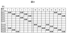
- FIG. 3 is a diagram (301) showing the timing of disposal and installation of the reaction vessel. It is assumed that the reaction promotion unit 108 has 64 holding positions, and the timing of disposal and installation of the reaction vessel with respect to the holding positions (positions 1 to 64) in the operation cycle of the apparatus is shown. In the operation cycle 1, the consumables transfer unit 112 executes the disposal operation of the reaction vessel for the position 1 located at the disposal position 202, and in the operation cycle 4 three cycles later, the consumables transfer unit 112 is installed. The reaction vessel installation operation is executed for the position 1 moved to the position 201. By repeating regular operations of the reaction promoting unit 108 and the consumables transport unit 112 according to the operation cycle, the holding position reaching the installation position must be such that the reaction vessel is disposed of before the predetermined cycle. become.
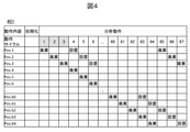
- FIG. 4 shows the operation of the consumables transport unit 112 at the start of the analysis operation.
- This time chart is premised on the automatic analyzer shown in FIG. 3, which requires three operation cycles for the holding position located at the disposal position 202 to move to the installation position 201.
- the consumables transfer unit 112 does not install the reaction vessel.
- the installation of the reaction vessel is started from the operation cycle 4, and since the disposal operation of the position 1 located at the installation position 201 at this time is performed before the 3 operation cycles, the reaction vessel is set to the position 1 after the end of the previous analysis operation.
- the consumables transport unit 112 continuously installs and disposes of the reaction vessel.
- the reaction vessel is installed at the position 1 and the reaction vessel is discarded at the position 4.
- the consumables transport unit 112 first transports and installs a new reaction vessel at the holding position located at the installation position 201, and then disposes of it as it is without returning to the home position. It is preferable to move to 202, take out the reaction vessel installed in the holding position located at the disposal position 202, transport it to the disposal section, and dispose of it. This makes it possible to easily perform the installation operation and the disposal operation of the reaction vessel with one consumables transport unit in one operation cycle. As a result, it is not necessary to mount a consumables transport unit for each of the installation and disposal of the reaction vessel, and it is possible to optimize the mechanism arrangement and reduce the equipment cost.
- the reaction vessel being measured is discarded by defining and managing the state for each holding position on the reaction promotion unit. It makes it possible to determine which reaction vessel should not be used.
- the temperature of the reaction vessel holding the reaction solution being measured, the sample, and the reagent are raised.
- the reaction vessel held for this purpose reaches the disposal position 202 after a predetermined operation cycle has elapsed. If these reaction vessels are discarded even though the analysis has not been completed, there are problems such as interruption of measurement and loss of the sample or reagent being analyzed. Therefore, in this embodiment, we propose an automatic analyzer that can determine the reaction vessel that should not be discarded, such as the reaction vessel being measured, by defining the state for each holding position of the reaction promotion unit 108.
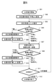
- FIG. 5 is a flowchart for determining the reaction container installation and disposal operation of the consumables transport unit 112 executed by the control device 115.
- the control device 115 sets the states (referred to as "positional states") of all the holding positions on the reaction promotion unit 108 to "unknown” (step). 502).
- the position state "unknown” means that it is unknown that the reaction vessel is arranged at the holding position.
- the reaction promotion unit 108 operates (step 503)
- the holding position accessed by the consumables transport unit 112 is updated.
- the consumables transport unit 112 confirms the position state of the holding position located at the updated installation position 201 (step 504).
- the consumables transport unit 112 installs the reaction vessel at the holding position located at the installation position 201 (step 505), and the consumables transport unit 112 is at the holding position.
- the position state is changed to "Yes” (step 506).
- the position state "Yes” indicates that the reaction vessel installed at the holding position is the reaction vessel installed in this analysis operation.
- step 504 when the position state of the installation position 201 is confirmed (step 504), if the position state is other than "none", that is, “unknown”, “yes”, “in use”, or “disposable”, the installation position.
- the consumables transport unit 112 moves to the disposal position without doing anything about 201 (step 507). Similar to step 504, the consumables transport unit 112 confirms the position state of the holding position located at the disposal position 202 (step 508). When the position state of the holding position reaching the disposal position 202 is "unknown” or "disposable”, the consumables transport unit 112 discards the reaction vessel from the disposal position 202 (step 509), and the position of the holding position. Change the state to "none" (step 510).
- step 508 when the position status of the disposal position 202 is confirmed (step 508), if the position status is other than "unknown” or “disposable", that is, “none", “yes”, or “in use”, the disposal position For 202, the process proceeds to the analysis end determination (step 511) without doing anything. In the analysis end determination (step 511), it is determined whether to continue or end the analysis. When continuing the analysis, the process returns to the operation of the reaction promotion unit 108 (step 503), and when the analysis is completed, the analysis end operation is executed (step 512), and the analysis operation is ended.
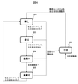
- FIG. 6 is a transition diagram of the position state of the reaction promotion unit 108 at each holding position. Regardless of the actual state of the position state when the automatic analyzer is started and the analysis operation by the device is started, the position state of all the holding positions is set to "unknown” (601). When the reaction vessel is disposed of at a certain holding position by the consumables transport unit 112, the position state is changed to "none" (602). In the case of "unknown", the consumables transport unit 112 executes the disposal operation of the reaction vessel regardless of the actual presence or absence of the reaction vessel at the holding position.
- the sample or reagent is dispensed into the reaction vessel in the holding position where the position state is "Yes” by the sample dispensing unit 105 or the reagent dispensing unit 106, so that the position state becomes "in use” (604). Transition.
- the consumables transport unit 112 cannot perform the installation operation and the disposal operation of the reaction vessel. It is permissible for the sample dispensing unit or reagent dispensing unit to perform the required dispensing operation.
- the reaction vessel in the holding position where the position state is “in use” (604) shifts to "disposable” (605) after the holding period in the reaction promotion unit 108 such as the end of measurement or the end of temperature rise. do.
- the consumables transport unit 112 can execute the disposal operation of the reaction vessel for the reaction vessel in the holding position of the position state "disposable” (605), but cannot execute the installation operation of the reaction vessel. Note The unit's dispensing operation cannot also be performed.
- the position state changes to “none” (602).
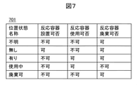
- FIG. 7 is a diagram (701) summarizing whether or not it can be installed, whether or not it can be used, and whether or not it can be disposed of for each position.
- the control device 115 confirms the position and state of the holding position accessed by the consumables transport unit 112, and determines whether or not the reaction vessel can be disposed of, whether or not it can be used, or whether or not it can be installed. If it is determined that the operation is not possible, the operation is controlled so as to skip the operation.
- the consumables transport unit 112 can determine the permissible operation with respect to the holding position. For example, the reaction vessel is being re-installed at the holding position where the reaction vessel is already installed, or the reaction vessel is being measured. It is possible to reduce the risk of discarding the reaction vessel holding the reaction solution in the middle of measurement or performing an erroneous dispensing operation.
- This embodiment is a particularly effective configuration for a composite automated analyzer that realizes multiple measurements with one unit.
- one mechanism may be shared by a plurality of measurement systems in order to optimize the mechanism arrangement and reduce the equipment cost. For example, when the reaction promotion unit 108 is shared by a plurality of measurement systems, there is a high risk that erroneous processing will be performed only by the operation sequence.
- the present invention is not limited to the above-described embodiment, but includes various modifications.
- the above-mentioned examples have been described in detail in order to explain the present invention in an easy-to-understand manner, and are not necessarily limited to those having all the described configurations. Further, it is possible to add a part of the configuration of a certain embodiment to the configuration of another embodiment, and it is possible to add, delete, replace, etc. another configuration with respect to a part of the configuration of each embodiment. Is.
- 100 Automatic analyzer, 101 ... Specimen container, 102 ... Specimen transfer unit, 103 ... Reagent container, 104 ... Reagent storage unit, 105 ... Specimen dispensing unit, 106 ... -Reagent dispensing unit, 107 ... Stirring unit, 108 ... Reaction promotion unit, 109 ... Measurement unit, 110 ... Specimen suction position, 111 ... Consumables storage unit, 112 ... Consumable Product transfer unit, 113 ... Reagent dispensing nozzle cleaning unit, 114 ... Stirring rod cleaning unit, 115 ... Control device, 201 ... Installation position, 202 ... Disposal position.
Landscapes
- Chemical & Material Sciences (AREA)
- Physics & Mathematics (AREA)
- Health & Medical Sciences (AREA)
- Life Sciences & Earth Sciences (AREA)
- Analytical Chemistry (AREA)
- Biochemistry (AREA)
- General Health & Medical Sciences (AREA)
- General Physics & Mathematics (AREA)
- Immunology (AREA)
- Pathology (AREA)
- Chemical Kinetics & Catalysis (AREA)
- Automatic Analysis And Handling Materials Therefor (AREA)
Abstract
Description
Claims (9)
- 反応容器が配置される保持位置を複数有する反応促進ユニットと、
前記反応促進ユニットの第1位置及び第2位置にアクセスする消耗品搬送ユニットとを有し、
前記反応促進ユニットは、動作サイクルごとに規則正しく動作し、第1動作サイクル時に前記第2位置に位置する保持位置は、n(n:整数)動作サイクル後に前記第1位置に移動し、
前記第1位置は、前記消耗品搬送ユニットが上記反応促進ユニットに反応容器を設置する位置であり、前記第2位置は、前記消耗品搬送ユニットが上記反応促進ユニットから反応容器を廃棄する位置であり、
前記消耗品搬送ユニットは、前記第1~第n動作サイクルまでは、動作サイクルごとに、前記第1位置への反応容器の設置動作を行うことなく、前記第2位置からの反応容器の廃棄動作を行い、第(n+1)動作サイクル以降は、動作サイクルごとに、前記第1位置への反応容器の設置動作と前記第2位置からの反応容器の廃棄動作とを行う自動分析装置。 - 請求項1において、
前記消耗品搬送ユニットは、前記第(n+1)動作サイクル以降は、動作サイクルごとに、新規の反応容器を前記第1位置へ搬送し、前記第1位置に位置する保持位置に前記新規の反応容器を設置した後、前記第2位置へ移動し、前記第2位置に位置する保持位置に設置された反応容器を取り出し、廃棄部に搬送して廃棄する自動分析装置。 - 請求項1において、
前記反応促進ユニットは、円周上に反応容器を設置し、動作サイクルごとに所定量の回転動作を行う自動分析装置。 - 反応容器が配置される保持位置を複数有する反応促進ユニットと、
前記反応促進ユニットの第1位置及び第2位置にアクセスする消耗品搬送ユニットと、
前記反応促進ユニットの保持位置ごとの位置状態を管理する制御装置とを有し、
前記位置状態には、反応容器が配置されていることが不明であることを示す第1状態、反応容器が配置されていないことを示す第2状態とを含み、
前記第1位置は、前記消耗品搬送ユニットが上記反応促進ユニットに反応容器を設置する位置であり、前記第2位置は、前記消耗品搬送ユニットが上記反応促進ユニットから反応容器を廃棄する位置であり、
前記消耗品搬送ユニットは、前記第1位置に位置する保持位置の位置状態が前記第2状態であるときに反応容器の設置動作を行い、前記第2位置に位置する保持位置の位置状態が前記第1状態であるときに反応容器の廃棄動作を行う自動分析装置。 - 請求項4において、
前記制御装置は、分析動作開始時に、前記反応促進ユニットの全ての保持位置の位置状態を前記第1状態とする自動分析装置。 - 請求項5において、
前記消耗品搬送ユニットは、動作サイクルごとに、前記第1位置に位置する保持位置が前記第2状態であるときに新規の反応容器を前記第1位置へ搬送し、前記第1位置に位置する保持位置に前記新規の反応容器を設置した後、前記第2位置へ移動し、前記第2位置に位置する保持位置の位置状態が前記第1状態であるときに前記第2位置に位置する保持位置に設置された反応容器を取り出し、廃棄部に搬送して廃棄する自動分析装置。 - 請求項6において、
前記制御装置は、前記消耗品搬送ユニットが反応容器の設置動作をおこなった保持位置の位置状態を前記第2状態から第3状態に遷移させ、前記消耗品搬送ユニットが反応容器の廃棄動作をおこなった保持位置の位置状態を前記第2状態に遷移させる自動分析装置。 - 請求項7において、
前記制御装置は、前記第3状態である保持位置の位置状態を、設置された反応容器に分注ユニットが分注動作を行ったことにより第4状態に遷移させ、前記第4状態である保持位置の位置状態を、前記反応促進ユニットにおける保持期間の終了により第5状態に遷移させる自動分析装置。 - 請求項8において、
前記消耗品搬送ユニットは、さらに前記第2位置に位置する保持位置の位置状態が前記第5状態であるときに反応容器の廃棄動作を行う自動分析装置。
Priority Applications (4)
| Application Number | Priority Date | Filing Date | Title |
|---|---|---|---|
| CN202180045228.0A CN115715370A (zh) | 2020-07-28 | 2021-02-10 | 自动分析装置 |
| EP21850032.0A EP4191250A1 (en) | 2020-07-28 | 2021-02-10 | Automatic analysis device |
| US18/011,609 US20230280362A1 (en) | 2020-07-28 | 2021-02-10 | Automatic Analyzer |
| JP2022539997A JP7395754B2 (ja) | 2020-07-28 | 2021-02-10 | 自動分析装置 |
Applications Claiming Priority (2)
| Application Number | Priority Date | Filing Date | Title |
|---|---|---|---|
| JP2020127063 | 2020-07-28 | ||
| JP2020-127063 | 2020-07-28 |
Publications (1)
| Publication Number | Publication Date |
|---|---|
| WO2022024424A1 true WO2022024424A1 (ja) | 2022-02-03 |
Family
ID=80037925
Family Applications (1)
| Application Number | Title | Priority Date | Filing Date |
|---|---|---|---|
| PCT/JP2021/004933 WO2022024424A1 (ja) | 2020-07-28 | 2021-02-10 | 自動分析装置 |
Country Status (5)
| Country | Link |
|---|---|
| US (1) | US20230280362A1 (ja) |
| EP (1) | EP4191250A1 (ja) |
| JP (1) | JP7395754B2 (ja) |
| CN (1) | CN115715370A (ja) |
| WO (1) | WO2022024424A1 (ja) |
Citations (7)
| Publication number | Priority date | Publication date | Assignee | Title |
|---|---|---|---|---|
| JPH0688826A (ja) * | 1992-06-16 | 1994-03-29 | Hitachi Ltd | 自動分析装置 |
| JPH07270427A (ja) * | 1994-03-31 | 1995-10-20 | Shimadzu Corp | 血液凝固測定装置 |
| JPH11223633A (ja) * | 1987-12-19 | 1999-08-17 | Olympus Optical Co Ltd | 化学分析方法 |
| JP2009281847A (ja) * | 2008-05-22 | 2009-12-03 | Sysmex Corp | 分析装置 |
| JP2013036756A (ja) * | 2011-08-03 | 2013-02-21 | Sysmex Corp | 検体分析装置 |
| WO2018155049A1 (ja) * | 2017-02-22 | 2018-08-30 | 株式会社 日立ハイテクノロジーズ | 自動分析装置 |
| WO2020235134A1 (ja) * | 2019-05-21 | 2020-11-26 | 株式会社日立ハイテク | 自動分析装置 |
Family Cites Families (1)
| Publication number | Priority date | Publication date | Assignee | Title |
|---|---|---|---|---|
| JP7270427B2 (ja) | 2019-03-18 | 2023-05-10 | 株式会社Nttファシリティーズ | 建物健全性検証システム、建物健全性検証方法、および建物健全性検証システムの製造方法 |
-
2021
- 2021-02-10 EP EP21850032.0A patent/EP4191250A1/en active Pending
- 2021-02-10 US US18/011,609 patent/US20230280362A1/en active Pending
- 2021-02-10 WO PCT/JP2021/004933 patent/WO2022024424A1/ja active Application Filing
- 2021-02-10 CN CN202180045228.0A patent/CN115715370A/zh active Pending
- 2021-02-10 JP JP2022539997A patent/JP7395754B2/ja active Active
Patent Citations (7)
| Publication number | Priority date | Publication date | Assignee | Title |
|---|---|---|---|---|
| JPH11223633A (ja) * | 1987-12-19 | 1999-08-17 | Olympus Optical Co Ltd | 化学分析方法 |
| JPH0688826A (ja) * | 1992-06-16 | 1994-03-29 | Hitachi Ltd | 自動分析装置 |
| JPH07270427A (ja) * | 1994-03-31 | 1995-10-20 | Shimadzu Corp | 血液凝固測定装置 |
| JP2009281847A (ja) * | 2008-05-22 | 2009-12-03 | Sysmex Corp | 分析装置 |
| JP2013036756A (ja) * | 2011-08-03 | 2013-02-21 | Sysmex Corp | 検体分析装置 |
| WO2018155049A1 (ja) * | 2017-02-22 | 2018-08-30 | 株式会社 日立ハイテクノロジーズ | 自動分析装置 |
| WO2020235134A1 (ja) * | 2019-05-21 | 2020-11-26 | 株式会社日立ハイテク | 自動分析装置 |
Also Published As
| Publication number | Publication date |
|---|---|
| EP4191250A1 (en) | 2023-06-07 |
| US20230280362A1 (en) | 2023-09-07 |
| CN115715370A (zh) | 2023-02-24 |
| JPWO2022024424A1 (ja) | 2022-02-03 |
| JP7395754B2 (ja) | 2023-12-11 |
Similar Documents
| Publication | Publication Date | Title |
|---|---|---|
| JP7218458B2 (ja) | 自動分析装置及び自動分析方法 | |
| JP6320535B2 (ja) | 自動分析装置 | |
| US5289385A (en) | Adaptive scheduling system and method for operating a biological sample analyzer with variable rinsing | |
| CN110023765B (zh) | 自动分析装置 | |
| JP2008209338A (ja) | 自動分析装置 | |
| JP2008281453A (ja) | 自動分析システム | |
| JP2005214683A (ja) | 自動分析装置 | |
| JPWO2010117045A1 (ja) | 自動分析装置 | |
| JP2009036723A (ja) | 自動分析装置および動作環境設定方法 | |
| JP2004028931A (ja) | 自動分析システム | |
| WO2017138285A1 (ja) | 自動分析装置 | |
| WO2022024424A1 (ja) | 自動分析装置 | |
| EP3896454B1 (en) | Automated analyzer | |
| US20210215728A1 (en) | Automatic Analyzer | |
| WO2010004789A1 (ja) | 自動分析装置 | |
| WO2019176296A1 (ja) | 自動分析装置 | |
| JP2019211329A (ja) | 自動分析装置 | |
| CN113272653B (zh) | 自动分析装置、自动分析系统以及检体的自动分析方法 | |
| US11579159B2 (en) | Automatic analysis device | |
| JP4491505B2 (ja) | 自動分析装置 | |
| JP2005201771A (ja) | 自動分析装置 |
Legal Events
| Date | Code | Title | Description |
|---|---|---|---|
| 121 | Ep: the epo has been informed by wipo that ep was designated in this application |
Ref document number: 21850032 Country of ref document: EP Kind code of ref document: A1 |
|
| ENP | Entry into the national phase |
Ref document number: 2022539997 Country of ref document: JP Kind code of ref document: A |
|
| WWE | Wipo information: entry into national phase |
Ref document number: 2021850032 Country of ref document: EP |
|
| ENP | Entry into the national phase |
Ref document number: 2021850032 Country of ref document: EP Effective date: 20230228 |
|
| NENP | Non-entry into the national phase |
Ref country code: DE |