WO2022019311A1 - 金属箔のレーザ切断方法 - Google Patents
金属箔のレーザ切断方法 Download PDFInfo
- Publication number
- WO2022019311A1 WO2022019311A1 PCT/JP2021/027216 JP2021027216W WO2022019311A1 WO 2022019311 A1 WO2022019311 A1 WO 2022019311A1 JP 2021027216 W JP2021027216 W JP 2021027216W WO 2022019311 A1 WO2022019311 A1 WO 2022019311A1
- Authority
- WO
- WIPO (PCT)
- Prior art keywords
- laser
- metal foil
- laser beam
- laser cutting
- less
- Prior art date
- Legal status (The legal status is an assumption and is not a legal conclusion. Google has not performed a legal analysis and makes no representation as to the accuracy of the status listed.)
- Ceased
Links
Images


Classifications
-
- B—PERFORMING OPERATIONS; TRANSPORTING
- B23—MACHINE TOOLS; METAL-WORKING NOT OTHERWISE PROVIDED FOR
- B23K—SOLDERING OR UNSOLDERING; WELDING; CLADDING OR PLATING BY SOLDERING OR WELDING; CUTTING BY APPLYING HEAT LOCALLY, e.g. FLAME CUTTING; WORKING BY LASER BEAM
- B23K26/00—Working by laser beam, e.g. welding, cutting or boring
- B23K26/02—Positioning or observing the workpiece, e.g. with respect to the point of impact; Aligning, aiming or focusing the laser beam
- B23K26/06—Shaping the laser beam, e.g. by masks or multi-focusing
- B23K26/062—Shaping the laser beam, e.g. by masks or multi-focusing by direct control of the laser beam
- B23K26/0622—Shaping the laser beam, e.g. by masks or multi-focusing by direct control of the laser beam by shaping pulses
-
- B—PERFORMING OPERATIONS; TRANSPORTING
- B23—MACHINE TOOLS; METAL-WORKING NOT OTHERWISE PROVIDED FOR
- B23K—SOLDERING OR UNSOLDERING; WELDING; CLADDING OR PLATING BY SOLDERING OR WELDING; CUTTING BY APPLYING HEAT LOCALLY, e.g. FLAME CUTTING; WORKING BY LASER BEAM
- B23K26/00—Working by laser beam, e.g. welding, cutting or boring
- B23K26/08—Devices involving relative movement between laser beam and workpiece
- B23K26/082—Scanning systems, i.e. devices involving movement of the laser beam relative to the laser head
-
- B—PERFORMING OPERATIONS; TRANSPORTING
- B23—MACHINE TOOLS; METAL-WORKING NOT OTHERWISE PROVIDED FOR
- B23K—SOLDERING OR UNSOLDERING; WELDING; CLADDING OR PLATING BY SOLDERING OR WELDING; CUTTING BY APPLYING HEAT LOCALLY, e.g. FLAME CUTTING; WORKING BY LASER BEAM
- B23K26/00—Working by laser beam, e.g. welding, cutting or boring
- B23K26/36—Removing material
- B23K26/38—Removing material by boring or cutting
-
- H—ELECTRICITY
- H01—ELECTRIC ELEMENTS
- H01M—PROCESSES OR MEANS, e.g. BATTERIES, FOR THE DIRECT CONVERSION OF CHEMICAL ENERGY INTO ELECTRICAL ENERGY
- H01M4/00—Electrodes
- H01M4/02—Electrodes composed of, or comprising, active material
- H01M4/64—Carriers or collectors
- H01M4/66—Selection of materials
- H01M4/661—Metal or alloys, e.g. alloy coatings
-
- B—PERFORMING OPERATIONS; TRANSPORTING
- B23—MACHINE TOOLS; METAL-WORKING NOT OTHERWISE PROVIDED FOR
- B23K—SOLDERING OR UNSOLDERING; WELDING; CLADDING OR PLATING BY SOLDERING OR WELDING; CUTTING BY APPLYING HEAT LOCALLY, e.g. FLAME CUTTING; WORKING BY LASER BEAM
- B23K2101/00—Articles made by soldering, welding or cutting
- B23K2101/34—Coated articles, e.g. plated or painted; Surface treated articles
-
- Y—GENERAL TAGGING OF NEW TECHNOLOGICAL DEVELOPMENTS; GENERAL TAGGING OF CROSS-SECTIONAL TECHNOLOGIES SPANNING OVER SEVERAL SECTIONS OF THE IPC; TECHNICAL SUBJECTS COVERED BY FORMER USPC CROSS-REFERENCE ART COLLECTIONS [XRACs] AND DIGESTS
- Y02—TECHNOLOGIES OR APPLICATIONS FOR MITIGATION OR ADAPTATION AGAINST CLIMATE CHANGE
- Y02E—REDUCTION OF GREENHOUSE GAS [GHG] EMISSIONS, RELATED TO ENERGY GENERATION, TRANSMISSION OR DISTRIBUTION
- Y02E60/00—Enabling technologies; Technologies with a potential or indirect contribution to GHG emissions mitigation
- Y02E60/10—Energy storage using batteries
Definitions
- the present invention relates to a method for cutting a metal foil by laser.
- Laser cutting by irradiation with laser light is known as one of the methods for cutting a processing target made of a metal material.
- Laser cutting is a method of irradiating a portion to be cut with a laser beam and melting the portion with the energy of the laser beam to cut the portion to be processed (see, for example, Non-Patent Document 1).
- the object to be processed is a metal leaf
- the metal leaf is easily deformed or torn. Therefore, if various parameters for laser cutting are set in the same manner as for a thicker metal member, it may be difficult to obtain the required quality. there were.
- one of the problems of the present invention is, for example, to obtain a new and improved laser cutting method for a metal foil capable of laser cutting a metal foil to be processed.
- the surface of the metal foil to be processed is laser-cut by intermittently irradiating the surface of the metal foil with a pulse of laser light at a frequency of 1 [MHz] or less.
- the duty ratio Rd [%] represented by may be 0.1 or more and 80 or less.
- the duty ratio Rd [%] may be 0.2 or more and 40 or less.
- the pulse ratio Rp represented by is 1 or more and 7 or less, the M2 beam quality of the laser beam is 1.2 or less, and the energy irradiated by the pulse is 0.1 [mJ] or more. May be good.
- the laser beam is swept relative to the surface, the sweep rate of the laser beam is C [m / s], and the laser beam on the surface.
- the spot diameter is D [m] and the output of the laser beam is E [W]
- the following formula I A ⁇ B ⁇ C ⁇ D ⁇ E ... (3)
- the index I represented by may be 1.0 ⁇ 10 -7 or more and 1.0 ⁇ 10 -1 or less.
- the thickness of the processing target may be 500 [ ⁇ m] or less.
- the metal foil has a coated portion covered with a coating film and an exposed portion not covered with the coating film, and the coated portion and the exposed portion are swept by the laser beam. And may be continuously laser cut.
- the spot diameter of the laser beam on the surface may be 100 [ ⁇ m] or less.
- the spot diameter may be 50 [ ⁇ m] or less.
- the pulse has a first peak and a second peak after the first peak, and the output Pp2 of the first peak is the output Pp1 of the second peak.
- the processing target may be laser-cut by performing the sweeping of the laser light on the surface a plurality of times.
- each sweep in the plurality of sweeps of the laser beam may be executed under the condition that the processing target cannot be cut by one sweep.
- the sweep speed of the laser beam is C [m / s]
- the spot diameter of the laser beam on the surface is D [m]
- the output of the laser beam is E [W]
- the following equation I A ⁇ B ⁇ C ⁇ D ⁇ E ... (3)
- the thickness is 100 [ ⁇ m].
- the above-mentioned processing target may be laser-cut.
- the laser cutting method for the metal foil may include a step of removing the coating substance on the surface by irradiating the surface with a laser beam before the step of laser cutting the processing target.
- the laser light may be swept by the same path on the surface in the step of removing the coating substance on the surface and the step of laser cutting the processing target.
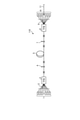
- FIG. 1 is an exemplary schematic configuration diagram of the laser cutting apparatus of the first embodiment.
- FIG. 2 is an exemplary schematic configuration diagram of a laser device included in the laser cutting device of the first embodiment.
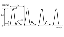
- FIG. 3 is a timing chart showing an example of a change over time in the output of the laser beam emitted from the laser cutting apparatus of the first embodiment.
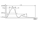
- FIG. 4 is an enlarged view showing one pulse of the laser beam of FIG.
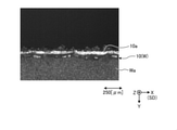
- FIG. 5 is an image taken in a plan view of an example of a cut edge of a metal leaf having a thickness of 100 [ ⁇ m] as a processing target cut by the laser cutting device of the embodiment and its vicinity.
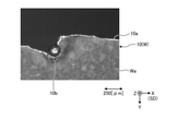
- FIG. 6 is a side view image of the cut edge of the metal foil of FIG. As a reference example, FIG.
- FIG. 7 is an image taken in a plan view of an example of a cut edge and its vicinity when the same metal leaf as in FIGS. 5 and 6 is laser-cut under conditions different from those in FIGS. 5 and 6.
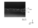
- FIG. 8 is a side view image of the cut edge of the metal foil of FIG. 7.
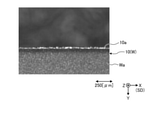
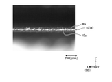
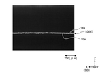
- FIG. 9 is an image taken in a plan view of an example of a cut edge of a metal leaf having a thickness of 10 [ ⁇ m] as a processing target cut by the laser cutting device of the embodiment and its vicinity.
- FIG. 10 is a photographed image of the cut edge of the metal foil of FIG. 9 in a side view.
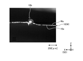
- FIG. 11 is an image taken in a plan view of an example of a cut edge and its vicinity when the same metal leaf as in FIGS.
- FIG. 9 and 10 is laser-cut under conditions different from those in FIGS. 9 and 10.
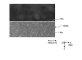
- FIG. 12 is a photographed image of the cut edge of the metal foil of FIG. 11 in a side view.
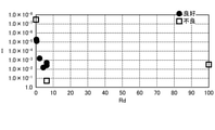
- FIG. 13 is a graph showing the experimental results of laser cutting according to the duty ratio and the index for a plurality of metal leaf samples.
- FIG. 14 is an exemplary schematic configuration diagram of the laser cutting device of the second embodiment.
- the X direction is represented by an arrow X
- the Y direction is represented by an arrow Y
- the Z direction is represented by an arrow Z.
- the X, Y, and Z directions intersect and are orthogonal to each other.
- the Z direction is the normal direction of the surface Wa (processed surface) of the processing target W.
- the X direction is exemplified as the sweep direction SD, but the sweep direction SD may intersect with the Z direction and is not limited to the X direction.
- FIG. 1 is a schematic configuration diagram of the laser cutting device 100 of the first embodiment.
- the laser cutting device 100 includes a laser device 110, an optical head 120, an optical fiber 130 connecting the laser device 110 and the optical head 120, and a controller 140.
- the processing target W of the laser cutting device 100 is made of, for example, a conductive metal material.
- the metal material is, for example, a copper-based material such as copper or a copper alloy, or an aluminum-based material such as aluminum or an aluminum alloy.
- the processing target W may also be referred to as a metal conductor.
- the processing target W is, for example, a metal foil 10 having a thickness of 500 [ ⁇ m] or less, but the processing target W is not limited to this.
- the metal leaf 10 may be an electrode of a battery such as a lithium ion battery.
- the metal leaf 10 may be coated with an active material such as manganese dioxide or lithium.
- the laser cutting device 100 may continuously cut both the portion coated with the active material and the portion not coated with the active material by one sweep.
- the active material may also be referred to as a coating film, a coating film, a coating substance, a surface layer, or a surface layer material.
- the metal leaf 10 as the processing target W of the laser cutting device 100 is not limited to the electrode of the battery, and may be coated with a substance different from the active material, for example, or the plating layer.
- Such a surface layer may be formed, a coating or a surface layer may be formed over the entire surface, or a portion where the coating or the surface layer is formed and a portion where the coating or the surface layer is not formed. It may have and may have no coating or surface layer.
- the laser device 110 is provided with a laser oscillator, and as an example, it is configured to be able to output a single mode laser beam having a power of several kW.
- the laser device 110 will be described later.
- the optical fiber 130 guides the laser light output from the laser device 110 to the optical head 120.
- the optical fiber 130 is configured to propagate the single-mode laser beam.
- M 2 beam quality of the single-mode laser light is set to 1.2 or less.
- the optical fiber 130 is configured to propagate the multimode laser beam.
- the optical head 120 is an optical device for irradiating the processing target W with the laser beam input from the laser device 110.
- the optical head 120 includes a collimating lens 121 and a condenser lens 122.
- the collimating lens 121 and the condenser lens 122 may also be referred to as optical components.
- the optical head 120 may have optical components other than the collimating lens 121 and the condenser lens 122.
- the optical head 120 is configured to be able to change the relative position with the processing target W because the laser light L is swept while irradiating the processing target W with the laser light L.
- the relative movement between the optical head 120 and the processing target W can be realized by the movement of the optical head 120, the movement of the processing target W, or the movement of both the optical head 120 and the processing target W.
- the collimating lens 121 collimates the input laser beam.
- the collimated laser beam becomes parallel light.
- the condenser lens 122 concentrates the laser light as parallel light and irradiates the processing target W as the laser light L (output light).
- the optical head 120 irradiates the surface Wa of the processing target W with the laser beam L in the direction opposite to the Z direction.
- the irradiation direction of the laser beam L from the optical head 120 is opposite to the Z direction.
- the optical head 120 can collect the laser beam L so that the beam diameter is, for example, 10 [ ⁇ m] or more.
- the controller 140 controls the operation of the laser device 110 and the operation of the optical head 120 or the drive mechanism of the stage that supports the processing target W.
- FIG. 2 is a schematic configuration diagram of an example of the laser device 110.
- the laser device 110 may also be referred to as a light source device.
- the laser device 110 in FIG. 2 is a CW laser capable of continuously outputting laser light.
- the laser device 110 may also be referred to as a laser oscillator.
- the laser device 110 exemplified in FIG. 2 is an optical fiber laser, which includes a plurality of semiconductor excitation light sources 1, a plurality of optical fibers 2, an optical combiner 3, an optical fiber plug grating (FBG) 4, and amplification. It includes an optical fiber 5, an FBG 7, an optical combiner 8, a plurality of optical fibers 9, a plurality of semiconductor excitation light sources 6, and an output optical fiber 11. Each element is appropriately connected by an optical fiber.
- the output optical fiber 11 is optically coupled to the optical fiber 130 shown in FIG. 1 or is a part (input end) of the optical fiber 130.
- Each of the plurality of semiconductor excitation light sources 1 as an excitation light source outputs the excitation light supplied to the amplification optical fiber 5.
- the excitation light has a wavelength capable of photoexciting the amplification optical fiber 5, for example, a wavelength of 915 [nm].
- Each of the plurality of optical fibers 2 propagates the excitation light output from each semiconductor excitation light source 1 and outputs the excitation light to the optical combiner 3.
- the optical combiner 3 is composed of TFB (tapered fiber bundle) in this embodiment.
- the optical combiner 3 combines the excitation light input from each optical fiber 2 with the optical fiber of the signal optical port and outputs the excitation light to the amplification optical fiber 5.
- the amplification optical fiber 5 is a YDF (ytterbium doped fiber) in which ytterbium (Yb) ion, which is an amplifying substance, is added to a core portion made of quartz glass, and the outer periphery of the core portion is made of quartz glass. It is a double clad type optical fiber in which the inner clad layer formed and the outer clad layer made of resin or the like are sequentially formed.
- the core portion of the amplification optical fiber 5 has an NA of, for example, 0.08, and is configured to propagate Yb ion emission, for example, light having a wavelength of 1070 [nm] in a single mode.
- the absorption coefficient of the core portion of the amplification optical fiber 5 is, for example, 200 [dB / m] at a wavelength of 915 [nm]. Further, the power conversion efficiency from the excitation light input to the core portion to the laser oscillation light is, for example, 70%.
- the FBG 4 which is the rear end side reflecting means is connected between the optical fiber of the signal optical port of the optical combiner 3 and the optical fiber 5 for amplification.
- the FBG4 has a center wavelength of, for example, 1070 [nm], a reflectance in a wavelength band having a width of about 2 [nm] in and around the center wavelength of about 100%, and almost all light having a wavelength of 915 [nm] is transmitted. do.
- the FBG 7 which is an output side reflecting means is connected between the optical fiber of the signal optical port of the optical combiner 8 and the optical fiber 5 for amplification.
- the FBG7 has a center wavelength of, for example, 1070 [nm], which is substantially the same as that of the FBG4, has a reflectance of about 10% to 30% at the center wavelength, and has a full width at half maximum of the reflection wavelength band of about 1 [nm]. Most of the light having a wavelength of 915 [nm] is transmitted.
- the FBGs 4 and 7 are arranged for each of both ends of the optical fiber 5 for amplification, and form an optical fiber resonator for light having a wavelength of 1070 [nm].
- Each of the plurality of semiconductor excitation light sources 6 as the excitation light source outputs the excitation light supplied to the amplification optical fiber 5.
- the excitation light has a wavelength capable of photoexciting the amplification optical fiber 5, for example, a wavelength of 915 [nm].
- Each of the plurality of optical fibers 9 propagates the excitation light output from each semiconductor excitation light source 6 and outputs the excitation light to the optical combiner 8.
- the optical combiner 8 is composed of a TFB in this embodiment.
- the optical combiner 8 combines the excitation light input from each optical fiber 9 with the optical fiber of the signal optical port and outputs the excitation light to the amplification optical fiber 5.
- Yb ions in the core portion are photoexcited by the excitation light, and light in a band including a wavelength of 1070 [nm] is emitted.
- the light emission having a wavelength of 1070 [nm] is laser-oscillated by the optical amplification action of the amplification optical fiber 5 and the action of the optical resonator composed of the FBGs 4 and 7.
- the output optical fiber 11 is arranged on the opposite side of the FBG 7 and is connected to the optical fiber of the signal optical port of the optical combiner 8.
- the oscillated laser light (laser oscillated light) is output from the output optical fiber 11.
- the laser device 110 operates as a pulse laser that outputs a pulse of laser light under the control of a controller 140 as described later.
- the laser device 110 may be a pulse laser that generates a pulse by another method or a laser device having an optical amplification method different from that of an optical fiber laser.
- the processing target W is set so as to be irradiated with the laser beam L. Then, in a state where the laser beam L is irradiated on the processing target W, the laser light L and the processing target W move relatively. As a result, the laser beam L moves (sweeps) in the sweep direction SD on the surface Wa while being irradiated on the surface Wa. The portion irradiated with the laser beam L is melted and cut.
- FIG. 3 is a timing chart showing a change over time in the power of the laser beam L
- FIG. 4 is an enlarged view of a part (1 pulse) of FIG.
- the pulse frequency of the laser beam L (1 / A, A: pulse period [s], see FIGS. 3 and 4) is 6 [KHz] or more and 1 [MHz] or less. It was found that is suitable.
- the controller 140 controls the laser device 110 so that it is switched on and off, that is, between an output state (operating state) and a stopped state (non-output state, non-operating state) at a high frequency as described above.
- the controller 140 outputs a control signal so that power having a rectangular wave shape is supplied to the semiconductor excitation light sources 1 and 6 in time.
- the change with time of the output of the laser beam L by the laser device 110 does not become a perfect rectangular wave, but becomes a blunt waveform as shown in FIGS. 3 and 4 as an example.
- the inventors have defined the duty ratio Rd [%] of the pulse of the laser beam L output from the laser apparatus 110 as the following equation (1).
- Rd A ⁇ B ⁇ 100 ⁇ ⁇ ⁇ (1)
- B [s] (see FIG. 4) is the full width of the half value of the pulse, and is the width (time width) of the half value (0.5 Pmax) with respect to the maximum value Pmax [W] of the pulse. If there are a plurality of times with 0.5 Pmax in one pulse, the time width is set to the farthest two hours.
- the duty ratio Rd [%] is preferably 0.1 or more and 80 or less, and more preferably 0.2 or more and 40 or less. did.
- the inventors have found a suitable range for the pulse waveform through experimental research.
- the inventors defined the pulse ratio Rp as the following equation (2).
- Rp F / B ...
- F is a pulse of 1 / e 2 width
- B is the full width at half maximum of the pulse.
- the 1 / e 2 width of a pulse is a width of a value that is 1 / e 2 ( ⁇ 0.135) with respect to the maximum value Pmax of the pulse, and there are a plurality of values that are 1 / e 2 in one pulse. In some cases, it is the time width between the two farthest hours.
- the pulse ratio Rp is an index showing the spread of the pulse, and the larger the value, the wider the pulse.
- the pulse ratio Rp is preferably 1 or more and 7 or less. Further, it was found that it is preferable that the M2 beam quality of the laser beam L is 1.2 or less and the energy irradiated by the pulse is 0.1 [mJ] or more.
- the inventors have found a suitable range for the index I represented by the following formula (3) by experimental research.
- I A x B x C x D x E ... (3)
- C [m / s] is the sweep speed of the laser beam L
- D [m] is the spot diameter on the surface Wa of the processing target W of the laser beam L
- E [W] is the output of the laser beam L.
- the spot diameter D (beam diameter) includes a peak of the power in the spot is defined as the diameter of the region of 1 / e 2 or more of the power of the peak power.
- the length of the region to be the 1 / e 2 or more of the power of the peak power can be defined as a spot diameter.
- the power distribution in the spot is not limited to the Gaussian shape. Experimental studies by the inventors have found that the index I is preferably 1.0 ⁇ 10 -7 or more and 1.0 ⁇ 10 -1 or less.
- the metal foil 10 as the processing target W is an aluminum foil having a thickness of 100 [ ⁇ m] as an electrode coated with an active material on the surface, and the duty ratio Rd is 6.1. It is an experimental result when the index I is 3.84 ⁇ 10 -3.
- FIG. 5 is a plan view showing the cutting edge 10a and its vicinity
- FIG. 6 is a side view of the cutting edge 10a. As is clear from FIGS. 5 and 6, under this condition, a good cutting edge 10a (processed state) with little or no bending, turning, dross, spatter, etc. is obtained.
- FIGS. 7 and 8 are experimental results as a reference example when the irradiation conditions of the laser beam L are changed for the same processing target W as in FIGS. 5 and 6.
- the duty ratio Rd is 100 and the index I is 3.84 ⁇ 10 -3 .
- the duty ratio Rd of 100 means continuous irradiation of the laser beam L, not intermittent irradiation of the pulsed laser beam L.
- FIG. 7 is a plan view showing the cutting edge 10a and its vicinity
- FIG. 8 is a side view of the cutting edge 10a. As will be clear by comparing FIGS. 7 and 8 with FIGS. 5 and 6, under this condition, the deformation of the cut edge 10a is larger, and the cut edge 10a is turned over or bent.
- FIGS. 9 and 10 the metal leaf 10 as the processing target W is a copper foil having a thickness of 10 [ ⁇ m], the duty ratio Rd is 6.1, and the index I is 3.84 ⁇ 10 -3 . It is an experimental result of the case.
- FIG. 9 is a plan view showing the cutting edge 10a and its vicinity
- FIG. 10 is a side view of the cutting edge 10a. As is clear from FIGS. 9 and 10, under this condition, a good cutting edge 10a (processed state) with little or no bending, turning, dross, spatter, etc. is obtained.
- FIGS. 11 and 12 are experimental results as a reference example when the irradiation conditions of the laser beam L are changed for the same processing target W as in FIGS. 9 and 10.
- the duty ratio Rd is 100 and the index I is 6.3 ⁇ 10-2 . Since the duty ratio Rd is 100, the laser beam L is continuously irradiated even in this case as well.
- FIG. 11 is a plan view showing the cutting edge 10a and its vicinity
- FIG. 12 is a side view of the cutting edge 10a. As is clear from FIGS. 11 and 12, under this condition, dross 10b is generated, and the cutting edge 10a is greatly turned up or bent.
- one metal foil 10 such as an aluminum foil or a copper foil may have a coated portion covered with a film such as an active material and an exposed portion not covered with the film. ..
- the duty ratio Rd and the index I are appropriately set according to the specifications such as the material and thickness of the metal leaf 10 and the coating film.
- a good processing state can be obtained in both the covered part and the exposed part. confirmed.
- laser cutting of the metal leaf 10 having a covered portion and an exposed portion can be performed more quickly, and by extension, a requirement for manufacturing a part or a product containing the metal foil 10. The time can be shortened.
- Sweep speed may change. Changes in sweep speed may adversely affect processing quality.
- the inventors have found that even when the sweep rate changes in continuous laser cutting, for example, the duty ratio Rd and the index I according to the sweep rate are appropriately set or changed. It was confirmed that the processed state could be obtained. According to such a method, it is possible to suppress the deterioration of the processing quality due to the change of the sweep speed, to easily secure the required processing quality, and to increase the processing yield.
- FIG. 13 is a graph showing a part of the experimental results when the horizontal axis is the duty ratio Rd and the vertical axis is the index I. From FIG. 13, it can be seen that suitable laser cutting can be performed when the duty ratio Rd and the index I are each within the predetermined ranges.
- the spot diameter (beam diameter) D is preferably 100 [ ⁇ m] or less, more preferably 50 [ ⁇ m] or less, and 30 [ ⁇ m] or less. Was found to be even more preferable. This is because if the spot diameter D is too large, heat energy is applied to the outside of the cutting region (calf), that is, the processing target W, and there is a possibility that quality defects such as oxidation due to heat may occur.
- the pulse when the pulse has a first peak P1 and a second peak P2 after the first peak P1, the first of the outputs Pp2 of the second peak P2.
- the energy required for cutting may be generated by a pulse having only one peak. May be difficult to give.
- the thermal influence on the periphery of the cutting region may become too large.
- the output ratio Ro is 0.1 or more and 0.5 or less, even for a material having a relatively high reflectance to laser light, the material is first melted by the first peak P1.
- the second peak P2 which has a lower output than the first peak P1, can secure an appropriate amount of energy required for cutting. As a result, more reliable cutting is possible, and the thermal influence on the periphery of the cutting region can be suppressed, and a good cutting edge 10a with little or no bending, turning, dross, spatter, etc. can be obtained. be able to.
- the region is irradiated with the second peak P2 having a lower output than the first peak P1 before the region melted by the first peak P1 is solidified.
- the time interval between the first peak P1 and the second peak P2 can be, for example, 5.0 [ ⁇ sec] or less.
- the machining target W is cut by executing the sweep under the condition that the cutting of the machining target W is not completed by one sweep multiple times in the same route.
- a brittle and fragile material such as ceramic or polymer, an active material or the like (hereinafter referred to as a coating substance) is coated on the surface of the processing target W, if excessive energy is applied, the coating is applied.
- the coating is applied.
- adverse effects such as cracking and evaporation on the material.
- the coated material is cracked or evaporated due to the input of excessive energy. It is possible to suppress the occurrence of such adverse effects.
- the index I is 1.0 ⁇ 10 ⁇ 2 or more and 1.0 ⁇ 10 ⁇ 5 or less. It was found that the processing target W can be cut while suppressing the adverse effect on the coated material by executing the sweep twice.
- the coating substance is removed by irradiation with a laser beam in the cutting region (planned cutting region) and its vicinity, and then the processing target W is cut by executing the sweeping of the laser light of the present embodiment described above. ..
- the laser beam may be swept by the same path in the step of removing the coating substance and the step of performing laser cutting. Further, the laser beam irradiated in the step of removing the coating substance may be a pulse or a continuous wave.
- the processing is performed by intermittently irradiating the surface Wa of the metal leaf 10 as the processing target W with a pulse of laser light L at a frequency of 1 [MHz] or less. Laser cutting the target W.
- the duty ratio Rd [%] of the pulse of the laser beam L may be 0.1 or more and 80 or less, or 0.2 or more and 40 or less.
- the pulse ratio Rp is 1 or more and 7 or less
- the M2 beam quality of the laser beam L is 1.2 or less
- the energy irradiated by the pulse is 0.1 [mJ. ] It may be more than that.
- the index I may be 1.0 ⁇ 10 -7 or more and 1.0 ⁇ 10 -1 or less.
- FIG. 14 is a schematic configuration diagram of the laser cutting device 100A of the second embodiment.
- the optical head 120 has a galvano scanner 126 between the collimating lens 121 and the condenser lens 122.
- the galvano scanner 126 has two mirrors 126a.
- the irradiation direction and irradiation position of the laser beam L change due to the change in the postures of these two mirrors 126a. That is, the laser cutting device 100A can move the irradiation position of the laser beam L and sweep the laser beam L without moving the optical head 120.
- the controller 140 can control the operation of the motor 126b corresponding to each mirror 126a so that the angle (posture) of the mirror 126a changes. The same operation and effect as those of the first embodiment can be obtained by this embodiment as well.
- the surface area of the molten pool may be adjusted by sweeping by known wobbling, weaving, output modulation, or the like.
- the processing target may be one in which another thin metal layer exists on the surface of the metal, such as a plated metal plate.
- the laser device is not limited to the CW laser, and may be, for example, a pulse laser capable of realizing intermittent irradiation at a predetermined high frequency and a duty ratio in a predetermined range.
- the present invention can be used as a laser cutting method for metal foil.
- Sweep speed D ... Spot diameter E ... Output F ... 1 / e 2 width I ... index L ... laser light
- P1 first peak
- P2 second peak
- Pp1, Pp2 ... output
- Pmax maximum value SD
- sweep direction Rd ; duty ratio
- Rp pulse ratio W ... machining target Wa ... Surface X ... Direction Y ... Direction Z ... Direction (normal direction)
Landscapes
- Physics & Mathematics (AREA)
- Optics & Photonics (AREA)
- Engineering & Computer Science (AREA)
- Plasma & Fusion (AREA)
- Mechanical Engineering (AREA)
- Chemical & Material Sciences (AREA)
- Materials Engineering (AREA)
- Chemical Kinetics & Catalysis (AREA)
- Electrochemistry (AREA)
- General Chemical & Material Sciences (AREA)
- Laser Beam Processing (AREA)
- Cell Electrode Carriers And Collectors (AREA)
- Battery Electrode And Active Subsutance (AREA)
Priority Applications (5)
| Application Number | Priority Date | Filing Date | Title |
|---|---|---|---|
| CN202180060357.7A CN116157228A (zh) | 2020-07-20 | 2021-07-20 | 金属箔的激光切断方法 |
| JP2022538028A JP7328456B2 (ja) | 2020-07-20 | 2021-07-20 | 金属箔のレーザ切断方法 |
| EP21846929.4A EP4183516A4 (en) | 2020-07-20 | 2021-07-20 | METHOD OF CUTTING A METAL SHEET BY MEANS OF A LASER |
| KR1020237001924A KR102846492B1 (ko) | 2020-07-20 | 2021-07-20 | 금속박의 레이저 절단 방법 |
| US18/155,838 US20230150057A1 (en) | 2020-07-20 | 2023-01-18 | Laser cutting method for metal foil |
Applications Claiming Priority (2)
| Application Number | Priority Date | Filing Date | Title |
|---|---|---|---|
| JP2020-123947 | 2020-07-20 | ||
| JP2020123947 | 2020-07-20 |
Related Child Applications (1)
| Application Number | Title | Priority Date | Filing Date |
|---|---|---|---|
| US18/155,838 Continuation US20230150057A1 (en) | 2020-07-20 | 2023-01-18 | Laser cutting method for metal foil |
Publications (1)
| Publication Number | Publication Date |
|---|---|
| WO2022019311A1 true WO2022019311A1 (ja) | 2022-01-27 |
Family
ID=79729173
Family Applications (1)
| Application Number | Title | Priority Date | Filing Date |
|---|---|---|---|
| PCT/JP2021/027216 Ceased WO2022019311A1 (ja) | 2020-07-20 | 2021-07-20 | 金属箔のレーザ切断方法 |
Country Status (6)
| Country | Link |
|---|---|
| US (1) | US20230150057A1 (enExample) |
| EP (1) | EP4183516A4 (enExample) |
| JP (1) | JP7328456B2 (enExample) |
| KR (1) | KR102846492B1 (enExample) |
| CN (1) | CN116157228A (enExample) |
| WO (1) | WO2022019311A1 (enExample) |
Cited By (1)
| Publication number | Priority date | Publication date | Assignee | Title |
|---|---|---|---|---|
| WO2024235475A1 (en) * | 2023-05-18 | 2024-11-21 | Corelase Oy | Metal foil cutting with pulsed fiber laser beam |
Citations (3)
| Publication number | Priority date | Publication date | Assignee | Title |
|---|---|---|---|---|
| JP2005511314A (ja) * | 2001-12-04 | 2005-04-28 | ジェネラル アトミックス | レーザ加工における材料除去レートを増大する方法および装置 |
| JP2013094838A (ja) * | 2011-11-02 | 2013-05-20 | Nissan Tanaka Corp | レーザ切断方法及びレーザ切断装置 |
| JP2017084691A (ja) * | 2015-10-30 | 2017-05-18 | 株式会社豊田自動織機 | 電極シートの製造方法、及び電極シート |
Family Cites Families (2)
| Publication number | Priority date | Publication date | Assignee | Title |
|---|---|---|---|---|
| GB2445771A (en) * | 2007-01-19 | 2008-07-23 | Gsi Group Ltd | A diode pumped CW laser |
| JP6806057B2 (ja) * | 2015-06-24 | 2021-01-06 | 株式会社豊田自動織機 | 切断装置 |
-
2021
- 2021-07-20 CN CN202180060357.7A patent/CN116157228A/zh active Pending
- 2021-07-20 EP EP21846929.4A patent/EP4183516A4/en active Pending
- 2021-07-20 JP JP2022538028A patent/JP7328456B2/ja active Active
- 2021-07-20 KR KR1020237001924A patent/KR102846492B1/ko active Active
- 2021-07-20 WO PCT/JP2021/027216 patent/WO2022019311A1/ja not_active Ceased
-
2023
- 2023-01-18 US US18/155,838 patent/US20230150057A1/en active Pending
Patent Citations (3)
| Publication number | Priority date | Publication date | Assignee | Title |
|---|---|---|---|---|
| JP2005511314A (ja) * | 2001-12-04 | 2005-04-28 | ジェネラル アトミックス | レーザ加工における材料除去レートを増大する方法および装置 |
| JP2013094838A (ja) * | 2011-11-02 | 2013-05-20 | Nissan Tanaka Corp | レーザ切断方法及びレーザ切断装置 |
| JP2017084691A (ja) * | 2015-10-30 | 2017-05-18 | 株式会社豊田自動織機 | 電極シートの製造方法、及び電極シート |
Non-Patent Citations (1)
| Title |
|---|
| PATWA, RAHUL ET AL.: "High speed laser cutting of electrodes for advanced batteries", INTERNATIONAL CONGRESS ON APPLICATIONS OF LASERS & ELECTRO OPTICS, 2010 |
Cited By (1)
| Publication number | Priority date | Publication date | Assignee | Title |
|---|---|---|---|---|
| WO2024235475A1 (en) * | 2023-05-18 | 2024-11-21 | Corelase Oy | Metal foil cutting with pulsed fiber laser beam |
Also Published As
| Publication number | Publication date |
|---|---|
| KR102846492B1 (ko) | 2025-08-14 |
| EP4183516A1 (en) | 2023-05-24 |
| US20230150057A1 (en) | 2023-05-18 |
| CN116157228A (zh) | 2023-05-23 |
| JP7328456B2 (ja) | 2023-08-16 |
| JPWO2022019311A1 (enExample) | 2022-01-27 |
| KR20230027199A (ko) | 2023-02-27 |
| EP4183516A4 (en) | 2024-12-18 |
Similar Documents
| Publication | Publication Date | Title |
|---|---|---|
| US8309885B2 (en) | Pulse temporal programmable ultrafast burst mode laser for micromachining | |
| US7088749B2 (en) | Green welding laser | |
| JP5675769B2 (ja) | 短レーザパルスのテイラードバーストによるレーザマイクロマシニング | |
| US8116341B2 (en) | Multiple laser wavelength and pulse width process drilling | |
| EP3590648A1 (en) | Welding method and welding device | |
| JP5639046B2 (ja) | レーザ加工装置及びレーザ加工方法 | |
| CN106312314A (zh) | 双激光束焊接系统及方法 | |
| JP2016112609A (ja) | レーザ切断装置およびレーザ切断方法 | |
| JP2010264494A (ja) | レーザ加工装置及びレーザ加工方法 | |
| TW200930490A (en) | Laser light application device | |
| JP7328456B2 (ja) | 金属箔のレーザ切断方法 | |
| JP2008055456A (ja) | 半田付け方法および半田付け用レーザ装置 | |
| JP7407964B2 (ja) | レーザ加工方法およびレーザ加工装置 | |
| WO2016059937A1 (ja) | ダイレクトダイオードレーザ光による板金の加工方法及びこれを実行するダイレクトダイオードレーザ加工装置 | |
| CN102581485A (zh) | 激光焊接设备 | |
| JP2000292819A (ja) | 波長変換方法 | |
| JP7704641B2 (ja) | 金属箔のレーザ切断方法 | |
| JP7319664B2 (ja) | レーザー加工装置、及びレーザー加工方法 | |
| WO2024085199A1 (ja) | 金属箔のレーザ切断方法 | |
| JPH04322892A (ja) | レーザ加工装置及びレーザ加工方法 | |
| CN202212693U (zh) | 激光焊接设备 | |
| JP2022051265A (ja) | レーザヘッド及びそれを備えたレーザ加工装置 | |
| JP2024539982A (ja) | 溶接装置、溶接方法、バッテリー製造装置及び自動車製造装置 | |
| JP2016153143A (ja) | ダイレクトダイオードレーザ光による板金の加工方法及びこれを実行するダイレクトダイオードレーザ加工装置 | |
| JP2006205261A (ja) | プリント基板の穴あけ加工装置 |
Legal Events
| Date | Code | Title | Description |
|---|---|---|---|
| 121 | Ep: the epo has been informed by wipo that ep was designated in this application |
Ref document number: 21846929 Country of ref document: EP Kind code of ref document: A1 |
|
| ENP | Entry into the national phase |
Ref document number: 2022538028 Country of ref document: JP Kind code of ref document: A |
|
| NENP | Non-entry into the national phase |
Ref country code: DE |
|
| ENP | Entry into the national phase |
Ref document number: 2021846929 Country of ref document: EP Effective date: 20230220 |