WO2022019311A1 - Method for cutting metal foil with laser - Google Patents
Method for cutting metal foil with laser Download PDFInfo
- Publication number
- WO2022019311A1 WO2022019311A1 PCT/JP2021/027216 JP2021027216W WO2022019311A1 WO 2022019311 A1 WO2022019311 A1 WO 2022019311A1 JP 2021027216 W JP2021027216 W JP 2021027216W WO 2022019311 A1 WO2022019311 A1 WO 2022019311A1
- Authority
- WO
- WIPO (PCT)
- Prior art keywords
- laser
- metal foil
- laser beam
- laser cutting
- less
- Prior art date
Links
- 229910052751 metal Inorganic materials 0.000 title claims abstract description 78
- 239000002184 metal Substances 0.000 title claims abstract description 78
- 239000011888 foil Substances 0.000 title claims abstract description 55
- 238000000034 method Methods 0.000 title claims abstract description 44
- 238000005520 cutting process Methods 0.000 title abstract description 31
- 230000001678 irradiating effect Effects 0.000 claims abstract description 8
- 238000003698 laser cutting Methods 0.000 claims description 72
- 238000000576 coating method Methods 0.000 claims description 22
- 239000011248 coating agent Substances 0.000 claims description 21
- 239000000126 substance Substances 0.000 claims description 11
- 238000010408 sweeping Methods 0.000 claims description 8
- 239000013307 optical fiber Substances 0.000 description 48
- 230000003287 optical effect Effects 0.000 description 41
- 230000005284 excitation Effects 0.000 description 25
- 230000003321 amplification Effects 0.000 description 18
- 238000003199 nucleic acid amplification method Methods 0.000 description 18
- 239000000463 material Substances 0.000 description 15
- 239000004065 semiconductor Substances 0.000 description 9
- 239000011149 active material Substances 0.000 description 8
- 230000000694 effects Effects 0.000 description 8
- 239000002344 surface layer Substances 0.000 description 7
- 238000010586 diagram Methods 0.000 description 6
- RYGMFSIKBFXOCR-UHFFFAOYSA-N Copper Chemical compound [Cu] RYGMFSIKBFXOCR-UHFFFAOYSA-N 0.000 description 5
- 229910052782 aluminium Inorganic materials 0.000 description 5
- XAGFODPZIPBFFR-UHFFFAOYSA-N aluminium Chemical compound [Al] XAGFODPZIPBFFR-UHFFFAOYSA-N 0.000 description 5
- 230000002411 adverse Effects 0.000 description 4
- 239000010410 layer Substances 0.000 description 4
- 238000005452 bending Methods 0.000 description 3
- 229910052802 copper Inorganic materials 0.000 description 3
- 239000010949 copper Substances 0.000 description 3
- 150000002500 ions Chemical class 0.000 description 3
- 238000003754 machining Methods 0.000 description 3
- 239000007769 metal material Substances 0.000 description 3
- 102100038032 F-box only protein 17 Human genes 0.000 description 2
- 101000878584 Homo sapiens F-box only protein 17 Proteins 0.000 description 2
- VYPSYNLAJGMNEJ-UHFFFAOYSA-N Silicium dioxide Chemical compound O=[Si]=O VYPSYNLAJGMNEJ-UHFFFAOYSA-N 0.000 description 2
- 229910052769 Ytterbium Inorganic materials 0.000 description 2
- 239000011889 copper foil Substances 0.000 description 2
- 239000000835 fiber Substances 0.000 description 2
- NUJOXMJBOLGQSY-UHFFFAOYSA-N manganese dioxide Chemical compound O=[Mn]=O NUJOXMJBOLGQSY-UHFFFAOYSA-N 0.000 description 2
- 238000004519 manufacturing process Methods 0.000 description 2
- 230000036544 posture Effects 0.000 description 2
- NAWDYIZEMPQZHO-UHFFFAOYSA-N ytterbium Chemical compound [Yb] NAWDYIZEMPQZHO-UHFFFAOYSA-N 0.000 description 2
- 229910000838 Al alloy Inorganic materials 0.000 description 1
- 229910000881 Cu alloy Inorganic materials 0.000 description 1
- 240000001973 Ficus microcarpa Species 0.000 description 1
- WHXSMMKQMYFTQS-UHFFFAOYSA-N Lithium Chemical compound [Li] WHXSMMKQMYFTQS-UHFFFAOYSA-N 0.000 description 1
- HBBGRARXTFLTSG-UHFFFAOYSA-N Lithium ion Chemical compound [Li+] HBBGRARXTFLTSG-UHFFFAOYSA-N 0.000 description 1
- 238000010521 absorption reaction Methods 0.000 description 1
- 244000309466 calf Species 0.000 description 1
- 239000000919 ceramic Substances 0.000 description 1
- 238000006243 chemical reaction Methods 0.000 description 1
- 239000011247 coating layer Substances 0.000 description 1
- 239000012141 concentrate Substances 0.000 description 1
- 239000004020 conductor Substances 0.000 description 1
- 238000005336 cracking Methods 0.000 description 1
- 230000007547 defect Effects 0.000 description 1
- 230000006866 deterioration Effects 0.000 description 1
- 238000009826 distribution Methods 0.000 description 1
- 238000001704 evaporation Methods 0.000 description 1
- 230000008020 evaporation Effects 0.000 description 1
- 229910052744 lithium Inorganic materials 0.000 description 1
- 229910001416 lithium ion Inorganic materials 0.000 description 1
- 230000008018 melting Effects 0.000 description 1
- 238000002844 melting Methods 0.000 description 1
- 230000010355 oscillation Effects 0.000 description 1
- 230000003647 oxidation Effects 0.000 description 1
- 238000007254 oxidation reaction Methods 0.000 description 1
- 238000007747 plating Methods 0.000 description 1
- 229920000642 polymer Polymers 0.000 description 1
- 239000011347 resin Substances 0.000 description 1
- 229920005989 resin Polymers 0.000 description 1
- 238000009941 weaving Methods 0.000 description 1
Images


Classifications
-
- B—PERFORMING OPERATIONS; TRANSPORTING
- B23—MACHINE TOOLS; METAL-WORKING NOT OTHERWISE PROVIDED FOR
- B23K—SOLDERING OR UNSOLDERING; WELDING; CLADDING OR PLATING BY SOLDERING OR WELDING; CUTTING BY APPLYING HEAT LOCALLY, e.g. FLAME CUTTING; WORKING BY LASER BEAM
- B23K26/00—Working by laser beam, e.g. welding, cutting or boring
- B23K26/02—Positioning or observing the workpiece, e.g. with respect to the point of impact; Aligning, aiming or focusing the laser beam
- B23K26/06—Shaping the laser beam, e.g. by masks or multi-focusing
- B23K26/062—Shaping the laser beam, e.g. by masks or multi-focusing by direct control of the laser beam
- B23K26/0622—Shaping the laser beam, e.g. by masks or multi-focusing by direct control of the laser beam by shaping pulses
-
- B—PERFORMING OPERATIONS; TRANSPORTING
- B23—MACHINE TOOLS; METAL-WORKING NOT OTHERWISE PROVIDED FOR
- B23K—SOLDERING OR UNSOLDERING; WELDING; CLADDING OR PLATING BY SOLDERING OR WELDING; CUTTING BY APPLYING HEAT LOCALLY, e.g. FLAME CUTTING; WORKING BY LASER BEAM
- B23K26/00—Working by laser beam, e.g. welding, cutting or boring
- B23K26/36—Removing material
- B23K26/38—Removing material by boring or cutting
-
- H—ELECTRICITY
- H01—ELECTRIC ELEMENTS
- H01M—PROCESSES OR MEANS, e.g. BATTERIES, FOR THE DIRECT CONVERSION OF CHEMICAL ENERGY INTO ELECTRICAL ENERGY
- H01M4/00—Electrodes
- H01M4/02—Electrodes composed of, or comprising, active material
- H01M4/64—Carriers or collectors
- H01M4/66—Selection of materials
- H01M4/661—Metal or alloys, e.g. alloy coatings
-
- B—PERFORMING OPERATIONS; TRANSPORTING
- B23—MACHINE TOOLS; METAL-WORKING NOT OTHERWISE PROVIDED FOR
- B23K—SOLDERING OR UNSOLDERING; WELDING; CLADDING OR PLATING BY SOLDERING OR WELDING; CUTTING BY APPLYING HEAT LOCALLY, e.g. FLAME CUTTING; WORKING BY LASER BEAM
- B23K2101/00—Articles made by soldering, welding or cutting
- B23K2101/34—Coated articles, e.g. plated or painted; Surface treated articles
-
- Y—GENERAL TAGGING OF NEW TECHNOLOGICAL DEVELOPMENTS; GENERAL TAGGING OF CROSS-SECTIONAL TECHNOLOGIES SPANNING OVER SEVERAL SECTIONS OF THE IPC; TECHNICAL SUBJECTS COVERED BY FORMER USPC CROSS-REFERENCE ART COLLECTIONS [XRACs] AND DIGESTS
- Y02—TECHNOLOGIES OR APPLICATIONS FOR MITIGATION OR ADAPTATION AGAINST CLIMATE CHANGE
- Y02E—REDUCTION OF GREENHOUSE GAS [GHG] EMISSIONS, RELATED TO ENERGY GENERATION, TRANSMISSION OR DISTRIBUTION
- Y02E60/00—Enabling technologies; Technologies with a potential or indirect contribution to GHG emissions mitigation
- Y02E60/10—Energy storage using batteries
Definitions
- the present invention relates to a method for cutting a metal foil by laser.
- Laser cutting by irradiation with laser light is known as one of the methods for cutting a processing target made of a metal material.
- Laser cutting is a method of irradiating a portion to be cut with a laser beam and melting the portion with the energy of the laser beam to cut the portion to be processed (see, for example, Non-Patent Document 1).
- the object to be processed is a metal leaf
- the metal leaf is easily deformed or torn. Therefore, if various parameters for laser cutting are set in the same manner as for a thicker metal member, it may be difficult to obtain the required quality. there were.
- one of the problems of the present invention is, for example, to obtain a new and improved laser cutting method for a metal foil capable of laser cutting a metal foil to be processed.
- the surface of the metal foil to be processed is laser-cut by intermittently irradiating the surface of the metal foil with a pulse of laser light at a frequency of 1 [MHz] or less.
- the duty ratio Rd [%] represented by may be 0.1 or more and 80 or less.
- the duty ratio Rd [%] may be 0.2 or more and 40 or less.
- the pulse ratio Rp represented by is 1 or more and 7 or less, the M2 beam quality of the laser beam is 1.2 or less, and the energy irradiated by the pulse is 0.1 [mJ] or more. May be good.
- the laser beam is swept relative to the surface, the sweep rate of the laser beam is C [m / s], and the laser beam on the surface.
- the spot diameter is D [m] and the output of the laser beam is E [W]
- the following formula I A ⁇ B ⁇ C ⁇ D ⁇ E ... (3)
- the index I represented by may be 1.0 ⁇ 10 -7 or more and 1.0 ⁇ 10 -1 or less.
- the thickness of the processing target may be 500 [ ⁇ m] or less.
- the metal foil has a coated portion covered with a coating film and an exposed portion not covered with the coating film, and the coated portion and the exposed portion are swept by the laser beam. And may be continuously laser cut.
- the spot diameter of the laser beam on the surface may be 100 [ ⁇ m] or less.
- the spot diameter may be 50 [ ⁇ m] or less.
- the pulse has a first peak and a second peak after the first peak, and the output Pp2 of the first peak is the output Pp1 of the second peak.
- the processing target may be laser-cut by performing the sweeping of the laser light on the surface a plurality of times.
- each sweep in the plurality of sweeps of the laser beam may be executed under the condition that the processing target cannot be cut by one sweep.
- the sweep speed of the laser beam is C [m / s]
- the spot diameter of the laser beam on the surface is D [m]
- the output of the laser beam is E [W]
- the following equation I A ⁇ B ⁇ C ⁇ D ⁇ E ... (3)
- the thickness is 100 [ ⁇ m].
- the above-mentioned processing target may be laser-cut.
- the laser cutting method for the metal foil may include a step of removing the coating substance on the surface by irradiating the surface with a laser beam before the step of laser cutting the processing target.
- the laser light may be swept by the same path on the surface in the step of removing the coating substance on the surface and the step of laser cutting the processing target.
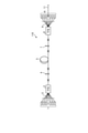
- FIG. 1 is an exemplary schematic configuration diagram of the laser cutting apparatus of the first embodiment.
- FIG. 2 is an exemplary schematic configuration diagram of a laser device included in the laser cutting device of the first embodiment.
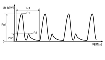
- FIG. 3 is a timing chart showing an example of a change over time in the output of the laser beam emitted from the laser cutting apparatus of the first embodiment.
- FIG. 4 is an enlarged view showing one pulse of the laser beam of FIG.
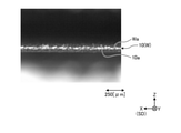
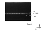
- FIG. 5 is an image taken in a plan view of an example of a cut edge of a metal leaf having a thickness of 100 [ ⁇ m] as a processing target cut by the laser cutting device of the embodiment and its vicinity.
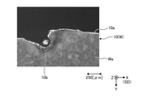
- FIG. 6 is a side view image of the cut edge of the metal foil of FIG. As a reference example, FIG.
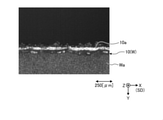
- FIG. 7 is an image taken in a plan view of an example of a cut edge and its vicinity when the same metal leaf as in FIGS. 5 and 6 is laser-cut under conditions different from those in FIGS. 5 and 6.
- FIG. 8 is a side view image of the cut edge of the metal foil of FIG. 7.
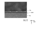
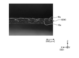
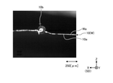
- FIG. 9 is an image taken in a plan view of an example of a cut edge of a metal leaf having a thickness of 10 [ ⁇ m] as a processing target cut by the laser cutting device of the embodiment and its vicinity.
- FIG. 10 is a photographed image of the cut edge of the metal foil of FIG. 9 in a side view.
- FIG. 11 is an image taken in a plan view of an example of a cut edge and its vicinity when the same metal leaf as in FIGS.
- FIG. 9 and 10 is laser-cut under conditions different from those in FIGS. 9 and 10.
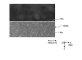
- FIG. 12 is a photographed image of the cut edge of the metal foil of FIG. 11 in a side view.
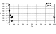
- FIG. 13 is a graph showing the experimental results of laser cutting according to the duty ratio and the index for a plurality of metal leaf samples.
- FIG. 14 is an exemplary schematic configuration diagram of the laser cutting device of the second embodiment.
- the X direction is represented by an arrow X
- the Y direction is represented by an arrow Y
- the Z direction is represented by an arrow Z.
- the X, Y, and Z directions intersect and are orthogonal to each other.
- the Z direction is the normal direction of the surface Wa (processed surface) of the processing target W.
- the X direction is exemplified as the sweep direction SD, but the sweep direction SD may intersect with the Z direction and is not limited to the X direction.
- FIG. 1 is a schematic configuration diagram of the laser cutting device 100 of the first embodiment.
- the laser cutting device 100 includes a laser device 110, an optical head 120, an optical fiber 130 connecting the laser device 110 and the optical head 120, and a controller 140.
- the processing target W of the laser cutting device 100 is made of, for example, a conductive metal material.
- the metal material is, for example, a copper-based material such as copper or a copper alloy, or an aluminum-based material such as aluminum or an aluminum alloy.
- the processing target W may also be referred to as a metal conductor.
- the processing target W is, for example, a metal foil 10 having a thickness of 500 [ ⁇ m] or less, but the processing target W is not limited to this.
- the metal leaf 10 may be an electrode of a battery such as a lithium ion battery.
- the metal leaf 10 may be coated with an active material such as manganese dioxide or lithium.
- the laser cutting device 100 may continuously cut both the portion coated with the active material and the portion not coated with the active material by one sweep.
- the active material may also be referred to as a coating film, a coating film, a coating substance, a surface layer, or a surface layer material.
- the metal leaf 10 as the processing target W of the laser cutting device 100 is not limited to the electrode of the battery, and may be coated with a substance different from the active material, for example, or the plating layer.
- Such a surface layer may be formed, a coating or a surface layer may be formed over the entire surface, or a portion where the coating or the surface layer is formed and a portion where the coating or the surface layer is not formed. It may have and may have no coating or surface layer.
- the laser device 110 is provided with a laser oscillator, and as an example, it is configured to be able to output a single mode laser beam having a power of several kW.
- the laser device 110 will be described later.
- the optical fiber 130 guides the laser light output from the laser device 110 to the optical head 120.
- the optical fiber 130 is configured to propagate the single-mode laser beam.
- M 2 beam quality of the single-mode laser light is set to 1.2 or less.
- the optical fiber 130 is configured to propagate the multimode laser beam.
- the optical head 120 is an optical device for irradiating the processing target W with the laser beam input from the laser device 110.
- the optical head 120 includes a collimating lens 121 and a condenser lens 122.
- the collimating lens 121 and the condenser lens 122 may also be referred to as optical components.
- the optical head 120 may have optical components other than the collimating lens 121 and the condenser lens 122.
- the optical head 120 is configured to be able to change the relative position with the processing target W because the laser light L is swept while irradiating the processing target W with the laser light L.
- the relative movement between the optical head 120 and the processing target W can be realized by the movement of the optical head 120, the movement of the processing target W, or the movement of both the optical head 120 and the processing target W.
- the collimating lens 121 collimates the input laser beam.
- the collimated laser beam becomes parallel light.
- the condenser lens 122 concentrates the laser light as parallel light and irradiates the processing target W as the laser light L (output light).
- the optical head 120 irradiates the surface Wa of the processing target W with the laser beam L in the direction opposite to the Z direction.
- the irradiation direction of the laser beam L from the optical head 120 is opposite to the Z direction.
- the optical head 120 can collect the laser beam L so that the beam diameter is, for example, 10 [ ⁇ m] or more.
- the controller 140 controls the operation of the laser device 110 and the operation of the optical head 120 or the drive mechanism of the stage that supports the processing target W.
- FIG. 2 is a schematic configuration diagram of an example of the laser device 110.
- the laser device 110 may also be referred to as a light source device.
- the laser device 110 in FIG. 2 is a CW laser capable of continuously outputting laser light.
- the laser device 110 may also be referred to as a laser oscillator.
- the laser device 110 exemplified in FIG. 2 is an optical fiber laser, which includes a plurality of semiconductor excitation light sources 1, a plurality of optical fibers 2, an optical combiner 3, an optical fiber plug grating (FBG) 4, and amplification. It includes an optical fiber 5, an FBG 7, an optical combiner 8, a plurality of optical fibers 9, a plurality of semiconductor excitation light sources 6, and an output optical fiber 11. Each element is appropriately connected by an optical fiber.
- the output optical fiber 11 is optically coupled to the optical fiber 130 shown in FIG. 1 or is a part (input end) of the optical fiber 130.
- Each of the plurality of semiconductor excitation light sources 1 as an excitation light source outputs the excitation light supplied to the amplification optical fiber 5.
- the excitation light has a wavelength capable of photoexciting the amplification optical fiber 5, for example, a wavelength of 915 [nm].
- Each of the plurality of optical fibers 2 propagates the excitation light output from each semiconductor excitation light source 1 and outputs the excitation light to the optical combiner 3.
- the optical combiner 3 is composed of TFB (tapered fiber bundle) in this embodiment.
- the optical combiner 3 combines the excitation light input from each optical fiber 2 with the optical fiber of the signal optical port and outputs the excitation light to the amplification optical fiber 5.
- the amplification optical fiber 5 is a YDF (ytterbium doped fiber) in which ytterbium (Yb) ion, which is an amplifying substance, is added to a core portion made of quartz glass, and the outer periphery of the core portion is made of quartz glass. It is a double clad type optical fiber in which the inner clad layer formed and the outer clad layer made of resin or the like are sequentially formed.
- the core portion of the amplification optical fiber 5 has an NA of, for example, 0.08, and is configured to propagate Yb ion emission, for example, light having a wavelength of 1070 [nm] in a single mode.
- the absorption coefficient of the core portion of the amplification optical fiber 5 is, for example, 200 [dB / m] at a wavelength of 915 [nm]. Further, the power conversion efficiency from the excitation light input to the core portion to the laser oscillation light is, for example, 70%.
- the FBG 4 which is the rear end side reflecting means is connected between the optical fiber of the signal optical port of the optical combiner 3 and the optical fiber 5 for amplification.
- the FBG4 has a center wavelength of, for example, 1070 [nm], a reflectance in a wavelength band having a width of about 2 [nm] in and around the center wavelength of about 100%, and almost all light having a wavelength of 915 [nm] is transmitted. do.
- the FBG 7 which is an output side reflecting means is connected between the optical fiber of the signal optical port of the optical combiner 8 and the optical fiber 5 for amplification.
- the FBG7 has a center wavelength of, for example, 1070 [nm], which is substantially the same as that of the FBG4, has a reflectance of about 10% to 30% at the center wavelength, and has a full width at half maximum of the reflection wavelength band of about 1 [nm]. Most of the light having a wavelength of 915 [nm] is transmitted.
- the FBGs 4 and 7 are arranged for each of both ends of the optical fiber 5 for amplification, and form an optical fiber resonator for light having a wavelength of 1070 [nm].
- Each of the plurality of semiconductor excitation light sources 6 as the excitation light source outputs the excitation light supplied to the amplification optical fiber 5.
- the excitation light has a wavelength capable of photoexciting the amplification optical fiber 5, for example, a wavelength of 915 [nm].
- Each of the plurality of optical fibers 9 propagates the excitation light output from each semiconductor excitation light source 6 and outputs the excitation light to the optical combiner 8.
- the optical combiner 8 is composed of a TFB in this embodiment.
- the optical combiner 8 combines the excitation light input from each optical fiber 9 with the optical fiber of the signal optical port and outputs the excitation light to the amplification optical fiber 5.
- Yb ions in the core portion are photoexcited by the excitation light, and light in a band including a wavelength of 1070 [nm] is emitted.
- the light emission having a wavelength of 1070 [nm] is laser-oscillated by the optical amplification action of the amplification optical fiber 5 and the action of the optical resonator composed of the FBGs 4 and 7.
- the output optical fiber 11 is arranged on the opposite side of the FBG 7 and is connected to the optical fiber of the signal optical port of the optical combiner 8.
- the oscillated laser light (laser oscillated light) is output from the output optical fiber 11.
- the laser device 110 operates as a pulse laser that outputs a pulse of laser light under the control of a controller 140 as described later.
- the laser device 110 may be a pulse laser that generates a pulse by another method or a laser device having an optical amplification method different from that of an optical fiber laser.
- the processing target W is set so as to be irradiated with the laser beam L. Then, in a state where the laser beam L is irradiated on the processing target W, the laser light L and the processing target W move relatively. As a result, the laser beam L moves (sweeps) in the sweep direction SD on the surface Wa while being irradiated on the surface Wa. The portion irradiated with the laser beam L is melted and cut.
- FIG. 3 is a timing chart showing a change over time in the power of the laser beam L
- FIG. 4 is an enlarged view of a part (1 pulse) of FIG.
- the pulse frequency of the laser beam L (1 / A, A: pulse period [s], see FIGS. 3 and 4) is 6 [KHz] or more and 1 [MHz] or less. It was found that is suitable.
- the controller 140 controls the laser device 110 so that it is switched on and off, that is, between an output state (operating state) and a stopped state (non-output state, non-operating state) at a high frequency as described above.
- the controller 140 outputs a control signal so that power having a rectangular wave shape is supplied to the semiconductor excitation light sources 1 and 6 in time.
- the change with time of the output of the laser beam L by the laser device 110 does not become a perfect rectangular wave, but becomes a blunt waveform as shown in FIGS. 3 and 4 as an example.
- the inventors have defined the duty ratio Rd [%] of the pulse of the laser beam L output from the laser apparatus 110 as the following equation (1).
- Rd A ⁇ B ⁇ 100 ⁇ ⁇ ⁇ (1)
- B [s] (see FIG. 4) is the full width of the half value of the pulse, and is the width (time width) of the half value (0.5 Pmax) with respect to the maximum value Pmax [W] of the pulse. If there are a plurality of times with 0.5 Pmax in one pulse, the time width is set to the farthest two hours.
- the duty ratio Rd [%] is preferably 0.1 or more and 80 or less, and more preferably 0.2 or more and 40 or less. did.
- the inventors have found a suitable range for the pulse waveform through experimental research.
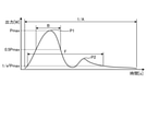
- the inventors defined the pulse ratio Rp as the following equation (2).
- Rp F / B ...
- F is a pulse of 1 / e 2 width
- B is the full width at half maximum of the pulse.
- the 1 / e 2 width of a pulse is a width of a value that is 1 / e 2 ( ⁇ 0.135) with respect to the maximum value Pmax of the pulse, and there are a plurality of values that are 1 / e 2 in one pulse. In some cases, it is the time width between the two farthest hours.
- the pulse ratio Rp is an index showing the spread of the pulse, and the larger the value, the wider the pulse.
- the pulse ratio Rp is preferably 1 or more and 7 or less. Further, it was found that it is preferable that the M2 beam quality of the laser beam L is 1.2 or less and the energy irradiated by the pulse is 0.1 [mJ] or more.
- the inventors have found a suitable range for the index I represented by the following formula (3) by experimental research.
- I A x B x C x D x E ... (3)
- C [m / s] is the sweep speed of the laser beam L
- D [m] is the spot diameter on the surface Wa of the processing target W of the laser beam L
- E [W] is the output of the laser beam L.
- the spot diameter D (beam diameter) includes a peak of the power in the spot is defined as the diameter of the region of 1 / e 2 or more of the power of the peak power.
- the length of the region to be the 1 / e 2 or more of the power of the peak power can be defined as a spot diameter.
- the power distribution in the spot is not limited to the Gaussian shape. Experimental studies by the inventors have found that the index I is preferably 1.0 ⁇ 10 -7 or more and 1.0 ⁇ 10 -1 or less.
- the metal foil 10 as the processing target W is an aluminum foil having a thickness of 100 [ ⁇ m] as an electrode coated with an active material on the surface, and the duty ratio Rd is 6.1. It is an experimental result when the index I is 3.84 ⁇ 10 -3.
- FIG. 5 is a plan view showing the cutting edge 10a and its vicinity
- FIG. 6 is a side view of the cutting edge 10a. As is clear from FIGS. 5 and 6, under this condition, a good cutting edge 10a (processed state) with little or no bending, turning, dross, spatter, etc. is obtained.
- FIGS. 7 and 8 are experimental results as a reference example when the irradiation conditions of the laser beam L are changed for the same processing target W as in FIGS. 5 and 6.
- the duty ratio Rd is 100 and the index I is 3.84 ⁇ 10 -3 .
- the duty ratio Rd of 100 means continuous irradiation of the laser beam L, not intermittent irradiation of the pulsed laser beam L.
- FIG. 7 is a plan view showing the cutting edge 10a and its vicinity
- FIG. 8 is a side view of the cutting edge 10a. As will be clear by comparing FIGS. 7 and 8 with FIGS. 5 and 6, under this condition, the deformation of the cut edge 10a is larger, and the cut edge 10a is turned over or bent.
- FIGS. 9 and 10 the metal leaf 10 as the processing target W is a copper foil having a thickness of 10 [ ⁇ m], the duty ratio Rd is 6.1, and the index I is 3.84 ⁇ 10 -3 . It is an experimental result of the case.
- FIG. 9 is a plan view showing the cutting edge 10a and its vicinity
- FIG. 10 is a side view of the cutting edge 10a. As is clear from FIGS. 9 and 10, under this condition, a good cutting edge 10a (processed state) with little or no bending, turning, dross, spatter, etc. is obtained.
- FIGS. 11 and 12 are experimental results as a reference example when the irradiation conditions of the laser beam L are changed for the same processing target W as in FIGS. 9 and 10.
- the duty ratio Rd is 100 and the index I is 6.3 ⁇ 10-2 . Since the duty ratio Rd is 100, the laser beam L is continuously irradiated even in this case as well.
- FIG. 11 is a plan view showing the cutting edge 10a and its vicinity
- FIG. 12 is a side view of the cutting edge 10a. As is clear from FIGS. 11 and 12, under this condition, dross 10b is generated, and the cutting edge 10a is greatly turned up or bent.
- one metal foil 10 such as an aluminum foil or a copper foil may have a coated portion covered with a film such as an active material and an exposed portion not covered with the film. ..
- the duty ratio Rd and the index I are appropriately set according to the specifications such as the material and thickness of the metal leaf 10 and the coating film.
- a good processing state can be obtained in both the covered part and the exposed part. confirmed.
- laser cutting of the metal leaf 10 having a covered portion and an exposed portion can be performed more quickly, and by extension, a requirement for manufacturing a part or a product containing the metal foil 10. The time can be shortened.
- Sweep speed may change. Changes in sweep speed may adversely affect processing quality.
- the inventors have found that even when the sweep rate changes in continuous laser cutting, for example, the duty ratio Rd and the index I according to the sweep rate are appropriately set or changed. It was confirmed that the processed state could be obtained. According to such a method, it is possible to suppress the deterioration of the processing quality due to the change of the sweep speed, to easily secure the required processing quality, and to increase the processing yield.
- FIG. 13 is a graph showing a part of the experimental results when the horizontal axis is the duty ratio Rd and the vertical axis is the index I. From FIG. 13, it can be seen that suitable laser cutting can be performed when the duty ratio Rd and the index I are each within the predetermined ranges.
- the spot diameter (beam diameter) D is preferably 100 [ ⁇ m] or less, more preferably 50 [ ⁇ m] or less, and 30 [ ⁇ m] or less. Was found to be even more preferable. This is because if the spot diameter D is too large, heat energy is applied to the outside of the cutting region (calf), that is, the processing target W, and there is a possibility that quality defects such as oxidation due to heat may occur.
- the pulse when the pulse has a first peak P1 and a second peak P2 after the first peak P1, the first of the outputs Pp2 of the second peak P2.
- the energy required for cutting may be generated by a pulse having only one peak. May be difficult to give.
- the thermal influence on the periphery of the cutting region may become too large.
- the output ratio Ro is 0.1 or more and 0.5 or less, even for a material having a relatively high reflectance to laser light, the material is first melted by the first peak P1.
- the second peak P2 which has a lower output than the first peak P1, can secure an appropriate amount of energy required for cutting. As a result, more reliable cutting is possible, and the thermal influence on the periphery of the cutting region can be suppressed, and a good cutting edge 10a with little or no bending, turning, dross, spatter, etc. can be obtained. be able to.
- the region is irradiated with the second peak P2 having a lower output than the first peak P1 before the region melted by the first peak P1 is solidified.
- the time interval between the first peak P1 and the second peak P2 can be, for example, 5.0 [ ⁇ sec] or less.
- the machining target W is cut by executing the sweep under the condition that the cutting of the machining target W is not completed by one sweep multiple times in the same route.
- a brittle and fragile material such as ceramic or polymer, an active material or the like (hereinafter referred to as a coating substance) is coated on the surface of the processing target W, if excessive energy is applied, the coating is applied.
- the coating is applied.
- adverse effects such as cracking and evaporation on the material.
- the coated material is cracked or evaporated due to the input of excessive energy. It is possible to suppress the occurrence of such adverse effects.
- the index I is 1.0 ⁇ 10 ⁇ 2 or more and 1.0 ⁇ 10 ⁇ 5 or less. It was found that the processing target W can be cut while suppressing the adverse effect on the coated material by executing the sweep twice.
- the coating substance is removed by irradiation with a laser beam in the cutting region (planned cutting region) and its vicinity, and then the processing target W is cut by executing the sweeping of the laser light of the present embodiment described above. ..
- the laser beam may be swept by the same path in the step of removing the coating substance and the step of performing laser cutting. Further, the laser beam irradiated in the step of removing the coating substance may be a pulse or a continuous wave.
- the processing is performed by intermittently irradiating the surface Wa of the metal leaf 10 as the processing target W with a pulse of laser light L at a frequency of 1 [MHz] or less. Laser cutting the target W.
- the duty ratio Rd [%] of the pulse of the laser beam L may be 0.1 or more and 80 or less, or 0.2 or more and 40 or less.
- the pulse ratio Rp is 1 or more and 7 or less
- the M2 beam quality of the laser beam L is 1.2 or less
- the energy irradiated by the pulse is 0.1 [mJ. ] It may be more than that.
- the index I may be 1.0 ⁇ 10 -7 or more and 1.0 ⁇ 10 -1 or less.
- FIG. 14 is a schematic configuration diagram of the laser cutting device 100A of the second embodiment.
- the optical head 120 has a galvano scanner 126 between the collimating lens 121 and the condenser lens 122.
- the galvano scanner 126 has two mirrors 126a.
- the irradiation direction and irradiation position of the laser beam L change due to the change in the postures of these two mirrors 126a. That is, the laser cutting device 100A can move the irradiation position of the laser beam L and sweep the laser beam L without moving the optical head 120.
- the controller 140 can control the operation of the motor 126b corresponding to each mirror 126a so that the angle (posture) of the mirror 126a changes. The same operation and effect as those of the first embodiment can be obtained by this embodiment as well.
- the surface area of the molten pool may be adjusted by sweeping by known wobbling, weaving, output modulation, or the like.
- the processing target may be one in which another thin metal layer exists on the surface of the metal, such as a plated metal plate.
- the laser device is not limited to the CW laser, and may be, for example, a pulse laser capable of realizing intermittent irradiation at a predetermined high frequency and a duty ratio in a predetermined range.
- the present invention can be used as a laser cutting method for metal foil.
- Sweep speed D ... Spot diameter E ... Output F ... 1 / e 2 width I ... index L ... laser light
- P1 first peak
- P2 second peak
- Pp1, Pp2 ... output
- Pmax maximum value SD
- sweep direction Rd ; duty ratio
- Rp pulse ratio W ... machining target Wa ... Surface X ... Direction Y ... Direction Z ... Direction (normal direction)
Abstract
In this method for cutting a metal foil with a laser, for example, a workpiece, which is a metal foil, is laser cut by intermittently irradiating the surface of the workpiece with pulsed laser light at a frequency of 1 MHz or less. Furthermore, for example, when the frequency is A [Hz] and the full width at half maximum of the pulse is B [s], the duty ratio Rd [%], which is expressed as Rd = A × B × 100, may be 0.1-80. Furthermore, when the full width at half maximum is B and the 1/e2 width of the pulse is F [s], the pulse ratio Rp, which is expressed as Rp = F/B, may be 1-7, the M2 beam quality of the laser light may be 1.2 or less, and the energy radiated by the pulse may be 0.1 [mJ] or greater.
Description
本発明は、金属箔のレーザ切断方法に関する。
The present invention relates to a method for cutting a metal foil by laser.
金属材料で作られた加工対象を切断する手法の一つとして、レーザ光の照射によるレーザ切断が知られている。レーザ切断とは、レーザ光を加工対象の切断する部分に照射し、レーザ光のエネルギで当該部分を溶融させ、加工対象を切断する方法である(例えば、非特許文献1参照)。
Laser cutting by irradiation with laser light is known as one of the methods for cutting a processing target made of a metal material. Laser cutting is a method of irradiating a portion to be cut with a laser beam and melting the portion with the energy of the laser beam to cut the portion to be processed (see, for example, Non-Patent Document 1).
加工対象が金属箔である場合、当該金属箔は変形したり破れたりしやすいため、レーザ切断における各種パラメータを、より厚い金属部材の場合と同様に設定すると、所要の品質が得られ難い場合があった。
When the object to be processed is a metal leaf, the metal leaf is easily deformed or torn. Therefore, if various parameters for laser cutting are set in the same manner as for a thicker metal member, it may be difficult to obtain the required quality. there were.
また、金属箔が例えば電池の電極に適用されるような場合にあっては、ドロスやスパッタの少ないより高品質なレーザ切断が求められる。
Further, when a metal foil is applied to a battery electrode, for example, higher quality laser cutting with less dross and spatter is required.
そこで、本発明の課題の一つは、例えば、加工対象としての金属箔をレーザ切断することが可能な、より改善された新規な金属箔のレーザ切断方法を得ること、である。
Therefore, one of the problems of the present invention is, for example, to obtain a new and improved laser cutting method for a metal foil capable of laser cutting a metal foil to be processed.
本発明の金属箔のレーザ切断方法は、例えば、加工対象としての金属箔の表面にレーザ光のパルスを1[MHz]以下の周波数で断続的に照射することにより当該加工対象をレーザ切断する。
In the laser cutting method of the metal foil of the present invention, for example, the surface of the metal foil to be processed is laser-cut by intermittently irradiating the surface of the metal foil with a pulse of laser light at a frequency of 1 [MHz] or less.
前記金属箔のレーザ切断方法では、前記周波数がA[Hz]であり、かつ前記パルスの半値全幅がB[s]である場合に、次の式
Rd=A×B×100 ・・・(1)
で表されるデューティ比Rd[%]が、0.1以上かつ80以下であってもよい。 In the laser cutting method of the metal foil, when the frequency is A [Hz] and the full width at half maximum of the pulse is B [s], the following equation Rd = A × B × 100 ... (1). )
The duty ratio Rd [%] represented by may be 0.1 or more and 80 or less.
前記金属箔のレーザ切断方法では、前記デューティ比Rd[%]が、0.2以上かつ40以下であってもよい。
In the laser cutting method of the metal foil, the duty ratio Rd [%] may be 0.2 or more and 40 or less.
前記金属箔のレーザ切断方法では、前記半値全幅がBであり前記パルスの1/e2幅がF[s]である場合に次の式
Rp=F/B ・・・(2)
で表されるパルス比Rpが1以上かつ7以下であり、前記レーザ光のM2ビーム品質が1.2以下であり、かつ前記パルスによって照射されるエネルギが0.1[mJ]以上であってもよい。 Wherein in the laser cutting process of the metal foil, the full width at half maximum B at is 1 / e 2 width of the pulse F follows in the case of [s] wherein Rp = F / B ··· (2 )
The pulse ratio Rp represented by is 1 or more and 7 or less, the M2 beam quality of the laser beam is 1.2 or less, and the energy irradiated by the pulse is 0.1 [mJ] or more. May be good.
前記金属箔のレーザ切断方法では、前記レーザ光は、前記表面に対して相対的に掃引され、前記レーザ光の掃引速度がC[m/s]であり、前記表面上での前記レーザ光のスポット径がD[m]であり、かつ前記レーザ光の出力がE[W]である場合に、次の式
I=A×B×C×D×E ・・・(3)
で表される指標Iが、1.0×10⁻⁷以上かつ1.0×10⁻¹以下であってもよい。 In the laser cutting method of the metal foil, the laser beam is swept relative to the surface, the sweep rate of the laser beam is C [m / s], and the laser beam on the surface. When the spot diameter is D [m] and the output of the laser beam is E [W], the following formula I = A × B × C × D × E ... (3)
The index I represented by may be 1.0 × 10 -7 or more and 1.0 × 10 -1 or less.
前記金属箔のレーザ切断方法では、前記加工対象の厚さは、500[μm]以下であってもよい。
In the laser cutting method of the metal foil, the thickness of the processing target may be 500 [μm] or less.
前記金属箔のレーザ切断方法では、前記金属箔は、被膜で覆われた被覆部位と、当該被膜で覆われない露出部位と、を有し、前記レーザ光の掃引により前記被覆部位と前記露出部位とを連続的にレーザ切断してもよい。
In the laser cutting method of the metal foil, the metal foil has a coated portion covered with a coating film and an exposed portion not covered with the coating film, and the coated portion and the exposed portion are swept by the laser beam. And may be continuously laser cut.
前記金属箔のレーザ切断方法では、前記レーザ光の前記表面上でのスポット径は、100[μm]以下であってもよい。
In the laser cutting method of the metal foil, the spot diameter of the laser beam on the surface may be 100 [μm] or less.
前記金属箔のレーザ切断方法では、前記スポット径は、50[μm]以下であってもよい。
In the laser cutting method of the metal foil, the spot diameter may be 50 [μm] or less.
前記金属箔のレーザ切断方法では、前記パルスは、第一ピークと、当該第一ピークよりも後の第二ピークと、を有し、前記第二ピークの出力Pp2の前記第一ピークの出力Pp1に対する比である出力比Ro(=Pp2/Pp1)は、0.1以上かつ0.5以下であってもよい。
In the method of laser cutting of a metal foil, the pulse has a first peak and a second peak after the first peak, and the output Pp2 of the first peak is the output Pp1 of the second peak. The output ratio Ro (= Pp2 / Pp1), which is a ratio to, may be 0.1 or more and 0.5 or less.
前記金属箔のレーザ切断方法では、前記表面に対する前記レーザ光の掃引を複数回実行することにより前記加工対象をレーザ切断してもよい。
In the laser cutting method of the metal foil, the processing target may be laser-cut by performing the sweeping of the laser light on the surface a plurality of times.
前記金属箔のレーザ切断方法では、前記複数回の前記レーザ光の掃引における各回の掃引を、1回の掃引では前記加工対象を切断できない条件で実行してもよい。
In the laser cutting method of the metal foil, each sweep in the plurality of sweeps of the laser beam may be executed under the condition that the processing target cannot be cut by one sweep.
前記金属箔のレーザ切断方法では、前記レーザ光の掃引速度がC[m/s]であり、前記表面上での前記レーザ光のスポット径がD[m]であり、かつ前記レーザ光の出力がE[W]である場合に、次の式
I=A×B×C×D×E ・・・(3)
で表される指標Iが、1.0×10⁻²以上かつ1.0×10⁻⁵以下である条件で、前記レーザ光の掃引を2回実行することにより、厚さが100[μm]以上である前記加工対象をレーザ切断してもよい。 In the laser cutting method of the metal foil, the sweep speed of the laser beam is C [m / s], the spot diameter of the laser beam on the surface is D [m], and the output of the laser beam. When is E [W], the following equation I = A × B × C × D × E ... (3)
By executing the sweeping of the laser beam twice under the condition that the index I represented by is 1.0 × 10 −2 or more and 1.0 × 10 −5 or less, the thickness is 100 [μm]. The above-mentioned processing target may be laser-cut.
前記金属箔のレーザ切断方法では、前記加工対象をレーザ切断する工程の前に、レーザ光の照射により前記表面上の塗布物質を除去する工程を有してもよい。
The laser cutting method for the metal foil may include a step of removing the coating substance on the surface by irradiating the surface with a laser beam before the step of laser cutting the processing target.
前記金属箔のレーザ切断方法では、前記表面上の塗布物質を除去する工程、および前記加工対象をレーザ切断する工程において、前記表面上の同じ経路で前記レーザ光を掃引してもよい。
In the laser cutting method of the metal foil, the laser light may be swept by the same path on the surface in the step of removing the coating substance on the surface and the step of laser cutting the processing target.
本発明によれば、加工対象としての金属箔をレーザ切断することが可能な、より改善された新規な金属箔のレーザ切断方法を得ることができる。
According to the present invention, it is possible to obtain a new and improved laser cutting method for a metal foil, which is capable of laser cutting a metal foil to be processed.
以下、本発明の例示的な実施形態が開示される。以下に示される実施形態の構成、ならびに当該構成によってもたらされる作用および結果(効果)は、一例である。本発明は、以下の実施形態に開示される構成以外によっても実現可能である。また、本発明によれば、構成によって得られる種々の効果(派生的な効果も含む)のうち少なくとも一つを得ることが可能である。
Hereinafter, exemplary embodiments of the present invention will be disclosed. The configurations of the embodiments shown below, as well as the actions and results (effects) brought about by the configurations, are examples. The present invention can also be realized by configurations other than those disclosed in the following embodiments. Further, according to the present invention, it is possible to obtain at least one of various effects (including derivative effects) obtained by the configuration.
以下に示される実施形態は、同様の構成を備えている。よって、各実施形態の構成によれば、当該同様の構成に基づく同様の作用および効果が得られる。また、以下では、それら同様の構成には同様の符号が付与されるとともに、重複する説明が省略される場合がある。
The embodiments shown below have a similar configuration. Therefore, according to the configuration of each embodiment, the same operation and effect based on the similar configuration can be obtained. Further, in the following, the same reference numerals are given to those similar configurations, and duplicate explanations may be omitted.
また、各図において、X方向を矢印Xで表し、Y方向を矢印Yで表し、Z方向を矢印Zで表している。X方向、Y方向、およびZ方向は、互いに交差するとともに直交している。Z方向は、加工対象Wの表面Wa(加工面)の法線方向である。なお、いくつかの図中では、X方向が掃引方向SDとして例示されているが、掃引方向SDは、Z方向と交差していればよく、X方向には限定されない。
Further, in each figure, the X direction is represented by an arrow X, the Y direction is represented by an arrow Y, and the Z direction is represented by an arrow Z. The X, Y, and Z directions intersect and are orthogonal to each other. The Z direction is the normal direction of the surface Wa (processed surface) of the processing target W. In some figures, the X direction is exemplified as the sweep direction SD, but the sweep direction SD may intersect with the Z direction and is not limited to the X direction.
[第1実施形態]
[レーザ切断装置の構成]
図1は、第1実施形態のレーザ切断装置100の概略構成図である。レーザ切断装置100は、レーザ装置110と、光学ヘッド120と、レーザ装置110と光学ヘッド120とを接続する光ファイバ130と、コントローラ140と、を備えている。 [First Embodiment]
[Laser cutting device configuration]
FIG. 1 is a schematic configuration diagram of thelaser cutting device 100 of the first embodiment. The laser cutting device 100 includes a laser device 110, an optical head 120, an optical fiber 130 connecting the laser device 110 and the optical head 120, and a controller 140.
[レーザ切断装置の構成]
図1は、第1実施形態のレーザ切断装置100の概略構成図である。レーザ切断装置100は、レーザ装置110と、光学ヘッド120と、レーザ装置110と光学ヘッド120とを接続する光ファイバ130と、コントローラ140と、を備えている。 [First Embodiment]
[Laser cutting device configuration]
FIG. 1 is a schematic configuration diagram of the
レーザ切断装置100の加工対象Wは、例えば、導電性を有した金属材料で作られている。金属材料は、例えば、銅や銅合金のような銅系材料や、アルミニウムやアルミニウム合金のようなアルミニウム系材料である。このような場合、加工対象Wは、金属導体とも称されうる。
The processing target W of the laser cutting device 100 is made of, for example, a conductive metal material. The metal material is, for example, a copper-based material such as copper or a copper alloy, or an aluminum-based material such as aluminum or an aluminum alloy. In such a case, the processing target W may also be referred to as a metal conductor.
また、加工対象Wは、例えば、厚さが500[μm]以下の金属箔10であるが、これには限定されない。
Further, the processing target W is, for example, a metal foil 10 having a thickness of 500 [μm] or less, but the processing target W is not limited to this.
また、金属箔10は、例えば、リチウムイオン電池のような電池の、電極であってもよい。この場合、金属箔10には、例えば、二酸化マンガンやリチウムのような活物質が塗布されていてもよい。また、レーザ切断装置100は、活物質が塗布された部分、および活物質が塗布されていない部分の双方を、1度の掃引で連続的に切断してもよい。活物質は、被膜や、塗膜、塗布物質、表層、表層材とも称されうる。なお、レーザ切断装置100の加工対象Wとしての金属箔10は、電池の電極には限定されず、例えば、活物質以外とは異なる物質が塗布されたものであってもよいし、めっき層のような表層が形成されたものであってもよいし、表面の全体に渡って被膜や表層が形成されたものであってもよいし、被膜や表層が形成された部分と形成されていない部分とを有してもよいし、被膜や表層が無くてもよい。
Further, the metal leaf 10 may be an electrode of a battery such as a lithium ion battery. In this case, the metal leaf 10 may be coated with an active material such as manganese dioxide or lithium. Further, the laser cutting device 100 may continuously cut both the portion coated with the active material and the portion not coated with the active material by one sweep. The active material may also be referred to as a coating film, a coating film, a coating substance, a surface layer, or a surface layer material. The metal leaf 10 as the processing target W of the laser cutting device 100 is not limited to the electrode of the battery, and may be coated with a substance different from the active material, for example, or the plating layer. Such a surface layer may be formed, a coating or a surface layer may be formed over the entire surface, or a portion where the coating or the surface layer is formed and a portion where the coating or the surface layer is not formed. It may have and may have no coating or surface layer.
レーザ装置110は、レーザ発振器を備えており、一例としては、数kWのパワーのシングルモードのレーザ光を出力できるよう構成されている。レーザ装置110については後述する。
The laser device 110 is provided with a laser oscillator, and as an example, it is configured to be able to output a single mode laser beam having a power of several kW. The laser device 110 will be described later.
光ファイバ130は、レーザ装置110から出力されたレーザ光を光学ヘッド120に導く。レーザ装置110が、シングルモードレーザ光を出力する場合、光ファイバ130は、シングルモードレーザ光を伝播するよう構成される。この場合、シングルモードレーザ光のM2ビーム品質は、1.2以下に設定される。また、レーザ装置110が、マルチモードレーザ光を出力する場合、光ファイバ130はマルチモードレーザ光を伝播するよう、構成される。
The optical fiber 130 guides the laser light output from the laser device 110 to the optical head 120. When the laser device 110 outputs a single-mode laser beam, the optical fiber 130 is configured to propagate the single-mode laser beam. In this case, M 2 beam quality of the single-mode laser light is set to 1.2 or less. Further, when the laser device 110 outputs the multimode laser beam, the optical fiber 130 is configured to propagate the multimode laser beam.
光学ヘッド120は、レーザ装置110から入力されたレーザ光を、加工対象Wへ照射するための光学装置である。光学ヘッド120は、コリメートレンズ121と、集光レンズ122と、を有している。コリメートレンズ121および集光レンズ122は、光学部品とも称されうる。光学ヘッド120は、コリメートレンズ121および集光レンズ122以外の光学部品を有してもよい。
The optical head 120 is an optical device for irradiating the processing target W with the laser beam input from the laser device 110. The optical head 120 includes a collimating lens 121 and a condenser lens 122. The collimating lens 121 and the condenser lens 122 may also be referred to as optical components. The optical head 120 may have optical components other than the collimating lens 121 and the condenser lens 122.
本実施形態では、光学ヘッド120は、加工対象W上でレーザ光Lの照射を行いながらレーザ光Lを掃引するため、加工対象Wとの相対位置を変更可能に構成されている。光学ヘッド120と加工対象Wとの相対移動は、光学ヘッド120の移動、加工対象Wの移動、または光学ヘッド120および加工対象Wの双方の移動により、実現されうる。
In the present embodiment, the optical head 120 is configured to be able to change the relative position with the processing target W because the laser light L is swept while irradiating the processing target W with the laser light L. The relative movement between the optical head 120 and the processing target W can be realized by the movement of the optical head 120, the movement of the processing target W, or the movement of both the optical head 120 and the processing target W.
コリメートレンズ121は、入力されたレーザ光をコリメートする。コリメートされたレーザ光は、平行光になる。また、集光レンズ122は、平行光としてのレーザ光を集光し、レーザ光L(出力光)として、加工対象Wに照射する。
The collimating lens 121 collimates the input laser beam. The collimated laser beam becomes parallel light. Further, the condenser lens 122 concentrates the laser light as parallel light and irradiates the processing target W as the laser light L (output light).
このような構成により、光学ヘッド120は、加工対象Wの表面Waへ、Z方向の反対方向に、レーザ光Lを照射する。光学ヘッド120からのレーザ光Lの照射方向は、Z方向の反対方向である。また、光学ヘッド120は、例えば、ビーム径が10[μm]以上となるようにレーザ光Lを集光することができる。
With such a configuration, the optical head 120 irradiates the surface Wa of the processing target W with the laser beam L in the direction opposite to the Z direction. The irradiation direction of the laser beam L from the optical head 120 is opposite to the Z direction. Further, the optical head 120 can collect the laser beam L so that the beam diameter is, for example, 10 [μm] or more.
コントローラ140は、レーザ装置110の作動や、光学ヘッド120または加工対象Wを支持するステージの駆動機構の作動を制御する。
The controller 140 controls the operation of the laser device 110 and the operation of the optical head 120 or the drive mechanism of the stage that supports the processing target W.
[レーザ装置]
図2は、レーザ装置110の一例の概略構成図である。レーザ装置110は、光源装置とも称されうる。図2のレーザ装置110は、連続的にレーザ光を出力し得るCWレーザである。レーザ装置110は、レーザ発振器とも称されうる。 [Laser device]
FIG. 2 is a schematic configuration diagram of an example of thelaser device 110. The laser device 110 may also be referred to as a light source device. The laser device 110 in FIG. 2 is a CW laser capable of continuously outputting laser light. The laser device 110 may also be referred to as a laser oscillator.
図2は、レーザ装置110の一例の概略構成図である。レーザ装置110は、光源装置とも称されうる。図2のレーザ装置110は、連続的にレーザ光を出力し得るCWレーザである。レーザ装置110は、レーザ発振器とも称されうる。 [Laser device]
FIG. 2 is a schematic configuration diagram of an example of the
図2に例示されるレーザ装置110は、光ファイバレーザであって、複数の半導体励起光源1と、複数の光ファイバ2と、光合波器3と、光ファイバブラッググレーティング(FBG)4と、増幅用光ファイバ5と、FBG7と、光合波器8と、複数の光ファイバ9と、複数の半導体励起光源6と、出力光ファイバ11とを備えている。各要素は適宜光ファイバで接続されている。出力光ファイバ11は、図1に示される光ファイバ130と光学的に結合されるか、あるいは光ファイバ130の一部(入力端)である。
The laser device 110 exemplified in FIG. 2 is an optical fiber laser, which includes a plurality of semiconductor excitation light sources 1, a plurality of optical fibers 2, an optical combiner 3, an optical fiber plug grating (FBG) 4, and amplification. It includes an optical fiber 5, an FBG 7, an optical combiner 8, a plurality of optical fibers 9, a plurality of semiconductor excitation light sources 6, and an output optical fiber 11. Each element is appropriately connected by an optical fiber. The output optical fiber 11 is optically coupled to the optical fiber 130 shown in FIG. 1 or is a part (input end) of the optical fiber 130.
励起光源である複数の半導体励起光源1は、それぞれ、増幅用光ファイバ5に供給する励起光を出力する。励起光は、増幅用光ファイバ5を光励起できる波長、たとえば915[nm]の波長を有している。複数の光ファイバ2は、それぞれ、各半導体励起光源1から出力された励起光を伝搬し、光合波器3に出力する。
Each of the plurality of semiconductor excitation light sources 1 as an excitation light source outputs the excitation light supplied to the amplification optical fiber 5. The excitation light has a wavelength capable of photoexciting the amplification optical fiber 5, for example, a wavelength of 915 [nm]. Each of the plurality of optical fibers 2 propagates the excitation light output from each semiconductor excitation light source 1 and outputs the excitation light to the optical combiner 3.
光合波器3は、本実施形態ではTFB(tapered fiber bundle)で構成されている。光合波器3は、各光ファイバ2から入力された励起光を、信号光ポートの光ファイバに合波し、増幅用光ファイバ5へ出力する。
The optical combiner 3 is composed of TFB (tapered fiber bundle) in this embodiment. The optical combiner 3 combines the excitation light input from each optical fiber 2 with the optical fiber of the signal optical port and outputs the excitation light to the amplification optical fiber 5.
増幅用光ファイバ5は、石英系ガラスで作られたコア部に増幅物質であるイッテルビウム(Yb)イオンが添加されたYDF(ytterbium doped fiber)であり、コア部の外周には石英系ガラスで作られた内側クラッド層と樹脂等で作られた外側クラッド層とが順次形成されたダブルクラッド型の光ファイバである。なお、増幅用光ファイバ5のコア部はNAがたとえば0.08であり、Ybイオンの発光、たとえば波長1070[nm]の光をシングルモードで伝搬するように構成されている。増幅用光ファイバ5のコア部の吸収係数は、たとえば波長915[nm]において200[dB/m]である。また、コア部に入力された励起光からレーザ発振光へのパワー変換効率はたとえば70%である。
The amplification optical fiber 5 is a YDF (ytterbium doped fiber) in which ytterbium (Yb) ion, which is an amplifying substance, is added to a core portion made of quartz glass, and the outer periphery of the core portion is made of quartz glass. It is a double clad type optical fiber in which the inner clad layer formed and the outer clad layer made of resin or the like are sequentially formed. The core portion of the amplification optical fiber 5 has an NA of, for example, 0.08, and is configured to propagate Yb ion emission, for example, light having a wavelength of 1070 [nm] in a single mode. The absorption coefficient of the core portion of the amplification optical fiber 5 is, for example, 200 [dB / m] at a wavelength of 915 [nm]. Further, the power conversion efficiency from the excitation light input to the core portion to the laser oscillation light is, for example, 70%.
後端側反射手段であるFBG4は、光合波器3の信号光ポートの光ファイバと増幅用光ファイバ5との間に接続されている。FBG4は、中心波長が例えば1070[nm]であり、中心波長およびその周辺の約2[nm]の幅の波長帯域における反射率が約100%であり、波長915[nm]の光はほとんど透過する。また、出力側反射手段であるFBG7は、光合波器8の信号光ポートの光ファイバと増幅用光ファイバ5との間に接続されている。FBG7は、中心波長がFBG4と略同じである例えば1070[nm]であり、中心波長における反射率が10%~30%程度であり、反射波長帯域の半値全幅が約1[nm]であり、波長915[nm]の光はほとんど透過する。
The FBG 4 which is the rear end side reflecting means is connected between the optical fiber of the signal optical port of the optical combiner 3 and the optical fiber 5 for amplification. The FBG4 has a center wavelength of, for example, 1070 [nm], a reflectance in a wavelength band having a width of about 2 [nm] in and around the center wavelength of about 100%, and almost all light having a wavelength of 915 [nm] is transmitted. do. Further, the FBG 7 which is an output side reflecting means is connected between the optical fiber of the signal optical port of the optical combiner 8 and the optical fiber 5 for amplification. The FBG7 has a center wavelength of, for example, 1070 [nm], which is substantially the same as that of the FBG4, has a reflectance of about 10% to 30% at the center wavelength, and has a full width at half maximum of the reflection wavelength band of about 1 [nm]. Most of the light having a wavelength of 915 [nm] is transmitted.
FBG4,7は、増幅用光ファイバ5の両端のそれぞれに対して配置され、波長1070[nm]の光に対して光ファイバ共振器を構成する。
The FBGs 4 and 7 are arranged for each of both ends of the optical fiber 5 for amplification, and form an optical fiber resonator for light having a wavelength of 1070 [nm].
励起光源である複数の半導体励起光源6は、それぞれ、増幅用光ファイバ5に供給する励起光を出力する。励起光は、増幅用光ファイバ5を光励起できる波長、たとえば915[nm]の波長を有している。複数の光ファイバ9は、それぞれ、各半導体励起光源6から出力された励起光を伝搬し、光合波器8に出力する。
Each of the plurality of semiconductor excitation light sources 6 as the excitation light source outputs the excitation light supplied to the amplification optical fiber 5. The excitation light has a wavelength capable of photoexciting the amplification optical fiber 5, for example, a wavelength of 915 [nm]. Each of the plurality of optical fibers 9 propagates the excitation light output from each semiconductor excitation light source 6 and outputs the excitation light to the optical combiner 8.
光合波器8は、光合波器3と同様に、本実施形態ではTFBで構成されている。光合波器8は、各光ファイバ9から入力された励起光を信号光ポートの光ファイバに合波し、増幅用光ファイバ5へ出力する。
Like the optical combiner 3, the optical combiner 8 is composed of a TFB in this embodiment. The optical combiner 8 combines the excitation light input from each optical fiber 9 with the optical fiber of the signal optical port and outputs the excitation light to the amplification optical fiber 5.
増幅用光ファイバ5では、励起光によってコア部のYbイオンが光励起され、波長1070[nm]を含む帯域の光を発光する。波長1070[nm]の発光は、増幅用光ファイバ5の光増幅作用とFBG4,7によって構成される光共振器の作用とによってレーザ発振する。
In the amplification optical fiber 5, Yb ions in the core portion are photoexcited by the excitation light, and light in a band including a wavelength of 1070 [nm] is emitted. The light emission having a wavelength of 1070 [nm] is laser-oscillated by the optical amplification action of the amplification optical fiber 5 and the action of the optical resonator composed of the FBGs 4 and 7.
出力光ファイバ11は、FBG7とは反対側に配置され、光合波器8の信号光ポートの光ファイバに接続されている。発振したレーザ光(レーザ発振光)は出力光ファイバ11から出力される。レーザ装置110は、後述するようなコントローラ140の制御によって、レーザ光のパルスを出力するパルスレーザとして作動する。ただし、レーザ装置110 は、他の方式でパルスを発生するパルスレーザや、光ファイバレーザとは異なる光増幅方式のレーザ装置であってもよい。
The output optical fiber 11 is arranged on the opposite side of the FBG 7 and is connected to the optical fiber of the signal optical port of the optical combiner 8. The oscillated laser light (laser oscillated light) is output from the output optical fiber 11. The laser device 110 operates as a pulse laser that outputs a pulse of laser light under the control of a controller 140 as described later. However, the laser device 110 may be a pulse laser that generates a pulse by another method or a laser device having an optical amplification method different from that of an optical fiber laser.
[レーザ切断方法]
レーザ切断装置100を用いたレーザ切断にあっては、まず、加工対象Wが、レーザ光Lが照射されるようにセットされる。そして、レーザ光Lが加工対象Wに照射されている状態で、レーザ光Lと加工対象Wとが相対的に移動する。これにより、レーザ光Lが表面Wa上に照射されながら当該表面Wa上を掃引方向SDに移動する(掃引する)。レーザ光Lが照射された部分は、溶融し、切断される。 [Laser cutting method]
In the laser cutting using thelaser cutting device 100, first, the processing target W is set so as to be irradiated with the laser beam L. Then, in a state where the laser beam L is irradiated on the processing target W, the laser light L and the processing target W move relatively. As a result, the laser beam L moves (sweeps) in the sweep direction SD on the surface Wa while being irradiated on the surface Wa. The portion irradiated with the laser beam L is melted and cut.
レーザ切断装置100を用いたレーザ切断にあっては、まず、加工対象Wが、レーザ光Lが照射されるようにセットされる。そして、レーザ光Lが加工対象Wに照射されている状態で、レーザ光Lと加工対象Wとが相対的に移動する。これにより、レーザ光Lが表面Wa上に照射されながら当該表面Wa上を掃引方向SDに移動する(掃引する)。レーザ光Lが照射された部分は、溶融し、切断される。 [Laser cutting method]
In the laser cutting using the
[間欠照射]
図3は、レーザ光Lのパワーの経時変化を示すタイミングチャートであり、図4は、図3の一部(1パルス)の拡大図である。 [Intermittent irradiation]
FIG. 3 is a timing chart showing a change over time in the power of the laser beam L, and FIG. 4 is an enlarged view of a part (1 pulse) of FIG.
図3は、レーザ光Lのパワーの経時変化を示すタイミングチャートであり、図4は、図3の一部(1パルス)の拡大図である。 [Intermittent irradiation]
FIG. 3 is a timing chart showing a change over time in the power of the laser beam L, and FIG. 4 is an enlarged view of a part (1 pulse) of FIG.
レーザ切断において、金属箔10に強いレーザ光Lが当たると、切断縁が屈曲したりめくれたりすることがある。かと言って、レーザ光Lの出力を小さくすると、レーザ切断に時間を要してしまう。そこで、発明者らは、鋭意研究を重ねた結果、加工対象Wが金属箔10である場合には、図3,4に示されるように、レーザ光Lを表面Waに所定の周波数で間欠的に(断続的に)照射することにより、より短い加工時間でより良好な結果が得られるという知見を得た。
In laser cutting, when a strong laser beam L hits the metal foil 10, the cutting edge may be bent or turned over. However, if the output of the laser beam L is reduced, it takes time to cut the laser. Therefore, as a result of repeated diligent research, the inventors intermittently apply the laser beam L to the surface Wa at a predetermined frequency as shown in FIGS. 3 and 4 when the processing target W is the metal foil 10. It was found that better results can be obtained with shorter processing time by (intermittently) irradiation.
発明者らは、実験的な研究により、レーザ光Lのパルスの周波数(1/A、A:パルス周期[s]、図3,4参照)は、6[KHz]以上かつ1[MHz]以下であるのが好適であることを見出した。
According to experimental research, the inventors have found that the pulse frequency of the laser beam L (1 / A, A: pulse period [s], see FIGS. 3 and 4) is 6 [KHz] or more and 1 [MHz] or less. It was found that is suitable.
また、発明者らは、実験的な研究により、レーザ光Lのパルスのデューティ比Rdについて、好適な範囲を見出した。ここで、コントローラ140は、上述したような高い周波数で、オンとオフ、すなわち出力状態(作動状態)と停止状態(非出力状態、非作動状態)とが切り替わるよう、レーザ装置110を制御する。具体的には、例えば、コントローラ140は、時間的に矩形波形状の電力が半導体励起光源1,6に供給されるよう、制御信号を出力する。この場合、レーザ装置110によるレーザ光Lの出力の経時変化は、完全な矩形波にはならず、一例としては、図3,4に示されるような鈍った波形になる。そこで、発明者らは、レーザ装置110から出力されるレーザ光Lのパルスのデューティ比Rd[%]を、以下の式(1)のように定義した。
Rd=A×B×100 ・・・(1)
ここに、B[s](図4参照)は、パルスの半値全幅であり、パルスの最大値Pmax[W]に対して、その半値(0.5Pmax)となる値の幅(時間幅)であって、1パルス内に0.5Pmaxとなる複数の時刻がある場合には、最も遠い2時刻間の時間幅とする。発明者らの実験的な研究により、デューティ比Rd[%]は、0.1以上80以下であるのが好適であり、0.2以上40以下であるのがより一層好適であることが判明した。 In addition, the inventors have found a suitable range for the duty ratio Rd of the pulse of the laser beam L by experimental research. Here, thecontroller 140 controls the laser device 110 so that it is switched on and off, that is, between an output state (operating state) and a stopped state (non-output state, non-operating state) at a high frequency as described above. Specifically, for example, the controller 140 outputs a control signal so that power having a rectangular wave shape is supplied to the semiconductor excitation light sources 1 and 6 in time. In this case, the change with time of the output of the laser beam L by the laser device 110 does not become a perfect rectangular wave, but becomes a blunt waveform as shown in FIGS. 3 and 4 as an example. Therefore, the inventors have defined the duty ratio Rd [%] of the pulse of the laser beam L output from the laser apparatus 110 as the following equation (1).
Rd = A × B × 100 ・ ・ ・ (1)
Here, B [s] (see FIG. 4) is the full width of the half value of the pulse, and is the width (time width) of the half value (0.5 Pmax) with respect to the maximum value Pmax [W] of the pulse. If there are a plurality of times with 0.5 Pmax in one pulse, the time width is set to the farthest two hours. Experimental studies by the inventors have revealed that the duty ratio Rd [%] is preferably 0.1 or more and 80 or less, and more preferably 0.2 or more and 40 or less. did.
Rd=A×B×100 ・・・(1)
ここに、B[s](図4参照)は、パルスの半値全幅であり、パルスの最大値Pmax[W]に対して、その半値(0.5Pmax)となる値の幅(時間幅)であって、1パルス内に0.5Pmaxとなる複数の時刻がある場合には、最も遠い2時刻間の時間幅とする。発明者らの実験的な研究により、デューティ比Rd[%]は、0.1以上80以下であるのが好適であり、0.2以上40以下であるのがより一層好適であることが判明した。 In addition, the inventors have found a suitable range for the duty ratio Rd of the pulse of the laser beam L by experimental research. Here, the
Rd = A × B × 100 ・ ・ ・ (1)
Here, B [s] (see FIG. 4) is the full width of the half value of the pulse, and is the width (time width) of the half value (0.5 Pmax) with respect to the maximum value Pmax [W] of the pulse. If there are a plurality of times with 0.5 Pmax in one pulse, the time width is set to the farthest two hours. Experimental studies by the inventors have revealed that the duty ratio Rd [%] is preferably 0.1 or more and 80 or less, and more preferably 0.2 or more and 40 or less. did.
また、発明者らは、実験的な研究により、パルスの波形について、好適な範囲を見出した。ここで、発明者らは、パルス比Rpを、以下の式(2)のように定義した。
Rp=F/B ・・・(2)
ここに、Fは、パルスの1/e2幅、Bは、パルスの半値全幅である。パルスの1/e2幅とは、パルスの最大値Pmaxに対して、1/e2(≒0.135)となる値の幅であり、1パルス内に1/e2となる値が複数ある場合には、最も遠い2時刻間の時間幅とする。パルス比Rpは、パルスの広がりを表す指標であり、値が大きいほど、パルスが広がっていることを示す。発明者らの実験的な研究により、パルス比Rpは、1以上かつ7以下であるのが好適であることが判明した。また、レーザ光LのM2ビーム品質が1.2以下であり、かつパルスによって照射されるエネルギが0.1[mJ]以上であるのが好適であることが、判明した。 In addition, the inventors have found a suitable range for the pulse waveform through experimental research. Here, the inventors defined the pulse ratio Rp as the following equation (2).
Rp = F / B ... (2)
Here, F is a pulse of 1 / e 2 width, B is the full width at half maximum of the pulse. The 1 / e 2 width of a pulse is a width of a value that is 1 / e 2 (≈0.135) with respect to the maximum value Pmax of the pulse, and there are a plurality of values that are 1 / e 2 in one pulse. In some cases, it is the time width between the two farthest hours. The pulse ratio Rp is an index showing the spread of the pulse, and the larger the value, the wider the pulse. Experimental studies by the inventors have found that the pulse ratio Rp is preferably 1 or more and 7 or less. Further, it was found that it is preferable that the M2 beam quality of the laser beam L is 1.2 or less and the energy irradiated by the pulse is 0.1 [mJ] or more.
さらに、発明者らは、実験的な研究により、以下の式(3)で示される指標Iについて、好適な範囲を見出した。
I=A×B×C×D×E ・・・(3)
ここに、C[m/s]は、レーザ光Lの掃引速度、D[m]は、レーザ光Lの加工対象Wの表面Wa上におけるスポット径、E[W]は、レーザ光Lの出力である。なお、スポット径D(ビーム径)は、そのスポットにおけるパワーのピークを含み、ピークパワーの1/e2以上のパワーの領域の径として定義する。また、円形でないスポットの場合は、掃引方向SDと垂直方向における、ピークパワーの1/e2以上のパワーとなる領域の長さをスポット径と定義できる。なお、スポットにおけるパワー分布はガウシアン形状には限定されない。発明者らの実験的な研究により、指標Iは、1.0×10-7以上かつ1.0×10-1以下であるのが好適であることが、判明した。 Furthermore, the inventors have found a suitable range for the index I represented by the following formula (3) by experimental research.
I = A x B x C x D x E ... (3)
Here, C [m / s] is the sweep speed of the laser beam L, D [m] is the spot diameter on the surface Wa of the processing target W of the laser beam L, and E [W] is the output of the laser beam L. Is. Incidentally, the spot diameter D (beam diameter) includes a peak of the power in the spot is defined as the diameter of the region of 1 / e 2 or more of the power of the peak power. In the case of the spot is not circular, in the sweep direction SD and the vertical direction, the length of the region to be the 1 / e 2 or more of the power of the peak power can be defined as a spot diameter. The power distribution in the spot is not limited to the Gaussian shape. Experimental studies by the inventors have found that the index I is preferably 1.0 × 10 -7 or more and 1.0 × 10 -1 or less.
[実験結果]
図5,6は、加工対象Wとしての金属箔10が、表面に活物質の塗布された電極としての厚さ100[μm]のアルミニウム箔であり、デューティ比Rdが6.1であり、かつ指標Iが3.84×10⁻³の場合の実験結果である。図5は、切断縁10aおよびその近傍を示す平面図、図6は、切断縁10aの側面図である。図5,6から明らかとなるように、この条件においては、曲がりや、めくれ、ドロス、スパッタ等が少ないかあるいは無い、良好な切断縁10a(加工状態)が得られている。 [Experimental result]
In FIGS. 5 and 6, themetal foil 10 as the processing target W is an aluminum foil having a thickness of 100 [μm] as an electrode coated with an active material on the surface, and the duty ratio Rd is 6.1. It is an experimental result when the index I is 3.84 × 10 -3. FIG. 5 is a plan view showing the cutting edge 10a and its vicinity, and FIG. 6 is a side view of the cutting edge 10a. As is clear from FIGS. 5 and 6, under this condition, a good cutting edge 10a (processed state) with little or no bending, turning, dross, spatter, etc. is obtained.
図5,6は、加工対象Wとしての金属箔10が、表面に活物質の塗布された電極としての厚さ100[μm]のアルミニウム箔であり、デューティ比Rdが6.1であり、かつ指標Iが3.84×10⁻³の場合の実験結果である。図5は、切断縁10aおよびその近傍を示す平面図、図6は、切断縁10aの側面図である。図5,6から明らかとなるように、この条件においては、曲がりや、めくれ、ドロス、スパッタ等が少ないかあるいは無い、良好な切断縁10a(加工状態)が得られている。 [Experimental result]
In FIGS. 5 and 6, the
図7,8は、図5,6と同じ加工対象Wに対して、レーザ光Lの照射条件を変えた場合の参考例としての実験結果である。図7,8では、デューティ比Rdは100であり、かつ指標Iは3.84×10⁻³である。デューティ比Rdが100であることは、パルス状のレーザ光Lの間欠照射ではなく、レーザ光Lの連続照射であることを意味している。図7は、切断縁10aおよびその近傍を示す平面図、図8は、切断縁10aの側面図である。図7,8を図5,6と比較参照すれば明らかとなるように、この条件においては、切断縁10aの変形がより大きく、めくれたり曲がったりしている。
FIGS. 7 and 8 are experimental results as a reference example when the irradiation conditions of the laser beam L are changed for the same processing target W as in FIGS. 5 and 6. In FIGS. 7 and 8, the duty ratio Rd is 100 and the index I is 3.84 × 10 -3 . The duty ratio Rd of 100 means continuous irradiation of the laser beam L, not intermittent irradiation of the pulsed laser beam L. FIG. 7 is a plan view showing the cutting edge 10a and its vicinity, and FIG. 8 is a side view of the cutting edge 10a. As will be clear by comparing FIGS. 7 and 8 with FIGS. 5 and 6, under this condition, the deformation of the cut edge 10a is larger, and the cut edge 10a is turned over or bent.
図9,10は、加工対象Wとしての金属箔10が、厚さ10[μm]の銅箔であり、デューティ比Rdが6.1であり、かつ指標Iが3.84×10⁻³の場合の実験結果である。図9は、切断縁10aおよびその近傍を示す平面図、図10は、切断縁10aの側面図である。図9,10から明らかとなるように、この条件においては、曲がりや、めくれ、ドロス、スパッタ等が少ないかあるいは無い、良好な切断縁10a(加工状態)が得られている。
In FIGS. 9 and 10, the metal leaf 10 as the processing target W is a copper foil having a thickness of 10 [μm], the duty ratio Rd is 6.1, and the index I is 3.84 × 10 -3 . It is an experimental result of the case. FIG. 9 is a plan view showing the cutting edge 10a and its vicinity, and FIG. 10 is a side view of the cutting edge 10a. As is clear from FIGS. 9 and 10, under this condition, a good cutting edge 10a (processed state) with little or no bending, turning, dross, spatter, etc. is obtained.
図11,12は、図9,10と同じ加工対象Wに対して、レーザ光Lの照射条件を変えた場合の参考例としての実験結果である。図11,12では、デューティ比Rdは100であり、かつ指標Iは6.3×10⁻²である。デューティ比Rdが100であるため、この場合も、レーザ光Lは連続照射されている。図11は、切断縁10aおよびその近傍を示す平面図、図12は、切断縁10aの側面図である。図11,12から明らかとなるように、この条件においては、ドロス10bが発生したり、切断縁10aが大きくめくれたり曲がったりしている。
11 and 12 are experimental results as a reference example when the irradiation conditions of the laser beam L are changed for the same processing target W as in FIGS. 9 and 10. In FIGS. 11 and 12, the duty ratio Rd is 100 and the index I is 6.3 × 10⁻² . Since the duty ratio Rd is 100, the laser beam L is continuously irradiated even in this case as well. FIG. 11 is a plan view showing the cutting edge 10a and its vicinity, and FIG. 12 is a side view of the cutting edge 10a. As is clear from FIGS. 11 and 12, under this condition, dross 10b is generated, and the cutting edge 10a is greatly turned up or bent.
また、アルミニウム箔や銅箔のような一つの金属箔10は、活物質のような被膜で覆われた被覆部位と、当該被膜で覆われていない露出部位と、を有している場合がある。発明者らは、実験的研究により、そのような場合にあっても、例えば金属箔10や被膜の材質や厚さのようなスペックに応じたデューティ比Rdや指標Iの適切な設定により、被覆部位と露出部位とに渡るレーザ光Lの1回の掃引による、当該被覆部位および露出部位の連続的なレーザ切断において、当該被覆部位および露出部位の双方において、良好な加工状態が得られることを確認した。このような方法によれば、被覆部位と露出部位とを有した金属箔10のレーザ切断を、より迅速に実行することが可能となり、ひいては当該金属箔10を含む部品や製品の製造にかかる所要時間をより短くすることができる。
Further, one metal foil 10 such as an aluminum foil or a copper foil may have a coated portion covered with a film such as an active material and an exposed portion not covered with the film. .. According to experimental research, the inventors have shown that even in such a case, the duty ratio Rd and the index I are appropriately set according to the specifications such as the material and thickness of the metal leaf 10 and the coating film. In continuous laser cutting of the covered part and the exposed part by one sweep of the laser beam L over the part and the exposed part, a good processing state can be obtained in both the covered part and the exposed part. confirmed. According to such a method, laser cutting of the metal leaf 10 having a covered portion and an exposed portion can be performed more quickly, and by extension, a requirement for manufacturing a part or a product containing the metal foil 10. The time can be shortened.
また、金属箔10の製造工程においては、例えば、製品ロットを入れ替えて切断加工を開始する際や、製品ロットを入れ替えるために切断加工を終了する際、その他のトラブルなどが発生した際などに、掃引速度が変化する場合がある。掃引速度の変化は、加工品質に悪影響を及ぼす虞がある。発明者らは、実験的研究により、連続的なレーザ切断において掃引速度が変化するような場合にも、例えば当該掃引速度に応じたデューティ比Rdや指標Iの適切な設定あるいは変更によって、良好な加工状態が得られることを確認した。このような方法によれば、掃引速度の変化による加工品質の低下を抑制し、所要の加工品質を確保しやすくなり、加工の歩留まりを高めることができる。
Further, in the manufacturing process of the metal foil 10, for example, when the product lot is replaced and the cutting process is started, when the cutting process is completed to replace the product lot, or when other troubles occur, etc. Sweep speed may change. Changes in sweep speed may adversely affect processing quality. The inventors have found that even when the sweep rate changes in continuous laser cutting, for example, the duty ratio Rd and the index I according to the sweep rate are appropriately set or changed. It was confirmed that the processed state could be obtained. According to such a method, it is possible to suppress the deterioration of the processing quality due to the change of the sweep speed, to easily secure the required processing quality, and to increase the processing yield.
図13は、横軸をデューティ比Rd、縦軸を指標Iとした場合の実験結果の一部を示すグラフである。図13から、デューティ比Rdおよび指標Iがそれぞれ所定範囲内である場合に、好適なレーザ切断を実行可能であることが理解できよう。
FIG. 13 is a graph showing a part of the experimental results when the horizontal axis is the duty ratio Rd and the vertical axis is the index I. From FIG. 13, it can be seen that suitable laser cutting can be performed when the duty ratio Rd and the index I are each within the predetermined ranges.
また、発明者らの鋭意研究により、スポット径(ビーム径)Dは、100[μm]以下であるのが好ましく、50[μm]以下であるのがより好ましく、30[μm]以下であるのがより一層好ましいことが判明した。これは、スポット径Dが大きすぎると、切断領域(カーフ)の外側、すなわち加工対象Wに熱エネルギを与えてしまい、例えば熱による酸化のような品質不良が生じる虞があるからである。
Further, according to the diligent research by the inventors, the spot diameter (beam diameter) D is preferably 100 [μm] or less, more preferably 50 [μm] or less, and 30 [μm] or less. Was found to be even more preferable. This is because if the spot diameter D is too large, heat energy is applied to the outside of the cutting region (calf), that is, the processing target W, and there is a possibility that quality defects such as oxidation due to heat may occur.
さらに、図3,4に示されるように、パルスが、第一ピークP1と、当該第一ピークP1よりも後の第二ピークP2と、を有する場合、第二ピークP2の出力Pp2の第一ピークP1の出力Pp1に対する比Ro(=Pp2/Pp1、以下、出力比Roと称する)は、0.1以上かつ0.5以下であるのが好ましいことが判明した。例えば、赤外光としてのレーザ光を銅系材料やアルミニウム系材料のような当該レーザ光に対する反射率が比較的高い材料に照射すると、一つのピークのみを有するパルスによっては、切断に必要なエネルギを与え難くなる場合がある。また、第一ピークP1の出力よりも第二ピークP2の出力が高いと、切断領域の周囲に対する熱影響が大きくなり過ぎる場合がある。この点、上述したように、出力比Roを0.1以上かつ0.5以下とした場合、レーザ光に対する反射率が比較的高い材料に対しても、まずは第一ピークP1によって材料を溶融し、次に第一ピークP1よりも出力が低い第二ピークP2によって切断に必要でありかつ適宜なエネルギ量を確保することができる。これにより、より確実な切断が可能になるとともに、切断領域の周囲への熱影響も抑制することができ、曲がりや、めくれ、ドロス、スパッタ等が少ないかあるいは無い、良好な切断縁10aを得ることができる。このような観点から、第一ピークP1によって溶融した領域が固化する前に、当該領域に第一ピークP1よりも出力が低い第二ピークP2が照射されるのが好ましい。また、第一ピークP1と第二ピークP2との時間間隔は、例えば、5.0[μsec]以下とすることができる。
Further, as shown in FIGS. 3 and 4, when the pulse has a first peak P1 and a second peak P2 after the first peak P1, the first of the outputs Pp2 of the second peak P2. It was found that the ratio Ro (= Pp2 / Pp1, hereinafter referred to as output ratio Ro) of the peak P1 to the output Pp1 is preferably 0.1 or more and 0.5 or less. For example, when a laser beam as infrared light is applied to a material having a relatively high reflectance to the laser beam such as a copper-based material or an aluminum-based material, the energy required for cutting may be generated by a pulse having only one peak. May be difficult to give. Further, if the output of the second peak P2 is higher than the output of the first peak P1, the thermal influence on the periphery of the cutting region may become too large. In this regard, as described above, when the output ratio Ro is 0.1 or more and 0.5 or less, even for a material having a relatively high reflectance to laser light, the material is first melted by the first peak P1. Next, the second peak P2, which has a lower output than the first peak P1, can secure an appropriate amount of energy required for cutting. As a result, more reliable cutting is possible, and the thermal influence on the periphery of the cutting region can be suppressed, and a good cutting edge 10a with little or no bending, turning, dross, spatter, etc. can be obtained. be able to. From such a viewpoint, it is preferable that the region is irradiated with the second peak P2 having a lower output than the first peak P1 before the region melted by the first peak P1 is solidified. Further, the time interval between the first peak P1 and the second peak P2 can be, for example, 5.0 [μsec] or less.
また、以下の(1)または(2)のような複数回の照射を実行してもよいことが判明した。
It was also found that multiple irradiations such as (1) or (2) below may be performed.
(1)1回の掃引では加工対象Wの切断が完了しない条件での掃引を、複数回、同じ経路で実行することにより、加工対象Wを切断する。加工対象Wの表面に、例えば、セラミックやポリマーのような脆く割れやすい材料や、活物質等(以下、塗布物質と称する)が塗布されている場合に、過剰なエネルギが投入されると、塗布物質に割れや蒸発のような悪影響が生じる虞がある。この点、上述したように、1回の掃引では加工対象Wの切断が完了しない条件で複数回に分けてレーザ光の掃引を実行することにより、過剰なエネルギの投入によって塗布物質に割れや蒸発のような悪影響が生じるのを、抑制することができる。
(1) The machining target W is cut by executing the sweep under the condition that the cutting of the machining target W is not completed by one sweep multiple times in the same route. When a brittle and fragile material such as ceramic or polymer, an active material or the like (hereinafter referred to as a coating substance) is coated on the surface of the processing target W, if excessive energy is applied, the coating is applied. There is a risk of adverse effects such as cracking and evaporation on the material. In this regard, as described above, by executing the sweeping of the laser beam in a plurality of times under the condition that the cutting of the processing target W is not completed by one sweep, the coated material is cracked or evaporated due to the input of excessive energy. It is possible to suppress the occurrence of such adverse effects.
また、(1)については、加工対象Wの厚さが100[μm]以上である場合において、指標Iが1.0×10⁻²以上かつ1.0×10⁻⁵以下である条件で、掃引を2回実行することにより、塗布物質への悪影響を抑制しながら、加工対象Wを切断できることがわかった。
Regarding (1), when the thickness of the processing target W is 100 [μm] or more, the index I is 1.0 × 10 −2 or more and 1.0 × 10 −5 or less. It was found that the processing target W can be cut while suppressing the adverse effect on the coated material by executing the sweep twice.
(2)まずは、切断領域(切断予定領域)およびその近傍においてレーザ光の照射によって塗布物質を除去し、その後、上述した本実施形態のレーザ光の掃引を実行することにより加工対象Wを切断する。この場合、塗布物質による影響を排除した上で、よりエネルギ効率が高くかつより高品質なレーザ切断を実行することができる。なお、塗布物質を除去する工程と、レーザ切断を実行する工程とで、同じ経路でレーザ光を掃引してもよい。また、塗布物質を除去する工程において照射するレーザ光は、パルスであってもよいし、連続波であってもよい。
(2) First, the coating substance is removed by irradiation with a laser beam in the cutting region (planned cutting region) and its vicinity, and then the processing target W is cut by executing the sweeping of the laser light of the present embodiment described above. .. In this case, it is possible to perform more energy efficient and higher quality laser cutting while eliminating the influence of the coating material. The laser beam may be swept by the same path in the step of removing the coating substance and the step of performing laser cutting. Further, the laser beam irradiated in the step of removing the coating substance may be a pulse or a continuous wave.
以上、説明したように、本実施形態では、例えば、加工対象Wとしての金属箔10の表面Waにレーザ光Lのパルスを1[MHz]以下の周波数で断続的に照射することにより、当該加工対象Wをレーザ切断する。
As described above, in the present embodiment, for example, the processing is performed by intermittently irradiating the surface Wa of the metal leaf 10 as the processing target W with a pulse of laser light L at a frequency of 1 [MHz] or less. Laser cutting the target W.
また、本実施形態では、例えば、レーザ光Lのパルスのデューティ比Rd[%]が、0.1以上かつ80以下であってもよいし、0.2以上かつ40以下であってもよい。
Further, in the present embodiment, for example, the duty ratio Rd [%] of the pulse of the laser beam L may be 0.1 or more and 80 or less, or 0.2 or more and 40 or less.
また、本実施形態では、例えば、パルス比Rpが1以上かつ7以下であり、かつレーザ光LのM2ビーム品質が1.2以下であり、かつパルスによって照射されるエネルギが0.1[mJ]以上であってもよい。
Further, in the present embodiment, for example, the pulse ratio Rp is 1 or more and 7 or less, the M2 beam quality of the laser beam L is 1.2 or less, and the energy irradiated by the pulse is 0.1 [mJ. ] It may be more than that.
また、本実施形態では、例えば、指標Iが、1.0×10⁻⁷以上かつ1.0×10⁻¹以下であってもよい。
Further, in the present embodiment, for example, the index I may be 1.0 × 10 -7 or more and 1.0 × 10 -1 or less.
このような金属箔のレーザ切断方法によれば、例えば、より高品質な切断をより少ないエネルギでより短い所要時間で実行することができる。
According to such a laser cutting method for metal leaf, for example, higher quality cutting can be performed with less energy and in a shorter time.
[第2実施形態]
図14は、第2実施形態のレーザ切断装置100Aの概略構成図である。本実施形態では、光学ヘッド120は、コリメートレンズ121と集光レンズ122との間に、ガルバノスキャナ126を有している。ガルバノスキャナ126は、二つのミラー126aを有している。これら二つのミラー126aの姿勢の変化により、レーザ光Lの照射方向および照射位置が変化する。すなわち、レーザ切断装置100Aは、光学ヘッド120を移動させることなく、レーザ光Lの照射位置を移動させ、レーザ光Lを掃引することができる。コントローラ140は、ミラー126aの角度(姿勢)が変化するよう、各ミラー126aに対応するモータ126bの作動を制御することができる。本実施形態によっても、上記第1実施形態と同様の作用および効果が得られる。 [Second Embodiment]
FIG. 14 is a schematic configuration diagram of thelaser cutting device 100A of the second embodiment. In this embodiment, the optical head 120 has a galvano scanner 126 between the collimating lens 121 and the condenser lens 122. The galvano scanner 126 has two mirrors 126a. The irradiation direction and irradiation position of the laser beam L change due to the change in the postures of these two mirrors 126a. That is, the laser cutting device 100A can move the irradiation position of the laser beam L and sweep the laser beam L without moving the optical head 120. The controller 140 can control the operation of the motor 126b corresponding to each mirror 126a so that the angle (posture) of the mirror 126a changes. The same operation and effect as those of the first embodiment can be obtained by this embodiment as well.
図14は、第2実施形態のレーザ切断装置100Aの概略構成図である。本実施形態では、光学ヘッド120は、コリメートレンズ121と集光レンズ122との間に、ガルバノスキャナ126を有している。ガルバノスキャナ126は、二つのミラー126aを有している。これら二つのミラー126aの姿勢の変化により、レーザ光Lの照射方向および照射位置が変化する。すなわち、レーザ切断装置100Aは、光学ヘッド120を移動させることなく、レーザ光Lの照射位置を移動させ、レーザ光Lを掃引することができる。コントローラ140は、ミラー126aの角度(姿勢)が変化するよう、各ミラー126aに対応するモータ126bの作動を制御することができる。本実施形態によっても、上記第1実施形態と同様の作用および効果が得られる。 [Second Embodiment]
FIG. 14 is a schematic configuration diagram of the
以上、本発明の実施形態が例示されたが、上記実施形態は一例であって、発明の範囲を限定することは意図していない。上記実施形態は、その他の様々な形態で実施されることが可能であり、発明の要旨を逸脱しない範囲で、種々の省略、置き換え、組み合わせ、変更を行うことができる。また、各構成や、形状、等のスペック(構造や、種類、方向、型式、大きさ、長さ、幅、厚さ、高さ、数、配置、位置、材質等)は、適宜に変更して実施することができる。
Although the embodiments of the present invention have been exemplified above, the above-described embodiment is an example and is not intended to limit the scope of the invention. The above embodiment can be implemented in various other embodiments, and various omissions, replacements, combinations, and changes can be made without departing from the gist of the invention. In addition, specifications such as each configuration and shape (structure, type, direction, model, size, length, width, thickness, height, number, arrangement, position, material, etc.) are changed as appropriate. Can be carried out.
また、加工対象に対してレーザ光を掃引する場合には、公知のウォブリングやウィービングや出力変調等により掃引を行い、溶融池の表面積を調節するようにしてもよい。
Further, when the laser beam is swept to the processing target, the surface area of the molten pool may be adjusted by sweeping by known wobbling, weaving, output modulation, or the like.
また、加工対象は、めっき付き金属板のように、金属の表面に薄い他の金属の層が存在するものでもよい。
Further, the processing target may be one in which another thin metal layer exists on the surface of the metal, such as a plated metal plate.
また、レーザ装置(レーザ発振器)は、CWレーザには限定されず、例えば所定の高周波数での間欠照射および所定範囲のデューティ比を実現可能なパルスレーザであってもよい。
Further, the laser device (laser oscillator) is not limited to the CW laser, and may be, for example, a pulse laser capable of realizing intermittent irradiation at a predetermined high frequency and a duty ratio in a predetermined range.
本発明は、金属箔のレーザ切断方法に利用することができる。
The present invention can be used as a laser cutting method for metal foil.
1…半導体励起光源
2…光ファイバ
3…光合波器
4…FBG
5…増幅用光ファイバ
6…半導体励起光源
7…FBG
8…光合波器
9…光ファイバ
10…金属箔
10a…切断縁
10b…ドロス
11…出力光ファイバ
100,100A…レーザ切断装置
110…レーザ装置(レーザ発振器)
120…光学ヘッド
121…コリメートレンズ
122…集光レンズ
126…ガルバノスキャナ
126a…ミラー
126b…モータ
130…光ファイバ
140…コントローラ
A…パルス周期
B…半値全幅
C…掃引速度
D…スポット径
E…出力
F…1/e2幅
I…指標
L…レーザ光
P1…第一ピーク
P2…第二ピーク
Pp1,Pp2…出力
Pmax…最大値
SD…掃引方向
Rd…デューティ比
Rp…パルス比
W…加工対象
Wa…表面
X…方向
Y…方向
Z…方向(法線方向) 1 ... Semiconductor excitation light source 2 ... Optical fiber 3 ...Optical combiner 4 ... FBG
5 ... Optical fiber foramplification 6 ... Semiconductor excitation light source 7 ... FBG
8 ...Optical fiber 9 ... Optical fiber 10 ... Metal leaf 10a ... Cutting edge 10b ... Dross 11 ... Output optical fiber 100, 100A ... Laser cutting device 110 ... Laser device (laser oscillator)
120 ...Optical head 121 ... Collimating lens 122 ... Condensing lens 126 ... Galvano scanner 126a ... Mirror 126b ... Motor 130 ... Optical fiber 140 ... Controller A ... Pulse period B ... Half-value full width C ... Sweep speed D ... Spot diameter E ... Output F ... 1 / e 2 width I ... index L ... laser light P1 ... first peak P2 ... second peak Pp1, Pp2 ... output Pmax ... maximum value SD ... sweep direction Rd ... duty ratio Rp ... pulse ratio W ... machining target Wa ... Surface X ... Direction Y ... Direction Z ... Direction (normal direction)
2…光ファイバ
3…光合波器
4…FBG
5…増幅用光ファイバ
6…半導体励起光源
7…FBG
8…光合波器
9…光ファイバ
10…金属箔
10a…切断縁
10b…ドロス
11…出力光ファイバ
100,100A…レーザ切断装置
110…レーザ装置(レーザ発振器)
120…光学ヘッド
121…コリメートレンズ
122…集光レンズ
126…ガルバノスキャナ
126a…ミラー
126b…モータ
130…光ファイバ
140…コントローラ
A…パルス周期
B…半値全幅
C…掃引速度
D…スポット径
E…出力
F…1/e2幅
I…指標
L…レーザ光
P1…第一ピーク
P2…第二ピーク
Pp1,Pp2…出力
Pmax…最大値
SD…掃引方向
Rd…デューティ比
Rp…パルス比
W…加工対象
Wa…表面
X…方向
Y…方向
Z…方向(法線方向) 1 ... Semiconductor excitation light source 2 ... Optical fiber 3 ...
5 ... Optical fiber for
8 ...
120 ...
Claims (15)
- 加工対象としての金属箔の表面にレーザ光のパルスを1[MHz]以下の周波数で断続的に照射することにより当該加工対象をレーザ切断する、金属箔のレーザ切断方法。 A laser cutting method for metal leaf, in which the surface of the metal leaf to be processed is intermittently irradiated with a pulse of laser light at a frequency of 1 [MHz] or less to laser-cut the metal leaf.
- 前記周波数がA[Hz]であり、かつ前記パルスの半値全幅がB[s]である場合に、次の式
Rd=A×B×100 ・・・(1)
で表されるデューティ比Rd[%]が、0.1以上かつ80以下である、請求項1に記載の金属箔のレーザ切断方法。 When the frequency is A [Hz] and the full width at half maximum of the pulse is B [s], the following equation Rd = A × B × 100 ... (1)
The laser cutting method for a metal foil according to claim 1, wherein the duty ratio Rd [%] represented by 1 is 0.1 or more and 80 or less. - 前記デューティ比Rd[%]が、0.2以上かつ40以下である、請求項2に記載の金属箔のレーザ切断方法。 The laser cutting method for a metal foil according to claim 2, wherein the duty ratio Rd [%] is 0.2 or more and 40 or less.
- 前記半値全幅がBであり前記パルスの1/e2幅がF[s]である場合に次の式
Rp=F/B ・・・(2)
で表されるパルス比Rpが1以上かつ7以下であり、前記レーザ光のM2ビーム品質が1.2以下であり、かつ前記パルスによって照射されるエネルギが0.1[mJ]以上である、請求項2または3に記載の金属箔のレーザ切断方法。 When the full width at half maximum is B and the 1 / e 2 width of the pulse is F [s], the following equation Rp = F / B ... (2)
The pulse ratio Rp represented by is 1 or more and 7 or less, the M2 beam quality of the laser beam is 1.2 or less, and the energy irradiated by the pulse is 0.1 [mJ] or more. The method for laser cutting a metal foil according to claim 2 or 3. - 前記レーザ光は、前記表面に対して相対的に掃引され、
前記レーザ光の掃引速度がC[m/s]であり、前記表面上での前記レーザ光のスポット径がD[m]であり、かつ前記レーザ光の出力がE[W]である場合に、次の式
I=A×B×C×D×E ・・・(3)
で表される指標Iが、1.0×10⁻⁷以上かつ1.0×10⁻¹以下である、請求項2~4のうちいずれか一つに記載の金属箔のレーザ切断方法。 The laser beam is swept relative to the surface and
When the sweep speed of the laser beam is C [m / s], the spot diameter of the laser beam on the surface is D [m], and the output of the laser beam is E [W]. , The following formula I = A × B × C × D × E ・ ・ ・ (3)
The laser cutting method for a metal foil according to any one of claims 2 to 4, wherein the index I represented by is 1.0 × 10 -7 or more and 1.0 × 10 -1 or less. - 前記加工対象の厚さは、500[μm]以下である、請求項1~5のうちいずれか一つに記載の金属箔のレーザ切断方法。 The laser cutting method for a metal foil according to any one of claims 1 to 5, wherein the thickness of the object to be processed is 500 [μm] or less.
- 前記金属箔は、被膜で覆われた被覆部位と、当該被膜で覆われない露出部位と、を有し、
前記レーザ光の掃引により前記被覆部位と前記露出部位とを連続的にレーザ切断する、請求項1~6のうちいずれか一つに記載の金属箔のレーザ切断方法。 The metal leaf has a coated portion covered with a coating and an exposed portion not covered with the coating.
The method for laser cutting a metal foil according to any one of claims 1 to 6, wherein the covered portion and the exposed portion are continuously laser-cut by sweeping the laser beam. - 前記レーザ光の前記表面上でのスポット径は、100[μm]以下である、請求項1~7のうちいずれか一つに記載の金属箔のレーザ切断方法。 The laser cutting method for a metal foil according to any one of claims 1 to 7, wherein the spot diameter of the laser beam on the surface is 100 [μm] or less.
- 前記スポット径は、50[μm]以下である、請求項8に記載の金属箔のレーザ切断方法。 The laser cutting method for a metal foil according to claim 8, wherein the spot diameter is 50 [μm] or less.
- 前記パルスは、第一ピークと、当該第一ピークよりも後の第二ピークと、を有し、
前記第二ピークの出力Pp2の前記第一ピークの出力Pp1に対する比である出力比Ro(=Pp2/Pp1)は、0.1以上かつ0.5以下である、請求項1~9のうちいずれか一つに記載の金属箔のレーザ切断方法。 The pulse has a first peak and a second peak after the first peak.
Any of claims 1 to 9, wherein the output ratio Ro (= Pp2 / Pp1), which is the ratio of the output Pp2 of the second peak to the output Pp1 of the first peak, is 0.1 or more and 0.5 or less. The method for laser cutting of metal foil according to one. - 前記表面に対する前記レーザ光の掃引を複数回実行することにより前記加工対象をレーザ切断する、請求項1~10のうちいずれか一つに記載の金属箔のレーザ切断方法。 The method for laser cutting a metal foil according to any one of claims 1 to 10, wherein the processing target is laser-cut by performing the sweeping of the laser light on the surface a plurality of times.
- 前記複数回の前記レーザ光の掃引における各回の掃引を、1回の掃引では前記加工対象を切断できない条件で実行する、請求項11に記載の金属箔のレーザ切断方法。 The laser cutting method for a metal foil according to claim 11, wherein each sweep in the plurality of sweeps of the laser beam is performed under a condition that the processing target cannot be cut by one sweep.
- 前記レーザ光の掃引速度がC[m/s]であり、前記表面上での前記レーザ光のスポット径がD[m]であり、かつ前記レーザ光の出力がE[W]である場合に、次の式
I=A×B×C×D×E ・・・(3)
で表される指標Iが、1.0×10⁻²以上かつ1.0×10⁻⁵以下である条件で、前記レーザ光の掃引を2回実行することにより、厚さが100[μm]以上である前記加工対象をレーザ切断する、請求項12に記載の金属箔のレーザ切断方法。 When the sweep speed of the laser beam is C [m / s], the spot diameter of the laser beam on the surface is D [m], and the output of the laser beam is E [W]. , The following formula I = A × B × C × D × E ・ ・ ・ (3)
By executing the sweeping of the laser beam twice under the condition that the index I represented by is 1.0 × 10 −2 or more and 1.0 × 10 −5 or less, the thickness is 100 [μm]. The method for laser cutting a metal foil according to claim 12, wherein the processing target is laser-cut. - 前記加工対象をレーザ切断する工程の前に、レーザ光の照射により前記表面上の塗布物質を除去する工程を有した、請求項1~13のうちいずれか一つに記載の金属箔のレーザ切断方法。 The laser cutting of the metal foil according to any one of claims 1 to 13, further comprising a step of removing the coating substance on the surface by irradiating the surface with a laser beam before the step of laser cutting the processing target. Method.
- 前記表面上の塗布物質を除去する工程、および前記加工対象をレーザ切断する工程において、前記表面上の同じ経路で前記レーザ光を掃引する、請求項14に記載の金属箔のレーザ切断方法。 The method for laser cutting a metal foil according to claim 14, wherein in the step of removing the coating substance on the surface and the step of laser cutting the processing target, the laser beam is swept by the same path on the surface.
Priority Applications (5)
| Application Number | Priority Date | Filing Date | Title |
|---|---|---|---|
| KR1020237001924A KR20230027199A (en) | 2020-07-20 | 2021-07-20 | Laser cutting method of metal foil |
| EP21846929.4A EP4183516A1 (en) | 2020-07-20 | 2021-07-20 | Method for cutting metal foil with laser |
| JP2022538028A JP7328456B2 (en) | 2020-07-20 | 2021-07-20 | Metal foil laser cutting method |
| CN202180060357.7A CN116157228A (en) | 2020-07-20 | 2021-07-20 | Laser cutting method for metal foil |
| US18/155,838 US20230150057A1 (en) | 2020-07-20 | 2023-01-18 | Laser cutting method for metal foil |
Applications Claiming Priority (2)
| Application Number | Priority Date | Filing Date | Title |
|---|---|---|---|
| JP2020123947 | 2020-07-20 | ||
| JP2020-123947 | 2020-07-20 |
Related Child Applications (1)
| Application Number | Title | Priority Date | Filing Date |
|---|---|---|---|
| US18/155,838 Continuation US20230150057A1 (en) | 2020-07-20 | 2023-01-18 | Laser cutting method for metal foil |
Publications (1)
| Publication Number | Publication Date |
|---|---|
| WO2022019311A1 true WO2022019311A1 (en) | 2022-01-27 |
Family
ID=79729173
Family Applications (1)
| Application Number | Title | Priority Date | Filing Date |
|---|---|---|---|
| PCT/JP2021/027216 WO2022019311A1 (en) | 2020-07-20 | 2021-07-20 | Method for cutting metal foil with laser |
Country Status (6)
| Country | Link |
|---|---|
| US (1) | US20230150057A1 (en) |
| EP (1) | EP4183516A1 (en) |
| JP (1) | JP7328456B2 (en) |
| KR (1) | KR20230027199A (en) |
| CN (1) | CN116157228A (en) |
| WO (1) | WO2022019311A1 (en) |
Citations (3)
| Publication number | Priority date | Publication date | Assignee | Title |
|---|---|---|---|---|
| JP2005511314A (en) * | 2001-12-04 | 2005-04-28 | ジェネラル アトミックス | Method and apparatus for increasing material removal rate in laser processing |
| JP2013094838A (en) * | 2011-11-02 | 2013-05-20 | Nissan Tanaka Corp | Laser cutting method and laser cutting device |
| JP2017084691A (en) * | 2015-10-30 | 2017-05-18 | 株式会社豊田自動織機 | Method of manufacturing electrode sheet, and electrode sheet |
-
2021
- 2021-07-20 KR KR1020237001924A patent/KR20230027199A/en unknown
- 2021-07-20 WO PCT/JP2021/027216 patent/WO2022019311A1/en unknown
- 2021-07-20 JP JP2022538028A patent/JP7328456B2/en active Active
- 2021-07-20 CN CN202180060357.7A patent/CN116157228A/en active Pending
- 2021-07-20 EP EP21846929.4A patent/EP4183516A1/en active Pending
-
2023
- 2023-01-18 US US18/155,838 patent/US20230150057A1/en active Pending
Patent Citations (3)
| Publication number | Priority date | Publication date | Assignee | Title |
|---|---|---|---|---|
| JP2005511314A (en) * | 2001-12-04 | 2005-04-28 | ジェネラル アトミックス | Method and apparatus for increasing material removal rate in laser processing |
| JP2013094838A (en) * | 2011-11-02 | 2013-05-20 | Nissan Tanaka Corp | Laser cutting method and laser cutting device |
| JP2017084691A (en) * | 2015-10-30 | 2017-05-18 | 株式会社豊田自動織機 | Method of manufacturing electrode sheet, and electrode sheet |
Non-Patent Citations (1)
| Title |
|---|
| PATWA, RAHUL ET AL.: "High speed laser cutting of electrodes for advanced batteries", INTERNATIONAL CONGRESS ON APPLICATIONS OF LASERS & ELECTRO OPTICS, 2010 |
Also Published As
| Publication number | Publication date |
|---|---|
| JPWO2022019311A1 (en) | 2022-01-27 |
| CN116157228A (en) | 2023-05-23 |
| EP4183516A1 (en) | 2023-05-24 |
| US20230150057A1 (en) | 2023-05-18 |
| JP7328456B2 (en) | 2023-08-16 |
| KR20230027199A (en) | 2023-02-27 |
Similar Documents
| Publication | Publication Date | Title |
|---|---|---|
| US8309885B2 (en) | Pulse temporal programmable ultrafast burst mode laser for micromachining | |
| US8116341B2 (en) | Multiple laser wavelength and pulse width process drilling | |
| EP1714729B1 (en) | Laser welding method and laser welding apparatus | |
| US7088749B2 (en) | Green welding laser | |
| CA3055275A1 (en) | Welding method and welding apparatus | |
| WO2010123068A1 (en) | Laser processing device and method of laser processing | |
| KR20120004425A (en) | Laser micromachining with tailored bursts of short laser pulses | |
| JP2016112609A (en) | Laser cutting apparatus and laser cutting method | |
| JP2014226706A (en) | Laser cutting device and laser cutting method | |
| TW200930490A (en) | Laser light application device | |
| JP2002028795A (en) | Method and equipment for laser beam welding | |
| WO2022019311A1 (en) | Method for cutting metal foil with laser | |
| WO2016059937A1 (en) | Sheet metal processing method using direct diode laser, and direct diode laser processing device for carrying out said method | |
| CN111601676B (en) | Laser system and method for processing materials | |
| JP2000343254A (en) | Laser beam line patterning method | |
| CN102581485A (en) | Laser welding device | |
| WO2024085199A1 (en) | Method for laser-cutting metal foil | |
| JP2000292819A (en) | Method of converting wavelength | |
| JP7407964B2 (en) | Laser processing method and laser processing equipment | |
| JP2023053696A (en) | Laser beam cutting method for metal foil | |
| JPH04322892A (en) | Laser beam machine and laser beam machining method | |
| JP2023053697A (en) | Laser beam cutting method for metal foil | |
| JP7444681B2 (en) | Welding method and welding equipment | |
| CN202212693U (en) | Laser welding equipment | |
| JP2022051265A (en) | Laser head and laser machining apparatus provided with the same |
Legal Events
| Date | Code | Title | Description |
|---|---|---|---|
| 121 | Ep: the epo has been informed by wipo that ep was designated in this application |
Ref document number: 21846929 Country of ref document: EP Kind code of ref document: A1 |
|
| ENP | Entry into the national phase |
Ref document number: 2022538028 Country of ref document: JP Kind code of ref document: A |
|
| NENP | Non-entry into the national phase |
Ref country code: DE |
|
| ENP | Entry into the national phase |
Ref document number: 2021846929 Country of ref document: EP Effective date: 20230220 |