WO2022018805A1 - 表示制御装置及び表示制御方法 - Google Patents
表示制御装置及び表示制御方法 Download PDFInfo
- Publication number
- WO2022018805A1 WO2022018805A1 PCT/JP2020/028137 JP2020028137W WO2022018805A1 WO 2022018805 A1 WO2022018805 A1 WO 2022018805A1 JP 2020028137 W JP2020028137 W JP 2020028137W WO 2022018805 A1 WO2022018805 A1 WO 2022018805A1
- Authority
- WO
- WIPO (PCT)
- Prior art keywords
- display
- pedal operation
- pedal
- display control
- display form
- Prior art date
- Legal status (The legal status is an assumption and is not a legal conclusion. Google has not performed a legal analysis and makes no representation as to the accuracy of the status listed.)
- Ceased
Links
Images








Classifications
-
- B—PERFORMING OPERATIONS; TRANSPORTING
- B60—VEHICLES IN GENERAL
- B60K—ARRANGEMENT OR MOUNTING OF PROPULSION UNITS OR OF TRANSMISSIONS IN VEHICLES; ARRANGEMENT OR MOUNTING OF PLURAL DIVERSE PRIME-MOVERS IN VEHICLES; AUXILIARY DRIVES FOR VEHICLES; INSTRUMENTATION OR DASHBOARDS FOR VEHICLES; ARRANGEMENTS IN CONNECTION WITH COOLING, AIR INTAKE, GAS EXHAUST OR FUEL SUPPLY OF PROPULSION UNITS IN VEHICLES
- B60K35/00—Instruments specially adapted for vehicles; Arrangement of instruments in or on vehicles
- B60K35/20—Output arrangements, i.e. from vehicle to user, associated with vehicle functions or specially adapted therefor
- B60K35/28—Output arrangements, i.e. from vehicle to user, associated with vehicle functions or specially adapted therefor characterised by the type of the output information, e.g. video entertainment or vehicle dynamics information; characterised by the purpose of the output information, e.g. for attracting the attention of the driver
-
- B—PERFORMING OPERATIONS; TRANSPORTING
- B60—VEHICLES IN GENERAL
- B60K—ARRANGEMENT OR MOUNTING OF PROPULSION UNITS OR OF TRANSMISSIONS IN VEHICLES; ARRANGEMENT OR MOUNTING OF PLURAL DIVERSE PRIME-MOVERS IN VEHICLES; AUXILIARY DRIVES FOR VEHICLES; INSTRUMENTATION OR DASHBOARDS FOR VEHICLES; ARRANGEMENTS IN CONNECTION WITH COOLING, AIR INTAKE, GAS EXHAUST OR FUEL SUPPLY OF PROPULSION UNITS IN VEHICLES
- B60K2360/00—Indexing scheme associated with groups B60K35/00 or B60K37/00 relating to details of instruments or dashboards
- B60K2360/16—Type of output information
- B60K2360/162—Visual feedback on control action
-
- B—PERFORMING OPERATIONS; TRANSPORTING
- B60—VEHICLES IN GENERAL
- B60K—ARRANGEMENT OR MOUNTING OF PROPULSION UNITS OR OF TRANSMISSIONS IN VEHICLES; ARRANGEMENT OR MOUNTING OF PLURAL DIVERSE PRIME-MOVERS IN VEHICLES; AUXILIARY DRIVES FOR VEHICLES; INSTRUMENTATION OR DASHBOARDS FOR VEHICLES; ARRANGEMENTS IN CONNECTION WITH COOLING, AIR INTAKE, GAS EXHAUST OR FUEL SUPPLY OF PROPULSION UNITS IN VEHICLES
- B60K2360/00—Indexing scheme associated with groups B60K35/00 or B60K37/00 relating to details of instruments or dashboards
- B60K2360/40—Hardware adaptations for dashboards or instruments
- B60K2360/48—Sensors
-
- B—PERFORMING OPERATIONS; TRANSPORTING
- B60—VEHICLES IN GENERAL
- B60K—ARRANGEMENT OR MOUNTING OF PROPULSION UNITS OR OF TRANSMISSIONS IN VEHICLES; ARRANGEMENT OR MOUNTING OF PLURAL DIVERSE PRIME-MOVERS IN VEHICLES; AUXILIARY DRIVES FOR VEHICLES; INSTRUMENTATION OR DASHBOARDS FOR VEHICLES; ARRANGEMENTS IN CONNECTION WITH COOLING, AIR INTAKE, GAS EXHAUST OR FUEL SUPPLY OF PROPULSION UNITS IN VEHICLES
- B60K35/00—Instruments specially adapted for vehicles; Arrangement of instruments in or on vehicles
- B60K35/20—Output arrangements, i.e. from vehicle to user, associated with vehicle functions or specially adapted therefor
- B60K35/21—Output arrangements, i.e. from vehicle to user, associated with vehicle functions or specially adapted therefor using visual output, e.g. blinking lights or matrix displays
- B60K35/215—Output arrangements, i.e. from vehicle to user, associated with vehicle functions or specially adapted therefor using visual output, e.g. blinking lights or matrix displays characterised by the combination of multiple visual outputs, e.g. combined instruments with analogue meters and additional displays
-
- B—PERFORMING OPERATIONS; TRANSPORTING
- B60—VEHICLES IN GENERAL
- B60K—ARRANGEMENT OR MOUNTING OF PROPULSION UNITS OR OF TRANSMISSIONS IN VEHICLES; ARRANGEMENT OR MOUNTING OF PLURAL DIVERSE PRIME-MOVERS IN VEHICLES; AUXILIARY DRIVES FOR VEHICLES; INSTRUMENTATION OR DASHBOARDS FOR VEHICLES; ARRANGEMENTS IN CONNECTION WITH COOLING, AIR INTAKE, GAS EXHAUST OR FUEL SUPPLY OF PROPULSION UNITS IN VEHICLES
- B60K35/00—Instruments specially adapted for vehicles; Arrangement of instruments in or on vehicles
- B60K35/60—Instruments characterised by their location or relative disposition in or on vehicles
-
- B—PERFORMING OPERATIONS; TRANSPORTING
- B60—VEHICLES IN GENERAL
- B60W—CONJOINT CONTROL OF VEHICLE SUB-UNITS OF DIFFERENT TYPE OR DIFFERENT FUNCTION; CONTROL SYSTEMS SPECIALLY ADAPTED FOR HYBRID VEHICLES; ROAD VEHICLE DRIVE CONTROL SYSTEMS FOR PURPOSES NOT RELATED TO THE CONTROL OF A PARTICULAR SUB-UNIT
- B60W2540/00—Input parameters relating to occupants
- B60W2540/12—Brake pedal position
-
- B—PERFORMING OPERATIONS; TRANSPORTING
- B60—VEHICLES IN GENERAL
- B60Y—INDEXING SCHEME RELATING TO ASPECTS CROSS-CUTTING VEHICLE TECHNOLOGY
- B60Y2400/00—Special features of vehicle units
- B60Y2400/30—Sensors
- B60Y2400/304—Acceleration sensors
Definitions
- This disclosure relates to a display control device and a display control method.
- the brake lamp display device disclosed in Patent Document 1 has a problem that a dedicated display area for displaying the characters "brake" must be provided on the instrument panel of the vehicle.
- This disclosure is made to solve the above-mentioned problems, and informs the driver whether or not the pedal operation is performed by the driver of the vehicle without providing a dedicated display area on the instrument panel of the vehicle.
- the purpose is to obtain a display control device and a display control method that can be used.
- the display control device includes a pedal operation detection unit that detects pedal operation of a vehicle, and a display form of a meter that is related to pedal operation and presentation information among the meters displayed on the instrument panel of the vehicle. Is provided with a display form switching unit that switches according to the detection result of the pedal operation by the pedal operation detection unit.
- FIG. 3 is a hardware configuration diagram of a computer when the display control device 3 is realized by software, firmware, or the like. It is a flowchart which shows the display control method which is the processing procedure of the display control apparatus 3 which concerns on Embodiment 1.
- FIG. It is explanatory drawing which shows the display form of the speed meter when the operation of a brake pedal is detected. It is explanatory drawing which shows the display form of the speed meter when the operation of an accelerator pedal is detected.
- FIG. 13A is an explanatory diagram showing a display form of the speed meter when the operation of the brake pedal is detected
- FIG. 13B is an explanatory view showing the middle of switching the display form of the speed meter
- FIG. 13C is an operation of the brake pedal. It is explanatory drawing which shows the display form of the speed meter when none of the operation of an accelerator pedal is detected.
- 14A is an explanatory diagram showing a display mode of the speed meter when neither the operation of the brake pedal nor the operation of the accelerator pedal is detected
- FIG. 14B is an explanatory diagram showing the middle of switching the display mode of the speed meter
- 14C is an explanatory diagram showing a display mode of the speed meter when the operation of the accelerator pedal is detected.
- FIG. 1 is a configuration diagram showing a display control device 3 according to the first embodiment.
- FIG. 2 is a hardware configuration diagram showing the hardware of the display control device 3 according to the first embodiment.
- the brake pedal sensor 1 monitors the operation of the brake pedal of the vehicle, and outputs brake pedal operation information indicating whether or not the driver is depressing the brake pedal to the display control device 3.
- the accelerator pedal sensor 2 monitors the operation of the accelerator pedal of the vehicle, and outputs the accelerator pedal operation information indicating whether or not the driver is depressing the accelerator pedal to the display control device 3.
- the display control device 3 displays a speed meter, a tachometer, a fuel gauge, a water temperature gauge, a distance meter, or the like on the instrument panel (hereinafter referred to as “instrument panel”) 4 of the vehicle.
- the display control device 3 informs the driver whether or not the pedal operation has been performed by the driver of the vehicle without providing a dedicated display area on the instrument panel 4 of the vehicle.
- the display area of the instrument panel 4 is limited, for example, if a dedicated display area for displaying the characters "brake" is provided on the instrument panel 4 of the vehicle, the area for displaying other information is relatively narrow. Therefore, it may be difficult for the driver to confirm other information.
- the instrument panel 4 is an instrument panel provided in the driver's seat of the vehicle, and displays a speed meter, a tachometer, a fuel gauge, a water temperature gauge, a range finder, and the like.
- the display control device 3 shown in FIG. 1 it is assumed that the instrument panel 4 is a so-called digital meter, but it may be an analog meter.
- the display control device 3 shown in FIG. 1 includes a pedal operation detection unit 11 and a display form switching unit 12.
- the pedal operation detection unit 11 is realized by, for example, the pedal operation detection circuit 21 shown in FIG.
- the pedal operation detection unit 11 acquires the brake pedal operation information from the brake pedal sensor 1 and the accelerator pedal operation information from the accelerator pedal sensor 2.
- the pedal operation detection unit 11 detects the pedal operation of the vehicle. That is, the pedal operation detection unit 11 detects the operation of the brake pedal if the brake pedal operation information indicates that the driver is depressing the brake pedal.
- the pedal operation detection unit 11 detects the operation of the accelerator pedal if the accelerator pedal operation information indicates that the driver is depressing the accelerator pedal.
- the pedal operation detection unit 11 outputs the detection result of the pedal operation to the display form switching unit 12.
- the display form switching unit 12 is realized by, for example, the display form switching circuit 22 shown in FIG.
- the display form switching unit 12 causes the instrument panel 4 to display a speed meter, a tachometer, a fuel gauge, a water temperature gauge, a distance meter, or the like.
- the display form switching unit 12 switches the display form of the meter displayed on the instrument panel 4 to which the pedal operation and the presentation information are related, according to the detection result of the pedal operation by the pedal operation detection unit 11.
- a speed meter or a tachometer can be considered as a meter in which the pedal operation and the presented information are related. Therefore, the display form switching unit 12 switches the display form of the speed meter or the display form of the tachometer according to the detection result of the pedal operation by the pedal operation detection unit 11.
- each of the pedal operation detection unit 11 and the display form switching unit 12, which are the components of the display control device 3 is realized by dedicated hardware as shown in FIG. That is, it is assumed that the display control device 3 is realized by the pedal operation detection circuit 21 and the display form switching circuit 22.
- Each of the pedal operation detection circuit 21 and the display form switching circuit 22 is, for example, a single circuit, a composite circuit, a programmed processor, a parallel programmed processor, an ASIC (Application Specific Integrated Circuit), and an FPGA (Field-Programmable Gate Array). ) Or a combination of these.
- the components of the display control device 3 are not limited to those realized by dedicated hardware, but the display control device 3 is realized by software, firmware, or a combination of software and firmware. It is also good.
- the software or firmware is stored as a program in the memory of the computer.
- a computer means hardware that executes a program, and corresponds to, for example, a CPU (Central Processing Unit), a central processing unit, a processing unit, a computing device, a microprocessor, a microcomputer, a processor, or a DSP (Digital Signal Processor). do.
- FIG. 3 is a hardware configuration diagram of a computer when the display control device 3 is realized by software, firmware, or the like.
- a program for causing the computer to execute each processing procedure in the pedal operation detection unit 11 and the display form switching unit 12 is stored in the memory 31.
- the processor 32 of the computer executes the program stored in the memory 31.
- FIG. 2 shows an example in which each of the components of the display control device 3 is realized by dedicated hardware
- FIG. 3 shows an example in which the display control device 3 is realized by software, firmware, or the like. ..
- this is only an example, and some components in the display control device 3 may be realized by dedicated hardware, and the remaining components may be realized by software, firmware, or the like.
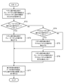
- FIG. 4 is a flowchart showing a display control method which is a processing procedure of the display control device 3 according to the first embodiment.
- the brake pedal sensor 1 monitors the operation of the brake pedal of the vehicle. If the driver has depressed the brake pedal, the brake pedal sensor 1 outputs brake pedal operation information indicating that the driver has depressed the brake pedal to the pedal operation detection unit 11 of the display control device 3. The brake pedal sensor 1 outputs brake pedal operation information indicating that the driver has not depressed the brake pedal to the pedal operation detection unit 11. If the driver has not depressed the brake pedal.
- the accelerator pedal sensor 2 monitors the operation of the accelerator pedal of the vehicle. If the driver is depressing the accelerator pedal, the accelerator pedal sensor 2 outputs accelerator pedal operation information indicating that the depressing operation is being performed to the pedal operation detection unit 11. The accelerator pedal sensor 2 outputs the accelerator pedal operation information indicating that the driver has not depressed the accelerator pedal to the pedal operation detection unit 11. If the driver has not depressed the accelerator pedal.
- the pedal operation detection unit 11 acquires the brake pedal operation information from the brake pedal sensor 1 and the accelerator pedal operation information from the accelerator pedal sensor 2 (step ST1 in FIG. 4).
- the pedal operation detection unit 11 detects the operation of the brake pedal if the brake pedal operation information indicates that the driver is depressing the brake pedal (step ST2 in FIG. 4: YES). (Step ST3 in FIG. 4). If the brake pedal operation information indicates that the driver has not depressed the brake pedal (step ST2 in FIG. 4: NO), the pedal operation detection unit 11 does not detect the operation of the brake pedal. ..
- step ST4 YES in FIG. 4
- step ST5 the operation of the accelerator pedal is detected
- step ST4 NO in FIG. 4
- step ST6 the pedal operation detection unit 11 outputs the detection result of the pedal operation to the display form switching unit 12.
- the pedal operation detection unit 11 does not detect the brake pedal operation, the accelerator pedal operation is performed. If the information indicates that the driver is depressing the accelerator pedal, the operation of the accelerator pedal is detected. However, this is only an example, and even if the operation of the brake pedal is detected, if the accelerator pedal operation information indicates that the driver is depressing the accelerator pedal, the pedal operation detection unit 11 However, the operation of the accelerator pedal may be detected.
- the display form switching unit 12 causes the instrument panel 4 to display a speed meter, a tachometer, a fuel gauge, a water temperature gauge, a distance meter, or the like.
- the display form switching unit 12 switches the display form of the meter displayed on the instrument panel 4 to which the pedal operation and the presentation information are related, according to the detection result of the pedal operation by the pedal operation detection unit 11 ( Step ST7 in FIG. 4).
- the display form switching process by the display form switching unit 12 will be specifically described.
- the display form switching unit 12 acquires the detection result of the pedal operation from the pedal operation detection unit 11. If the detection result of the pedal operation indicates that the operation of the brake pedal has been detected, the display mode switching unit 12 causes the instrument panel 4 to display a speed meter as shown in FIG.
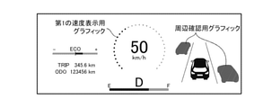
- FIG. 5 is an explanatory diagram showing a display mode of the speed meter when the operation of the brake pedal is detected.
- the instrument panel 4 shown in FIG. 5 has an odometer (indicated as "ECO" in the figure) indicating the degree of achievement of energy saving, the letter “D” indicating that the shift position is the drive position D, and the vehicle.
- FIG. 6 is an explanatory diagram showing a display mode of the speed meter when the operation of the accelerator pedal is detected.
- the instrument panel 4 shown in FIG. 6 includes an ecometer, the letter “D” indicating that the shift position is the drive position D, "50 km / h” indicating the speed of the vehicle, "123456 km” indicating the ODO, and TRIP. Is displayed as "345.6 km”. Further, on the instrument panel 4 shown in FIG. 6, a peripheral confirmation graphic is displayed around the vehicle.
- the plurality of bar-shaped figures displayed in an arc shape around "50 km / h" are the second speed display graphics showing that the speed of the vehicle is "50 km / h".
- the second speed display graphic which is a set of a plurality of bar-shaped figures, shows that the driver is operating the accelerator pedal. In other words, when the driver is operating the accelerator pedal, the display mode switching unit 12 causes the instrument panel 4 to display the second speed display graphic.
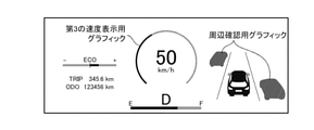
- FIG. 7 is an explanatory diagram showing a display mode of the speed meter when neither the operation of the brake pedal nor the operation of the accelerator pedal is detected.
- the instrument panel 4 shown in FIG. 7 includes an ecometer, the letter “D” indicating that the shift position is the drive position D, "50 km / h” indicating the speed of the vehicle, "123456 km” indicating the ODO, and TRIP. Is displayed as "345.6 km”. Further, on the instrument panel 4 shown in FIG. 7, a peripheral confirmation graphic is displayed around the vehicle.
- the curved figure displayed in an arc shape around "50 km / h" is a third speed display graphic showing that the speed of the vehicle is "50 km / h".
- the third speed display graphic which is a curved figure, shows that the driver has not operated the brake pedal or the accelerator pedal. In other words, when the driver is neither operating the brake pedal nor operating the accelerator pedal, the display mode switching unit 12 causes the instrument panel 4 to display the third speed display graphic.
- the display form switching unit 12 switches the shape of the speed display graphic according to the detection result of the pedal operation by the pedal operation detection unit 11.
- the display form switching unit 12 may switch, for example, the color of the speed display graphic according to the detection result of the pedal operation by the pedal operation detection unit 11.
- the color of "50 km / h" indicating the speed may be switched.
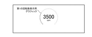
- FIG. 8 is an explanatory diagram showing a display mode of the tachometer when the operation of the brake pedal is detected.
- "3500 rpm" indicating the engine speed is displayed. Needless to say, "3500 rpm” is an example.
- the plurality of dot figures displayed in an arc shape around "3500 rpm" are the first rotation speed display graphics showing that the engine rotation speed is "3500 rpm".
- the first rotation speed display graphic which is a set of a plurality of dot figures, indicates that the driver is operating the brake pedal. In other words, when the driver is operating the brake pedal, the display mode switching unit 12 causes the instrument panel 4 to display the first rotation speed display graphic.
- FIG. 9 is an explanatory diagram showing a display mode of the tachometer when the operation of the accelerator pedal is detected.
- "3500 rpm" indicating the engine speed is displayed.
- the plurality of bar-shaped figures displayed in an arc shape around "3500 rpm” are the second rotation speed display graphics showing that the engine rotation speed is "3500 rpm”.
- the second rotation speed display graphic which is a set of a plurality of bar-shaped figures, shows that the driver is operating the accelerator pedal. In other words, when the driver is operating the accelerator pedal, the display mode switching unit 12 causes the instrument panel 4 to display the second rotation speed display graphic.
- FIG. 10 is an explanatory diagram showing a display mode of the tachometer when neither the operation of the brake pedal nor the operation of the accelerator pedal is detected.
- "3500 rpm" indicating the engine speed is displayed.
- the curved figure displayed in an arc shape around "3500 rpm” is a third rotation speed display graphic showing that the engine speed is "3500 rpm”.
- the third rotation speed display graphic which is a curved figure, shows that the driver has not operated the brake pedal or the accelerator pedal. In other words, when the driver is neither operating the brake pedal nor operating the accelerator pedal, the display mode switching unit 12 causes the instrument panel 4 to display the third rotation speed display graphic.
- the display form of the meter in which the pedal operation and the presented information are related is displayed.
- the display control device 3 is configured to include a display form switching unit 12 that switches according to the detection result of the pedal operation by the pedal operation detection unit 11. Therefore, the display control device 3 can notify the driver whether or not the pedal operation has been performed by the driver of the vehicle without providing a dedicated display area on the instrument panel 4 of the vehicle.
- Embodiment 2 when the detection result of the pedal operation by the pedal operation detection unit 11 changes, the display form switching unit 13 switches from the display form before the detection result changes to the display form after the detection result changes. At this time, the display control device 3 for displaying the animation showing the transition of the display form will be described.
- FIG. 11 is a block diagram showing the display control device 3 according to the second embodiment.
- the same reference numerals as those in FIG. 1 indicate the same or corresponding parts, and thus the description thereof will be omitted.
- FIG. 12 is a hardware configuration diagram showing the hardware of the display control device 3 according to the second embodiment. In FIG. 12, the same reference numerals as those in FIG. 2 indicate the same or corresponding parts, and thus the description thereof will be omitted.
- the display form switching unit 13 is realized by, for example, the display form switching circuit 23 shown in FIG. Similar to the display form switching unit 12 shown in FIG.
- the display form switching unit 13 causes the instrument panel 4 to display a speed meter, a tachometer, a fuel gauge, a water temperature gauge, a distance meter, or the like. Similar to the display form switching unit 12 shown in FIG. 1, the display form switching unit 13 detects the display form of the meter displayed on the instrument panel 4 to which the pedal operation and the presentation information are related. Switching is performed according to the detection result of the pedal operation by the unit 11. Unlike the display form switching unit 12 shown in FIG. 1, the display form switching unit 13 changes the detection result from the display form before the detection result changes when the detection result of the pedal operation by the pedal operation detection unit 11 changes. When switching to a later display form, an animation showing the transition of the display form is displayed.
- each of the pedal operation detection unit 11 and the display form switching unit 13, which are the components of the display control device 3, is realized by dedicated hardware as shown in FIG. That is, it is assumed that the display control device 3 is realized by the pedal operation detection circuit 21 and the display form switching circuit 23.
- Each of the pedal operation detection circuit 21 and the display mode switching circuit 23 corresponds to, for example, a single circuit, a composite circuit, a programmed processor, a parallel programmed processor, an ASIC, an FPGA, or a combination thereof.
- the components of the display control device 3 are not limited to those realized by dedicated hardware, but the display control device 3 is realized by software, firmware, or a combination of software and firmware. It is also good.
- the display control device 3 is realized by software, firmware, or the like, a program for causing the computer to execute each processing procedure in the pedal operation detection unit 11 and the display form switching unit 13 is stored in the memory 31 shown in FIG. Ru. Then, the processor 32 shown in FIG. 3 executes the program stored in the memory 31.
- FIG. 12 shows an example in which each of the components of the display control device 3 is realized by dedicated hardware
- FIG. 3 shows an example in which the display control device 3 is realized by software, firmware, or the like. ..
- this is only an example, and some components in the display control device 3 may be realized by dedicated hardware, and the remaining components may be realized by software, firmware, or the like.
- the pedal operation detection unit 11 repeatedly executes the detection process of the pedal operation of the vehicle, and repeatedly outputs the detection result of the pedal operation to the display form switching unit 13.
- the display form switching unit 13 receives the detection result of the pedal operation from the pedal operation detection unit 11, the display form of the meter in which the pedal operation and the presented information are related is changed to the detection result of the pedal operation by the pedal operation detection unit 11.
- Switch according to. the display form switching unit 13 changes the detection result from the display form before the detection result changes when the detection result of the pedal operation by the pedal operation detection unit 11 changes.
- an animation showing the transition of the display form is displayed.
- the display form switching process by the display form switching unit 13 will be specifically described.
- the display mode switching unit 13 determines whether or not the detection result of the pedal operation has changed by comparing the detection results of the pedal operation repeatedly output from the pedal operation detection unit 11 with each other. If the detection result of the pedal operation has changed, the display form switching unit 13 specifies the mode of change in the detection result. As the mode in which the detection result of the pedal operation changes, for example, the following modes (1) to (6) can be considered.
- the display form switching unit 13 When the display form switching unit 13 specifies the mode of change in the detection result, the display form switching unit 13 displays an animation showing the transition of the display form when switching from the display form before the detection result changes to the display form after the detection result changes.
- the mode of change of the detection result is, for example, the mode (1)
- the display mode switching unit 13 is in the process of switching from the display mode of the speed meter shown in FIG. 13A to the display mode of the speed meter shown in FIG. 13C.
- FIG. 13B By displaying the display form of the speed meter shown in FIG. 13B, an animation showing the transition of the display form is displayed.
- FIG. 13A is an explanatory diagram showing a display mode of the speed meter when the operation of the brake pedal is detected.
- FIG. 13B is an explanatory diagram showing the middle of switching the display form of the speed meter.
- FIG. 13C is an explanatory diagram showing a display mode of the speed meter when neither the operation of the brake pedal nor the operation of the accelerator pedal is detected.
- the broken line figure displayed in an arc shape around "50 km / h" indicates the fourth speed indicating that the speed of the vehicle is "50 km / h". It is a graphic for display. When the dot figure is stretched in the circumferential direction, it becomes a broken line figure, and when the broken line figure is stretched in the circumferential direction, it becomes a curved figure.
- the appearance of the fourth speed display graphic which is a set of a plurality of broken line figures is the appearance of the first speed display graphic which is a set of a plurality of dot figures and the appearance of the third speed display which is a curved figure.
- the display form switching unit 13 performs the first speed display graphic and the fourth speed display graphic in the order of the first speed display graphic, the fourth speed display graphic, and the third speed display graphic.
- the display mode switching unit 13 is in the process of switching from the display mode of the speed meter shown in FIG. 14A to the display mode of the speed meter shown in FIG. 14C.
- the display mode of the speed meter shown in FIG. 14B By displaying the display mode of the speed meter shown in FIG. 14B, an animation showing the transition of the display mode is displayed.
- FIG. 14A is an explanatory diagram showing a display mode of the speed meter when neither the operation of the brake pedal nor the operation of the accelerator pedal is detected.
- FIG. 14B is an explanatory diagram showing the middle of switching the display form of the speed meter.
- FIG. 14C is an explanatory diagram showing a display mode of the speed meter when the operation of the accelerator pedal is detected.
- the plurality of rod-shaped figures displayed in an arc shape around "50 km / h" indicate that the speed of the vehicle is "50 km / h". It is a graphic for speed display of.
- the line width of the plurality of bar-shaped figures included in the fifth speed display graphic is thicker than the line width of the plurality of bar-shaped figures included in the second speed display graphic. Therefore, the appearance of the fifth speed display graphic, which is a set of bar-shaped figures having a thick line width, is the appearance of the third speed display graphic, which is a curved figure, and the appearance of a bar-shaped figure having a narrow line width. It is between the appearance of the speed display graphic of 2.
- the display form switching unit 13 performs the third speed display graphic and the fifth speed display graphic in the order of the third speed display graphic, the fifth speed display graphic, and the second speed display graphic.
- the display form appears to be drawn by animation.
- the display control device 3 is configured to display an animation showing the transition of the display form when switching to. Therefore, the display control device 3 can notify the driver whether or not the pedal operation has been performed by the driver of the vehicle without providing a dedicated display area on the instrument panel 4 of the vehicle, and can also notify the driver of the transition of the pedal operation. You can inform the driver.
- any combination of the embodiments can be freely combined, any component of the embodiment can be modified, or any component can be omitted in each embodiment.
- This disclosure is suitable for display control devices and display control methods.
Landscapes
- Engineering & Computer Science (AREA)
- Chemical & Material Sciences (AREA)
- Combustion & Propulsion (AREA)
- Transportation (AREA)
- Mechanical Engineering (AREA)
- Instrument Panels (AREA)
- Controls And Circuits For Display Device (AREA)
Abstract
Description
図1は、実施の形態1に係る表示制御装置3を示す構成図である。
図2は、実施の形態1に係る表示制御装置3のハードウェアを示すハードウェア構成図である。
ブレーキペダルセンサ1は、車両のブレーキペダルの操作を監視し、運転者がブレーキペダルの踏み込み操作を行っているか否かを示すブレーキペダル操作情報を表示制御装置3に出力する。
アクセルペダルセンサ2は、車両のアクセルペダルの操作を監視し、運転者がアクセルペダルの踏み込み操作を行っているか否かを示すアクセルペダル操作情報を表示制御装置3に出力する。
表示制御装置3は、専用の表示領域を車両のインパネ4に設けることなく、車両の運転者によってペダル操作が行われたか否かを運転者に知らせる。
インパネ4の表示面積が限られている場合に、例えば、「ブレーキ」の文字を表示させる専用の表示領域を車両のインパネ4に設けると、他の情報を表示するための領域が相対的に狭くなり、運転者が、他の情報の確認が困難になることがある。表示制御装置3は、専用の表示領域を車両のインパネ4に設ける必要がないため、他の情報を表示するための領域が相対的に狭くなることがない。
インパネ4は、車両の運転席に設けられた計器盤であり、速度メータ、タコメータ、燃料計、水温計、又は、距離計等が表示される。
図1に示す表示制御装置3では、インパネ4が、いわゆるデジタルメータであるものを想定しているが、アナログメータであってもよい。
ペダル操作検出部11は、例えば、図2に示すペダル操作検出回路21によって実現される。
ペダル操作検出部11は、ブレーキペダルセンサ1から、ブレーキペダル操作情報を取得し、アクセルペダルセンサ2から、アクセルペダル操作情報を取得する。
ペダル操作検出部11は、車両のペダル操作を検出する。
即ち、ペダル操作検出部11は、ブレーキペダル操作情報が、運転者がブレーキペダルの踏み込み操作を行っている旨を示していれば、ブレーキペダルの操作を検出する。
ペダル操作検出部11は、アクセルペダル操作情報が、運転者がアクセルペダルの踏み込み操作を行っている旨を示していれば、アクセルペダルの操作を検出する。
ペダル操作検出部11は、ペダル操作の検出結果を表示形態切替部12に出力する。
表示形態切替部12は、速度メータ、タコメータ、燃料計、水温計、又は、距離計等をインパネ4に表示させる。
表示形態切替部12は、インパネ4に表示されているメータのうち、ペダル操作と提示情報が関連しているメータの表示形態を、ペダル操作検出部11によるペダル操作の検出結果に応じて切り替える。
ペダル操作と提示情報が関連するメータとして、速度メータ、又は、タコメータが考えられる。
したがって、表示形態切替部12は、速度メータの表示形態、又は、タコメータの表示形態を、ペダル操作検出部11によるペダル操作の検出結果に応じて切り替える。
ペダル操作検出回路21及び表示形態切替回路22のそれぞれは、例えば、単一回路、複合回路、プログラム化したプロセッサ、並列プログラム化したプロセッサ、ASIC(Application Specific Integrated Circuit)、FPGA(Field-Programmable Gate Array)、又は、これらを組み合わせたものが該当する。
ソフトウェア又はファームウェアは、プログラムとして、コンピュータのメモリに格納される。コンピュータは、プログラムを実行するハードウェアを意味し、例えば、CPU(Central Processing Unit)、中央処理装置、処理装置、演算装置、マイクロプロセッサ、マイクロコンピュータ、プロセッサ、あるいは、DSP(Digital Signal Processor)が該当する。
表示制御装置3が、ソフトウェア又はファームウェア等によって実現される場合、ペダル操作検出部11及び表示形態切替部12におけるそれぞれの処理手順をコンピュータに実行させるためのプログラムがメモリ31に格納される。そして、コンピュータのプロセッサ32がメモリ31に格納されているプログラムを実行する。
図4は、実施の形態1に係る表示制御装置3の処理手順である表示制御方法を示すフローチャートである。
ブレーキペダルセンサ1は、車両のブレーキペダルの操作を監視する。
ブレーキペダルセンサ1は、運転者がブレーキペダルの踏み込み操作を行っていれば、踏み込み操作を行っている旨を示すブレーキペダル操作情報を表示制御装置3のペダル操作検出部11に出力する。
ブレーキペダルセンサ1は、運転者がブレーキペダルの踏み込み操作を行っていなければ、踏み込み操作を行っていない旨を示すブレーキペダル操作情報をペダル操作検出部11に出力する。
アクセルペダルセンサ2は、運転者がアクセルペダルの踏み込み操作を行っていれば、踏み込み操作を行っている旨を示すアクセルペダル操作情報をペダル操作検出部11に出力する。
アクセルペダルセンサ2は、運転者がアクセルペダルの踏み込み操作を行っていなければ、踏み込み操作を行っていない旨を示すアクセルペダル操作情報をペダル操作検出部11に出力する。
ペダル操作検出部11は、ブレーキペダル操作情報が、運転者がブレーキペダルの踏み込み操作を行っている旨を示していれば(図4のステップST2:YESの場合)、ブレーキペダルの操作を検出する(図4のステップST3)。
ペダル操作検出部11は、ブレーキペダル操作情報が、運転者がブレーキペダルの踏み込み操作を行っていない旨を示していれば(図4のステップST2:NOの場合)、ブレーキペダルの操作を検出しない。
ペダル操作検出部11は、運転者がアクセルペダルの踏み込み操作を行っていない旨を示していれば(図4のステップST4:NOの場合)、アクセルペダルの操作を検出しない。即ち、ペダル操作検出部11は、ブレーキペダルの操作及びアクセルペダルの操作の双方を検出しない(図4のステップST6)。
ペダル操作検出部11は、ペダル操作の検出結果を表示形態切替部12に出力する。
表示形態切替部12は、インパネ4に表示されているメータのうち、ペダル操作と提示情報が関連しているメータの表示形態を、ペダル操作検出部11によるペダル操作の検出結果に応じて切り替える(図4のステップST7)。
以下、表示形態切替部12による表示形態の切替処理を具体的に説明する。
表示形態切替部12は、ペダル操作の検出結果が、ブレーキペダルの操作を検出した旨を示していれば、図5に示すような速度メータをインパネ4に表示させる。
図5は、ブレーキペダルの操作が検出されているときの速度メータの表示形態を示す説明図である。
図5に示すインパネ4には、省エネルギーの達成度を示すエコメータ(図中、「ECO」と表記されている)、シフトポジションがドライブポジションDである旨を示す「D」の文字と、車両の速度を示す「50km/h」と、車両の総走行距離(以下「ODO」という)を示す「123456km」と、車両の区間走行距離(以下「TRIP」という)を示す「345.6km」とが表示されている。言うまでもないが、「50km/h」、「123456km」及び「345.6km」は、一例である。
また、図5に示すインパネ4には、車両の周辺に存在している物体等を示す周辺確認用グラフィックが車両の周辺に表示されている。
「50km/h」の周囲に円弧状に表示されている複数のドット図形は、車両の速度が「50km/h」であることを表している第1の速度表示用グラフィックである。
複数のドット図形の集合である第1の速度表示用グラフィックは、運転者がブレーキペダルの操作を行っていることを表している。換言すると、運転者がブレーキペダルの操作を行っているとき、表示形態切替部12は、第1の速度表示用グラフィックをインパネ4に表示させる。
図6は、アクセルペダルの操作が検出されているときの速度メータの表示形態を示す説明図である。
図6に示すインパネ4には、エコメータ、シフトポジションがドライブポジションDである旨を示す「D」の文字と、車両の速度を示す「50km/h」と、ODOを示す「123456km」と、TRIPを示す「345.6km」とが表示されている。
また、図6に示すインパネ4には、周辺確認用グラフィックが車両の周辺に表示されている。
「50km/h」の周囲に円弧状に表示されている複数の棒状図形は、車両の速度が「50km/h」であることを表している第2の速度表示用グラフィックである。
複数の棒状図形の集合である第2の速度表示用グラフィックは、運転者がアクセルペダルの操作を行っていることを表している。換言すると、運転者がアクセルペダルの操作を行っているとき、表示形態切替部12は、第2の速度表示用グラフィックをインパネ4に表示させる。
図7は、ブレーキペダルの操作及びアクセルペダルの操作のいずれも検出されていないときの速度メータの表示形態を示す説明図である。
図7に示すインパネ4には、エコメータ、シフトポジションがドライブポジションDである旨を示す「D」の文字と、車両の速度を示す「50km/h」と、ODOを示す「123456km」と、TRIPを示す「345.6km」とが表示されている。
また、図7に示すインパネ4には、周辺確認用グラフィックが車両の周辺に表示されている。
「50km/h」の周囲に円弧状に表示されている曲線図形は、車両の速度が「50km/h」であることを表している第3の速度表示用グラフィックである。
曲線図形である第3の速度表示用グラフィックは、運転者が、ブレーキペダルの操作及びアクセルペダルの操作のいずれも行っていないことを表している。換言すると、運転者が、ブレーキペダルの操作及びアクセルペダルの操作のいずれも行っていないとき、表示形態切替部12は、第3の速度表示用グラフィックをインパネ4に表示させる。
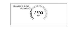
図8は、ブレーキペダルの操作が検出されているときのタコメータの表示形態を示す説明図である。
図8に示すインパネ4には、エンジンの回転数を示す「3500rpm」が表示されている。言うまでもないが、「3500rpm」は、一例である。
「3500rpm」の周囲に円弧状に表示されている複数のドット図形は、エンジンの回転数が「3500rpm」であることを表している第1の回転数表示用グラフィックである。
複数のドット図形の集合である第1の回転数表示用グラフィックは、運転者がブレーキペダルの操作を行っていることを表している。換言すると、運転者がブレーキペダルの操作を行っているとき、表示形態切替部12は、第1の回転数表示用グラフィックをインパネ4に表示させる。
図9に示すインパネ4には、エンジンの回転数を示す「3500rpm」が表示されている。
「3500rpm」の周囲に円弧状に表示されている複数の棒状図形は、エンジンの回転数が「3500rpm」であることを表している第2の回転数表示用グラフィックである。
複数の棒状図形の集合である第2の回転数表示用グラフィックは、運転者がアクセルペダルの操作を行っていることを表している。換言すると、運転者がアクセルペダルの操作を行っているとき、表示形態切替部12は、第2の回転数表示用グラフィックをインパネ4に表示させる。
図10に示すインパネ4には、エンジンの回転数を示す「3500rpm」が表示されている。
「3500rpm」の周囲に円弧状に表示されている曲線図形は、エンジンの回転数が「3500rpm」であることを表している第3の回転数表示用グラフィックである。
曲線図形である第3の回転数表示用グラフィックは、運転者が、ブレーキペダルの操作及びアクセルペダルの操作のいずれも行っていないことを表している。換言すると、運転者が、ブレーキペダルの操作及びアクセルペダルの操作のいずれも行っていないとき、表示形態切替部12は、第3の回転数表示用グラフィックをインパネ4に表示させる。
実施の形態2では、表示形態切替部13が、ペダル操作検出部11によるペダル操作の検出結果が変化すると、検出結果が変化する前の表示形態から、検出結果が変化した後の表示形態に切り替える際、表示形態の遷移を示すアニメーションを表示させる表示制御装置3について説明する。
図12は、実施の形態2に係る表示制御装置3のハードウェアを示すハードウェア構成図である。図12において、図2と同一符号は同一又は相当部分を示すので説明を省略する。
表示形態切替部13は、例えば、図12に示す表示形態切替回路23によって実現される。
表示形態切替部13は、図1に示す表示形態切替部12と同様に、速度メータ、タコメータ、燃料計、水温計、又は、距離計等をインパネ4に表示させる。
表示形態切替部13は、図1に示す表示形態切替部12と同様に、インパネ4に表示されているメータのうち、ペダル操作と提示情報が関連しているメータの表示形態を、ペダル操作検出部11によるペダル操作の検出結果に応じて切り替える。
表示形態切替部13は、図1に示す表示形態切替部12と異なり、ペダル操作検出部11によるペダル操作の検出結果が変化すると、検出結果が変化する前の表示形態から、検出結果が変化した後の表示形態に切り替える際、表示形態の遷移を示すアニメーションを表示させる。
ペダル操作検出回路21及び表示形態切替回路23のそれぞれは、例えば、単一回路、複合回路、プログラム化したプロセッサ、並列プログラム化したプロセッサ、ASIC、FPGA、又は、これらを組み合わせたものが該当する。
表示制御装置3が、ソフトウェア又はファームウェア等によって実現される場合、ペダル操作検出部11及び表示形態切替部13におけるそれぞれの処理手順をコンピュータに実行させるためのプログラムが図3に示すメモリ31に格納される。そして、図3に示すプロセッサ32がメモリ31に格納されているプログラムを実行する。
ただし、表示形態切替部13以外は、図1に示す表示制御装置3と同様であるため、ここでは、主に、表示形態切替部13の動作を説明する。
ペダル操作検出部11は、車両のペダル操作の検出処理を繰り返し実施し、ペダル操作の検出結果を表示形態切替部13に繰り返し出力する。
表示形態切替部13は、図1に示す表示形態切替部12と異なり、ペダル操作検出部11によるペダル操作の検出結果が変化すると、検出結果が変化する前の表示形態から、検出結果が変化した後の表示形態に切り替える際、表示形態の遷移を示すアニメーションを表示させる。
以下、表示形態切替部13による表示形態の切替処理を具体的に説明する。
表示形態切替部13は、ペダル操作の検出結果が変化していれば、検出結果の変化の態様を特定する。
ペダル操作の検出結果が変化する態様としては、例えば、以下の態様(1)~(6)が考えられる。
(1)ブレーキペダル操作が「有り」からペダル操作が「無し」への変化
(2)ペダル操作が「無し」からブレーキペダル操作が「有り」への変化
(3)アクセルペダル操作が「有り」からペダル操作が「無し」への変化
(4)ペダル操作が「無し」からアクセルペダル操作が「有り」への変化
(5)ブレーキペダル操作が「有り」からアクセルペダル操作が「有り」への変化
(6)アクセルペダル操作が「有り」からブレーキペダル操作が「有り」への変化
ペダル操作が「無し」は、ブレーキペダルの操作及びアクセルペダルの操作のいずれも検出されていないことを意味する。
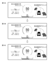
即ち、表示形態切替部13は、検出結果の変化の態様が、例えば、態様(1)であれば、図13Aに示す速度メータの表示形態から、図13Cに示す速度メータの表示形態に切り替える途中に、図13Bに示す速度メータの表示形態を表示させることによって、表示形態の遷移を示すアニメーションを表示させる。
図13Aは、ブレーキペダルの操作が検出されているときの速度メータの表示形態を示す説明図である。
図13Bは、速度メータの表示形態の切り替え途中を示す説明図である。
図13Cは、ブレーキペダルの操作及びアクセルペダルの操作のいずれも検出されていないときの速度メータの表示形態を示す説明図である。
図13Bに示す速度メータの表示形態において、「50km/h」の周囲に円弧状に表示されている破線図形は、車両の速度が「50km/h」であることを表している第4の速度表示用グラフィックである。
ドット図形を円周方向に伸ばすと、破線図形になり、破線図形を円周方向に伸ばすと、曲線図形になる。したがって、複数の破線図形の集合である第4の速度表示用グラフィックの見かけは、複数のドット図形の集合である第1の速度表示用グラフィックの見かけと、曲線図形である第3の速度表示用グラフィックの見かけとの間になる。したがって、表示形態切替部13が、第1の速度表示用グラフィック、第4の速度表示用グラフィック、第3の速度表示用グラフィックの順番で、第1の速度表示用グラフィック、第4の速度表示用グラフィック及び第3の速度表示用グラフィックのそれぞれを表示させることにより、表示形態がアニメーションで描画されたように見える。
図14Aは、ブレーキペダルの操作及びアクセルペダルの操作のいずれも検出されていないときの速度メータの表示形態を示す説明図である。
図14Bは、速度メータの表示形態の切り替え途中を示す説明図である。
図14Cは、アクセルペダルの操作が検出されているときの速度メータの表示形態を示す説明図である。
図14Bに示す速度メータの表示形態において、「50km/h」の周囲に円弧状に表示されている複数の棒状図形は、車両の速度が「50km/h」であることを表している第5の速度表示用グラフィックである。
第5の速度表示用グラフィックに含まれている複数の棒状図形の線幅が、第2の速度表示用グラフィックに含まれている複数の棒状図形の線幅よりも太い。このため、線幅が太い棒状図形の集合である第5の速度表示用グラフィックの見かけは、曲線図形である第3の速度表示用グラフィックの見かけと、線幅が狭い棒状図形の集合である第2の速度表示用グラフィックの見かけとの間になる。したがって、表示形態切替部13が、第3の速度表示用グラフィック、第5の速度表示用グラフィック、第2の速度表示用グラフィックの順番で、第3の速度表示用グラフィック、第5の速度表示用グラフィック及び第2の速度表示用グラフィックのそれぞれを表示させることにより、表示形態がアニメーションで描画されたように見える。
Claims (5)
- 車両のペダル操作を検出するペダル操作検出部と、
前記車両のインストルメントパネルに表示されているメータのうち、前記ペダル操作と提示情報が関連しているメータの表示形態を、前記ペダル操作検出部によるペダル操作の検出結果に応じて切り替える表示形態切替部と
を備えた表示制御装置。 - 前記ペダル操作と提示情報が関連するメータは、速度メータ、又は、タコメータであることを特徴とする請求項1記載の表示制御装置。
- 前記ペダル操作検出部により検出されるペダル操作は、ブレーキペダルの操作、又は、アクセルペダルの操作であることを特徴とする請求項1記載の表示制御装置。
- 前記表示形態切替部は、前記ペダル操作検出部によるペダル操作の検出結果が変化すると、前記検出結果が変化する前の表示形態から、前記検出結果が変化した後の表示形態に切り替える際、表示形態の遷移を示すアニメーションを表示させることを特徴とする請求項1記載の表示制御装置。
- ペダル操作検出部が、車両のペダル操作を検出し、
表示形態切替部が、前記車両のインストルメントパネルに表示されているメータのうち、前記ペダル操作と提示情報が関連しているメータの表示形態を、前記ペダル操作検出部によるペダル操作の検出結果に応じて切り替える
表示制御方法。
Priority Applications (5)
| Application Number | Priority Date | Filing Date | Title |
|---|---|---|---|
| PCT/JP2020/028137 WO2022018805A1 (ja) | 2020-07-20 | 2020-07-20 | 表示制御装置及び表示制御方法 |
| DE112020007217.7T DE112020007217B4 (de) | 2020-07-20 | 2020-07-20 | Anzeigesteuerungseinrichtung und Anzeigesteuerungsverfahren |
| CN202080102791.2A CN115867453B (zh) | 2020-07-20 | 2020-07-20 | 显示控制装置和显示控制方法 |
| JP2020568478A JP6980138B1 (ja) | 2020-07-20 | 2020-07-20 | 表示制御装置及び表示制御方法 |
| US18/071,641 US12187126B2 (en) | 2020-07-20 | 2022-11-30 | Display control device and display control method |
Applications Claiming Priority (1)
| Application Number | Priority Date | Filing Date | Title |
|---|---|---|---|
| PCT/JP2020/028137 WO2022018805A1 (ja) | 2020-07-20 | 2020-07-20 | 表示制御装置及び表示制御方法 |
Related Child Applications (1)
| Application Number | Title | Priority Date | Filing Date |
|---|---|---|---|
| US18/071,641 Continuation US12187126B2 (en) | 2020-07-20 | 2022-11-30 | Display control device and display control method |
Publications (1)
| Publication Number | Publication Date |
|---|---|
| WO2022018805A1 true WO2022018805A1 (ja) | 2022-01-27 |
Family
ID=78870749
Family Applications (1)
| Application Number | Title | Priority Date | Filing Date |
|---|---|---|---|
| PCT/JP2020/028137 Ceased WO2022018805A1 (ja) | 2020-07-20 | 2020-07-20 | 表示制御装置及び表示制御方法 |
Country Status (5)
| Country | Link |
|---|---|
| US (1) | US12187126B2 (ja) |
| JP (1) | JP6980138B1 (ja) |
| CN (1) | CN115867453B (ja) |
| DE (1) | DE112020007217B4 (ja) |
| WO (1) | WO2022018805A1 (ja) |
Citations (3)
| Publication number | Priority date | Publication date | Assignee | Title |
|---|---|---|---|---|
| KR101491330B1 (ko) * | 2013-10-17 | 2015-02-06 | 현대자동차주식회사 | 클러스터 표시 장치 및 방법 |
| JP2018193050A (ja) * | 2017-05-18 | 2018-12-06 | 三菱自動車工業株式会社 | ハイブリッド車両の表示装置 |
| JP2020012840A (ja) * | 2019-09-17 | 2020-01-23 | 株式会社ユピテル | システム及びプログラム |
Family Cites Families (12)
| Publication number | Priority date | Publication date | Assignee | Title |
|---|---|---|---|---|
| JP2004196276A (ja) | 2002-12-17 | 2004-07-15 | Masabumi Kanda | 自動車用操作情報表示装置 |
| JP2005067576A (ja) | 2003-08-22 | 2005-03-17 | Hiroshi Kojima | ブレーキランプ表示装置 |
| JP2005227008A (ja) * | 2004-02-10 | 2005-08-25 | Nissan Motor Co Ltd | 走行状況アドバイスシステム |
| US7729514B2 (en) | 2004-06-07 | 2010-06-01 | Sharp Kabushiki Kaisha | Display device, vehicle, method for displaying, program for displaying and recording medium of same |
| JP2012158208A (ja) * | 2011-01-31 | 2012-08-23 | Iseki & Co Ltd | トラクタ |
| JP2012251449A (ja) * | 2011-06-01 | 2012-12-20 | Toyota Motor Corp | 動力装置の制御装置 |
| JP6384892B2 (ja) * | 2013-07-17 | 2018-09-05 | 日本精機株式会社 | 車両用表示装置 |
| DE112013007563T5 (de) | 2013-10-30 | 2016-07-14 | Honda Motor Co., Ltd. | Gerät zum Steuern/Regeln einer Pedalauflagekraft |
| JP6524501B2 (ja) | 2015-06-11 | 2019-06-05 | パナソニックIpマネジメント株式会社 | 車両制御装置、車両制御方法および車両制御プログラム |
| US11173926B2 (en) | 2016-08-05 | 2021-11-16 | Mitsubishi Electric Corporation | Operation authority management apparatus and operation authority management method |
| JP7245019B2 (ja) * | 2018-09-28 | 2023-03-23 | カワサキモータース株式会社 | 走行データ表示方法、プログラム及びシステム |
| JP7253708B2 (ja) | 2020-03-17 | 2023-04-07 | パナソニックIpマネジメント株式会社 | 情報処理装置、車両及び情報処理方法 |
-
2020
- 2020-07-20 CN CN202080102791.2A patent/CN115867453B/zh active Active
- 2020-07-20 JP JP2020568478A patent/JP6980138B1/ja active Active
- 2020-07-20 DE DE112020007217.7T patent/DE112020007217B4/de active Active
- 2020-07-20 WO PCT/JP2020/028137 patent/WO2022018805A1/ja not_active Ceased
-
2022
- 2022-11-30 US US18/071,641 patent/US12187126B2/en active Active
Patent Citations (3)
| Publication number | Priority date | Publication date | Assignee | Title |
|---|---|---|---|---|
| KR101491330B1 (ko) * | 2013-10-17 | 2015-02-06 | 현대자동차주식회사 | 클러스터 표시 장치 및 방법 |
| JP2018193050A (ja) * | 2017-05-18 | 2018-12-06 | 三菱自動車工業株式会社 | ハイブリッド車両の表示装置 |
| JP2020012840A (ja) * | 2019-09-17 | 2020-01-23 | 株式会社ユピテル | システム及びプログラム |
Also Published As
| Publication number | Publication date |
|---|---|
| CN115867453A (zh) | 2023-03-28 |
| US12187126B2 (en) | 2025-01-07 |
| JP6980138B1 (ja) | 2021-12-15 |
| DE112020007217B4 (de) | 2025-01-30 |
| DE112020007217T5 (de) | 2023-03-09 |
| JPWO2022018805A1 (ja) | 2022-01-27 |
| US20230089233A1 (en) | 2023-03-23 |
| CN115867453B (zh) | 2025-05-02 |
Similar Documents
| Publication | Publication Date | Title |
|---|---|---|
| US8339400B2 (en) | Graphic display meter | |
| JP2011105253A (ja) | 表示装置 | |
| JP2010030331A (ja) | 車両用表示装置 | |
| JP4839131B2 (ja) | グラフィックメータ表示装置 | |
| CN108407617A (zh) | 显示装置 | |
| JP2007314100A (ja) | ハイブリッド車両の表示装置 | |
| JP5344372B2 (ja) | 車両用表示装置 | |
| JP2007303894A (ja) | グラフィックメータ表示装置 | |
| JP6980138B1 (ja) | 表示制御装置及び表示制御方法 | |
| JP5187575B2 (ja) | 車両用表示装置 | |
| JP6385138B2 (ja) | 車載表示制御装置および車載表示制御方法 | |
| JP6079155B2 (ja) | 表示制御装置 | |
| JP6929476B1 (ja) | 表示制御装置及び表示制御方法 | |
| JP2009058275A (ja) | 車両用表示装置 | |
| JP6211501B2 (ja) | 車両用表示装置 | |
| JP5210973B2 (ja) | 自動車用計器、及び、自動車用計器の表示方法 | |
| JP2011075344A (ja) | 車両用表示装置 | |
| JP2009058276A (ja) | 車両用表示装置 | |
| JP2010107534A (ja) | 車載表示装置 | |
| JP4930717B2 (ja) | 車両用表示装置 | |
| JP2005239021A (ja) | 車両用表示装置 | |
| JP5441252B2 (ja) | 可動式メータおよびその表示制御方法 | |
| US12275304B2 (en) | Image display control device, image display control method, and computer-readable storage medium | |
| JP2014153231A (ja) | 車両用表示装置 | |
| JP4164913B2 (ja) | 車両用表示装置 |
Legal Events
| Date | Code | Title | Description |
|---|---|---|---|
| ENP | Entry into the national phase |
Ref document number: 2020568478 Country of ref document: JP Kind code of ref document: A |
|
| 121 | Ep: the epo has been informed by wipo that ep was designated in this application |
Ref document number: 20946363 Country of ref document: EP Kind code of ref document: A1 |
|
| 122 | Ep: pct application non-entry in european phase |
Ref document number: 20946363 Country of ref document: EP Kind code of ref document: A1 |
|
| WWG | Wipo information: grant in national office |
Ref document number: 202080102791.2 Country of ref document: CN |