WO2022014524A1 - 内視鏡及び処置具起立機構 - Google Patents
内視鏡及び処置具起立機構 Download PDFInfo
- Publication number
- WO2022014524A1 WO2022014524A1 PCT/JP2021/026098 JP2021026098W WO2022014524A1 WO 2022014524 A1 WO2022014524 A1 WO 2022014524A1 JP 2021026098 W JP2021026098 W JP 2021026098W WO 2022014524 A1 WO2022014524 A1 WO 2022014524A1
- Authority
- WO
- WIPO (PCT)
- Prior art keywords
- tip
- treatment tool
- wire
- stand
- wall portion
- Prior art date
- Legal status (The legal status is an assumption and is not a legal conclusion. Google has not performed a legal analysis and makes no representation as to the accuracy of the status listed.)
- Ceased
Links
Images


Classifications
-
- A—HUMAN NECESSITIES
- A61—MEDICAL OR VETERINARY SCIENCE; HYGIENE
- A61B—DIAGNOSIS; SURGERY; IDENTIFICATION
- A61B1/00—Instruments for performing medical examinations of the interior of cavities or tubes of the body by visual or photographical inspection, e.g. endoscopes; Illuminating arrangements therefor
- A61B1/00064—Constructional details of the endoscope body
- A61B1/00071—Insertion part of the endoscope body
- A61B1/0008—Insertion part of the endoscope body characterised by distal tip features
- A61B1/00098—Deflecting means for inserted tools
-
- A—HUMAN NECESSITIES
- A61—MEDICAL OR VETERINARY SCIENCE; HYGIENE
- A61B—DIAGNOSIS; SURGERY; IDENTIFICATION
- A61B1/00—Instruments for performing medical examinations of the interior of cavities or tubes of the body by visual or photographical inspection, e.g. endoscopes; Illuminating arrangements therefor
- A61B1/00112—Connection or coupling means
- A61B1/00121—Connectors, fasteners and adapters, e.g. on the endoscope handle
- A61B1/00128—Connectors, fasteners and adapters, e.g. on the endoscope handle mechanical, e.g. for tubes or pipes
-
- A—HUMAN NECESSITIES
- A61—MEDICAL OR VETERINARY SCIENCE; HYGIENE
- A61B—DIAGNOSIS; SURGERY; IDENTIFICATION
- A61B1/00—Instruments for performing medical examinations of the interior of cavities or tubes of the body by visual or photographical inspection, e.g. endoscopes; Illuminating arrangements therefor
- A61B1/00131—Accessories for endoscopes
- A61B1/00137—End pieces at either end of the endoscope, e.g. caps, seals or forceps plugs
-
- A—HUMAN NECESSITIES
- A61—MEDICAL OR VETERINARY SCIENCE; HYGIENE
- A61B—DIAGNOSIS; SURGERY; IDENTIFICATION
- A61B1/00—Instruments for performing medical examinations of the interior of cavities or tubes of the body by visual or photographical inspection, e.g. endoscopes; Illuminating arrangements therefor
- A61B1/012—Instruments for performing medical examinations of the interior of cavities or tubes of the body by visual or photographical inspection, e.g. endoscopes; Illuminating arrangements therefor characterised by internal passages or accessories therefor
- A61B1/018—Instruments for performing medical examinations of the interior of cavities or tubes of the body by visual or photographical inspection, e.g. endoscopes; Illuminating arrangements therefor characterised by internal passages or accessories therefor for receiving instruments
-
- A—HUMAN NECESSITIES
- A61—MEDICAL OR VETERINARY SCIENCE; HYGIENE
- A61B—DIAGNOSIS; SURGERY; IDENTIFICATION
- A61B8/00—Diagnosis using ultrasonic, sonic or infrasonic waves
- A61B8/08—Clinical applications
- A61B8/0833—Clinical applications involving detecting or locating foreign bodies or organic structures
- A61B8/0841—Clinical applications involving detecting or locating foreign bodies or organic structures for locating instruments
-
- A—HUMAN NECESSITIES
- A61—MEDICAL OR VETERINARY SCIENCE; HYGIENE
- A61B—DIAGNOSIS; SURGERY; IDENTIFICATION
- A61B8/00—Diagnosis using ultrasonic, sonic or infrasonic waves
- A61B8/12—Diagnosis using ultrasonic, sonic or infrasonic waves in body cavities or body tracts, e.g. by using catheters
-
- A—HUMAN NECESSITIES
- A61—MEDICAL OR VETERINARY SCIENCE; HYGIENE
- A61B—DIAGNOSIS; SURGERY; IDENTIFICATION
- A61B8/00—Diagnosis using ultrasonic, sonic or infrasonic waves
- A61B8/44—Constructional features of the ultrasonic, sonic or infrasonic diagnostic device
- A61B8/4444—Constructional features of the ultrasonic, sonic or infrasonic diagnostic device related to the probe
- A61B8/445—Details of catheter construction
-
- G—PHYSICS
- G02—OPTICS
- G02B—OPTICAL ELEMENTS, SYSTEMS OR APPARATUS
- G02B23/00—Telescopes, e.g. binoculars; Periscopes; Instruments for viewing the inside of hollow bodies; Viewfinders; Optical aiming or sighting devices
- G02B23/24—Instruments or systems for viewing the inside of hollow bodies, e.g. fibrescopes
-
- A—HUMAN NECESSITIES
- A61—MEDICAL OR VETERINARY SCIENCE; HYGIENE
- A61B—DIAGNOSIS; SURGERY; IDENTIFICATION
- A61B1/00—Instruments for performing medical examinations of the interior of cavities or tubes of the body by visual or photographical inspection, e.g. endoscopes; Illuminating arrangements therefor
- A61B1/00064—Constructional details of the endoscope body
- A61B1/00071—Insertion part of the endoscope body
- A61B1/0008—Insertion part of the endoscope body characterised by distal tip features
- A61B1/00101—Insertion part of the endoscope body characterised by distal tip features the distal tip features being detachable
Definitions
- the present invention relates to an endoscope and a treatment tool standing mechanism provided with a treatment tool standing stand that changes the direction of drawing out the treatment tool on the tip end side of the insertion portion.
- various treatment tools are introduced from the treatment tool introduction port provided in the operation part, and this treatment tool is taken out from the treatment tool outlet opened at the tip of the insertion part and used for treatment.
- a treatment tool such as a guide wire or a contrast tube is used.
- Treatment tools such as puncture needles are used in ultrasonic endoscopes.
- treatment tools such as forceps or snares are used.
- Such a treatment tool needs to change the lead-out direction at the tip in order to treat a desired position in the subject.
- the tip of the insertion portion is provided with a treatment tool standing mechanism that changes the direction in which the treatment tool is derived (see Patent Document 1).
- the treatment tool standing mechanism has a treatment tool standing table, and the posture of the treatment tool standing table is displaced between the standing position and the lying position.
- a wire traction method open type mechanism in which the tip of an operating wire is directly attached to a standing table and the base end of the operating wire is connected to an operating lever provided in the operating portion.
- This mechanism changes the posture of the standing table between the standing position and the lying down position by rotating the standing table around the rotation axis by pushing and pulling the operation wire with the operating lever.
- Patent Document 5 a tip portion including a treatment tool standing table, an operation wire fixed to a side portion of the treatment tool standing table, and a pair of side walls constituting the standing table accommodating space for accommodating the treatment tool standing table.
- An endoscope comprising a main body is disclosed.
- the side wall on the side facing the side of the above-mentioned treatment tool standing table (hereinafter referred to as the facing side wall) fills the gap on the lower side of the operation wire. It has a shape.
- the facing side wall prevents the treatment tool from slipping into the lower side of the operation wire.
- the present invention has been made in view of such circumstances, and it is possible to improve the accessibility of the cleaning brush, prevent the tip body from being worn, and prevent the treatment tool from slipping into the lower side of the operation wire. It is an object of the present invention to provide an endoscope and a treatment tool standing mechanism.
- the endoscope for achieving the object of the present invention is located at the operation portion provided with the operation member, the insertion portion provided on the tip side of the operation portion and inserted into the subject, and the tip of the insertion portion.
- One direction in the first direction which is the opening base end wall portion and the first wall portion extending from the base end wall portion to the tip end side of the tip portion main body and perpendicular to the longitudinal axis of the tip portion main body with respect to the outlet.
- a treatment tool that can rotate between the lying down position and the upright position. It is provided with a treatment tool standing table having a table tip portion, a wire connecting portion provided at the standing table tip portion, and an operation wire connected to the wire connecting portion to rotate the treatment tool standing table, and has a longitudinal axis.
- the wire tip of the operation wire connected to the wire connection is located on the other direction side of the stand body, and the second wall
- at least a part of the first wall surface has a shape along the locus of the wire connecting portion that rotates around the rotation axis, and the first wall surface is provided at a position on the one-way side of the first wall surface and rotates around the rotation axis. It has a second wall surface having a shape along the trajectory of the moving stand body, and when viewed from the second direction, the second wall surface overlaps with at least a part of the wire tip in the first direction. is doing.
- the second wall surface can prevent the treatment tool from slipping into the lower side of the wire tip of the operation wire.
- the wire tip has a shape protruding from the tip of the stand to the other direction from the main body of the stand.
- the second wall surface is provided at a position on the one-way side of the central axis of the wire tip when viewed from the second direction.
- the second wall portion has a stepped surface formed between the first wall surface and the second wall surface, and the stepped surface rotates about a rotation axis. It has a shape along the trajectory of the tip of the wire. As a result, it is possible to prevent the treatment tool from slipping into the lower side of the wire tip portion of the operation wire.
- the stepped surface is formed in an arc shape when viewed from the first direction.
- the first wall surface is provided on the other side of the operation wire when viewed from the second direction.
- the wall thickness of the tip of the standing table can be increased.
- the tip main body is a cap having a base end wall portion and a first wall portion
- the standing table accommodating space forming member is a cap having a second wall portion
- an opening window is formed at the tip of the cap to expose the standing space when viewed from the tip side of the cap.
- the standing table accommodating space forming member has a base end wall portion, a first wall portion, and a second wall portion, and is provided on the tip end side of the tip portion main body. Equipped with an ultrasonic transducer.
- an insert molded body in which a treatment tool standing table and an operation wire are integrated is provided.
- the treatment tool stand and the operation wire are separately formed.
- the treatment tool standing mechanism for achieving the object of the present invention is provided on the operation portion provided with the operation member, the insertion portion provided on the tip side of the operation portion and inserted into the subject, and the tip of the insertion portion.
- the treatment tool standing mechanism that is attached to the tip body of the endoscope provided with the positioned tip body and changes the direction in which the treatment tool is taken out, it is detachably attached to the tip body to form an upright stand accommodating space.
- the first wall portion is provided at a position on the one-way side in the first direction perpendicular to the longitudinal axis of the tip portion main body with respect to the outlet, and the standing stand accommodating space forming member is provided.
- It is a treatment tool standing table that is arranged in the standing table accommodation space and is rotatable between the lying down position and the standing position around the rotation axis parallel to the first direction with the facing second wall portion.
- a treatment tool having a stand main body portion rotatably held by a rotating shaft, a stand tip portion provided on the tip end side of the stand stand main body, and a wire connection portion provided on the stand tip tip portion. It is provided with an upright stand and an operating wire connected to the wire connection portion to rotate the treatment tool upright base, and is provided at the wire connection portion when viewed from a second direction perpendicular to both the longitudinal axis and the first direction.
- the wire tip of the connected operation wire is located on the other side of the stand body, and the second wall follows the trajectory of the wire connection that rotates at least partly around the rotation axis.
- first wall surface having a shape and a second wall surface having a shape along the locus of an upright stand main body that is provided at a position on the one-way side of the first wall surface and rotates about a rotation axis.
- the second wall surface overlaps with at least a part of the wire tip portion in the first direction.
- the second wall surface is provided at a position on the one-way side of the central axis of the wire tip when viewed from the second direction.
- the present invention can improve the accessibility of the cleaning brush, prevent the tip body from being worn, and prevent the treatment tool from slipping into the lower side of the operation wire.
- FIG. 3 is a cross-sectional view of the tip of the insertion portion along the XX line in FIG.
- FIG. 3 is a cross-sectional view of the tip of the insertion portion along the line XII-XII in FIG. It is a front view which looked at the tip part of the insertion part from the position on the Y (+) direction side of the tip part. It is explanatory drawing for demonstrating the formation of a cap, particularly the formation of a step surface of a 2nd wall part. It is a side view of the treatment tool standing stand of another embodiment. It is an exploded perspective view of the insertion part tip part 302 of the ultrasonic endoscope 300. It is an enlarged perspective view of the standing unit 306. It is sectional drawing which follows the XVIII-XVIII line in FIG.
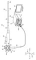
- FIG. 1 is a block diagram of an endoscope system 12 including the endoscope 10 of the present invention.
- the endoscope system 12 includes an endoscope 10, an endoscope processor device 14, and a display 18.
- the endoscope 10 is a lateral endoscope used as, for example, a duodenal endoscope.
- the endoscope 10 includes an operation unit 22 provided with an standing operation lever 20 and an insertion unit 24 connected to the operation unit 22 and inserted into the subject.
- the standing operation lever 20 corresponds to the operation member of the present invention.
- the insertion portion 24 is inserted into the subject via the oral cavity, and further inserted from the esophagus to the duodenum via the stomach.
- treatment such as a predetermined examination or treatment of the duodenum is performed using a treatment tool (not shown, the same applies hereinafter) inserted into the insertion portion 24.
- the treatment tool include biopsy forceps having a cup capable of collecting biological tissue at the tip thereof, an EST (Endoscopic Sphincterotomy) knife, a contrast tube, and the like.
- the insertion portion 24 has a long axis direction Ax (corresponding to the longitudinal axis of the present invention) from the proximal end side to the distal end side, and the soft portion 26 and the curved portion 28 are sequentially arranged from the proximal end side toward the distal end side.
- the tip portion 30 of the insertion portion is provided. The detailed configuration of the insertion portion tip portion 30 will be described later, but first, a schematic configuration of the insertion portion tip portion 30 will be described.
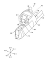
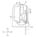
- FIG. 2 is a perspective view of the tip portion 30 of the insertion portion.
- FIG. 3 is a top view of the insertion portion tip portion 30.
- the insertion portion tip portion 30 includes a tip portion main body 32 and a cap 34 detachably attached to the tip portion main body 32.
- an upright stand accommodating space 66 is formed by the tip portion main body 32 and the cap 34.
- the cap 34 is rotatably provided with a treatment tool standing table 36 having a treatment tool guide surface 36a.
- the treatment tool standing table 36 is rotatable between the lying position and the standing position in the standing table accommodating space 66. Note that FIGS. 2 and 3 show a state in which the treatment tool standing table 36 is displaced to the standing position.
- contents arranged inside the insertion portion 24 are connected or inserted into the insertion portion tip portion 30.
- contents include a treatment tool channel 37 (see FIG. 12), an operation wire 38 and a wire channel 40, an air supply / water supply tube 42, and a cable insertion channel 44.
- the treatment tool tip portion (not shown, the same applies hereinafter), which is the tip portion of the treatment tool, is connected to the treatment tool outlet 60 (see FIG. 4) formed in the tip portion main body 32.
- the operation wire 38 is integrally molded with the treatment tool standing table 36, and by rotating the treatment tool standing table 36, the lead-out direction of the treatment tool tip portion led out from the tip portion main body 32 is changed.
- the operation wire 38 is inserted through the wire channel 40.
- the wire channel 40 is not shown as appropriate.
- the air supply / water supply tube 42 supplies the air or water supplied from the operation unit 22 to the air supply / water supply nozzle 58 of the tip main body 32.
- the cable insertion channel 44 includes a light guide that guides the illumination light supplied from the light source device 15 (see FIG. 1) described later to the illumination window 74 of the tip main body 32, and an image not shown in the observation window 76. The signal cable etc. of the part is inserted.
- the X direction including the X (+) direction and the X (-) direction corresponds to the first direction of the present invention.
- the Y direction including the Y (+) direction and the Y ( ⁇ ) direction is parallel to the major axis direction Ax of the insertion portion 24.
- the Z direction including the Z (+) direction and the Z ( ⁇ ) direction corresponds to the second direction perpendicular to both the longitudinal axis and the first direction of the present invention.
- the flexible portion 26 includes a spiral tube (not shown) formed by spirally winding a thin metal strip having elasticity, and a cylinder coated on the outside of the spiral tube and knitted with a metal wire. It has a reticulated body (not shown) and an outer skin (not shown) coated on the outer peripheral surface of the reticulated body and formed of a resin.
- the curved portion 28 includes a structure in which a plurality of angle rings (not shown) are rotatably connected to each other, a tubular metal wire network covering the outer periphery of the structure, and an outer peripheral surface of the mesh. It comprises a rubber hull to cover. For example, four angle wires (not shown) are arranged from the curved portion 28 to the pair of angle knobs 62 of the operation portion 22 described later.
- the operation unit 22 is configured to have a substantially cylindrical shape as a whole.
- the operation unit 22 has an operation unit main body 46 and a grip portion 48 connected to the operation unit main body 46.
- a base end portion (soft portion 26) of the insertion portion 24 is provided on the tip end side of the grip portion 48 via the breakage prevention pipe 50.
- the grip portion 48 is gripped by the operator when the endoscope 10 is operated.
- the grip portion 48 is provided with a treatment tool introduction port 64 for introducing the treatment tool.
- the treatment tool introduced from the treatment tool introduction port 64 is led out to the outside from the treatment tool outlet 60 (see FIG. 4) via the treatment tool channel 37 (see FIG. 12).
- the base end portion of the universal cable 52 is connected to the operation unit main body 46.
- a connector device 54 is provided at the tip of the universal cable 52.
- the connector device 54 is connected to the endoscope processor device 14.
- the endoscope processor device 14 includes a light source device 15 and an image processing device 16.
- the light source device 15 includes a processor-side connector 15A to which the connector device 54 is connected. Further, a display 18 for displaying an image processed by the image processing device 16 is connected to the image processing device 16.
- the connector device 54 and the processor-side connector 15A transmit illumination light, electric power, an image pickup signal, and the like between the endoscope 10 and the endoscope processor device 14 in a non-contact manner (wired transmission is also possible).
- the illumination light from the light source device 15 is emitted from the illumination window 74 (see FIG. 2) provided in the tip main body 32 via the light guide (optical fiber cable, not shown).
- the image pickup signal of the image captured by the photographing unit (not shown) in the observation window 76 is displayed as an image on the display 18 after being image-processed by the image processing device 16.
- the operation unit main body 46 is provided with an air supply / water supply button 57, a suction button 59, a pair of angle knobs 62, and an standing operation lever 20.
- the air supply / water supply button 57 is a button that can be pressed in two stages, and is connected to the air supply / water supply tube 42 and the air supply / water supply source (not shown).
- air is ejected from the air supply / water supply source through the air supply / water supply tube 42 and the air supply / water supply nozzle 58.
- water is ejected from the air supply / water supply source through the air supply / water supply tube 42 and from the air supply / water supply nozzle 58.
- the suction button 59 is connected to the treatment tool channel 37 (see FIG. 12) and a negative pressure source (not shown). When the suction button 59 is pressed, air is sucked from the treatment tool outlet 60 (see FIG. 4) via the treatment tool channel 37 by a negative pressure source. As a result, body fluid such as blood can be sucked from the treatment tool outlet 60.
- the pair of angle knobs 62 are rotatably provided coaxially on the operation unit main body 46.
- the pair of angle knobs 62 are connected to a base end portion on the opposite side of the tip end portion of each angle wire (not shown) connected to the curved portion 28.
- the curved portion 28 is curved up, down, left and right by pushing and pulling each angle wire by each rotation operation of the pair of angle knobs 62.
- the standing operation lever 20 is rotatably provided coaxially with the pair of angle knobs 62 in the operation unit main body 46, and is rotated by the operator who grips the grip portion 48.
- the upright operation lever 20 is connected to a base end portion on the opposite side of the tip end portion of the operation wire 38 integrally molded with the treatment tool upright base 36 via a link mechanism (not shown).
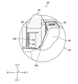
- the operation wire 38 is pushed and pulled by the rotation operation of the standing operation lever 20, and the posture of the treatment tool standing table 36 is displaced between the lying position and the standing position (see FIG. 12).
- the insertion portion tip portion 30 includes a tip portion main body 32, a cap 34 detachably attached to the tip portion main body 32, and a treatment tool standing table 36 integrally molded with the operation wire 38. It is composed of a cap 34 and.
- FIG. 4 is a perspective view of the tip main body 32. As shown in FIG. 4 and the above-mentioned FIGS. 2 and 3, the tip main body 32 is formed in a substantially L shape when viewed from the Z (+) direction side, and the base end wall portion 65 and the first. A wall portion 68 is provided.
- a first wall portion 68 and an air supply / water supply nozzle 58 are provided on the tip surface side of the tip portion main body 32 on the Y (+) direction side. Further, on the base end surface side of the tip main body 32 on the Y (-) direction side, the above-mentioned treatment tool channel 37 (see FIG. 12), the wire channel 40, the air supply / water supply tube 42, and the cable insertion channel 44 Is connected. Further, the tip body 32 is formed with various through holes penetrating the tip body 32 in the Y direction, for example, a treatment tool outlet 60, a wire insertion hole 61, and the like.
- the treatment tool outlet 60 is open in the base end wall portion 65.
- the treatment tool outlet 60 is open in the standing table accommodating space 66 described later, and the treatment tool channel 37 described above is connected to the treatment tool outlet 60.
- the treatment tool is led out from the treatment tool outlet 60 via the standing table accommodating space 66 (treatment tool standing table 36).
- the wire insertion hole 61 is formed at a position displaced on the X (+) direction side and the Z (+) direction side with respect to the treatment tool outlet 60, and the operation wire 38 described above is inserted.
- the first wall portion 68 is located on the tip end surface side of the base end wall portion 65 on the X ( ⁇ ) direction side perpendicular to the longitudinal axis (major axis direction Ax, Y direction) of the tip portion main body 32 with respect to the treatment tool outlet 60. It is provided at the position of, and has a shape extending in the Y (+) direction side, which is the tip end side of the tip portion main body 32.
- the X ( ⁇ ) direction side is the direction perpendicular to the longitudinal axis (major axis direction Ax) of the tip main body 32, and corresponds to the one-way side in the first direction of the present invention.
- the first wall portion 68 forms an upright stand accommodating space 66 for accommodating the treatment tool upright stand 36 (either complete accommodation or partial accommodation is possible) with the cap 34 described later. Further, an illumination window 74 and an observation window 76 are arranged adjacent to each other in the Y direction on the upper surface of the first wall portion 68 on the Z (+) direction side.
- the emission end of the light guide described above is arranged inside the lighting window 74.
- the open side of the standing table accommodation space 66 that is, the Z (+) direction side of the standing table accommodation space 66 can be illuminated by the illumination window 74.
- An imaging unit (not shown) is provided inside the observation window 76.
- the photographing unit photographs a subject existing on the Z (+) direction side of the standing table accommodation space 66 through the observation window 76.
- This photographing unit includes, for example, a photographing optical system (not shown) and a CMOS (complementary metal oxide semiconductor) type or CCD (charge coupled device) type image pickup element (not shown).
- the image pickup signal of the subject output from the image pickup element is input to the image processing device 16 via the signal cable (not shown), the connector device 54, and the processor side connector 15A. As a result, the image of the subject is displayed on the display 18.
- the air supply / water supply nozzle 58 is provided at a position on the tip end surface side of the tip portion main body 32 and on the Z (+) direction side of the first wall portion 68, and injects air and water toward the observation window 76.
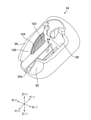
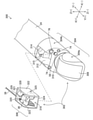
- FIG. 5 is a perspective view of the cap 34 to which the treatment tool standing table 36 and the operation wire 38 are attached.
- FIG. 6 is a top view of the cap 34 to which the treatment tool standing table 36 and the operation wire 38 are attached.
- FIG. 7 is a perspective view of the cap 34 from which the treatment tool standing table 36 and the operation wire 38 are removed.
- the cap 34, the treatment tool standing table 36, and the operation wire 38 have tips before the use of the endoscope 10 (treatment, inspection, etc.). It is a disposable product (replacement product) that is attached to the main body 32 and is removed from the front main body 32 and discarded after the use is completed.
- the cap 34, the treatment tool standing table 36, and the operation wire 38 constitute the treatment tool standing mechanism of the present invention.
- the cap 34 has a substantially bottomed tubular shape and is detachably attached to the tip body 32.
- This cap 34 corresponds to the standing table accommodating space forming member of the present invention, and when attached to the tip main body 32, the treatment tool standing table 36 together with the base end wall portion 65 and the first wall portion 68.
- the upright stand accommodating space 66 (see FIGS. 2 and 3) for accommodating the above is formed.
- the cap 34 is formed with a first opening window 80, a cap tip portion 82, an upright stand holding portion 84, and a second wall portion 86.
- the first opening window 80 is the upper surface (illumination window) of the standing table accommodating space 66 and the first wall portion 68 when the insertion portion tip portion 30 is viewed from the position on the Z (+) direction side of the insertion portion tip portion 30. 74, observation window 76, etc.) are exposed. This makes it possible to derive the treatment tool from the standing table accommodation space 66 toward the Z (+) direction, and to illuminate and photograph the subject as described above.
- the cap tip 82 covers the tip surface of the tip body 32 on the Y (+) direction side.
- the second cap accommodation space 66 is exposed to the cap tip 82 when viewed from the tip side of the cap 34 (when the cap 34 is viewed from the position on the Y (+) direction side of the cap 34).
- An opening window 82a (corresponding to the opening window of the present invention, see FIG. 13) is formed.
- the second opening window 82a has a shape suitable for passing a finger or a jig when the cap 34 is attached to or detached from the tip main body 32, particularly when the cap 34 is removed. As a result, the cap 34 can be easily attached and detached.
- the upright stand holding portion 84 (see FIG. 7) is formed at the bottom of the inner peripheral surface of the cap 34 defining the bottom surface of the upright stand accommodation space 66, and is formed via a rotation shaft 88 (see FIG. 12) as a treatment tool.
- the standing table 36 is rotatably held between the lying position and the standing position.
- the second wall portion 86 is located at a position on the X (+) direction side with respect to the treatment tool outlet 60 and at a position facing the first wall portion 68 when the cap 34 is attached to the tip portion main body 32. It is arranged and has a shape extending in the Y (+) direction like the first wall portion 68. In this case, the X (+) direction side corresponds to the other direction side of the first direction of the present invention.
- the width of the standing table accommodation space 66 in the X direction is defined by the second wall portion 86 and the first wall portion 68.
- the second wall portion 86 is formed with a first wall surface 100, a second wall surface 102, and a stepped surface 104, which will be described in detail later, on the side facing the first wall portion 68 and the treatment tool standing table 36.
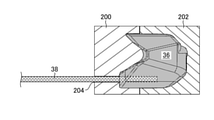
- FIG. 8 is an explanatory diagram for explaining a method of forming the treatment tool standing table 36 and the operation wire 38.
- the treatment tool standing table 36 and the operation wire 38 are insert molded bodies integrated by a known insert molding method.
- first mold 200 and second mold 202 that form a cavity (mold) corresponding to the treatment tool standing table 36 in a superposed state are prepared, and the first mold 200 and the second mold 200 and the second mold 202 are prepared. Overlay the molds 202.
- the tip of the operation wire 38 is placed inside the cavity through the through hole 204 provided in the first mold 200.
- the material of the treatment tool standing table 36 is injected and filled in the cavity, and then cooled to form an insert molded body of the treatment tool standing table 36 and the operation wire 38.
- the insert molding method of the treatment tool standing table 36 and the operation wire 38 is not limited to the above-mentioned method, and various known insert molding methods may be adopted.
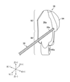
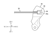
- FIG. 9 is a perspective view of the treatment tool standing table 36 and the operation wire 38.
- the treatment tool standing table 36 is attached to the tip main body 32 together with the cap 34, the treatment tool facing the treatment tool outlet 60
- the guide surface 36a is formed.
- the treatment tool guide surface 36a changes the traveling direction of the tip of the treatment tool led out from the treatment tool outlet 60 into the standing table accommodation space 66 toward the first opening window 80 (outside of the standing table accommodation space 66). do.
- the treatment tool standing table 36 includes a standing table main body 90, a standing table tip 92, and a wire connecting portion 94.
- the standing table main body 90 has an insertion hole 90a through which a rotating shaft 88 (see FIG. 12) is inserted at its base end, and is rotatably held by the standing table holding portion 84 via the rotating shaft 88. Will be done.
- the upright stand tip portion 92 is provided on the tip end side (the direction opposite to the direction toward the insertion hole 90a and the rotation shaft 88) of the upright stand main body 90.
- the wire connecting portion 94 is provided on the side surface of the tip portion 92 of the standing table on the X (+) direction side, has a shape protruding from this side surface on the X (+) direction side, and is at least from the standing table main body portion 90. Also has a shape protruding in the X (+) direction.
- a wire tip 38a which is the tip of the operation wire 38, is connected (held) to the wire connecting portion 94.
- the wire tip 38a is connected to the wire connecting portion 94 and is exposed in the standing table accommodating space 66 according to the posture of the treatment tool standing table 36.
- the wire tip 38a is X (+) more than the standing base body 90 when the insertion tip 30 is viewed from the position on the Z (+) direction side (corresponding to the second direction) of the insertion tip 30. ) It is located on the direction side.
- a structure (first wall surface 100, second wall surface 102, and stepped surface 104) is formed in the second wall portion 86 of the cap 34 to fill the above-mentioned gap.
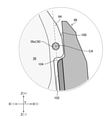
- FIG. 10 is a cross-sectional view of the insertion portion tip portion 30 along the XX line in FIG.
- FIG. 11 is an enlarged view of a part of the region in FIG.
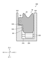
- FIG. 12 is a cross-sectional view of the insertion portion tip portion 30 along the line XII-XII in FIG.
- FIG. 13 is a front view of the insertion portion tip 30 as viewed from the position on the Y (+) direction side of the insertion portion tip 30.
- the first wall surface 100 is a wire connecting portion 94 (wire tip portion 38a) of the treatment tool standing table 36 that rotates about the rotation shaft 88 in the second wall portion 86. It is formed at a position facing the. That is, the first wall surface 100 is on the X (+) direction side of the wire connecting portion 94 and the wire tip portion 38a when the insertion portion tip portion 30 is viewed from the position on the Z (+) direction side of the insertion portion tip portion 30. It is formed at the position of.
- the width (thickness) of the standing base tip portion 92 including the wire connecting portion 94 in the X direction. can be increased. Therefore, it is possible to improve the fluidity of the material at the time of insert molding of the treatment tool standing table 36 and the like shown in FIG. 8 described above.
- the first wall surface 100 is a wire connecting portion in which at least a part thereof rotates about the rotation shaft 88 when the second wall portion 86 is viewed from the position on the X ( ⁇ ) direction side of the second wall portion 86. It has a shape along the trajectory of 94.
- the first wall surface 100 of the present embodiment has a region having a shape along the locus described above and an extension extending from the region toward the tip end side [Y (+) direction side] of the insertion portion tip portion 30.
- the shape of the first wall surface 100 is not particularly limited as long as it includes a region, but at least the former region is included.
- the second wall surface 102 is located in the second wall portion 86 at a position facing the upright base main body 90 of the treatment tool upright base 36 that rotates about the rotation shaft 88, and is X more than the first wall surface 100. It is formed at the position on the (-) direction side.
- the second wall surface 102 is an upright base main body 90 that rotates about a rotation shaft 88 when the second wall 86 is viewed from a position on the X ( ⁇ ) direction side of the second wall 86. It has a shape along the trajectory of.
- the second wall surface 102 has a wire tip portion 38a (wire) in the X direction when the insertion portion tip portion 30 is viewed from a position on the Z (+) direction side (corresponding to the second direction) of the insertion portion tip portion 30. It overlaps with at least a part of the connection portion 94). Therefore, the second wall surface 102 is formed at a position that fills the gap on the Z ( ⁇ ) direction side of the wire tip portion 38a. This makes it possible to prevent the tip of the treatment tool from slipping into the gap.
- the second wall surface 102 is the Z (+) of the tip 30 of the insertion portion.
- the insertion portion tip 30 is viewed from the position on the direction side, it is formed at a position (including the position of the central axis CA) on the X (-) direction side of the central axis CA (see FIG. 11) of the wire tip 38a. It is preferable that it is.
- the position of the second wall surface 102 is set between the central axis CA and the upright stand main body 90 in the X direction. Adjust to the appropriate position between.
- the amount of steps (height difference) in the X direction between the first wall surface 100 and the second wall surface 102 is, for example, 1 to 2 mm.
- the step surface 104 is formed between the first wall surface 100 and the second wall surface 102, and is a connecting surface (boundary surface) connecting the first wall surface 100 and the second wall surface 102.
- This stepped surface 104 is a wire that rotates integrally with the wire connecting portion 94 about the rotation shaft 88 when the second wall portion 86 is viewed from the position on the X ( ⁇ ) direction side of the second wall portion 86. It is formed in an arc shape along the locus of the tip portion 38a.
- the wire tip portion 38a is aligned with the step surface 104.
- the stepped surface 104 also functions as a guide surface for the wire tip portion 38a.
- the wire tip 38a may be in sliding contact with the step surface 104, or even if there is a gap between the wire tip 38a and the step surface 104 to the extent that the tip of the treatment tool can be prevented from slipping. good.
- FIG. 14 is an explanatory diagram for explaining the formation of the cap 34, particularly the formation of the stepped surface 104 of the second wall portion 86.
- the illustration of the parts not related to the formation of the stepped surface 104 is omitted as appropriate.
- the cap 34 is formed by using a pair of the first mold 210 and the second mold 212.
- the first mold 210 and the second mold 212 form a cavity (mold) corresponding to the cap 34 in a separable and superposed state.
- the cap 34 is formed by injecting, cooling, and solidifying the material of the cap 34 into the cavity, and then separating the first mold 210 and the second mold 212.
- the first mold 210 and the second mold 212 that can be separated in the Y direction as shown in FIG. 14 are used.
- a second opening window 82a (see FIG. 13) that exposes the standing table accommodating space 66 is formed in the cap tip portion 82. Therefore, after the material of the cap 34 is solidified, the mold surface 210a corresponding to the stepped surface 104 is separated from the stepped surface 104 in the Y (+) direction in the first mold 210 through the second opening window 82a. Can be done.
- the wire tip is filled with the second wall surface 102 and the stepped surface 104 formed on the second wall 86 of the cap 34 in the Z ( ⁇ ) direction side of the wire tip 38a. It is possible to prevent the tip of the treatment tool from slipping into the position of the portion 38a on the Z ( ⁇ ) direction side. Further, by providing the second wall portion 86 (the second wall surface 102 and the stepped surface 104) on the disposable cap 34, it is not necessary to provide the tip main body 32 with a configuration corresponding to the second wall portion 86, so that the cap It is prevented that the accessibility of the cleaning brush to the tip body 32 after the removal of the 34 is deteriorated.
- FIG. 15 is a side view of the treatment tool standing table 36 of another embodiment.
- the treatment tool stand 36 and the operation wire 38 are integrated by insert molding, but as shown in FIG. 15, the treatment tool stand 36 and the operation wire 38 may be formed separately.
- a wire attachment portion 96 to which the wire tip portion 38a can be attached is formed on the wire connection portion 94 of the treatment tool standing table 36.
- the wire attachment portion 96 include an engagement groove with which the wire tip portion 38a engages, but the shape and configuration thereof are not particularly limited as long as the wire tip portion 38a can be attached.
- the standing portion including the wire connecting portion 94 is increased as the distance in the X direction between the first wall surface 100 and the wire connecting portion 94 and the wire tip portion 38a increases. Since the width (thickness) of the table tip portion 92 in the X direction can be increased, the rigidity of the treatment tool standing table 36 can be ensured.
- the second opening window 82a is formed in the cap tip portion 82, but the cap 34 can be formed by a mold of the upper and lower separation type, or the cap 34 can be formed by a method other than the mold (for example, a 3D printer). Etc.), the second opening window 82a may not be formed on the cap tip 82.
- the cap 34, the treatment tool standing table 36, and the operation wire 38 are disposable products, but they may be used a plurality of times by cleaning and disinfecting treatment.
- the wire connecting portion 94 of the treatment tool standing table 36 has a shape protruding in the X (+) direction from the standing table main body 90, but the wire connecting portion 94 is the standing table tip portion 92. May be formed in a substantially planar shape on the side surface on the X (+) direction side of the above (see Patent Documents 3 and 4 above). Even in this case, the tip of the treatment tool slips into the Z (-) direction side of the wire tip 38a located on the X (+) direction side of the standing table main body 90 due to the second wall surface 102 and the stepped surface 104. Is prevented.
- a side-viewing endoscope (duodenal endoscope) has been described as an example of the endoscope 10, but various types of endoscopes such as an ultrasonic endoscope that changes the posture of the treatment tool standing table 36 by a wire traction method are used.
- the present invention can be applied to an endoscope and its treatment tool standing mechanism.
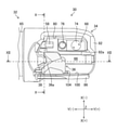
- FIG. 16 is an exploded perspective view of the tip portion 302 of the insertion portion of the ultrasonic endoscope 300.
- the insertion portion tip portion 302 includes a tip portion main body 304 (also referred to as a tip rigid portion) and an upright unit 306 detachably attached to the tip portion main body 304.
- the tip main body 304 includes a transducer mounting portion 304a and a main body base 304b from the Y (+) direction side to the Y (-) direction side.
- An ultrasonic transducer 308 is attached to the transducer mounting portion 304a. Although not shown, a balloon covering the ultrasonic transducer 308 can be detachably attached to the transducer mounting portion 304a.
- the ultrasonic transducer 308 is a convex type having an ultrasonic transmission / reception surface in which a large number of ultrasonic transducers that transmit and receive ultrasonic waves are arranged. Since the structure and function of the ultrasonic transducer 308 are known techniques, specific description thereof will be omitted here.
- the main body base 304b is provided with an inclined surface 310 from the Y (+) direction side to the Y (-) direction side, and an upright unit mounting hole 312.
- the inclined surface 310 is gradually inclined downward from the Y ( ⁇ ) direction side toward the Y (+) direction side when viewed from the X direction side.
- the inclined surface 310 is provided with the illumination window 74, the observation window 76, and the air supply / water supply nozzle 58 described above.
- the standing unit mounting hole 312 is a rectangular hole opened on the surface of the main body base 304b on the Z (+) direction side.
- An upright unit 306, which will be described later, is detachably attached to the upright unit mounting hole 312.
- the wall surface defining the Y ( ⁇ ) direction side of the standing unit mounting hole 312 has a treatment tool insertion port connected to the above-mentioned treatment tool channel 37.
- a 314 and a wire insertion hole 315 connected to the above-mentioned wire channel 40 are formed.
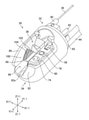
- FIG. 17 is an enlarged perspective view of the standing unit 306.
- the standing unit 306 corresponds to the standing table accommodating space forming member of the present invention, has an upright table accommodating space 318, and has the above-mentioned treatment tool upright table 36. Is rotatably held.
- the upright unit 306 is detachably mounted in the upright unit mounting hole 312.
- the standing unit 306, the treatment tool standing table 36, and the operation wire 38 constitute the treatment tool standing mechanism of the present invention.
- the standing unit 306, the treatment tool standing table 36, and the operation wire 38 are disposable products (replacement products) that are removed from the tip main body 304 and discarded after the use of the ultrasonic endoscope 300 is completed.
- the standing unit 306 has an opening 320, a base end wall portion 321, a first wall portion 322, a second wall portion 323, a bottom wall portion 324, and a rotation shaft 325.
- the base end wall portion 321 and the first wall portion 322, the second wall portion 323, and the bottom wall portion 324 form an upright stand accommodating space 318.
- the opening 320 exposes the standing table accommodating space 318 when the standing unit 306 (tip body 304) is viewed from the Z (+) direction side thereof. This makes it possible to derive the treatment tool from the standing table accommodating space 318 toward the Z (+) direction.
- the base end wall portion 321 defines the Y ( ⁇ ) direction side of the standing table accommodating space 318, and the treatment tool outlet 328 and the wire insertion hole 329 are open.
- the treatment tool outlet 328 is connected to the treatment tool channel 37 via the treatment tool insertion port 314 when the standing unit 306 is mounted in the standing unit mounting hole 312. As a result, the treatment tool is led out from the treatment tool outlet 328 through the standing table accommodating space 318 (treatment tool standing table 36). Further, the wire insertion hole 329 is connected to the wire channel 40 via the wire insertion hole 315 when the upright unit 306 is mounted in the upright unit mounting hole 312. As a result, the operation wire 38 can be inserted from the wire insertion hole 329 through the wire insertion hole 315 into the wire channel 40.
- the first wall portion 322 is provided at a position on the X ( ⁇ ) direction side with respect to the treatment tool outlet 328 on the tip end surface side of the base end wall portion 321 and has a shape extending in the Y (+) direction side. Have. The first wall portion 322 defines the X ( ⁇ ) direction side of the standing table accommodating space 318.
- the second wall portion 323 is provided at a position on the X (+) direction side with respect to the treatment tool outlet 328 on the tip end surface side of the base end wall portion 321 and has a shape extending in the Y (+) direction. Have.
- the second wall portion 323 defines the X (+) direction side of the standing table accommodating space 318.
- the width of the standing table accommodating space 318 in the X direction is defined by the first wall portion 322 and the second wall portion 323.
- the first wall surface 100 and the second wall surface 102 similar to those in the above embodiment (see FIG. 7) , And the stepped surface 104 is formed.
- the bottom wall portion 324 covers the standing table accommodating space 318 in the Z (-) direction of both the first wall portion 322 and the second wall portion 323. It is provided between the ends on the side.
- the bottom wall portion 324 defines the Z ( ⁇ ) direction side of the upright stand accommodating space 318.
- the rotary shaft 325 is basically the same as the rotary shaft 88 of the above embodiment, and one end thereof is attached to the first wall portion 322 and the other end is attached to the second wall portion 323.
- the rotating shaft 325 rotatably holds the treatment tool standing table 36 between the lying position and the standing position (see FIG. 12).
- FIG. 18 is a cross-sectional view taken along the line XVIII-XVIII in FIG. It should be noted that FIG. 18 simply illustrates the treatment tool standing table 36. As shown in FIG. 18, the treatment tool standing table 36 includes the standing table main body 90, the standing table tip 92, and the wire connecting portion 94 as described above.
- the second wall surface 102 is at least a part of the wire connecting portion 94 (wire tip portion 38a, see FIG. 9) in the X direction when the insertion portion tip portion 302 (standing unit 306) is viewed from the Z (+) direction side. It overlaps with. Therefore, the second wall surface 102 prevents the tip of the treatment tool from slipping into the gap of the wire tip 38a on the Z ( ⁇ ) direction side, as in the above embodiment.
- the stepped surface 104 together with the second wall surface 102, prevents the tip of the treatment tool from slipping into the gap on the Z ( ⁇ ) direction side of the wire tip 38a. Further, the stepped surface 104 functions as a guide surface for the wire tip portion 38a when the treatment tool standing table 36 rotates between the inverted position and the standing position.
- the tip portion of the treatment tool slips into the position of the wire tip portion 38a on the Z (-) direction side. Can be prevented. Further, by providing the second wall portion 323 (the second wall surface 102 and the stepped surface 104) on the disposable type upright unit 306, it is not necessary to provide the tip portion main body 304 with a configuration corresponding to the second wall portion 323. It is possible to prevent the cleaning brush from being inaccessible to the tip main body 304 after the erecting unit 306 is removed.
Landscapes
- Health & Medical Sciences (AREA)
- Life Sciences & Earth Sciences (AREA)
- Surgery (AREA)
- Physics & Mathematics (AREA)
- Engineering & Computer Science (AREA)
- General Health & Medical Sciences (AREA)
- Animal Behavior & Ethology (AREA)
- Radiology & Medical Imaging (AREA)
- Veterinary Medicine (AREA)
- Nuclear Medicine, Radiotherapy & Molecular Imaging (AREA)
- Biomedical Technology (AREA)
- Heart & Thoracic Surgery (AREA)
- Medical Informatics (AREA)
- Molecular Biology (AREA)
- Pathology (AREA)
- Biophysics (AREA)
- Public Health (AREA)
- Optics & Photonics (AREA)
- Mechanical Engineering (AREA)
- Astronomy & Astrophysics (AREA)
- General Physics & Mathematics (AREA)
- Endoscopes (AREA)
Priority Applications (3)
| Application Number | Priority Date | Filing Date | Title |
|---|---|---|---|
| JP2022536340A JP7763171B2 (ja) | 2020-07-17 | 2021-07-12 | 内視鏡及び処置具起立機構 |
| CN202180045165.9A CN115884706A (zh) | 2020-07-17 | 2021-07-12 | 内窥镜及处置器具竖立机构 |
| US18/069,437 US20230122213A1 (en) | 2020-07-17 | 2022-12-21 | Endoscope and treatment tool elevating mechanism |
Applications Claiming Priority (2)
| Application Number | Priority Date | Filing Date | Title |
|---|---|---|---|
| JP2020122665 | 2020-07-17 | ||
| JP2020-122665 | 2020-07-17 |
Related Child Applications (1)
| Application Number | Title | Priority Date | Filing Date |
|---|---|---|---|
| US18/069,437 Continuation US20230122213A1 (en) | 2020-07-17 | 2022-12-21 | Endoscope and treatment tool elevating mechanism |
Publications (1)
| Publication Number | Publication Date |
|---|---|
| WO2022014524A1 true WO2022014524A1 (ja) | 2022-01-20 |
Family
ID=79555486
Family Applications (1)
| Application Number | Title | Priority Date | Filing Date |
|---|---|---|---|
| PCT/JP2021/026098 Ceased WO2022014524A1 (ja) | 2020-07-17 | 2021-07-12 | 内視鏡及び処置具起立機構 |
Country Status (4)
| Country | Link |
|---|---|
| US (1) | US20230122213A1 (enExample) |
| JP (1) | JP7763171B2 (enExample) |
| CN (1) | CN115884706A (enExample) |
| WO (1) | WO2022014524A1 (enExample) |
Families Citing this family (2)
| Publication number | Priority date | Publication date | Assignee | Title |
|---|---|---|---|---|
| CN110179431B (zh) * | 2019-06-24 | 2025-08-22 | 深圳开立生物医疗科技股份有限公司 | 内窥镜抬钳器、内窥镜头端和十二指肠镜系统 |
| EP4292511A1 (en) * | 2022-06-17 | 2023-12-20 | Ambu A/S | An endoscope |
Citations (5)
| Publication number | Priority date | Publication date | Assignee | Title |
|---|---|---|---|---|
| JPH0390126A (ja) * | 1990-07-31 | 1991-04-16 | Olympus Optical Co Ltd | 内視鏡 |
| JPH07194513A (ja) * | 1993-12-28 | 1995-08-01 | Olympus Optical Co Ltd | 内視鏡用カバー部材 |
| JPH11299728A (ja) * | 1998-04-24 | 1999-11-02 | Fuji Photo Optical Co Ltd | 内視鏡の処置具起立装置 |
| JP2007215634A (ja) * | 2006-02-15 | 2007-08-30 | Fujinon Corp | 体腔内検査装置 |
| WO2016027574A1 (ja) * | 2014-08-19 | 2016-02-25 | オリンパス株式会社 | 伝達機構と起上装置と挿入機器 |
Family Cites Families (3)
| Publication number | Priority date | Publication date | Assignee | Title |
|---|---|---|---|---|
| JPH08154890A (ja) * | 1994-12-01 | 1996-06-18 | Olympus Optical Co Ltd | 内視鏡 |
| EP3603529B1 (en) * | 2017-03-31 | 2023-10-25 | FUJIFILM Corporation | Ultrasonic endoscope |
| WO2019163401A1 (ja) * | 2018-02-23 | 2019-08-29 | 富士フイルム株式会社 | 内視鏡 |
-
2021
- 2021-07-12 WO PCT/JP2021/026098 patent/WO2022014524A1/ja not_active Ceased
- 2021-07-12 JP JP2022536340A patent/JP7763171B2/ja active Active
- 2021-07-12 CN CN202180045165.9A patent/CN115884706A/zh active Pending
-
2022
- 2022-12-21 US US18/069,437 patent/US20230122213A1/en active Pending
Patent Citations (5)
| Publication number | Priority date | Publication date | Assignee | Title |
|---|---|---|---|---|
| JPH0390126A (ja) * | 1990-07-31 | 1991-04-16 | Olympus Optical Co Ltd | 内視鏡 |
| JPH07194513A (ja) * | 1993-12-28 | 1995-08-01 | Olympus Optical Co Ltd | 内視鏡用カバー部材 |
| JPH11299728A (ja) * | 1998-04-24 | 1999-11-02 | Fuji Photo Optical Co Ltd | 内視鏡の処置具起立装置 |
| JP2007215634A (ja) * | 2006-02-15 | 2007-08-30 | Fujinon Corp | 体腔内検査装置 |
| WO2016027574A1 (ja) * | 2014-08-19 | 2016-02-25 | オリンパス株式会社 | 伝達機構と起上装置と挿入機器 |
Also Published As
| Publication number | Publication date |
|---|---|
| JPWO2022014524A1 (enExample) | 2022-01-20 |
| CN115884706A (zh) | 2023-03-31 |
| US20230122213A1 (en) | 2023-04-20 |
| JP7763171B2 (ja) | 2025-10-31 |
Similar Documents
| Publication | Publication Date | Title |
|---|---|---|
| JP6860702B2 (ja) | 内視鏡 | |
| JP5030514B2 (ja) | 内視鏡及び内視鏡システム | |
| JP7114618B2 (ja) | 内視鏡 | |
| JP5489418B2 (ja) | 超音波プローブ用フード及び超音波プローブ | |
| JPWO2019065580A1 (ja) | 内視鏡 | |
| US20180160885A1 (en) | Endoscopy based medical devices, methods, and innovations | |
| JPWO2018100823A1 (ja) | 内視鏡及び内視鏡のワイヤ取り付け方法並びに内視鏡のワイヤ取り外し方法 | |
| US20070059956A1 (en) | Insertion apparatus | |
| JP6854963B2 (ja) | 内視鏡 | |
| WO2022014524A1 (ja) | 内視鏡及び処置具起立機構 | |
| JP7270745B2 (ja) | 内視鏡 | |
| JP2024028539A (ja) | 起立台の成形方法及び内視鏡 | |
| JP7076561B2 (ja) | オーバーチューブ | |
| WO2022191108A1 (ja) | 内視鏡および先端キャップ | |
| US12185914B2 (en) | Distal end cap detachment jig and endoscope | |
| JP7097860B2 (ja) | 内視鏡 | |
| JP2000185042A (ja) | 処置用超音波内視鏡の先端部 | |
| JP2020137946A (ja) | 内視鏡 | |
| US20180153387A1 (en) | Lubricant applicator device and method of an insertion tube of an endoscope | |
| JP2025188239A (ja) | 起立台の成形方法及び内視鏡 | |
| JP2024033891A (ja) | 内視鏡および先端キャップ | |
| JP6745896B2 (ja) | 起上台洗浄用ブラシ、内視鏡の起上台洗浄方法、及び内視鏡セット | |
| JP2006087520A (ja) | 内視鏡 | |
| JP2021049269A (ja) | 内視鏡 | |
| CN115885206A (zh) | 内窥镜结构部的成型方法及内窥镜 |
Legal Events
| Date | Code | Title | Description |
|---|---|---|---|
| 121 | Ep: the epo has been informed by wipo that ep was designated in this application |
Ref document number: 21841825 Country of ref document: EP Kind code of ref document: A1 |
|
| ENP | Entry into the national phase |
Ref document number: 2022536340 Country of ref document: JP Kind code of ref document: A |
|
| NENP | Non-entry into the national phase |
Ref country code: DE |
|
| 122 | Ep: pct application non-entry in european phase |
Ref document number: 21841825 Country of ref document: EP Kind code of ref document: A1 |