WO2022014464A1 - ステータ - Google Patents
ステータ Download PDFInfo
- Publication number
- WO2022014464A1 WO2022014464A1 PCT/JP2021/025810 JP2021025810W WO2022014464A1 WO 2022014464 A1 WO2022014464 A1 WO 2022014464A1 JP 2021025810 W JP2021025810 W JP 2021025810W WO 2022014464 A1 WO2022014464 A1 WO 2022014464A1
- Authority
- WO
- WIPO (PCT)
- Prior art keywords
- winding
- coil
- terminal
- stator
- teeth
- Prior art date
- Legal status (The legal status is an assumption and is not a legal conclusion. Google has not performed a legal analysis and makes no representation as to the accuracy of the status listed.)
- Ceased
Links
Images





Classifications
-
- H—ELECTRICITY
- H02—GENERATION; CONVERSION OR DISTRIBUTION OF ELECTRIC POWER
- H02K—DYNAMO-ELECTRIC MACHINES
- H02K3/00—Details of windings
- H02K3/04—Windings characterised by the conductor shape, form or construction, e.g. with bar conductors
- H02K3/18—Windings for salient poles
-
- H—ELECTRICITY
- H02—GENERATION; CONVERSION OR DISTRIBUTION OF ELECTRIC POWER
- H02K—DYNAMO-ELECTRIC MACHINES
- H02K3/00—Details of windings
- H02K3/46—Fastening of windings on the stator or rotor structure
- H02K3/52—Fastening salient pole windings or connections thereto
-
- Y—GENERAL TAGGING OF NEW TECHNOLOGICAL DEVELOPMENTS; GENERAL TAGGING OF CROSS-SECTIONAL TECHNOLOGIES SPANNING OVER SEVERAL SECTIONS OF THE IPC; TECHNICAL SUBJECTS COVERED BY FORMER USPC CROSS-REFERENCE ART COLLECTIONS [XRACs] AND DIGESTS
- Y02—TECHNOLOGIES OR APPLICATIONS FOR MITIGATION OR ADAPTATION AGAINST CLIMATE CHANGE
- Y02T—CLIMATE CHANGE MITIGATION TECHNOLOGIES RELATED TO TRANSPORTATION
- Y02T10/00—Road transport of goods or passengers
- Y02T10/60—Other road transportation technologies with climate change mitigation effect
- Y02T10/64—Electric machine technologies in electromobility
Definitions
- This disclosure relates to the stator.
- each winding is wound in series. To. Then, coil terminals are connected to both ends of each winding, and each winding is connected in parallel by a wiring component such as a bus bar connected to the coil terminal.
- An object of the present disclosure is to provide a stator capable of reducing the number of parts and manufacturing man-hours.
- the present disclosure is a stator of an inner rotor type rotary electric machine, which is a stator core having a plurality of teeth, a plurality of windings having a coil wound around the teeth, and a plurality of coil terminals connected to the windings. And prepare.
- the winding has two or more coils between one end and the other end of the winding.
- the plurality of coil terminals are connected to a first coil terminal having a first winding connection connected to one end or the other end of the winding and an intermediate portion between two coils contained in one winding.
- the nozzle winding is carried out by continuously winding two or more teeth between the winding start and the winding end of the winding, and the winding is performed in the middle of the winding.
- a parallel circuit can be constructed by passing the wire through the second coil terminal.
- FIG. 1 is a schematic diagram illustrating a shift-by-wire system to which a rotary actuator with a motor of one embodiment is applied.
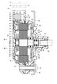
- FIG. 2 is a cross-sectional view of the rotary actuator of FIG.
- FIG. 3 is a view of the stator and control board of FIG. 2 as viewed from the direction of arrow III.
- FIG. 4 is an enlarged view of a main part of the stator of FIG.
- FIG. 5 is a view of the stator of FIG. 4 as viewed from the direction of arrow V.
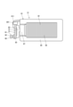
- FIG. 6 is a diagram schematically showing the winding and coil terminals of FIG.
- FIG. 7 is a view of the stator, motor terminal, and sensor terminal of FIG. 2 as viewed from the direction of arrow VII.
- the motor 30 as the inner rotor type rotary electric machine of one embodiment is provided in the rotary actuator (hereinafter, actuator) 10.
- the actuator 10 is fixed to the outer wall of the case 12 of the vehicle transmission 11 and is used as a power source for the shift-by-wire system 13.
- the control device 15 controls the actuator 10 in response to a command signal from the shift operation device 14 to operate the shift range switching mechanism 16 of the transmission 11 to switch the shift range.
- the actuator 10 includes a housing 20, a motor 30, and a speed reducer 40.
- the housing 20 has a cup-shaped front housing 21 and a rear housing 22.
- the front housing 21 and the rear housing 22 are combined with each other and fastened to each other by bolts 23.
- a bottomed cylindrical metal plate 24 is inserted into the front housing 21.
- the rear housing 22 has a tubular protrusion 28 that projects to the opposite side of the front housing 21.
- a bracket 29 is fixed to the outer wall of the rear housing 22.
- the actuator 10 is fixed to the case 12 (see FIG. 1) of the transmission 11 by using the bracket 29.
- the motor 30 has a stator 31 and a rotor 34.
- the stator 31 has a stator core 32 fixed to the metal plate 24 by, for example, press fitting, and a winding 33 provided on the stator core 32.
- the rotor 34 has a rotary shaft 37 rotatably supported around the rotary shaft center AX1 by a motor side bearing 35 and a speed reducer side bearing 36, and a rotor core 38 fitted and fixed to the outside of the rotary shaft 37. ..
- the motor side bearing 35 is provided on the metal plate 24.
- the speed reducer side bearing 36 is provided on the output member 44, which will be described later.
- the speed reducer 40 includes an eccentric shaft 41, a ring gear 42, an eccentric gear 43, an output member 44, and a transmission mechanism 45.
- the eccentric shaft 41 is provided on the eccentric shaft center AX2 that is eccentric with respect to the rotation shaft center AX1, and is integrally formed with the rotation shaft 37.
- the ring gear 42 is provided coaxially with the rotation axis AX1 and is fixed to the rear housing 22.
- the eccentric gear 43 has an external tooth portion 47 that meshes with the internal tooth portion 46 of the ring gear 42, and is supported by a bearing 48 provided on the eccentric shaft 41 so as to be able to move planetarily.
- the planetary motion is a motion that revolves around the rotation axis AX1 while rotating around the eccentric axis AX2. The rotation speed of the eccentric gear 43 during planetary motion is changed with respect to the rotation speed of the rotation shaft 37.
- the output member 44 is provided coaxially with the rotation axis AX1 and is rotatably supported by a bearing 49 provided in the rear housing 22.
- the transmission mechanism 45 is composed of an engaging protrusion 51 formed in the eccentric gear 43 and an engaging hole 52 formed in the output member 44 into which the engaging protrusion 51 is inserted, and is composed of an eccentric axis AX2 of the eccentric gear 43. The rotation around it is transmitted to the output member 44.
- a rotating magnetic field is generated by switching the energizing phase of the winding 33, and the rotor 34 rotates under the magnetic attraction or repulsion force generated by the rotating magnetic field.
- the eccentric shaft 41 rotates around the rotation axis AX1 together with the rotor 34, the eccentric gear 43 makes a planetary motion, and the rotation of the eccentric gear 43 decelerated with respect to the rotation of the rotor 34 is output from the output member 44.
- the stator 31 includes a stator core 32, a plurality of windings 33, an insulator 61 interposed between the stator core 32 and the winding 33, and a plurality of windings 33 connected to the stator core 32. It is provided with a coil terminal 81.
- the stator core 32 is composed of a plurality of metal plates laminated in the axial direction.
- the stator core 32 has an annular yoke 55 fixed to the inner wall of the tubular portion 25 of the front housing 21, and a plurality of teeth 56 formed so as to project radially inward from the yoke 55.
- the insulator 61 includes a yoke insulating portion 62 provided on both ends in the axial direction of the yoke 55 and an inner wall on the inner side in the radial direction, and a portion around the teeth 56 (that is, other than the tip surface of the teeth 56).
- the plurality of windings 33 include a U-phase winding 33u, a V-phase winding 33v, and a W-phase winding 33w.
- winding 33 when each winding is not distinguished, it is simply described as "winding 33".
- the winding 33 has a coil 71 wound around the teeth 56, that is, around the teeth insulating portion 63 of the insulator 61.
- One winding 33 consists of one electric wire and has four coils 71 between one end 72 and the other end 73 thereof.
- a crossover line 74 is provided between the coils 71. That is, one winding 33 is provided across the four teeth 56.
- the U-phase winding 33u has coils 71u11, 71u12, 71u21, and 71u22.
- the V-phase winding 33v has coils 71v11, 71v12, 71v21, 71v22.
- the W-phase winding 33w has coils 71w11, 71w12, 71w21 and 71w22.
- the coils 71u11 and 71u12 from one end 72 to the intermediate 74c and the 71u21 and 71u22 from the intermediate 74c to the other end 73 are arranged in parallel.
- the first coil group and the second coil group are arranged in parallel.
- twelve teeth 56 are provided, and one coil 71 is provided for each tooth 56.
- One winding 33 has a coil 71 for one phase.
- the yoke insulating portion 62 has a protruding locking portion 65 protruding toward the bottom 26 side of the front housing 21.
- the locking portion 65 locks the crossover line 74.
- the locking portion 65 is integrally provided with the insulator 61.
- the actuator 10 includes a magnet 57 provided in the rotor core 38, an element for detecting the rotational position of the rotor 34, a magnetic sensor 58 for detecting the magnetism of the magnet 57, and magnetism.
- a control board 59 on which a sensor 58 is mounted is provided.
- the front housing 21 has a bottom portion 26, a cylinder portion 25, and a connector portion 27 constituting a resin main body portion.
- the connector portion 27 is formed on the outside of the tubular portion 25.
- An external connector 17 is detachably connected to the connector portion 27.
- the external connector 17 holds a power supply terminal 18 and a signal terminal 19.
- the front housing 21 includes a plurality of motor terminals 91 as external connection terminals that are connected to the coil terminal 81 and can be directly connected to the external power supply terminal 18. It has a plurality of sensor terminals 95 that are connected to the control board 59 and can be connected to the external signal terminal 19.
- the motor terminal 91 and the sensor terminal 95 are inserted into the main body portion of the front housing 21, and extend from the bottom portion 26 to the connector portion 27 through the tubular portion 25. In the present embodiment, the motor terminal 91 and the sensor terminal 95 are inserted into the front housing 21 while being held by the primary molded body 99.
- a terminal holding portion 67 for holding the coil terminal 81 is provided on the bottom 26 side of the front housing 21 of the flange portions 64.
- the terminal holding portion 67 is integrally provided with the insulator 61.
- the coil terminal 81 is electrically connected to the held portion 82 held by the terminal holding portion 67, the winding holding portion 83 capable of holding one end 72 and the other end 73 of the winding 33, and the winding 33. It has a winding connection portion 84, and a contact portion 85 that is in contact with the motor terminal 91 and is electrically connected.
- the winding holding portion 83 is integrally provided with the coil terminal 81.
- the plurality of coil terminals 81 are intermediate between the first coil terminal 811 having the first winding connection portion 841 connected to the one end portion 72 and the other end portion 73 and the two coils 71 included in one winding 33. It includes a second coil terminal 812 having a second winding connection portion 842 connected to portion 74c.
- the shape of the first coil terminal 811 and the shape of the second coil terminal 812 are the same.
- coil terminal 81 when each coil terminal is not distinguished, it is simply described as "coil terminal 81".
- winding connection portion 84 when each coil terminal is not distinguished, it is simply described as "winding connection portion 84".
- One coil terminal 81 is provided for each of the six teeth 56. Of the six coil terminals 81, one end 72 and the other end 73 are connected to the three first coil terminals 811 and the intermediate portion 74c is connected to the three second coil terminals 812. One end 72 and the other end 73 included in one winding 33 are connected to the same first winding connection portion 841.
- the coil terminals 81 are provided at the end of the winding 33 and the intermediate portion 74c, respectively, and two coil terminals 81 are provided for each phase of the winding.
- One end 72 which is the winding start portion of the winding 33, extends from the winding holding portion 83 to the teeth 56 through the first winding connecting portion 841.
- the other end 73 which is the winding end portion of the winding 33, extends from the teeth 56 through the first winding connecting portion 841 to the winding holding portion 83.
- the motor terminal 91 has a contacted portion 92 that is axially abutted against the abutting portion 85 of the coil terminal 81 while extending in a direction perpendicular to the axial direction.
- the coil terminal 81 is directly connected to the motor terminal 91 without a connection component such as a bus bar.
- the contact portion 85 and the contacted portion 92 are connected by welding.
- the joint portion between the contact portion 85 and the contact portion 92 will be referred to as a “welded portion”.
- the winding holding portion 83 and the winding connecting portion 84 are arranged radially inside the coil 71, and the welded portion is arranged radially inside the tooth tip of the stator core 32.
- the winding holding portion 83 and the winding connecting portion 84 are formed so as to extend from the held portion 82 toward the bottom portion 26 in the axial direction.
- the contact portion 85 is formed so as to extend radially inward from the tip of the winding holding portion 83.
- the winding holding portion 83 and the winding connecting portion 84 are respectively branched from the held portion 82.
- the winding 33 is manufactured by nozzle winding. Specifically, the electric wire is entwined with the winding holding portion 83 of the first coil terminal 811 and passed through the first winding connecting portion 841, and then wound around the first tooth insulating portion 63. Subsequently, the electric wire drawn from the first teeth insulating portion 63 is locked to the locking portion 65, and then wound around the second teeth insulating portion 63. Subsequently, the electric wire drawn from the second teeth insulation portion 63 is passed through the second winding connection portion 842 of the second coil terminal 812, locked to the locking portion 65, and then the third teeth insulation portion. Wrap around 63.
- the electric wire drawn from the third tooth insulating portion 63 is locked to the locking portion 65, and then wound around the fourth tooth insulating portion 63.
- the electric wire drawn from the fourth tooth insulating portion 63 is passed through the first winding connecting portion 841 and then entwined with the first winding holding portion 831.
- the first winding connection portion 841 and the one end portion 72 and the other end portion 73 are connected by, for example, fusing.
- the second winding connection portion 842 and the intermediate portion 74c are also connected by, for example, fusing.
- the winding work is performed across multiple slots.
- the locking portion 65 arranged on the outer peripheral portion of the stator 31 and the winding holding portion 83 and the winding connecting portion 84 arranged on the inner peripheral portion are used, the number of winding layers of the electric wire around the teeth insulating portion 63 is determined. By making it an odd number, perfect alignment winding is realized.
- the first and third layers of the winding 33 are wound from the radial inside to the outside, and the second layer is wound from the radial outside to the inside.
- the stator 31 is connected to a stator core 32 having a plurality of teeth 56, a plurality of windings 33 having a coil 71 wound around the teeth 56, and a winding 33. It is provided with a plurality of coil terminals 81.
- the winding 33 has four coils 71 between one end 72 and the other end 73 of the winding 33.
- the plurality of coil terminals 81 are intermediate between the first coil terminal 811 having the first winding connection portion 841 connected to the one end portion 72 and the other end portion 73 and the two coils 71 included in one winding 33. It includes a second coil terminal 812 having a second winding connection portion 842 connected to portion 74c.
- the coil 71 from one end portion 72 to the intermediate portion 74c of one winding 33 and the coil 71 from the intermediate portion 74c to the other end portion 73. are arranged in parallel. Therefore, as in the case of winding the windings in series, while performing nozzle winding in which the windings 33 are continuously wound around two or more teeth 56 from the winding start to the winding end, the process is in progress. By passing the winding 33 through the second coil terminal 812, a parallel circuit can be constructed.
- the two coil terminals can be replaced with one second coil terminal 812, and the windings can be replaced.
- the number of terminal processes of 33 can be reduced. Therefore, the number of parts and the manufacturing man-hours can be reduced.
- the one end portion 72 and the other end portion 73 included in one winding 33 are connected to the same first winding connection portion 841.
- the two coil terminals can be replaced with one first coil terminal 811 not only on the intermediate portion 74c side but also on the end portion side as compared with the conventional form, and the number of terminal processing of the winding 33 can be reduced. Can be reduced. Therefore, the number of parts and the manufacturing man-hours can be further reduced.
- the first winding connection portion 841 and the second winding connection portion 842 are arranged radially inside the coil 71. Therefore, using the winding connection portions 841 and 842 located on the inner peripheral portion of the stator 31, nozzle winding is continuously wound around two or more teeth 56 from the winding start to the winding end of the winding 33. Can be carried out. Therefore, it is possible to avoid the coil terminals 811 and 812 being provided so as to protrude outward in the radial direction while adopting a nozzle winding that can be manufactured at low cost. Therefore, an inexpensive and compact stator 31 can be obtained.
- the shape of the first coil terminal and the shape of the second coil terminal may be different.
- the shape of the first winding connection portion and the shape of the second winding connection portion may be different.
- the second coil terminal does not have to be provided with a winding holding portion.
- one end and the other end included in one winding may be connected to separate first winding connection parts.
- first coil terminals to which one end is connected are provided, three second coil terminals to which an intermediate portion is connected are provided, and the other end is connected.
- the first coil terminal may be provided with three. Nevertheless, the number of coil terminals and the number of winding terminal treatments can be reduced as compared with the conventional configuration in which coil terminals are provided at both ends of two windings wound in series.
- the winding holding portion is not limited to a part of the coil terminal, but may be a part of an insulator or other members, for example.
- the extending direction of the winding holding portion is not limited to the axial direction, but may be a radial direction, a circumferential direction, or a direction other than that.
- the joining between the coil terminal and the motor terminal is not limited to welding, but may be performed by other methods such as pressure welding or soldering.
- the connector portion of the front housing may be divided into two or more.
- the number of teeth is not limited to 12, and may be any other number.
- the number of winding phases is not limited to three, and may be any other phase.
- the stator is not limited to a motor and may be applied to a generator.
Landscapes
- Engineering & Computer Science (AREA)
- Power Engineering (AREA)
- Insulation, Fastening Of Motor, Generator Windings (AREA)
- Windings For Motors And Generators (AREA)
Abstract
ステータ(31)は、複数のティース(56)を有するステータコア(32)と、ティース(56)の周りに巻かれてなるコイル(71)を有する複数の巻線(33)と、巻線(33)に接続された複数のコイルターミナル(81)とを備える。巻線(33)は、当該巻線(33)の一端部(72)から他端部(73)までの間に2つ以上のコイル(71)を有する。複数のコイルターミナル(81)は、一端部(72)または他端部(73)に接続された第1巻線接続部(841)を有する第1コイルターミナル(811)と、1つの巻線(33)に含まれる2つのコイル(71)間の中間部(74c)に接続された第2巻線接続部(842)を有する第2コイルターミナル(812)とを含む。
Description
本出願は、2020年7月14日に出願された特許出願番号2020-120581号に基づくものであり、ここにその記載内容を援用する。
本開示は、ステータに関する。
従来、特許文献1に開示されているようなインナーロータ型回転電機のステータにおいて、複数の巻線で構成される電気回路が並列回路を含む場合であっても、各巻線は直列に巻回される。そして、各巻線の両端にコイルターミナルが接続され、コイルターミナルに接続された例えばバスバー等の結線部品により各巻線が並列接続される。
直列に巻回された複数の巻線で並列回路を構築する場合、並列接続される巻線の数が増えるほどコイルターミナルの数が増え、また、巻線の端部をコイルターミナルに接続する端末処理の回数も増える。さらに、巻線外で各巻線を並列接続するための例えばバスバー等の結線部品も必要になる。そのため、部品点数および製造工数が多くなる。本開示の目的は、部品点数および製造工数を低減できるステータを提供することである。
本開示は、インナーロータ型回転電機のステータであって、複数のティースを有するステータコアと、ティースの周りに巻かれてなるコイルを有する複数の巻線と、巻線に接続された複数のコイルターミナルとを備える。巻線は、当該巻線の一端部から他端部までの間に2つ以上のコイルを有する。複数のコイルターミナルは、巻線の一端部または他端部に接続された第1巻線接続部を有する第1コイルターミナルと、1つの巻線に含まれる2つのコイル間の中間部に接続された第2巻線接続部を有する第2コイルターミナルとを含む。
これにより第1コイルターミナルと第2コイルターミナルとの間において、1つの巻線の一端部から中間部までのコイルと、中間部から他端部までのコイルとが並列に配置される。そのため、巻線を直列に巻回する場合と同様に、巻線の巻き始めから巻き終わりまでの間に2つ以上のティースに連続して巻回するノズル巻きを実施しつつ、その途中で巻線を第2コイルターミナルに通すことで、並列回路を構築できる。また、従来のように直列に巻回された2つの巻線の両端にコイルターミナルを設ける形態に対して、2つのコイルターミナルを1つの第2コイルターミナルに置き代えることができるとともに、巻線の端末処理の回数を少なくできる。そのため、部品点数および製造工数を低減できる。
本開示についての上記目的及びその他の目的、特徴や利点は、添付の図面を参照しながら下記の詳細な記述により、より明確になる。その図面は、
図1は、一実施形態のモータを備える回転式アクチュエータが適用されたシフトバイワイヤシステムを説明する模式図であり、
図2は、図1の回転式アクチュエータの断面図であり、
図3は、図2のステータおよび制御基板を矢印III方向から見た図であり、
図4は、図2のステータの要部拡大図であり、
図5は、図4のステータを矢印V方向から見た図であり、
図6は、図3の巻線およびコイルターミナルを模式的に示す図であり、
図7は、図2のステータ、モータターミナルおよびセンサターミナルを矢印VII方向から見た図である。
以下、ステータの一実施形態を図面に基づき説明する。
[一実施形態]
図1に示すように、一実施形態のインナーロータ型回転電機としてのモータ30は、回転式アクチュエータ(以下、アクチュエータ)10に備えられる。アクチュエータ10は、車両用変速機11のケース12の外壁に固定され、シフトバイワイヤシステム13の動力源として用いられる。シフトバイワイヤシステム13は、制御装置15がシフト操作装置14からの指令信号に応じてアクチュエータ10を制御することにより、変速機11のシフトレンジ切替機構16を作動させてシフトレンジを切り替える。
図1に示すように、一実施形態のインナーロータ型回転電機としてのモータ30は、回転式アクチュエータ(以下、アクチュエータ)10に備えられる。アクチュエータ10は、車両用変速機11のケース12の外壁に固定され、シフトバイワイヤシステム13の動力源として用いられる。シフトバイワイヤシステム13は、制御装置15がシフト操作装置14からの指令信号に応じてアクチュエータ10を制御することにより、変速機11のシフトレンジ切替機構16を作動させてシフトレンジを切り替える。
(アクチュエータ)
先ず、アクチュエータ10の全体構成について図2を参照して説明する。アクチュエータ10は、ハウジング20、モータ30および減速機40を備える。
先ず、アクチュエータ10の全体構成について図2を参照して説明する。アクチュエータ10は、ハウジング20、モータ30および減速機40を備える。
ハウジング20は、カップ状のフロントハウジング21およびリアハウジング22を有する。フロントハウジング21およびリアハウジング22は、開口部同士が組み合わされてボルト23により互いに締結されている。フロントハウジング21には、有底筒状の金属プレート24がインサートされている。リアハウジング22は、フロントハウジング21とは反対側に突き出す筒状突出部28を有する。リアハウジング22の外壁にはブラケット29が固定されている。アクチュエータ10は、ブラケット29を用いて変速機11のケース12(図1参照)に固定される。
モータ30は、ステータ31およびロータ34を有する。ステータ31は、金属プレート24に例えば圧入等により固定されたステータコア32と、ステータコア32に設けられた巻線33とを有する。ロータ34は、モータ側軸受35および減速機側軸受36により回転軸心AX1まわりに回転可能に支持された回転軸37と、回転軸37の外側に嵌合して固定されたロータコア38とを有する。モータ側軸受35は、金属プレート24に設けられている。減速機側軸受36は、後述の出力部材44に設けられている。
減速機40は、偏心軸41、リングギア42、偏心ギア43、出力部材44および伝達機構45を備える。偏心軸41は、回転軸心AX1に対して偏心する偏心軸心AX2上に設けられ、回転軸37と一体に形成されている。リングギア42は、回転軸心AX1と同軸上に設けられ、リアハウジング22に固定されている。偏心ギア43は、リングギア42の内歯部46と噛み合う外歯部47を有し、偏心軸41に設けられた軸受48により遊星運動可能に支持されている。遊星運動とは、偏心軸心AX2まわりに自転しつつ回転軸心AX1まわりに公転する運動のことである。遊星運動時の偏心ギア43の自転速度は、回転軸37の回転速度に対して変速させられる。
出力部材44は、回転軸心AX1と同軸上に設けられ、リアハウジング22に設けられた軸受49により回転可能に支持されている。伝達機構45は、偏心ギア43に形成された係合突起51と、出力部材44に形成され、係合突起51が挿入された係合孔52とから構成され、偏心ギア43の偏心軸心AX2まわりの回転を出力部材44に伝達する。
アクチュエータ10では、巻線33の通電相が切り替えられることにより回転磁界が発生し、この回転磁界により生じる磁気的吸引力または反発力を受けてロータ34が回転する。ロータ34と共に偏心軸41が回転軸心AX1まわりに回転すると偏心ギア43が遊星運動し、ロータ34の回転に対して減速させられた偏心ギア43の回転が出力部材44から出力される。
(ステータ)
次に、ステータ31およびその配線について図2~図7を参照して説明する。以下の説明において、回転軸心AX1に平行な方向のことを単に「軸方向」と記載し、回転軸心AX1まわりの方向のことを単に「周方向」と記載し、回転軸心AX1に直交する方向のことを単に「径方向」と記載する。また、アクチュエータ10の構成要素に対して外側の部分のことを「外部」と記載する。
次に、ステータ31およびその配線について図2~図7を参照して説明する。以下の説明において、回転軸心AX1に平行な方向のことを単に「軸方向」と記載し、回転軸心AX1まわりの方向のことを単に「周方向」と記載し、回転軸心AX1に直交する方向のことを単に「径方向」と記載する。また、アクチュエータ10の構成要素に対して外側の部分のことを「外部」と記載する。
図2および図3に示すように、ステータ31は、ステータコア32と、複数の巻線33と、ステータコア32と巻線33との間に介在するインシュレータ61と、巻線33に接続された複数のコイルターミナル81とを備える。
ステータコア32は、軸方向に積層された複数枚の金属板から構成されている。ステータコア32は、フロントハウジング21の筒部25の内壁に固定された環状のヨーク55と、ヨーク55から径方向内側に突き出すように形成された複数のティース56とを有する。
図3~図5に示すように、インシュレータ61は、ヨーク55の軸方向両端および径方向内側の内壁に設けられたヨーク絶縁部62と、ティース56の周りの部分(すなわちティース56の先端面以外の部分)に設けられたティース絶縁部63と、ティース絶縁部63のうちティース先端側から軸方向および周方向に突き出すように設けられたフランジ部64とを有し、ステータコア32に組み付けられている。
図3および図6に示すように、複数の巻線33は、U相巻線33u、V相巻線33v、およびW相巻線33wを含む。以下、各巻線を区別しない場合、単に「巻線33」と記載する。
巻線33は、ティース56の周り、すなわちインシュレータ61のティース絶縁部63に巻かれてなるコイル71を有する。1つの巻線33は、1本の電線からなり、その一端部72から他端部73までの間に4つのコイル71を有する。各コイル71間には渡り線74が設けられている。つまり、1つの巻線33が4つのティース56に渡って設けられている。
U相巻線33uはコイル71u11、71u12、71u21、71u22を有する。V相巻線33vはコイル71v11、71v12、71v21、71v22を有する。W相巻線33wはコイル71w11、71w12、71w21、71w22を有する。U相巻線33uにおいて、一端部72から中間部74cまでのコイル71u11、71u12と、中間部74cから他端部73までの71u21、71u22とが並列に配置されている。V相巻線33vおよびW相巻線33wにおいても同様に、第1コイル郡と第2コイル郡とが並列に配置されている。本実施形態では、ティース56が12個設けられており、ティース56毎に1つのコイル71が設けられている。1つの巻線33が1相分のコイル71を持っている。
図2~図4に示すように、ヨーク絶縁部62は、フロントハウジング21の底部26側に突き出す突起状の係止部65を有する。係止部65は、渡り線74を係止している。本実施形態では、係止部65はインシュレータ61に一体に設けられている。
図2および図3に示すように、アクチュエータ10は、ロータコア38に設けられた磁石57と、ロータ34の回転位置を検出する素子であって、磁石57の磁気を検出する磁気センサ58と、磁気センサ58を実装した制御基板59とを備える。
図2に示すように、フロントハウジング21は、樹脂製の本体部を構成する底部26、筒部25およびコネクタ部27を有する。コネクタ部27は、筒部25の外側に形成されている。コネクタ部27には、外部コネクタ17が着脱可能に接続される。外部コネクタ17は、電源端子18および信号端子19を保持している。
図2、図4、図5および図7に示すように、フロントハウジング21は、コイルターミナル81に接続され、外部の電源端子18に直接接続可能な外部接続ターミナルとしての複数のモータターミナル91と、制御基板59に接続され、外部の信号端子19に接続可能な複数のセンサターミナル95とを有する。モータターミナル91およびセンサターミナル95は、フロントハウジング21の本体部にインサートされており、底部26から筒部25を通ってコネクタ部27まで延びている。本実施形態では、モータターミナル91およびセンサターミナル95は、一次成形体99に保持された状態でフロントハウジング21にインサートされる。
図2~図5に示すように、フランジ部64のうちフロントハウジング21の底部26側には、コイルターミナル81を保持するターミナル保持部67が設けられている。本実施形態では、ターミナル保持部67はインシュレータ61に一体に設けられている。
コイルターミナル81は、ターミナル保持部67に保持された被保持部82と、巻線33の一端部72および他端部73を保持可能な巻線保持部83と、巻線33に電気的に接続された巻線接続部84と、モータターミナル91に当接して電気的に接続された当接部85とを有する。本実施形態では、巻線保持部83はコイルターミナル81に一体に設けられている。
複数のコイルターミナル81は、一端部72および他端部73に接続された第1巻線接続部841を有する第1コイルターミナル811と、1つの巻線33に含まれる2つのコイル71間の中間部74cに接続された第2巻線接続部842を有する第2コイルターミナル812とを含む。本実施形態では、第1コイルターミナル811の形状と第2コイルターミナル812の形状は同じである。以下、各コイルターミナルを区別しない場合、単に「コイルターミナル81」と記載する。また、各巻線接続部を区別しない場合、単に「巻線接続部84」と記載する。
コイルターミナル81は、6個のティース56にそれぞれ1つずつ設けられている。6個のコイルターミナル81のうち、3個の第1コイルターミナル811には一端部72および他端部73が接続され、3個の第2コイルターミナル812には中間部74cが接続されている。1つの巻線33に含まれる一端部72および他端部73は、同一の第1巻線接続部841に接続されている。
コイルターミナル81は、巻線33の端部と中間部74cとにそれぞれ設けられており、巻線1相あたり2つ設けられている。巻線33の巻始め部分である一端部72は、巻線保持部83から第1巻線接続部841を通ってティース56まで延びている。巻線33の巻終わり部分である他端部73は、ティース56から第1巻線接続部841を通って巻線保持部83まで延びている。
モータターミナル91は、軸方向に垂直な方向に延びつつコイルターミナル81の当接部85に軸方向に当接された被当接部92を有する。コイルターミナル81は、バスバー等の結線部品を介すことなくモータターミナル91に直接結合している。本実施形態では、当接部85と被当接部92とは溶接により結合されている。以下、当接部85と被当接部92との結合部のことを「溶接部」と記載する。
巻線保持部83および巻線接続部84はコイル71よりも径方向内側に配置されており、溶接部はステータコア32のティース先端よりも径方向内側に配置されている。具体的には、図4および図5に示すように、巻線保持部83および巻線接続部84は、被保持部82から軸方向において底部26側に延びるように形成されている。当接部85は、巻線保持部83の先端から径方向内側に延びるように形成されている。本実施形態では、巻線保持部83と巻線接続部84は、被保持部82からそれぞれ分岐して設けられている。
巻線33はノズル巻きで製造されている。具体的には、電線を第1コイルターミナル811の巻線保持部83に絡げて第1巻線接続部841に通した後、1つ目のティース絶縁部63に巻き付ける。続いて、1つ目のティース絶縁部63から引き出した電線を係止部65に係止させた後、2つ目のティース絶縁部63に巻き付ける。続いて、2つ目のティース絶縁部63から引き出した電線を第2コイルターミナル812の第2巻線接続部842に通し、係止部65に係止させた後、3つ目のティース絶縁部63に巻き付ける。続いて、3つ目のティース絶縁部63から引き出した電線を係止部65に係止させた後、4つ目のティース絶縁部63に巻き付ける。最後、4つ目のティース絶縁部63から引き出した電線を最初の第1巻線接続部841に通した後、最初の第1巻線保持部831に絡げる。第1巻線接続部841と一端部72および他端部73は、例えばヒュージング等により接続される。第2巻線接続部842と中間部74cも同様に、例えばヒュージング等により接続される。
上述のように複数のスロット間を跨いで巻回作業が行われる。ステータ31の外周部に配置された係止部65と、内周部に配置された巻線保持部83および巻線接続部84とを用いる場合、ティース絶縁部63への電線の巻き層数を奇数にすることで、完全整列巻きが実現する。巻線33の一層目と三層目は径方向内側から外側に向かって巻き付けられ、二層目は径方向外側から内側に向かって巻き付けられる。
(効果)
以上説明したように本実施形態では、ステータ31は、複数のティース56を有するステータコア32と、ティース56の周りに巻かれてなるコイル71を有する複数の巻線33と、巻線33に接続された複数のコイルターミナル81とを備える。巻線33は、当該巻線33の一端部72から他端部73までの間に4つのコイル71を有する。複数のコイルターミナル81は、一端部72および他端部73に接続された第1巻線接続部841を有する第1コイルターミナル811と、1つの巻線33に含まれる2つのコイル71間の中間部74cに接続された第2巻線接続部842を有する第2コイルターミナル812とを含む。
以上説明したように本実施形態では、ステータ31は、複数のティース56を有するステータコア32と、ティース56の周りに巻かれてなるコイル71を有する複数の巻線33と、巻線33に接続された複数のコイルターミナル81とを備える。巻線33は、当該巻線33の一端部72から他端部73までの間に4つのコイル71を有する。複数のコイルターミナル81は、一端部72および他端部73に接続された第1巻線接続部841を有する第1コイルターミナル811と、1つの巻線33に含まれる2つのコイル71間の中間部74cに接続された第2巻線接続部842を有する第2コイルターミナル812とを含む。
これにより第1コイルターミナル811と第2コイルターミナル812との間において、1つの巻線33の一端部72から中間部74cまでのコイル71と、中間部74cから他端部73までのコイル71とが並列に配置される。そのため、巻線を直列に巻回する場合と同様に、巻線33の巻き始めから巻き終わりまでの間に2つ以上のティース56に連続して巻回するノズル巻きを実施しつつ、その途中で巻線33を第2コイルターミナル812に通すことで、並列回路を構築できる。また、従来のように直列に巻回された2つの巻線の両端にコイルターミナルを設ける形態に対して、2つのコイルターミナルを1つの第2コイルターミナル812に置き代えることができるとともに、巻線33の端末処理の回数を少なくできる。そのため、部品点数および製造工数を低減できる。
また、本実施形態では、1つの巻線33に含まれる一端部72および他端部73は、同一の第1巻線接続部841に接続されている。これにより従来形態に対して、中間部74c側のみならず、端部側においても2つのコイルターミナルを1つの第1コイルターミナル811に置き代えることができるとともに、巻線33の端末処理の回数を少なくできる。そのため、部品点数および製造工数をさらに低減できる。
また、本実施形態では、第1巻線接続部841および第2巻線接続部842は、コイル71よりも径方向内側に配置されている。そのため、ステータ31の内周部に位置する巻線接続部841、842を用いて、巻線33の巻き始めから巻き終わりまでの間に2つ以上のティース56に連続して巻回するノズル巻きを実施できる。そのため、低コストで製造可能なノズル巻きを採用しつつ、コイルターミナル811、812が径方向外側に突き出すように設けられるのを回避できる。したがって、安価で小型なステータ31を得ることができる。
[他の実施形態]
他の実施形態では、第1コイルターミナルの形状と第2コイルターミナルの形状とが異なっていてもよい。例えば、第1巻線接続部の形状と第2巻線接続部の形状とが異なっていてもよい。また、第2コイルターミナルには巻線保持部が設けられなくてもよい。
他の実施形態では、第1コイルターミナルの形状と第2コイルターミナルの形状とが異なっていてもよい。例えば、第1巻線接続部の形状と第2巻線接続部の形状とが異なっていてもよい。また、第2コイルターミナルには巻線保持部が設けられなくてもよい。
他の実施形態では、1つの巻線に含まれる一端部および他端部は、別々の第1巻線接続部に接続されてもよい。例えば、3つの巻線が設けられる形態において、一端部が接続される第1コイルターミナルが3個設けられ、中間部が接続される第2コイルターミナルが3個設けられ、他端部が接続される第1コイルターミナルが3個設けられてもよい。それでも、従来のように直列に巻回された2つの巻線の両端にコイルターミナルを設ける形態に対して、コイルターミナルの数および巻線の端末処理の回数を少なくできる。
他の実施形態では、巻線保持部は、コイルターミナルの一部に限らず、例えばインシュレータまたはその他の部材の一部であってもよい。また、巻線保持部の延出方向は、軸方向に限らず、径方向、周方向、またはそれ以外の方向であってもよい。
他の実施形態では、コイルターミナルとモータターミナルとの接合は、溶接に限らず、圧接またははんだ等の他の方法で行われてもよい。他の実施形態では、フロントハウジングのコネクタ部は2つ以上に分かれていてもよい。
他の実施形態では、ティースの数は、12個に限らず、それ以外の数であってもよい。他の実施形態では、巻線相数は、3相に限らず、それ以外の相数であってもよい。他の実施形態では、ステータは、モータに限らず、発電機に適用されてもよい。
本開示は、上述した実施形態に限定されるものではなく、その趣旨を逸脱しない範囲で種々の形態で実施可能である。
本開示は、実施形態に準拠して記述された。しかしながら、本開示は当該実施形態および構造に限定されるものではない。本開示は、様々な変形例および均等の範囲内の変形をも包含する。また、様々な組み合わせおよび形態、さらには、それらに一要素のみ、それ以上、あるいはそれ以下、を含む他の組み合わせおよび形態も、本開示の範疇および思想範囲に入るものである。
Claims (3)
- インナーロータ型回転電機(30)のステータ(31)であって、
複数のティース(56)を有するステータコア(32)と、
前記ティースの周りに巻かれてなるコイル(71)を有する複数の巻線(33)と、
前記巻線に接続された複数のコイルターミナル(81)と、
を備え、
前記巻線は、当該巻線の一端部(72)から他端部(73)までの間に2つ以上の前記コイルを有し、
複数の前記コイルターミナルは、前記一端部または前記他端部に接続された第1巻線接続部(841)を有する第1コイルターミナル(811)と、1つの前記巻線に含まれる2つの前記コイル間の中間部(74c)に接続された第2巻線接続部(842)を有する第2コイルターミナル(812)とを含む、ステータ。 - 1つの前記巻線に含まれる前記一端部および前記他端部は、同一の前記第1巻線接続部に接続されている、請求項1に記載のステータ。
- 前記回転電機の回転軸心(AX1)に直交する方向を径方向と定義すると、
前記第1巻線接続部および前記第2巻線接続部は、前記コイルよりも径方向内側に配置されている、請求項1または2に記載のステータ。
Applications Claiming Priority (2)
| Application Number | Priority Date | Filing Date | Title |
|---|---|---|---|
| JP2020120581A JP7347353B2 (ja) | 2020-07-14 | 2020-07-14 | ステータ |
| JP2020-120581 | 2020-07-14 |
Publications (1)
| Publication Number | Publication Date |
|---|---|
| WO2022014464A1 true WO2022014464A1 (ja) | 2022-01-20 |
Family
ID=79555421
Family Applications (1)
| Application Number | Title | Priority Date | Filing Date |
|---|---|---|---|
| PCT/JP2021/025810 Ceased WO2022014464A1 (ja) | 2020-07-14 | 2021-07-08 | ステータ |
Country Status (2)
| Country | Link |
|---|---|
| JP (1) | JP7347353B2 (ja) |
| WO (1) | WO2022014464A1 (ja) |
Citations (3)
| Publication number | Priority date | Publication date | Assignee | Title |
|---|---|---|---|---|
| US20100156208A1 (en) * | 2008-06-26 | 2010-06-24 | Zf Friedrichshafen Ag | Stator for an electric machine |
| JP2018516048A (ja) * | 2015-05-13 | 2018-06-14 | ツェットエフ、フリードリッヒスハーフェン、アクチエンゲゼルシャフトZf Friedrichshafen Ag | カプセル化された結線装置を有した電気機械用ステータおよびそのようなステータを有した電気機械 |
| WO2019220635A1 (ja) * | 2018-05-18 | 2019-11-21 | 三菱電機株式会社 | 固定子、回転電機及び固定子の製造方法 |
-
2020
- 2020-07-14 JP JP2020120581A patent/JP7347353B2/ja active Active
-
2021
- 2021-07-08 WO PCT/JP2021/025810 patent/WO2022014464A1/ja not_active Ceased
Patent Citations (3)
| Publication number | Priority date | Publication date | Assignee | Title |
|---|---|---|---|---|
| US20100156208A1 (en) * | 2008-06-26 | 2010-06-24 | Zf Friedrichshafen Ag | Stator for an electric machine |
| JP2018516048A (ja) * | 2015-05-13 | 2018-06-14 | ツェットエフ、フリードリッヒスハーフェン、アクチエンゲゼルシャフトZf Friedrichshafen Ag | カプセル化された結線装置を有した電気機械用ステータおよびそのようなステータを有した電気機械 |
| WO2019220635A1 (ja) * | 2018-05-18 | 2019-11-21 | 三菱電機株式会社 | 固定子、回転電機及び固定子の製造方法 |
Also Published As
| Publication number | Publication date |
|---|---|
| JP7347353B2 (ja) | 2023-09-20 |
| JP2022017808A (ja) | 2022-01-26 |
Similar Documents
| Publication | Publication Date | Title |
|---|---|---|
| JP5223259B2 (ja) | モータ | |
| JP5028869B2 (ja) | ブラシレスモータ | |
| JP5359859B2 (ja) | ブラシレスモータ用ロータ、ブラシレスモータ及び電動パワーステアリング装置、並びにブラシレスモータ用ロータの製造方法 | |
| US11515754B2 (en) | Motor | |
| JP2013183512A (ja) | 電動モータ | |
| US20230123575A1 (en) | Stator | |
| US12308721B2 (en) | Rotating electrical machine | |
| CN114175467B (zh) | 旋转致动器 | |
| WO2022014464A1 (ja) | ステータ | |
| JP7347352B2 (ja) | ステータ | |
| JP7272385B2 (ja) | ステータ | |
| WO2022014455A1 (ja) | 回転電機 | |
| JP5150244B2 (ja) | レゾルバの位置決め機構及び電動パワーステアリング装置 | |
| JP7255561B2 (ja) | 回転電機 | |
| JP2012090446A (ja) | 回転電機 | |
| WO2018180344A1 (ja) | 電動モータ用ステータおよび電動モータ | |
| JPH09182211A (ja) | 車両用駆動装置 | |
| JP2006333666A (ja) | 回転電機 | |
| JP5301170B2 (ja) | レゾルバステータ、及びレゾルバ | |
| JP2009033935A (ja) | ブラシレスモータ | |
| JP2022086919A (ja) | ブラシレスモータ | |
| JP2006352979A (ja) | 回転電機 | |
| JP2013224071A (ja) | 駆動装置 | |
| JP2007124863A (ja) | モータユニット |
Legal Events
| Date | Code | Title | Description |
|---|---|---|---|
| 121 | Ep: the epo has been informed by wipo that ep was designated in this application |
Ref document number: 21843369 Country of ref document: EP Kind code of ref document: A1 |
|
| NENP | Non-entry into the national phase |
Ref country code: DE |
|
| 122 | Ep: pct application non-entry in european phase |
Ref document number: 21843369 Country of ref document: EP Kind code of ref document: A1 |