WO2022014376A1 - ターボファン - Google Patents
ターボファン Download PDFInfo
- Publication number
- WO2022014376A1 WO2022014376A1 PCT/JP2021/025145 JP2021025145W WO2022014376A1 WO 2022014376 A1 WO2022014376 A1 WO 2022014376A1 JP 2021025145 W JP2021025145 W JP 2021025145W WO 2022014376 A1 WO2022014376 A1 WO 2022014376A1
- Authority
- WO
- WIPO (PCT)
- Prior art keywords
- pressure surface
- negative pressure
- thick
- blade
- step portion
- Prior art date
- Legal status (The legal status is an assumption and is not a legal conclusion. Google has not performed a legal analysis and makes no representation as to the accuracy of the status listed.)
- Ceased
Links
Images


Classifications
-
- F—MECHANICAL ENGINEERING; LIGHTING; HEATING; WEAPONS; BLASTING
- F04—POSITIVE - DISPLACEMENT MACHINES FOR LIQUIDS; PUMPS FOR LIQUIDS OR ELASTIC FLUIDS
- F04D—NON-POSITIVE-DISPLACEMENT PUMPS
- F04D29/00—Details, component parts, or accessories
- F04D29/26—Rotors specially for elastic fluids
- F04D29/32—Rotors specially for elastic fluids for axial flow pumps
- F04D29/325—Rotors specially for elastic fluids for axial flow pumps for axial flow fans
- F04D29/326—Rotors specially for elastic fluids for axial flow pumps for axial flow fans comprising a rotating shroud
-
- F—MECHANICAL ENGINEERING; LIGHTING; HEATING; WEAPONS; BLASTING
- F04—POSITIVE - DISPLACEMENT MACHINES FOR LIQUIDS; PUMPS FOR LIQUIDS OR ELASTIC FLUIDS
- F04D—NON-POSITIVE-DISPLACEMENT PUMPS
- F04D29/00—Details, component parts, or accessories
- F04D29/26—Rotors specially for elastic fluids
- F04D29/28—Rotors specially for elastic fluids for centrifugal or helico-centrifugal pumps for radial-flow or helico-centrifugal pumps
- F04D29/281—Rotors specially for elastic fluids for centrifugal or helico-centrifugal pumps for radial-flow or helico-centrifugal pumps for fans or blowers
-
- F—MECHANICAL ENGINEERING; LIGHTING; HEATING; WEAPONS; BLASTING
- F04—POSITIVE - DISPLACEMENT MACHINES FOR LIQUIDS; PUMPS FOR LIQUIDS OR ELASTIC FLUIDS
- F04D—NON-POSITIVE-DISPLACEMENT PUMPS
- F04D29/00—Details, component parts, or accessories
- F04D29/26—Rotors specially for elastic fluids
- F04D29/28—Rotors specially for elastic fluids for centrifugal or helico-centrifugal pumps for radial-flow or helico-centrifugal pumps
- F04D29/30—Vanes
-
- F—MECHANICAL ENGINEERING; LIGHTING; HEATING; WEAPONS; BLASTING
- F04—POSITIVE - DISPLACEMENT MACHINES FOR LIQUIDS; PUMPS FOR LIQUIDS OR ELASTIC FLUIDS
- F04D—NON-POSITIVE-DISPLACEMENT PUMPS
- F04D29/00—Details, component parts, or accessories
- F04D29/26—Rotors specially for elastic fluids
- F04D29/32—Rotors specially for elastic fluids for axial flow pumps
- F04D29/38—Blades
- F04D29/384—Blades characterised by form
-
- F—MECHANICAL ENGINEERING; LIGHTING; HEATING; WEAPONS; BLASTING
- F04—POSITIVE - DISPLACEMENT MACHINES FOR LIQUIDS; PUMPS FOR LIQUIDS OR ELASTIC FLUIDS
- F04D—NON-POSITIVE-DISPLACEMENT PUMPS
- F04D29/00—Details, component parts, or accessories
- F04D29/66—Combating cavitation, whirls, noise, vibration or the like; Balancing
- F04D29/68—Combating cavitation, whirls, noise, vibration or the like; Balancing by influencing boundary layers
- F04D29/681—Combating cavitation, whirls, noise, vibration or the like; Balancing by influencing boundary layers especially adapted for elastic fluid pumps
-
- F—MECHANICAL ENGINEERING; LIGHTING; HEATING; WEAPONS; BLASTING
- F05—INDEXING SCHEMES RELATING TO ENGINES OR PUMPS IN VARIOUS SUBCLASSES OF CLASSES F01-F04
- F05D—INDEXING SCHEME FOR ASPECTS RELATING TO NON-POSITIVE-DISPLACEMENT MACHINES OR ENGINES, GAS-TURBINES OR JET-PROPULSION PLANTS
- F05D2240/00—Components
- F05D2240/20—Rotors
- F05D2240/30—Characteristics of rotor blades, i.e. of any element transforming dynamic fluid energy to or from rotational energy and being attached to a rotor
- F05D2240/303—Characteristics of rotor blades, i.e. of any element transforming dynamic fluid energy to or from rotational energy and being attached to a rotor related to the leading edge of a rotor blade
Definitions
- This disclosure relates to turbofans.
- turbofans are characterized by low loss and high efficiency.
- turbofans have the problem that flow separation occurs on the negative pressure surface slightly upstream of the trailing edge of the blade, and the vortex with a large speed gradient generated by the separation interferes with the trailing edge of the blade, causing noise.
- the blade provided in the turbofan described in Patent Document 1 has a shape in which the plate thickness on the front edge side is formed thin, the plate thickness gradually increases toward the central portion, and the plate thickness gradually decreases from the central portion toward the trailing edge. Is.
- the blade is provided with a stepped portion on the positive pressure surface side and the negative pressure surface side at a position where the plate thickness gradually increases from the front edge side toward the central portion. Therefore, this wing has a shape in which the plate thickness of the portion downstream of the step portion is larger than the plate thickness of the portion upstream of the step portion. That is, it can be said that this stepped portion is a plate thickness increasing portion in which the plate thickness increases from the upstream side to the downstream side.
- the present disclosure aims to provide a turbofan capable of reducing noise.
- a shroud having an air inlet, a main plate provided in the direction of the rotation axis of the shroud, and a turbo having a plurality of wings provided around the rotation axis between the shroud and the main plate. It's about fans.
- the plurality of blades provided in the turbofan have a thick portion, a thin portion, and a step portion.
- the thick portion is a thick portion formed on the front edge side.
- the thin-walled portion is provided on the trailing edge side of the thick-walled portion, and is a portion having a thinner plate thickness than the thick-walled portion.
- the step portion is provided between the thick portion and the thin portion, and is a portion where the plate thickness decreases from the thick portion side toward the thin portion side toward the positive pressure surface side. Then, in a cross-sectional view perpendicular to the rotation axis of the blade, the arc-shaped second curved surface forming the negative pressure surface of the thin-walled portion is the positive pressure surface with respect to the arc-shaped first curved surface forming the negative pressure surface of the thick portion. It is located on the side, and the first curved surface and the second curved surface are connected by the negative pressure surface of the stepped portion.
- this turbofan shifts the position where the flow separation along the negative pressure surface of the wing occurs forward compared to a general turbofan without a stepped portion, and the flow collides with the negative pressure surface of the trailing edge of the wing. Noise can be reduced by reducing the speed gradient.
- the step portion provided in the middle of the blade has a shape in which the plate thickness decreases from the upstream side to the downstream side toward the positive pressure surface side, the boundary between the thick portion and the step portion (that is, the separation point of the flow). It is possible to separate the interference distance between the vortex with a large velocity gradient generated in the above and the negative pressure surface of the stepped portion. Therefore, it is possible to reduce the noise generated at the boundary between the thick portion and the step portion (that is, the separation point of the flow).
- the turbofan of the present embodiment is used for a blower provided in, for example, an air conditioner or a ventilation device.
- the turbofan 1 includes a shroud 2, a main plate 3, and a plurality of wings 4.
- the shroud 2 is formed in an annular shape, and has a suction port 5 for sucking air in the central portion thereof.
- the shroud 2 has a shape that gradually approaches the main plate 3 from the suction port 5 toward the outside in the radial direction and extends outward in the radial direction along the main plate 3.
- the inner diameter D1 of the suction port 5 that is, the inner diameter of the shroud 2 of the shroud 2 is indicated by a broken line with a reference numeral D1.
- the main plate 3 is formed in a disk shape and is provided in the direction of the rotation axis of the shroud 2.
- the main plate 3 is provided so as to face the shroud 2.
- the main plate 3 is formed substantially perpendicular to the rotation axis Ax of the turbofan 1.
- the main plate 3 is not limited to the planar shape as shown in FIG. 1, and may have a shape such that the central portion protrudes toward the suction port 5.
- the main plate 3 is fixed to the shaft 7 of the electric motor 6 and rotates about the rotation shaft Ax by the drive of the electric motor 6.
- the plurality of wings 4 are provided around the rotation axis Ax between the main plate 3 and the shroud 2.
- the plurality of blades 4 are arranged at predetermined intervals in the rotation direction.
- the plurality of wings 4 extend backward in the rotational direction from the leading edge 8 toward the trailing edge 9.
- the leading edge 8 of the blade 4 is located radially inside the inner diameter D1 of the suction port 5 of the shroud 2.
- the turbofan 1 of the present embodiment is a closed fan in which a main plate 3, a shroud 2, and a plurality of wings 4 are integrally formed. Specifically, in the plurality of blades 4, one side in the rotation axis Ax direction is connected to the main plate 3, and the other side in the rotation axis Ax direction is connected to the shroud 2.
- the turbofan 1 rotates together with the shaft 7 by being driven by the electric motor 6.
- the air sucked from the suction port 5 flows from the leading edge 8 of the blade 4 to the flow path between the plurality of blades 4 (hereinafter referred to as “inter-blade flow path”), and the air flows through the blade 4. It is blown out radially outward from an air outlet formed between the trailing edge 9 and the shroud 2 and the main plate 3.
- FIG. 3 in order to make the figure easier to see, the hatching showing the cross section of the wing 4 is omitted.
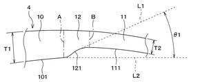
- the plurality of wings 4 have a thick portion 10, a thin portion 11, and a step portion 12.
- the thick portion 10 is a thick portion of the blade 4 formed on the leading edge 8 side.
- the negative pressure surface of the thick portion 10 is formed as an arcuate curved surface that is convex toward the positive pressure surface side.
- the curved surface of the negative pressure surface of the thick portion 10 is referred to as a first curved surface 101.
- the plate thickness T1 of the thick portion 10 is preferably set to, for example, 3 mm or more.
- both the radius of curvature of the positive pressure surface side and the radius of curvature of the negative pressure surface of the leading edge 8 of the blade 4 it is preferable to set both the radius of curvature of the positive pressure surface side and the radius of curvature of the negative pressure surface of the leading edge 8 of the blade 4 to 1.5 mm or more. ..
- the thin-walled portion 11 is provided on the downstream side of the thick-walled portion 10 (that is, on the trailing edge 9 side of the thick-walled portion 10) of the wing 4, and is a portion thinner than the thick-walled portion 10.
- the negative pressure surface of the thin wall portion 11 is also formed into an arcuate curved surface that is convex toward the positive pressure surface side.
- the curved surface of the negative pressure surface of the thin wall portion 11 is referred to as a second curved surface 111.
- the second curved surface 111 of the thin portion 11 is located on the positive pressure surface side with respect to the first curved surface 101 of the thick portion 10 described above.
- the plate thickness T2 of the thin portion 11 is set to, for example, 75% or less with respect to the plate thickness T1 of the thick portion 10. The reason will be described later.
- the step portion 12 is provided between the thick portion 10 and the thin portion 11, and is a portion where the plate thickness decreases from the thick portion 10 side toward the thin wall portion 11 side toward the positive pressure surface side. That is, the step portion 12 can be said to be a plate thickness reduction portion in which the plate thickness decreases from the upstream side to the downstream side.
- the boundary between the thick portion 10 and the step portion 12 is indicated by the alternate long and short dash line A, and the boundary between the step portion 12 and the thin portion 11 is indicated by the alternate long and short dash line B.
- these boundary lines are described for the sake of explanation, and in reality, the thick portion 10, the step portion 12, and the thin wall portion 11 are integrally formed.
- the negative pressure surface 121 of the step portion 12 connects the first curved surface 101 of the thick portion 10 and the second curved surface 111 of the thin portion 11 with a smooth curved surface shape. That is, the negative pressure surface at the boundary between the step portion 12 and the thick portion 10 has a smooth curved surface shape. Further, the negative pressure surface at the boundary between the step portion 12 and the thin wall portion 11 also has a smooth curved surface shape. Further, in the first embodiment, the negative pressure surface 121 of the step portion 12 is formed in a curved surface shape that is convex toward the positive pressure surface side in the cross-sectional view perpendicular to the rotation axis Ax of the blade 4.
- the tangent line at the center of the negative pressure surface 121 of the step portion 12 is referred to as the first tangent line L1.
- the tangent line of the portion of the negative pressure surface of the thick portion 10 on the stepped portion 12 side is referred to as a second tangent line L2.
- the angle ⁇ 1 formed by the first tangent line L1 and the second tangent line L2 is an acute angle.
- the angle ⁇ 1 formed by the first tangent line L1 and the second tangent line L2 is, for example, in the range of 20 ° to 70 °.
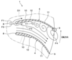
- step portion 12 is provided on the negative pressure surface of the blade 4 with cross hatching for the sake of explanation.
- the step portion 12 is provided at a position radially outside the inner diameter D1 of the suction port 5 of the shroud 2.
- the line obtained by dividing the wingspan into three equal parts is shown by the two-dot chain lines C and D.
- the wingspan means the length along the warp line of the wing 4.
- the step portion 12 is provided only in the central region when the wingspan is divided into three equal parts. Further, in the first embodiment, the step portion 12 has only a region between the boundary line C on the leading edge 8 side when the wingspan is divided into three equal parts and the boundary line E when the wingspan is divided into two equal parts. It is provided in.
- the air sucked from the suction port 5 flows from the leading edge 8 of the blade 4 to the inter-blade flow path.
- the air flowing in the vicinity of the leading edge 8 of the blade 4 flows through the inter-blade flow path along the positive pressure surface or the negative pressure surface of the blade 4 due to the Coanda effect.
- the inter-blade flow path suddenly expands from the step portion 12 provided in the middle of the blade 4. Therefore, the velocity boundary layer generated by the flow along the negative pressure surface of the blade 4 is disturbed starting from the boundary between the thick portion 10 and the step portion 12.
- the step portion 12 has a configuration in which the plate thickness decreases from the thick portion 10 side toward the thin wall portion 11 side toward the positive pressure surface side. Therefore, the vortex V1 having a large velocity gradient generated at the boundary between the thick portion 10 and the step portion 12 (that is, the separation point of the flow) hardly interferes with the negative pressure surface 121 of the step portion 12 and passes through the inter-blade flow path. It flows to the downstream side. Therefore, the noise generated at the boundary between the thick portion 10 and the step portion 12 (that is, the separation point of the flow) is small.
- the boundary between the step portion 12 and the thick portion 10 is connected by a smooth curved surface shape, and the boundary between the step portion 12 and the thin wall portion 11 is also a smooth curved surface. It is connected by a shape.
- the negative pressure surface 121 of the step portion 12 has a curved surface shape that is convex toward the positive pressure surface side. Therefore, even if the vortex V1 generated at the boundary between the thick portion 10 and the step portion 12 (that is, the separation point of the flow) interferes with the negative pressure surface 121 of the step portion 12, the noise generated there is small. ..
- the step portion 12 is not provided on the blade 4, and the negative pressure surface of the blade 4 is an arcuate curved surface extending from the leading edge 8 to the trailing edge 9. It is a composition formed by.
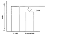
- FIG. 6 shows the experimental results comparing the noises of the turbofan 1 according to the first embodiment and the turbofan 100 of the comparative example.
- the turbofan 1 according to the first embodiment and the turbofan 100 of the comparative example were rotated at the same rotation speed, and the noise was compared.
- the turbofan 1 according to the first embodiment can reduce the noise by 1.5 dB as compared with the turbofan 100 of the comparative example.
- FIG. 7 shows the results of experiments on the relationship between the plate thickness reduction rate of the blade 4 and the low noise effect in the configuration of the turbofan 1 of the first embodiment.
- the plate thickness reduction ratio is a ratio in which the plate thickness T2 of the thin portion 11 is reduced with respect to the plate thickness T1 of the thick portion 10.
- the low noise effect becomes extremely large when the plate thickness reduction rate is 75% or less. Further, when the plate thickness reduction rate is 60% or less, it can be read that the low noise effect is 1.5 dB or more.
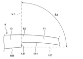
- the turbofan 1 of the present embodiment described above has the following effects.
- a step portion 12 that suddenly widens the inter-blade flow path is provided between the thick portion 10 and the thin-walled portion 11 of the blade 4.
- the velocity boundary layer generated by the flow along the negative pressure surface of the thick portion 10 is disturbed starting from the boundary between the thick portion 10 and the step portion 12, and the turbulent boundary layer is used as a separation point of the flow. It is possible to generate the mainstream F3 away from the negative pressure surface of the thin wall portion 11 toward the rear side in the rotation direction.
- this turbofan 1 shifts the position where the flow separation along the negative pressure surface of the blade 4 occurs forward as compared with the turbofan 100 of the above comparative example, and collides with the negative pressure surface of the trailing edge 9 of the blade 4. Noise can be reduced by reducing the speed gradient of the flow F4.
- the step portion 12 has a shape in which the plate thickness decreases from the upstream side to the downstream side toward the positive pressure surface side, the velocity gradient generated at the boundary between the thick portion 10 and the step portion 12 (that is, the separation point of the flow). It is possible to separate the interference distance between the large vortex V1 and the negative pressure surface 121 of the step portion 12. Therefore, it is possible to reduce the noise generated at the boundary between the thick portion 10 and the step portion 12 (that is, the separation point of the flow).
- the step portion 12 is provided in the central region when the wingspan is divided into three equal parts.
- the region on the leading edge 8 side hereinafter referred to as "front region” when the blade length is divided into three equal parts, the flow flowing from the inlet of the blade 4 flows along the wall surface of the blade 4, and the flow flows. It is not preferable to provide the step portion 12 because it has a function of increasing the robustness with respect to the inflow angle.
- a step portion 12 is provided in a region on the trailing edge 9 side (hereinafter referred to as "rear region) when the wingspan is divided into three equal parts, a vortex having a large speed gradient separated from the step portion 12 is generated in the blade 4.
- the turbofan 1 of the present embodiment can reduce noise by reducing the velocity gradient of the flow F4 that collides with the negative pressure surface of the trailing edge 9 of the blade 4.
- the step portion 12 is provided at a position radially outside the inner diameter D1 of the suction port 5 of the shroud 2.
- a step portion 12 is provided at a position radially inside the inner diameter D1 of the suction port 5 of the shroud 2
- the flow flowing in from the inlet of the blade 4 flows from the leading edge 8 of the blade 4 to the thick portion 10. It becomes difficult to flow along the wall surface into the inter-blade flow path.
- the step portion 12 since the step portion 12 is not provided at a position radially inside the inner diameter D1 of the suction port 5 of the shroud 2, the flow flowing from the inlet of the blade 4 flows from the leading edge 8 of the blade 4. It is possible to flow along the wall surface of the thick portion 10 into the inter-blade flow path. Therefore, the robustness to the inflow angle of the flow can be improved.
- the negative pressure surface at the boundary between the step portion 12 and the thick portion 10 has a smooth curved surface shape.
- the boundary between the thick portion 10 and the step portion 12 (that is, the separation point of the flow) is formed by not forming a corner portion on the negative pressure surface at the boundary between the step portion 12 and the thick portion 10. Even if the vortex V1 is generated in, the noise generated there can be reduced.
- the plate thickness T2 of the thin portion 11 it is preferable to set the plate thickness T2 of the thin portion 11 to 75% or less with respect to the plate thickness T1 of the thick portion 10. According to this, according to the above-mentioned experimental results, it is possible to extremely increase the low noise effect by setting the plate thickness T2 of the thin portion 11 to 75% or less with respect to the plate thickness T1 of the thick portion 10. .. According to the above-mentioned experimental results, noise can be reduced by 1.5 dB or more.
- the negative pressure surface 121 of the step portion 12 has a curved surface shape that is convex toward the positive pressure surface side in the cross-sectional view perpendicular to the rotation axis Ax of the blade 4. According to this, the distance between the vortex generated at the boundary between the thick portion 10 and the step portion 12 (that is, the separation point of the flow) and the negative pressure surface 121 of the step portion 12 becomes long, and therefore the noise generated there. Can be reduced.
- the radius of curvature of the leading edge 8 of the blade 4 on the positive pressure surface side and the radius of curvature of the negative pressure surface are both 1.5 mm or more. It is preferable to set to. Moreover, it is preferable that the plate thickness T1 of the leading edge 8 of the blade 4 is set to 3 mm or more. According to this, by increasing the plate thickness T1 of the leading edge 8, it is possible to allow the flow flowing from the suction port of the blade 4 to flow from the leading edge 8 of the blade 4 along the wall surface to the inter-blade flow path. be. Therefore, the robustness to the inflow angle of the flow can be improved.
- the second embodiment will be described with reference to FIG.
- the second embodiment is a modification of the configuration of the step portion 12 of the wing 4 with respect to the first embodiment, and the other parts are the same as those of the first embodiment. Therefore, only the portion different from the first embodiment is used. explain.
- FIG. 8 the position where the step portion 12 is provided on the negative pressure surface of the blade 4 is shown with cross hatching for the sake of explanation. Further, the virtual line H including the contact point P between the trailing edge 9 of the blade 4 and the shroud 2 and perpendicular to the rotation axis Ax is shown by a two-dot chain line.
- the step portion 12 is formed in the height range of the trailing edge 9 of the wing 4. That is, the step portion 12 is formed between the virtual line H and the main plate 3. According to this configuration, it is possible to keep the mainstream away from the negative pressure surface of the trailing edge 9 of the wing 4 toward the rear side in the rotational direction within the height range of the trailing edge 9 of the wing 4. Therefore, the noise generated at the trailing edge 9 of the blade 4 can be reduced.
- the third embodiment will be described with reference to FIG.
- the third embodiment is also a modification of the configuration of the step portion 12 with respect to the first embodiment and the like, and the other parts are the same as those of the first embodiment and the like. explain.
- the position where the step portion 12 is provided on the negative pressure surface of the blade 4 is shown with cross hatching for the sake of explanation.
- the step portion 12 is formed so as to extend radially inward from the shroud 2 side toward the main plate 3 side.
- the fast flow on the main plate 3 side is separated from the trailing edge 9 at a position far from the trailing edge 9, so that the rear side in the rotation direction from the negative pressure surface of the trailing edge 9 of the blade 4 It is possible to move the mainstream further away. Therefore, it is possible to reduce the flow velocity gradient of the flow colliding with the negative pressure surface of the trailing edge 9 of the blade 4 and reduce noise.
- the fourth embodiment will be described with reference to FIG.
- the fourth embodiment is a modification of the configuration of the step portion 12 with respect to the first embodiment and the like, and the other parts are the same as those of the first embodiment and the like. Therefore, only the parts different from the fourth embodiment and the like are used. explain.
- the angle ⁇ 2 formed by the second tangent line L2 of the portion of the negative pressure surface on the step portion 12 side is about 90 °.
- the velocity boundary layer generated by the flow along the negative pressure surface of the thick portion 10 is disturbed starting from the boundary between the thick portion 10 and the step portion 12, and the turbulent boundary is used as the separation point of the flow. It is possible to generate a layer and keep the mainstream away from the negative pressure surface of the thin wall portion 11 toward the rear side in the rotation direction. Therefore, also in the fourth embodiment, the position where the flow separation along the negative pressure surface of the blade 4 occurs is shifted forward, and the velocity gradient of the flow colliding with the negative pressure surface of the trailing edge 9 of the blade 4 is reduced to reduce noise. Can be reduced.
- the turbofan 1 has been described as a closed fan in which a main plate 3, a shroud 2, and a plurality of blades 4 are integrally formed, but the present invention is not limited to this.
- the turbofan 1 may be an open fan in which the main plate 3 and the plurality of blades 4 are integrally configured, and the plurality of blades 4 and the shroud 2 are configured as separate members.
- the step portion 12 is between the boundary line C on the leading edge 8 side when the blade length is divided into three equal parts and the boundary line E when the blade length is divided into two equal parts. Although it has been described as being provided only in the area, it is not limited to this.
- the step portion 12 is provided in the region between the boundary line C on the leading edge 8 side when the wingspan is divided into three equal parts and the boundary line D on the trailing edge 9 side when the wingspan is divided into three equal parts. Just do it.
- the plate thickness T1 of the thick portion 10 is preferably set to, for example, 3 mm or more, and the radius of curvature of the leading edge 8 of the blade 4 on the positive pressure surface side and the radius of curvature of the negative pressure surface. It was explained that it is preferable to set all of them to 1.5 mm or more, but the present invention is not limited to this.
- the plate thickness T1 of the thick portion 10 and the radius of curvature of the leading edge 8 in the cross-sectional view perpendicular to the rotation axis Ax can be arbitrarily set.
- the present disclosure is not limited to the above-described embodiment, and can be changed as appropriate. Further, the above embodiments are not unrelated to each other, and can be appropriately combined unless the combination is clearly impossible. Further, in each of the above embodiments, it goes without saying that the elements constituting the embodiment are not necessarily essential except when it is clearly stated that they are essential or when they are clearly considered to be essential in principle. stomach. Further, in each of the above embodiments, when numerical values such as the number, numerical values, quantities, and ranges of the constituent elements of the embodiment are mentioned, when it is clearly stated that they are particularly essential, and when it is clearly limited to a specific number in principle. It is not limited to the specific number except when it is done. Further, in each of the above embodiments, when the shape, positional relationship, etc. of the constituent elements are referred to, the shape, unless otherwise specified or limited in principle to a specific shape, positional relationship, etc. It is not limited to the positional relationship.
- the turbofan includes a shroud having an air suction port, a main plate provided in the direction of rotation of the shroud, and a shroud and a main plate. It is provided with a plurality of wings provided around the axis of rotation between the blades.
- the plurality of blades provided in the turbofan have a thick portion, a thin portion, and a step portion.
- the thick portion is a thick portion formed on the front edge side.
- the thin-walled portion is provided on the trailing edge side of the thick-walled portion, and is a portion having a thinner plate thickness than the thick-walled portion.
- the step portion is provided between the thick portion and the thin portion, and is a portion where the plate thickness decreases from the thick portion side toward the thin portion side toward the positive pressure surface side. Then, in a cross-sectional view perpendicular to the rotation axis of the blade, the arc-shaped second curved surface forming the negative pressure surface of the thin-walled portion is the positive pressure surface with respect to the arc-shaped first curved surface forming the negative pressure surface of the thick portion. It is located on the side, and the first curved surface and the second curved surface are connected by the negative pressure surface of the stepped portion.
- the step portion is provided in the central region when the wingspan is divided into three equal parts. According to this, since the step portion is not provided in the front region, it is possible to improve the robustness with respect to the inflow angle of the flow. Then, the flow flowing along the negative pressure surface of the thick portion is disturbed by the step portion provided in the central region, and a turbulent boundary layer is generated using this as the separation point of the flow, and the main flow is from the negative pressure surface to the rear side in the rotation direction. It is possible to keep away from. Therefore, noise can be reduced by reducing the velocity gradient of the flow colliding with the negative pressure surface of the trailing edge of the blade.
- the leading edge of the wing is located radially inside the inner diameter of the shroud suction port.
- the step portion is provided at a position radially outside the inner diameter of the suction port of the shroud. According to this, since the step portion is not provided at a position radially inside the inner diameter of the suction port of the shroud, the flow flowing from the inlet of the wing is made to flow along the wall surface of the thick portion from the leading edge of the wing. It is possible to flow in the inter-channel. Therefore, the robustness to the inflow angle of the flow can be improved.
- the negative pressure surface at the boundary between the stepped portion and the thick-walled portion has a smooth curved surface shape. According to this, even if a vortex is generated at the boundary between the thick portion and the step portion (that is, the separation point of the flow) by not forming a corner portion on the negative pressure surface at the boundary between the step portion and the thick portion. , The noise generated there can be reduced.
- the plate thickness of the thin portion is 75% or less with respect to the plate thickness of the thick portion. According to this, it was found from the experiments of the inventors that the low noise effect becomes extremely large when the plate thickness of the thin portion is 75% or less with respect to the plate thickness of the thick portion. According to the experiment, it is possible to reduce the noise by 1.5 dB or more.
- the negative pressure surface of the step portion is a curved surface that is convex toward the positive pressure surface side. According to this, the distance between the vortex generated at the boundary between the thick portion and the step portion (that is, the separation point of the flow) and the negative pressure surface of the step portion becomes long, so that the noise generated there should be reduced. Can be done.
- the tangent line of the central portion on the negative pressure surface of the step portion and the tangent line of the portion on the step portion side on the negative pressure surface of the thick portion are formed.
- the corners are acute. According to this, even if a vortex is generated at the boundary between the thick portion and the step portion (that is, the separation point of the flow) by not forming a corner portion on the negative pressure surface at the boundary between the step portion and the thick portion. , The noise generated there can be reduced.
- the radius of curvature of the positive pressure surface side and the radius of curvature of the negative pressure surface of the leading edge of the wing are both 1.5 mm or more, and The thickness of the leading edge of the wing is 3 mm or more. According to this, by increasing the plate thickness of the leading edge, it is possible to allow the flow flowing from the suction port of the blade to flow from the leading edge of the blade along the wall surface to the inter-blade flow path. Therefore, the robustness to the inflow angle of the flow can be improved.
- the step portion is formed at least in the height range of the trailing edge of the wing. According to this, it is possible to keep the mainstream away from the negative pressure surface of the trailing edge of the wing to the rear side in the rotation direction at least within the height range of the trailing edge of the wing, and it is possible to reduce the noise generated at the trailing edge of the wing. can.
- the step portion is formed so as to extend radially inward from the shroud side toward the main plate side. According to this, in order to correspond to the fast flow on the main plate side, it is possible to separate the negative pressure surface of the trailing edge of the wing from the main flow by separating the fast flow on the main plate side at a position far from the trailing edge. be. Therefore, it is possible to reduce the flow velocity gradient of the flow colliding with the negative pressure surface of the trailing edge of the blade and reduce noise.
Landscapes
- Engineering & Computer Science (AREA)
- Mechanical Engineering (AREA)
- General Engineering & Computer Science (AREA)
- Structures Of Non-Positive Displacement Pumps (AREA)
Priority Applications (2)
| Application Number | Priority Date | Filing Date | Title |
|---|---|---|---|
| CN202180061207.8A CN116134228A (zh) | 2020-07-14 | 2021-07-02 | 涡轮风扇 |
| US18/152,861 US12025148B2 (en) | 2020-07-14 | 2023-01-11 | Turbofan |
Applications Claiming Priority (2)
| Application Number | Priority Date | Filing Date | Title |
|---|---|---|---|
| JP2020120669A JP7409246B2 (ja) | 2020-07-14 | 2020-07-14 | ターボファン |
| JP2020-120669 | 2020-07-14 |
Related Child Applications (1)
| Application Number | Title | Priority Date | Filing Date |
|---|---|---|---|
| US18/152,861 Continuation US12025148B2 (en) | 2020-07-14 | 2023-01-11 | Turbofan |
Publications (1)
| Publication Number | Publication Date |
|---|---|
| WO2022014376A1 true WO2022014376A1 (ja) | 2022-01-20 |
Family
ID=79555364
Family Applications (1)
| Application Number | Title | Priority Date | Filing Date |
|---|---|---|---|
| PCT/JP2021/025145 Ceased WO2022014376A1 (ja) | 2020-07-14 | 2021-07-02 | ターボファン |
Country Status (4)
| Country | Link |
|---|---|
| US (1) | US12025148B2 (https=) |
| JP (1) | JP7409246B2 (https=) |
| CN (1) | CN116134228A (https=) |
| WO (1) | WO2022014376A1 (https=) |
Families Citing this family (1)
| Publication number | Priority date | Publication date | Assignee | Title |
|---|---|---|---|---|
| JP7697401B2 (ja) * | 2022-04-21 | 2025-06-24 | 株式会社デンソー | 送風機 |
Citations (4)
| Publication number | Priority date | Publication date | Assignee | Title |
|---|---|---|---|---|
| JPH09126190A (ja) * | 1995-10-30 | 1997-05-13 | Sanyo Electric Co Ltd | 遠心式送風機 |
| JP2006009577A (ja) * | 2004-06-22 | 2006-01-12 | Matsushita Electric Ind Co Ltd | 多翼ファン |
| WO2008111368A1 (ja) * | 2007-03-14 | 2008-09-18 | Mitsubishi Electric Corporation | 遠心ファン、空気調和機 |
| JP2016160905A (ja) * | 2015-03-05 | 2016-09-05 | パナソニックIpマネジメント株式会社 | 遠心ファン |
Family Cites Families (7)
| Publication number | Priority date | Publication date | Assignee | Title |
|---|---|---|---|---|
| DE3520218A1 (de) * | 1984-06-08 | 1985-12-12 | Hitachi, Ltd., Tokio/Tokyo | Laufrad fuer ein radialgeblaese |
| JP2000110782A (ja) * | 1998-09-30 | 2000-04-18 | Fujitsu General Ltd | ターボファン |
| CN1318765C (zh) * | 2003-12-15 | 2007-05-30 | 珠海格力电器股份有限公司 | 风机用叶轮、使用叶轮的风机及使用风机的空调器 |
| JP4994421B2 (ja) * | 2009-05-08 | 2012-08-08 | 三菱電機株式会社 | 遠心ファン及び空気調和機 |
| DE202010018509U1 (de) * | 2010-02-26 | 2017-03-15 | Ebm-Papst Mulfingen Gmbh & Co. Kg | Radial- oder Diagonal-Ventilatorrad |
| DE102012212896A1 (de) * | 2012-07-24 | 2014-02-20 | Continental Automotive Gmbh | Laufrad eines Abgasturboladers |
| JP6071394B2 (ja) | 2012-10-03 | 2017-02-01 | ミネベア株式会社 | 遠心式ファン |
-
2020
- 2020-07-14 JP JP2020120669A patent/JP7409246B2/ja active Active
-
2021
- 2021-07-02 CN CN202180061207.8A patent/CN116134228A/zh active Pending
- 2021-07-02 WO PCT/JP2021/025145 patent/WO2022014376A1/ja not_active Ceased
-
2023
- 2023-01-11 US US18/152,861 patent/US12025148B2/en active Active
Patent Citations (4)
| Publication number | Priority date | Publication date | Assignee | Title |
|---|---|---|---|---|
| JPH09126190A (ja) * | 1995-10-30 | 1997-05-13 | Sanyo Electric Co Ltd | 遠心式送風機 |
| JP2006009577A (ja) * | 2004-06-22 | 2006-01-12 | Matsushita Electric Ind Co Ltd | 多翼ファン |
| WO2008111368A1 (ja) * | 2007-03-14 | 2008-09-18 | Mitsubishi Electric Corporation | 遠心ファン、空気調和機 |
| JP2016160905A (ja) * | 2015-03-05 | 2016-09-05 | パナソニックIpマネジメント株式会社 | 遠心ファン |
Also Published As
| Publication number | Publication date |
|---|---|
| JP7409246B2 (ja) | 2024-01-09 |
| US12025148B2 (en) | 2024-07-02 |
| JP2022017860A (ja) | 2022-01-26 |
| CN116134228A (zh) | 2023-05-16 |
| US20230141673A1 (en) | 2023-05-11 |
Similar Documents
| Publication | Publication Date | Title |
|---|---|---|
| JP4994421B2 (ja) | 遠心ファン及び空気調和機 | |
| CN107795516B (zh) | 轴流风扇及室外机 | |
| WO2006011333A1 (ja) | 送風機 | |
| KR101251130B1 (ko) | 프로펠러 팬 | |
| JP5396965B2 (ja) | 軸流送風機、空気調和機及び換気扇 | |
| WO2019150567A1 (ja) | 軸流送風機 | |
| CN106884804B (zh) | 离心式鼓风机 | |
| JP5682751B2 (ja) | 多翼送風機 | |
| JP6330738B2 (ja) | 遠心送風機及びこれを用いた空気調和機 | |
| JP4818310B2 (ja) | 軸流送風機 | |
| JP2017203427A (ja) | ターボチャージャ | |
| WO2023199731A1 (ja) | 遠心ファン | |
| CN115443382A (zh) | 送风机 | |
| WO2022014376A1 (ja) | ターボファン | |
| JP6932295B1 (ja) | 送風機 | |
| JP2019127865A (ja) | 遠心ファン | |
| WO2021059899A1 (ja) | 送風機 | |
| JP7413973B2 (ja) | 送風機 | |
| WO2020100459A1 (ja) | 遠心ファン | |
| JP7487854B1 (ja) | 送風機 | |
| JP2021055669A (ja) | 送風機 | |
| WO2016075955A1 (ja) | 羽根車及び遠心圧縮機 | |
| JP7697401B2 (ja) | 送風機 | |
| CN116066412B (zh) | 有叶扩散器以及离心压缩机 | |
| JP6038320B2 (ja) | 多翼送風機 |
Legal Events
| Date | Code | Title | Description |
|---|---|---|---|
| 121 | Ep: the epo has been informed by wipo that ep was designated in this application |
Ref document number: 21842725 Country of ref document: EP Kind code of ref document: A1 |
|
| NENP | Non-entry into the national phase |
Ref country code: DE |
|
| 122 | Ep: pct application non-entry in european phase |
Ref document number: 21842725 Country of ref document: EP Kind code of ref document: A1 |