WO2022014286A1 - ガラス物品の製造方法 - Google Patents
ガラス物品の製造方法 Download PDFInfo
- Publication number
- WO2022014286A1 WO2022014286A1 PCT/JP2021/023804 JP2021023804W WO2022014286A1 WO 2022014286 A1 WO2022014286 A1 WO 2022014286A1 JP 2021023804 W JP2021023804 W JP 2021023804W WO 2022014286 A1 WO2022014286 A1 WO 2022014286A1
- Authority
- WO
- WIPO (PCT)
- Prior art keywords
- state
- glass
- adjusting tank
- molten glass
- manufacturing
- Prior art date
- Legal status (The legal status is an assumption and is not a legal conclusion. Google has not performed a legal analysis and makes no representation as to the accuracy of the status listed.)
- Ceased
Links
Images




Classifications
-
- C—CHEMISTRY; METALLURGY
- C03—GLASS; MINERAL OR SLAG WOOL
- C03B—MANUFACTURE, SHAPING, OR SUPPLEMENTARY PROCESSES
- C03B17/00—Forming molten glass by flowing-out, pushing-out, extruding or drawing downwardly or laterally from forming slits or by overflowing over lips
- C03B17/06—Forming glass sheets
Definitions
- This disclosure relates to a method for manufacturing glass articles.
- a process of forming a glass ribbon which is a source of glass articles by using an overflow down draw method is known.
- a state adjusting tank, a supply pipe, and a molded body arranged in order from the upstream side of the flow of the molten glass are used.
- the state adjustment tank adjusts the state (viscosity and flow rate) of the molten glass that has flowed into the tank and causes it to flow out of the tank.
- the molten glass flowing out of the state adjustment tank is supplied to the molded body through the supply pipe. Then, the glass ribbon is molded from the molten glass supplied to the molded body.
- the supply pipe includes a small-diameter pipe that is relatively upstream and connected to the state adjustment tank, and a large-diameter pipe that is relatively downstream and connected to the molded body.
- the downstream end of the small diameter pipe is housed in the upstream end of the large diameter pipe, and a gap is formed between the outer peripheral surface of the small diameter pipe and the inner peripheral surface of the large diameter pipe. , It has a structure to be connected.
- Patent Document 1 has the following problems to be solved.
- the technical problem to be solved in view of the above circumstances is that when the glass ribbon is molded by the overflow downdraw method when manufacturing the glass article, the small diameter pipe connected to the state adjusting tank and the molded body are connected. It is to avoid welding with large diameter pipes.
- the method for manufacturing the glass article for solving the above problems is a state adjusting tank that adjusts the state of the molten glass that has flowed into the tank and causes it to flow out of the tank, and glass by an overflow down draw method from the supplied molten glass.
- a glass article using a molded body that forms a ribbon and a supply pipe that supplies molten glass flowing out of the state adjusting tank to the molded body, it is arranged relatively upstream and connected to the state adjusting tank.
- a supply pipe including a small-diameter pipe to be formed and a large-diameter pipe arranged relatively downstream and connected to the molded body is used to form an outer peripheral surface of the small-diameter pipe and an inner peripheral surface of the large-diameter pipe.
- the structure is such that both pipes are connected with a gap formed between them, and as a preparatory step for starting the molding of the glass ribbon, the state adjusting tank, the supply pipe, and the molded body are connected. It is a method including a connection step and a temperature raising step of raising the temperature of the three parties to a state where the molten glass can be accepted, and is characterized by executing the connection step before the completion of the temperature raising step.
- the connection step of connecting the three is executed before the completion of the temperature raising step of raising the temperature of the state adjusting tank, the supply pipe, and the molded body to a state where the glass ribbon can be molded. Therefore, when connecting the three parties, it is not necessary to connect the small diameter pipe and the large diameter pipe in a high temperature environment. Therefore, the workability can be significantly improved, and the small-diameter pipe and the large-diameter pipe can be connected with high accuracy. As a result, it is possible to avoid the occurrence of a situation in which the outer peripheral surface of the small diameter pipe and the inner peripheral surface of the large diameter pipe are erroneously contacted and the two pipes are welded due to this.
- the temperature raising step is performed in a state where the molten glass flow path in the state adjusting tank is blocked by the blocking member.
- a connecting step of connecting the state adjusting tank and the transfer device for transferring the molten glass to the state adjusting tank is further provided, and the connecting step is a state. It is preferable that the molten glass flow path in the adjusting tank is blocked by the blocking member.
- a throttle portion is provided at the bottom of the state adjusting tank so that the cross-sectional area of the flow path gradually decreases as it moves to the downstream side of the molten glass flow path, and the blocking member follows the shape of the throttle portion. It is preferable that the molten glass flow path is blocked by providing a tapered tip portion and arranging the tip portion of the blocking member in the throttle portion.
- the drawn portion has a shape in which the cross-sectional area of the channel gradually decreases as it moves to the downstream side of the molten glass flow path, and the tip portion of the blocking member has a shape of the drawn portion. Since it is tapered accordingly, the molten glass flow path can be easily and effectively blocked by a blocking member.
- the ceiling portion of the state adjusting tank is provided with a ceiling opening for inserting the blocking member into the state adjusting tank, and the ceiling opening is closed during the execution of the temperature raising step.
- the temperature raising step is performed in a state where the transport path for transporting the glass ribbon is closed by the opening / closing body arranged below the molded body.
- the glass ribbon when the glass ribbon is molded by the overflow downdraw method in manufacturing the glass article, it is connected to a small diameter pipe connected to a state adjusting tank and a molded body. Welding with large diameter pipes can be avoided.
- platinum in the following description may be any of pure platinum, platinum alloy (platinum rhodium, etc.), and reinforced platinum (platinum containing zirconia, etc.) unless otherwise specified.
- platinum platinum alloy
- reinforced platinum platinum containing zirconia, etc.
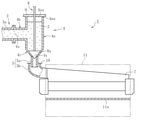
- the manufacturing apparatus 1 includes a transfer device 3 for transferring the molten glass 2 in order from the upstream side of the flow of the molten glass 2, and a state adjusting tank for adjusting the state of the molten glass 2. 4.
- a supply pipe 5 for supplying the molten glass 2 and a molded body 7 for forming a glass ribbon 6 which is a source of a glass article from the molten glass 2 are provided.
- the transfer device 3 adjusts the state of the molten glass 2 that has been generated from the glass raw material in the melting furnace and then sequentially passed through the clarification tank (tank for defoaming) and the stirring tank (tank for homogenization). It has a function of transferring to the tank 4.
- the manufacturing apparatus 1 of the present embodiment includes a melting furnace, a clarification tank, a stirring tank, and the like. Note that FIG. 1 illustrates only the transfer pipe 3a arranged on the most downstream side of the transfer device 3.
- the transfer pipe 3a can be connected to and disconnected from the state adjusting tank 4.
- the transfer pipe 3a is made of platinum.
- the state adjusting tank 4 has a function of adjusting the state (for example, viscosity and flow rate) of the molten glass 2 that has flowed into the tank and causing it to flow out of the tank.
- the state adjusting tank 4 includes a main body portion 4a, an inflow portion 4b connected to the side of the main body portion 4a, and a throttle portion 4c connected to the lower side of the main body portion 4a.
- the main body portion 4a, the inflow portion 4b, and the throttle portion 4c are all made of platinum, and can be energized and heated.
- the inflow portion 4b has an inflow port 4x at its upstream end for allowing the molten glass 2 to flow into the state adjusting tank 4.
- the inflow port 4x can be closed under a state where the connection with the transfer pipe 3a is released.
- the throttle portion 4c is a portion corresponding to the bottom of the state adjustment tank 4.
- the throttle portion 4c has a shape in which the cross-sectional area of the flow path gradually decreases as it moves to the downstream side (downward in the present embodiment) of the molten glass flow path in the state adjusting tank 4.
- the throttle portion 4c has an outlet 4y at its downstream end for allowing the molten glass 2 to flow out of the state adjusting tank 4.
- the main body portion 4a has a ceiling portion 4aa in which a ceiling opening 4ax is formed.
- the needle 8 (blocking member) described later can be inserted into the state adjusting tank 4 through the ceiling opening 4ax.
- the ceiling opening 4ax is closed by a lid 9 made of a refractory whose surface is covered with platinum.
- a through hole is formed in the lid body 9, and the needle 8 penetrates the through hole.
- the needle 8 has a tip portion 8a that tapers according to the shape of the throttle portion 4c, and can be moved along the vertical direction.
- the needle 8 is made of platinum.
- the supply pipe 5 has a function of supplying the molten glass 2 flowing out of the state adjusting tank 4 to the molded body 7.
- the supply pipe 5 includes a small-diameter pipe 5a arranged relatively upstream and connected to the state adjusting tank 4, and a large-diameter pipe 5b arranged relatively downstream and connected to the molded body 7. I'm out.
- both the small diameter pipe 5a and the large diameter pipe 5b are made of platinum, and can be energized and heated. Further, in the present embodiment, the coefficients of thermal expansion of both pipes 5a and 5b are the same.
- the small diameter pipe 5a extends linearly along the vertical direction.
- the large diameter pipe 5b is curved in order to change the flow direction of the molten glass 2.
- Both pipes 5a and 5b are connected in a state where the downstream end of the small diameter pipe 5a is accommodated in the upstream end of the large diameter pipe 5b.
- the downstream end of the small diameter pipe 5a and the upstream end of the large diameter pipe 5b form a double pipe structure, and a gap is formed between the outer peripheral surface of the small diameter pipe 5a and the inner peripheral surface of the large diameter pipe 5b.
- Ru The width of the gap is, for example, 5 mm to 50 mm.
- the gap is closed by a sealing member such as a lid 10 provided at the upstream end of the large-diameter pipe 5b.
- a sealing member such as a lid 10 provided at the upstream end of the large-diameter pipe 5b.
- the overlap margin (overlapping length along the vertical direction) between the downstream end of the small diameter pipe 5a and the upstream end of the large diameter pipe 5b can be changed when adjusting the height position of the molded body.
- Both pipes 5a and 5b are housed in casing, respectively, and the relative positions of both pipes 5a and 5b are determined by fixing each casing.
- the molded body 7 has a function of forming a glass ribbon 6 from the supplied molten glass 2 by an overflow down draw method.
- the molded body 7 is housed inside the molding chamber 11 and is surrounded by a wall portion (side wall or ceiling wall) of the molding chamber 11.
- the molded body 7 is heated in the molding chamber 11 by a heating means such as a heater.
- a slow cooling furnace (not shown) for slowly cooling the glass ribbon 6 is arranged in the lower stage of the molding chamber 11, and a cooling chamber (not shown) for cooling the glass ribbon 6 to room temperature is arranged in the lower stage of the slow cooling furnace.
- the lower part of the molding chamber 11, the slow cooling furnace, and the cooling chamber form a transport path for transporting the glass ribbon 6.
- the molding chamber 11 is provided with an opening / closing body 11a for opening and closing the molding chamber 11 (transport path) below the molded body 7.
- the opening / closing body 11a is composed of a pair of plate-shaped members having heat resistance, and the pair of plate-shaped members separate from each other along the direction perpendicular to the paper surface in FIG. 1 to open the molding chamber 11. Is possible.
- the slow cooling furnace or the cooling chamber may be provided with an opening / closing body.
- a method for manufacturing a glass article using the above-mentioned manufacturing apparatus 1 will be described.
- a connection step (FIG. 2), a temperature rise step (FIG. 3), a connection step (FIG. 4), The storage step (FIG. 5) and the supply step (FIG. 6) are executed.
- the state adjusting tank 4, the supply pipe 5, and the molded body 7 are connected.
- both pipes are formed so that a gap is formed between the outer peripheral surface of the small diameter pipe 5a and the inner peripheral surface of the large diameter pipe 5b.
- the 5a and 5b are connected in a accurately positioned state. Specifically, both pipes 5a and 5b are connected between the downstream end of the small diameter pipe 5a and the upstream end of the large diameter pipe 5b under a state where the center lines of the pipes are aligned with each other.
- the center lines of the pipes do not have to match as long as a gap is formed between the outer peripheral surface of the small diameter pipe 5a and the inner peripheral surface of the large diameter pipe 5b.
- the tripartites 4, 5 and 7 are connected at room temperature (for example, 20 ° C. ⁇ 15 ° C.).
- connection step the following (A) to (C) are performed as preparations for the temperature raising step to be executed later.
- A) By arranging the tip portion 8a of the needle 8 in the throttle portion 4c of the state adjustment tank 4, the molten glass flow path in the state adjustment tank 4 is blocked.
- B) The inflow port 4x of the state adjustment tank 4 is closed with a lid 12 made of a heat insulating material.
- C) The molding chamber 11 (transport path) is closed by the opening / closing body 11a provided in the molding chamber 11. The transport path may be closed by an opening / closing body provided in the slow cooling furnace or the cooling chamber.
- the temperature of the state adjusting tank 4, the supply pipe 5, and the molded body 7 is raised to a state where the molten glass 2 can be accepted.
- the tripartites 4, 5 and 7 are heated to raise the temperature from room temperature to about 1000 ° C to 1300 ° C.
- the tip portion 8a of the needle 8 since the molten glass flow path in the state adjusting tank 4 is blocked by the tip portion 8a of the needle 8, it is possible to prevent heat from escaping from the side of the molded body 7 and the supply pipe 5 to the state adjusting tank 4 side. It will be easier to do. Therefore, it is possible to raise the temperature of the molded body 7 while preventing a sudden temperature change of the molded body 7, and structural defects (chips, cracks, etc.) may occur in the molded body 7 due to the thermal shock. It can be avoided.
- the state adjusting tank 4 and the transfer device 3 are connected. Specifically, after removing the lid 12 that has blocked the inflow port 4x of the state adjusting tank 4 until the stage where the temperature raising step is completed, the transfer pipe 3a is connected to the inflow port 4x. At this time, the molten glass flow path in the state adjusting tank 4 is blocked by the tip portion 8a of the needle 8 as in the execution of the temperature raising step. As a result, an air flow of high-temperature gas that passes from the side of the molded body 7 and the supply pipe 5 to the upstream side through the state adjusting tank 4 is not generated, and the temperature of the molded body 7 and the supply pipe 5 is lowered. Can be prevented.
- the molten glass 2 is made to flow into the state adjusting tank 4 from the transfer pipe 3a, and the molten glass 2 is blocked on the upstream side of the tip portion 8a of the needle 8 arranged in the drawing portion 4c.
- the molten glass 2 is stored in the state adjusting tank 4.
- the viscosity of the molten glass 2 is also adjusted at the same time.
- the tip portion 8a of the needle 8 arranged in the throttle portion 4c of the state adjustment tank 4 is moved upward until the stage where the storage process is completed.
- the supply of the molten glass 2 from the state adjusting tank 4 to the molded body 7 is started through the supply pipes 5 (small diameter pipe 5a and large diameter pipe 5b).
- the molten glass 2 flowing from the drawing portion 4c into the small-diameter pipe 5a blocks the path of the high-temperature gas from the side of the molded body 7 and the supply pipe 5 to the upstream side. Therefore, it is possible to prevent the temperatures of the molded body 7 and the supply pipe 5 from dropping.
- FIG. 7 shows after the supply of the molten glass 2 to the molded body 7 is started. As shown, it is preferable to open the opening / closing body 11a when the molded body 7 is covered with the molten glass 2.
- the molded glass ribbon 6 is cut in the width direction to cut out a glass plate from the glass ribbon 6, or the glass ribbon 6 is wound into a roll to form a glass roll, thereby forming a glass plate as a glass article. And glass rolls are manufactured.
- connection process is executed before the temperature rise process is executed. Therefore, when connecting the state adjusting tank 4, the supply pipe 5, and the molded body 7, it is not necessary to connect the small diameter pipe 5a and the large diameter pipe 5b in a high temperature environment. Therefore, it is possible to connect the small diameter pipe 5a and the large diameter pipe 5b with high accuracy. As a result, it is possible to avoid the occurrence of a situation in which the outer peripheral surface of the small diameter pipe 5a and the inner peripheral surface of the large diameter pipe 5b are erroneously contacted, and as a result, both pipes 5a and 5b are welded.
- connection step is executed at room temperature before the temperature rise step is executed, but the temperature is raised as long as the accurate connection between the small diameter pipe 5a and the large diameter pipe 5b is not hindered.
- the connection process may be executed in the middle of the process (lower than normal temperature).
- the temperature of the small diameter pipe 5a and the large diameter pipe 5b in the connecting step is preferably 200 ° C. or lower, more preferably 100 ° C. or lower, and most preferably 50 ° C. or lower.
Landscapes
- Chemical & Material Sciences (AREA)
- Engineering & Computer Science (AREA)
- Materials Engineering (AREA)
- Organic Chemistry (AREA)
- Glass Melting And Manufacturing (AREA)
Abstract
溶融ガラス2の状態を調整する状態調整槽4と、溶融ガラス2からガラスリボン6を成形する成形体7と、溶融ガラス2を供給する供給パイプ5とを用いてガラス物品を製造するに際し、小径パイプ5aと大径パイプ5bとを含んだ供給パイプ5を使用し、小径パイプ5aの外周面と大径パイプ5bの内周面との間に隙間が形成された状態で両パイプ5a,5bが連結される構造とすると共に、ガラスリボン6の成形開始のための準備工程として、三者4,5,7を接続する接続工程と、三者4,5,7を昇温させる昇温工程とを備えるガラス物品の製造方法において、昇温工程の完了前に接続工程を実行するようにした。
Description
本開示は、ガラス物品の製造方法に関する。
ガラス板やガラスロールといったガラス物品を製造するための工程の一つとして、オーバーフローダウンドロー法を利用することで、ガラス物品の元となるガラスリボンを成形する工程が知られている。同工程では、ガラスリボンを成形するにあたり、溶融ガラスの流れの上流側から順番に配置された状態調整槽と、供給パイプと、成形体とを用いる。
状態調整槽は、槽内に流入した溶融ガラスの状態(粘度や流量)を調整して槽外に流出させる。状態調整槽から槽外に流出した溶融ガラスは、供給パイプを通じて成形体に供給される。そして、成形体に供給された溶融ガラスからガラスリボンが成形される。
供給パイプは、相対的に上流側に配置されて状態調整槽と接続される小径パイプと、相対的に下流側に配置されて成形体と接続される大径パイプとを含んでいる。これら両パイプは、小径パイプの下流端が大径パイプの上流端に収容された状態で、且つ、小径パイプの外周面と大径パイプの内周面との間に隙間が形成された状態で、連結される構造となっている。
ところで、ガラスリボンの成形を開始するにあたっては、そのための準備として、状態調整槽、供給パイプ、及び成形体の三者を接続すると共に、溶融ガラスを受け入れ可能な状態まで三者を昇温させる必要がある。ここで、特許文献1には、昇温を完了させた後、小径パイプ(降下管130)と大径パイプ(注入管132)とを連結し、状態調整槽(配送槽125)、供給パイプ(降下管130及び注入管132)、及び成形体(アイソパイプ135)を接続する形態が開示されている。
しかしながら、特許文献1に開示された形態には、下記のような解決すべき問題が存在している。
すなわち、同形態においては、昇温を完了させた後で小径パイプと大径パイプとを連結することから、極めて高温の環境下で両パイプを連結する必要があり、高精度の連結が困難であるという問題があった。そのため、本来隙間を介して対向するはずの小径パイプの外周面と大径パイプの内周面とが誤って接触してしまい、これに起因して両パイプが溶着してしまうような事態を招いていた。その結果、例えば、成形体の高さ位置を調節するにあたり、小径パイプと大径パイプの相対位置を変更するような場合に、各パイプを構成する白金や白金合金が破損してしまう等の不具合が生じていた。
上述の事情に鑑みて解決すべき技術的課題は、ガラス物品を製造するに際し、オーバーフローダウンドロー法によりガラスリボンを成形する場合に、状態調整槽と接続される小径パイプと、成形体と接続される大径パイプとの溶着を回避することである。
上記の課題を解決するためのガラス物品の製造方法は、槽内に流入した溶融ガラスの状態を調整して槽外に流出させる状態調整槽と、供給された溶融ガラスからオーバーフローダウンドロー法によりガラスリボンを成形する成形体と、状態調整槽から流出した溶融ガラスを成形体に供給する供給パイプと、を用いてガラス物品を製造するに際し、相対的に上流側に配置されて状態調整槽と接続される小径パイプと、相対的に下流側に配置されて成形体と接続される大径パイプと、を含んだ供給パイプを使用し、小径パイプの外周面と大径パイプの内周面との間に隙間が形成された状態で、両パイプが連結される構造とすると共に、ガラスリボンの成形を開始するための準備工程として、状態調整槽、供給パイプ、及び成形体の三者を接続する接続工程と、溶融ガラスを受け入れ可能な状態まで三者を昇温させる昇温工程と、を備える方法であって、昇温工程の完了前に、接続工程を実行することを特徴とする。
本方法では、ガラスリボンの成形が可能な状態まで状態調整槽、供給パイプ、及び成形体の三者を昇温させる昇温工程の完了前に、三者を接続する接続工程を実行する。このため、三者を接続するにあたって、小径パイプと大径パイプとを高温の環境下で連結するような必要がなくなる。従って、作業性を大幅に向上できると共に、小径パイプと大径パイプとを高精度に連結することが可能となる。その結果、小径パイプの外周面と大径パイプの内周面とが誤って接触し、これに起因して両パイプが溶着してしまうような事態の発生を回避できる。
上記の方法では、昇温工程が、状態調整槽内における溶融ガラス流路が遮断部材で遮られた状態で実行されることが好ましい。
このように溶融ガラス流路を遮断部材が遮ることで、成形体および供給パイプの側から状態調整槽を通過して上流側に向かうような、高温ガスの気流が発生し難くなる。これにより、状態調整槽や供給パイプの酸化を低減できると共に、状態調整槽や供給パイプ、成形体の温度低下を防止できる。
上記の方法では、準備工程として、昇温工程の実行後に、状態調整槽と、状態調整槽に溶融ガラスを移送するための移送装置と、を連結する連結工程を更に備え、連結工程は、状態調整槽内における溶融ガラス流路が遮断部材で遮られた状態で実行されることが好ましい。
このように溶融ガラス流路を遮断部材が遮ることで、成形体および供給パイプの側から状態調整槽を通過して上流側に向かうような、高温ガスの気流が発生し難くなる。このため、連結工程において、状態調整槽や供給パイプの酸化を低減できると共に、状態調整槽や供給パイプ、成形体の温度低下を防止できる。
上記の方法では、状態調整槽の底部に、溶融ガラス流路の下流側に移行するに連れて漸次に流路断面積が縮小する絞り部が設けられ、遮断部材に、絞り部の形状に倣って先細りする先端部が設けられ、遮断部材の先端部を絞り部に配置することで、溶融ガラス流路を遮ることが好ましい。
このようにすれば、絞り部が、溶融ガラス流路の下流側に移行するに連れて漸次に流路断面積が縮小する形状である上に、遮断部材の先端部が、絞り部の形状に倣って先細りしているため、溶融ガラス流路を遮断部材で簡便かつ効果的に遮ることができる。
上記の方法では、状態調整槽の天井部に、遮断部材を状態調整槽内に挿入するための天井開口が設けられ、昇温工程の実行中に、天井開口を封鎖することが好ましい。
このようにすれば、昇温工程の実行中に、状態調整槽の天井開口が封鎖されることから、状態調整槽の昇温を効率よく行うことが可能となる。
上記の方法では、昇温工程の実行中に、状態調整槽内に溶融ガラスを流入させるための流入口を封鎖することが好ましい。
このようにすれば、昇温工程の実行中に、状態調整槽の流入口が封鎖されるので、状態調整槽の昇温を更に効率よく行うことが可能となる。
上記の方法では、昇温工程は、ガラスリボンを搬送するための搬送路を成形体の下方に配置される開閉体で閉鎖した状態で実行されることが好ましい。
このように搬送路を開閉体で閉鎖することで、搬送路に沿って上昇するガスで成形体の温度(特に成形体の下端部の温度)が局所的に低下することを抑制できる。このため、サーマルショックに起因して成形体に構造欠陥(欠けやクラック等)が発生することを回避できる。
本開示に係るガラス物品の製造方法によれば、ガラス物品を製造するに際し、オーバーフローダウンドロー法によりガラスリボンを成形する場合に、状態調整槽と接続される小径パイプと、成形体と接続される大径パイプとの溶着を回避できる。
以下、実施形態に係るガラス物品の製造方法について、添付の図面を参照しながら説明する。なお、以下の説明における「白金」とは、特に断りが無い限りで、純白金、白金合金(白金ロジウム等)、強化白金(ジルコニアを含んだ白金等)のいずれであってもよい。まず、本製造方法に用いる製造装置について説明する。
図1に示すように、製造装置1は、溶融ガラス2の流れの上流側から順番に、溶融ガラス2を移送するための移送装置3と、溶融ガラス2の状態を調整するための状態調整槽4と、溶融ガラス2を供給するための供給パイプ5と、溶融ガラス2からガラス物品の元となるガラスリボン6を成形するための成形体7とを備えている。
移送装置3は、溶解炉でガラス原料から生成されたのち、清澄槽(脱泡のための槽)や撹拌槽(均質化のための槽)を順次に通過してきた溶融ガラス2を、状態調整槽4まで移送する機能を有する。換言すると、本実施形態の製造装置1は、溶解炉や清澄槽、撹拌槽等を備える。なお、図1においては、移送装置3のうちの最も下流側に配置された移送パイプ3aのみを図示している。移送パイプ3aは、状態調整槽4との連結、及び、連結の解除が可能となっている。移送パイプ3aは白金で構成されている。
状態調整槽4は、槽内に流入した溶融ガラス2の状態(例えば粘度や流量)を調整して槽外に流出させる機能を有する。状態調整槽4は、本体部4aと、本体部4aの側方に連なった流入部4bと、本体部4aの下方に連なった絞り部4cとを備えている。本体部4a、流入部4b、及び絞り部4cは、いずれも白金で構成されており、通電加熱が可能となっている。
流入部4bは、その上流端に溶融ガラス2を状態調整槽4内に流入させるための流入口4xを有する。流入口4xは、移送パイプ3aとの連結を解除した状態の下で封鎖することが可能となっている。
絞り部4cは、状態調整槽4の底部に相当する部位である。絞り部4cは、状態調整槽4内における溶融ガラス流路の下流側(本実施形態では下方)に移行するに連れて漸次に流路断面積が縮小する形状となっている。絞り部4cは、その下流端に溶融ガラス2を状態調整槽4外に流出させるための流出口4yを有する。
本体部4aは、天井開口4axが形成された天井部4aaを有する。この天井開口4axを通じて後述するニードル8(遮断部材)を状態調整槽4内に挿入することが可能である。天井開口4axは、表面が白金で覆われた耐火物でなる蓋体9により封鎖されている。蓋体9には貫通孔が形成されており、この貫通孔をニードル8が貫通している。ニードル8は、絞り部4cの形状に倣って先細りする先端部8aを有すると共に、上下方向に沿って移動させることが可能となっている。これにより、図1に二点鎖線で示すように、ニードル8が下限位置まで移動して先端部8aが絞り部4cに配置されると、状態調整槽4内における溶融ガラス流路が遮られた状態となる。なお、本実施形態では、ニードル8が白金で構成されている。
供給パイプ5は、状態調整槽4から流出した溶融ガラス2を成形体7に供給する機能を有する。供給パイプ5は、相対的に上流側に配置されて状態調整槽4と接続される小径パイプ5aと、相対的に下流側に配置されて成形体7と接続される大径パイプ5bとを含んでいる。なお、本実施形態では、小径パイプ5aおよび大径パイプ5bがいずれも白金で構成されており、通電加熱が可能となっている。また、本実施形態では、両パイプ5a,5bの熱膨張率が同一となっている。
小径パイプ5aは、上下方向に沿って直線的に延びている。これに対して、大径パイプ5bは、溶融ガラス2の流れ方向を転換させるために湾曲している。両パイプ5a,5bは、小径パイプ5aの下流端が大径パイプ5bの上流端に収容された状態で連結されている。これにより、小径パイプ5aの下流端と大径パイプ5bの上流端とが二重管構造をなし、小径パイプ5aの外周面と大径パイプ5bの内周面との間には隙間が形成される。隙間の幅は、一例として5mm~50mmである。隙間は、大径パイプ5bの上流端に備わった蓋10等の封止部材により封鎖されている。小径パイプ5aの下流端と大径パイプ5bの上流端との重なり代(上下方向に沿って重複した長さ)は、成形体の高さ位置の調節に際して変更することが可能である。両パイプ5a,5bは、それぞれケーシングに収容されており、各ケーシングを固定することに伴って両パイプ5a,5bの相対位置が決定される。
成形体7は、供給された溶融ガラス2からオーバーフローダウンドロー法によりガラスリボン6を成形する機能を有する。成形体7は、成形室11の内部に収容され、成形室11の壁部(側壁や天井壁)により囲われている。成形体7は、成形室11内でヒーター等の加熱手段により加熱される。成形室11の下段には、ガラスリボン6を徐冷する徐冷炉(図示なし)が配置され、その徐冷炉の下段には、ガラスリボン6を常温まで冷却する冷却室(図示なし)が配置される。成形室11の下部、徐冷炉及び冷却室は、ガラスリボン6を搬送する搬送路を構成する。
成形室11は、成形体7の下方に成形室11(搬送路)の開放、及び、閉鎖を行うための開閉体11aを備えている。開閉体11aは、耐熱性を有する一対の板状部材で構成されており、一対の板状部材が図1における紙面に鉛直な方向に沿って互いに離反することで、成形室11を開放することが可能となっている。なお、徐冷炉又は冷却室が開閉体を備えてもよい。
以下、上記の製造装置1を用いたガラス物品の製造方法について説明する。本製造方法では、ガラス物品の元となるガラスリボン6の成形を開始するための準備工程として、順番に、接続工程(図2)、昇温工程(図3)、連結工程(図4)、貯留工程(図5)、供給工程(図6)を実行する。
図2に示す接続工程では、状態調整槽4、供給パイプ5、及び成形体7の三者を接続する。このとき、供給パイプ5に含まれた小径パイプ5aと大径パイプ5bとについて、小径パイプ5aの外周面と大径パイプ5bの内周面との間に隙間が形成されるように、両パイプ5a,5bを正確に位置決めした状態で連結する。具体的には、小径パイプ5aの下流端と、大径パイプ5bの上流端との相互間で、パイプの中心線を一致させた状態の下で両パイプ5a,5bを連結する。しかしながらこの限りではなく、小径パイプ5aの外周面と大径パイプ5bの内周面との間に隙間が形成される限りで、パイプの中心線が一致していなくてもよい。本実施形態では、三者4,5,7の接続を常温下(例えば20℃±15℃)で行う。
さらに、接続工程においては、後に実行する昇温工程のための準備として、下記の(A)~(C)を行う。(A)ニードル8の先端部8aを状態調整槽4の絞り部4cに配置することで、状態調整槽4内における溶融ガラス流路を遮った状態とする。(B)状態調整槽4の流入口4xを断熱材でなる蓋12で封鎖した状態とする。(C)成形室11に備わった開閉体11aにより当該成形室11(搬送路)を閉鎖した状態とする。なお、徐冷炉又は冷却室に備わった開閉体により搬送路を閉鎖した状態としてもよい。
図3に示す昇温工程では、溶融ガラス2を受け入れ可能な状態まで状態調整槽4、供給パイプ5、及び成形体7の三者を昇温させる。例えば、三者4,5,7を加熱して常温から1000℃~1300℃程度まで昇温させる。このとき、状態調整槽4内の溶融ガラス流路がニードル8の先端部8aにより遮られていることで、成形体7および供給パイプ5の側から状態調整槽4側に熱が逃げることを回避しやすくなる。そのため、成形体7の急激な温度変化を防止しつつ当該成形体7を昇温させることが可能となり、サーマルショックに起因して成形体7に構造欠陥(欠けやクラック等)が発生することを回避できる。
図4に示す連結工程では、状態調整槽4と移送装置3とを連結する。具体的には、昇温工程が完了する段階まで状態調整槽4の流入口4xを封鎖していた蓋12を除去した上で、流入口4xに移送パイプ3aを連結する。このとき、昇温工程の実行中と同様に、状態調整槽4内の溶融ガラス流路がニードル8の先端部8aにより遮られた状態にある。これにより、成形体7および供給パイプ5の側から状態調整槽4を通過して上流側に向かうような、高温ガスの気流が発生しなくなり、成形体7および供給パイプ5の温度が低下することを防止できる。
図5に示す貯留工程では、移送パイプ3aから状態調整槽4内に溶融ガラス2を流入させると共に、絞り部4cに配置したニードル8の先端部8aよりも上流側において溶融ガラス2を堰き止める。これにより、状態調整槽4内に溶融ガラス2を貯留していく。このとき、溶融ガラス2の粘度の調整も同時に行う。
図6に示す供給工程では、貯留工程が完了する段階まで状態調整槽4の絞り部4cに配置していたニードル8の先端部8aを上方に移動させる。これにより、供給パイプ5(小径パイプ5aおよび大径パイプ5b)を通じて状態調整槽4から成形体7への溶融ガラス2の供給を開始する。このとき、絞り部4cから小径パイプ5aに流入する溶融ガラス2により、高温のガスが成形体7および供給パイプ5の側から上流側へ向かう経路が封鎖された状態となる。従って、成形体7および供給パイプ5の温度が低下することを防止できる。
成形体7への溶融ガラス2の供給が開始された後に、成形室11に備わった開閉体11aを開放する。これにより、成形体7から流下するガラスリボン6が、成形室11内から室外に移動するための経路が開かれる。サーマルショックに起因して成形体7に構造欠陥(欠けやクラック等)が発生することを確実に回避する観点では、成形体7への溶融ガラス2の供給が開始された後で、図7に示すように成形体7が溶融ガラス2で覆われた状態となった段階で、開閉体11aを開放することが好ましい。その後、成形されたガラスリボン6を幅方向に切断して当該ガラスリボン6からガラス板を切り出したり、ガラスリボン6をロール状に巻き取ってガラスロールとしたりすることで、ガラス物品としてのガラス板やガラスロールが製造される。
以下、上記のガラス物品の製造方法による主たる作用・効果について説明する。
上記の製造方法では、昇温工程の実行前に接続工程を実行している。このため、状態調整槽4、供給パイプ5、及び成形体7の三者を接続するにあたって、小径パイプ5aと大径パイプ5bとを高温の環境下で連結するような必要がなくなる。従って、小径パイプ5aと大径パイプ5bとを高精度に連結することが可能となる。その結果、小径パイプ5aの外周面と大径パイプ5bの内周面とが誤って接触し、これに起因して両パイプ5a,5bが溶着してしまうような事態の発生を回避できる。
ここで、上記の実施形態の変形例として、以下のような形態を採用してもよい。すなわち、上記の実施形態では、昇温工程の実行前に、常温下で接続工程を実行しているが、小径パイプ5aと大径パイプ5bとの正確な連結に支障がない限りで、昇温工程の途中(常温よりも高温下)で接続工程を実行するようにしてもよい。この場合、接続工程での小径パイプ5aと大径パイプ5bの温度が200℃以下であることが好ましく、100℃以下であることがより好ましく、50℃以下であることが最も好ましい。
2 溶融ガラス
3 移送装置
4 状態調整槽
4aa 天井部
4ax 天井開口
4c 絞り部
4x 流入口
5 供給パイプ
5a 小径パイプ
5b 大径パイプ
6 ガラスリボン
7 成形体
8 ニードル(遮断部材)
8a 先端部
3 移送装置
4 状態調整槽
4aa 天井部
4ax 天井開口
4c 絞り部
4x 流入口
5 供給パイプ
5a 小径パイプ
5b 大径パイプ
6 ガラスリボン
7 成形体
8 ニードル(遮断部材)
8a 先端部
Claims (7)
- 槽内に流入した溶融ガラスの状態を調整して槽外に流出させる状態調整槽と、供給された溶融ガラスからオーバーフローダウンドロー法によりガラスリボンを成形する成形体と、前記状態調整槽から流出した溶融ガラスを前記成形体に供給する供給パイプと、を用いてガラス物品を製造するに際し、
相対的に上流側に配置されて前記状態調整槽と接続される小径パイプと、相対的に下流側に配置されて前記成形体と接続される大径パイプと、を含んだ前記供給パイプを使用し、前記小径パイプの外周面と前記大径パイプの内周面との間に隙間が形成された状態で、両パイプが連結される構造とすると共に、
前記ガラスリボンの成形を開始するための準備工程として、前記状態調整槽、前記供給パイプ、及び前記成形体の三者を接続する接続工程と、前記溶融ガラスを受け入れ可能な状態まで前記三者を昇温させる昇温工程と、を備えるガラス物品の製造方法であって、
前記昇温工程の完了前に、前記接続工程を実行することを特徴とするガラス物品の製造方法。 - 前記昇温工程は、前記状態調整槽内における溶融ガラス流路が遮断部材で遮られた状態で実行されることを特徴とする請求項1に記載のガラス物品の製造方法。
- 前記準備工程として、前記昇温工程の実行後に、前記状態調整槽と、前記状態調整槽に溶融ガラスを移送するための移送装置と、を連結する連結工程を更に備え、
前記連結工程は、前記状態調整槽内における溶融ガラス流路が遮断部材で遮られた状態で実行されることを特徴とする請求項1又は2に記載のガラス物品の製造方法。 - 前記状態調整槽の底部に、前記溶融ガラス流路の下流側に移行するに連れて漸次に流路断面積が縮小する絞り部が設けられ、
前記遮断部材に、前記絞り部の形状に倣って先細りする先端部が設けられ、
前記遮断部材の先端部を前記絞り部に配置することで、前記溶融ガラス流路を遮ることを特徴とする請求項2又は3に記載のガラス物品の製造方法。 - 前記状態調整槽の天井部に、前記遮断部材を前記状態調整槽内に挿入するための天井開口が設けられ、
前記昇温工程の実行中に、前記天井開口を封鎖することを特徴とする請求項2~4のいずれかに記載のガラス物品の製造方法。 - 前記昇温工程の実行中に、前記状態調整槽内に溶融ガラスを流入させるための流入口を封鎖することを特徴とする請求項1~5のいずれかに記載のガラス物品の製造方法。
- 前記昇温工程は、前記ガラスリボンを搬送するための搬送路を前記成形体の下方に配置される開閉体で閉鎖した状態で実行されることを特徴とする請求項1~6のいずれかに記載のガラス物品の製造方法。
Priority Applications (2)
| Application Number | Priority Date | Filing Date | Title |
|---|---|---|---|
| CN202180034144.7A CN115515908B (zh) | 2020-07-16 | 2021-06-23 | 玻璃物品的制造方法 |
| KR1020227034805A KR102816356B1 (ko) | 2020-07-16 | 2021-06-23 | 유리 물품의 제조 방법 |
Applications Claiming Priority (2)
| Application Number | Priority Date | Filing Date | Title |
|---|---|---|---|
| JP2020-122186 | 2020-07-16 | ||
| JP2020122186A JP7536224B2 (ja) | 2020-07-16 | 2020-07-16 | ガラス物品の製造方法 |
Publications (1)
| Publication Number | Publication Date |
|---|---|
| WO2022014286A1 true WO2022014286A1 (ja) | 2022-01-20 |
Family
ID=79555262
Family Applications (1)
| Application Number | Title | Priority Date | Filing Date |
|---|---|---|---|
| PCT/JP2021/023804 Ceased WO2022014286A1 (ja) | 2020-07-16 | 2021-06-23 | ガラス物品の製造方法 |
Country Status (4)
| Country | Link |
|---|---|
| JP (1) | JP7536224B2 (ja) |
| KR (1) | KR102816356B1 (ja) |
| CN (1) | CN115515908B (ja) |
| WO (1) | WO2022014286A1 (ja) |
Citations (3)
| Publication number | Priority date | Publication date | Assignee | Title |
|---|---|---|---|---|
| WO2012132368A1 (ja) * | 2011-03-30 | 2012-10-04 | AvanStrate株式会社 | ガラス板の製造方法及びガラス板製造装置 |
| JP2019099418A (ja) * | 2017-12-01 | 2019-06-24 | 日本電気硝子株式会社 | ガラス物品の製造方法 |
| JP2019206461A (ja) * | 2018-05-30 | 2019-12-05 | 日本電気硝子株式会社 | ガラス物品の製造方法 |
Family Cites Families (9)
| Publication number | Priority date | Publication date | Assignee | Title |
|---|---|---|---|---|
| JP2000178837A (ja) * | 1998-12-16 | 2000-06-27 | Osaka Gas Engineering Co Ltd | 炭素繊維の賦活炉 |
| JP4711171B2 (ja) * | 2004-12-28 | 2011-06-29 | 日本電気硝子株式会社 | 板ガラス製造装置及び板ガラス製造方法 |
| JP5020492B2 (ja) * | 2005-08-19 | 2012-09-05 | Hoya株式会社 | モールドプレス成形装置および成形品の製造方法 |
| CN101652328B (zh) | 2007-02-22 | 2013-03-27 | 康宁股份有限公司 | 在接合过程中维护溢流槽的方法 |
| JP5438084B2 (ja) * | 2011-10-07 | 2014-03-12 | Hoya株式会社 | ガラス成形体の製造方法、及び、そのガラス成形体を用いる光学素子の製造方法 |
| JP6281747B2 (ja) * | 2014-03-13 | 2018-02-21 | 日本電気硝子株式会社 | ガラス物品の製造装置およびその製造方法 |
| JP7045643B2 (ja) * | 2018-05-28 | 2022-04-01 | 日本電気硝子株式会社 | ガラス物品の製造方法及び製造装置 |
| JP7198423B2 (ja) | 2018-06-27 | 2023-01-04 | 日本電気硝子株式会社 | ガラス物品の製造方法 |
| CN112119043B (zh) * | 2018-07-04 | 2023-04-14 | 日本电气硝子株式会社 | 玻璃物品的制造方法以及制造装置 |
-
2020
- 2020-07-16 JP JP2020122186A patent/JP7536224B2/ja active Active
-
2021
- 2021-06-23 WO PCT/JP2021/023804 patent/WO2022014286A1/ja not_active Ceased
- 2021-06-23 CN CN202180034144.7A patent/CN115515908B/zh active Active
- 2021-06-23 KR KR1020227034805A patent/KR102816356B1/ko active Active
Patent Citations (3)
| Publication number | Priority date | Publication date | Assignee | Title |
|---|---|---|---|---|
| WO2012132368A1 (ja) * | 2011-03-30 | 2012-10-04 | AvanStrate株式会社 | ガラス板の製造方法及びガラス板製造装置 |
| JP2019099418A (ja) * | 2017-12-01 | 2019-06-24 | 日本電気硝子株式会社 | ガラス物品の製造方法 |
| JP2019206461A (ja) * | 2018-05-30 | 2019-12-05 | 日本電気硝子株式会社 | ガラス物品の製造方法 |
Also Published As
| Publication number | Publication date |
|---|---|
| CN115515908B (zh) | 2025-11-04 |
| KR102816356B1 (ko) | 2025-06-04 |
| CN115515908A (zh) | 2022-12-23 |
| KR20230041646A (ko) | 2023-03-24 |
| JP7536224B2 (ja) | 2024-08-20 |
| JP2022018815A (ja) | 2022-01-27 |
Similar Documents
| Publication | Publication Date | Title |
|---|---|---|
| KR101629039B1 (ko) | 용융 유리 이송용 베셀들 간 연결부를 밀봉하는 장치 | |
| EP1832558B1 (en) | Plate glass manufacturing apparatus and plate glass manufacturing method | |
| US9796615B2 (en) | Glass processing device and bottom machine therefor for manufacturing glass containers | |
| KR102527850B1 (ko) | 용융 유리 컨디셔닝 장치 및 방법 | |
| TWI746726B (zh) | 用於控制流入玻璃成形機之玻璃流的方法及設備 | |
| JP6832346B2 (ja) | ガラス製造装置及びその動作方法 | |
| KR102331496B1 (ko) | 유리 제조 방법 및 유리 공급관의 예열 방법 | |
| TW201742832A (zh) | 用於玻璃管製造的鐘形組件與包含其之玻璃管製造設備 | |
| TWI761524B (zh) | 重整玻璃製造系統之方法 | |
| JP2022018815A (ja) | ガラス物品の製造方法 | |
| EP3173384B1 (en) | Glass melt production device and glass melt production method | |
| JP2012167004A (ja) | ガラス管の製造方法及び製造装置 | |
| CN116113602A (zh) | 用于形成玻璃物品的方法 | |
| CN216918999U (zh) | 具有泄漏缓解特征结构的玻璃制造设备 | |
| JP6206179B2 (ja) | 溶融ガラス供給装置、及びガラス板製造装置 | |
| TWI918926B (zh) | 具有洩漏緩解特徵結構之玻璃製造設備 | |
| KR20250094674A (ko) | 유리 제품을 제조하기 위한 장치 및 방법 | |
| CN110606652A (zh) | 玻璃基管生产系统及生产方法 | |
| JP2025130028A (ja) | ガラス物品の製造方法 | |
| CN120504474A (zh) | 管式玻璃窑炉装置 | |
| TW202012320A (zh) | 玻璃物品的製造方法 |
Legal Events
| Date | Code | Title | Description |
|---|---|---|---|
| 121 | Ep: the epo has been informed by wipo that ep was designated in this application |
Ref document number: 21841350 Country of ref document: EP Kind code of ref document: A1 |
|
| NENP | Non-entry into the national phase |
Ref country code: DE |
|
| 122 | Ep: pct application non-entry in european phase |
Ref document number: 21841350 Country of ref document: EP Kind code of ref document: A1 |
|
| WWG | Wipo information: grant in national office |
Ref document number: 202180034144.7 Country of ref document: CN |