WO2022014124A1 - 電池管理装置、電池管理方法、電力貯蔵システム - Google Patents
電池管理装置、電池管理方法、電力貯蔵システム Download PDFInfo
- Publication number
- WO2022014124A1 WO2022014124A1 PCT/JP2021/017554 JP2021017554W WO2022014124A1 WO 2022014124 A1 WO2022014124 A1 WO 2022014124A1 JP 2021017554 W JP2021017554 W JP 2021017554W WO 2022014124 A1 WO2022014124 A1 WO 2022014124A1
- Authority
- WO
- WIPO (PCT)
- Prior art keywords
- battery
- state
- value
- parameter
- temperature
- Prior art date
- Legal status (The legal status is an assumption and is not a legal conclusion. Google has not performed a legal analysis and makes no representation as to the accuracy of the status listed.)
- Ceased
Links
Images


Classifications
-
- G—PHYSICS
- G01—MEASURING; TESTING
- G01R—MEASURING ELECTRIC VARIABLES; MEASURING MAGNETIC VARIABLES
- G01R31/00—Arrangements for testing electric properties; Arrangements for locating electric faults; Arrangements for electrical testing characterised by what is being tested not provided for elsewhere
- G01R31/36—Arrangements for testing, measuring or monitoring the electrical condition of accumulators or electric batteries, e.g. capacity or state of charge [SoC]
- G01R31/367—Software therefor, e.g. for battery testing using modelling or look-up tables
-
- G—PHYSICS
- G01—MEASURING; TESTING
- G01R—MEASURING ELECTRIC VARIABLES; MEASURING MAGNETIC VARIABLES
- G01R31/00—Arrangements for testing electric properties; Arrangements for locating electric faults; Arrangements for electrical testing characterised by what is being tested not provided for elsewhere
- G01R31/36—Arrangements for testing, measuring or monitoring the electrical condition of accumulators or electric batteries, e.g. capacity or state of charge [SoC]
- G01R31/374—Arrangements for testing, measuring or monitoring the electrical condition of accumulators or electric batteries, e.g. capacity or state of charge [SoC] with means for correcting the measurement for temperature or ageing
-
- G—PHYSICS
- G01—MEASURING; TESTING
- G01R—MEASURING ELECTRIC VARIABLES; MEASURING MAGNETIC VARIABLES
- G01R31/00—Arrangements for testing electric properties; Arrangements for locating electric faults; Arrangements for electrical testing characterised by what is being tested not provided for elsewhere
- G01R31/36—Arrangements for testing, measuring or monitoring the electrical condition of accumulators or electric batteries, e.g. capacity or state of charge [SoC]
- G01R31/382—Arrangements for monitoring battery or accumulator variables, e.g. SoC
- G01R31/3842—Arrangements for monitoring battery or accumulator variables, e.g. SoC combining voltage and current measurements
-
- G—PHYSICS
- G01—MEASURING; TESTING
- G01R—MEASURING ELECTRIC VARIABLES; MEASURING MAGNETIC VARIABLES
- G01R31/00—Arrangements for testing electric properties; Arrangements for locating electric faults; Arrangements for electrical testing characterised by what is being tested not provided for elsewhere
- G01R31/36—Arrangements for testing, measuring or monitoring the electrical condition of accumulators or electric batteries, e.g. capacity or state of charge [SoC]
- G01R31/389—Measuring internal impedance, internal conductance or related variables
-
- G—PHYSICS
- G01—MEASURING; TESTING
- G01R—MEASURING ELECTRIC VARIABLES; MEASURING MAGNETIC VARIABLES
- G01R31/00—Arrangements for testing electric properties; Arrangements for locating electric faults; Arrangements for electrical testing characterised by what is being tested not provided for elsewhere
- G01R31/36—Arrangements for testing, measuring or monitoring the electrical condition of accumulators or electric batteries, e.g. capacity or state of charge [SoC]
- G01R31/392—Determining battery ageing or deterioration, e.g. state of health
-
- H—ELECTRICITY
- H01—ELECTRIC ELEMENTS
- H01M—PROCESSES OR MEANS, e.g. BATTERIES, FOR THE DIRECT CONVERSION OF CHEMICAL ENERGY INTO ELECTRICAL ENERGY
- H01M10/00—Secondary cells; Manufacture thereof
- H01M10/42—Methods or arrangements for servicing or maintenance of secondary cells or secondary half-cells
- H01M10/48—Accumulators combined with arrangements for measuring, testing or indicating the condition of cells, e.g. the level or density of the electrolyte
-
- H—ELECTRICITY
- H02—GENERATION; CONVERSION OR DISTRIBUTION OF ELECTRIC POWER
- H02J—ELECTRIC POWER NETWORKS; CIRCUIT ARRANGEMENTS OR SYSTEMS FOR SUPPLYING OR DISTRIBUTING ELECTRIC POWER; SYSTEMS FOR STORING ELECTRIC ENERGY
- H02J7/00—Circuit arrangements for charging or discharging batteries or for supplying loads from batteries
-
- Y—GENERAL TAGGING OF NEW TECHNOLOGICAL DEVELOPMENTS; GENERAL TAGGING OF CROSS-SECTIONAL TECHNOLOGIES SPANNING OVER SEVERAL SECTIONS OF THE IPC; TECHNICAL SUBJECTS COVERED BY FORMER USPC CROSS-REFERENCE ART COLLECTIONS [XRACs] AND DIGESTS
- Y02—TECHNOLOGIES OR APPLICATIONS FOR MITIGATION OR ADAPTATION AGAINST CLIMATE CHANGE
- Y02E—REDUCTION OF GREENHOUSE GAS [GHG] EMISSIONS, RELATED TO ENERGY GENERATION, TRANSMISSION OR DISTRIBUTION
- Y02E60/00—Enabling technologies; Technologies with a potential or indirect contribution to GHG emissions mitigation
- Y02E60/10—Energy storage using batteries
Definitions
- the present invention relates to a battery management device, a battery management method, and an energy storage system.
- BESS Battery Energy Storage System
- Conventional general energy storage systems include a battery that combines multiple battery cells, a cooling system that cools the battery to control the temperature, and a battery that controls the charging and discharging of the battery to maintain the system in a safe state. It is configured with a management device.
- the battery state such as the state of charge (SOC), the state of deterioration (SOH), and the maximum allowable power.
- SOC state of charge
- SOH state of deterioration
- the usable energy represents the total amount of electric energy remaining in the battery, and corresponds to the electric energy that can be discharged before the battery reaches the allowable usage limit. For example, in the case of a power storage system mounted on a train or an aircraft, this usable energy is used to calculate the distance traveled or the flight distance until the battery is completely discharged (usage limit). Further, for example, in the case of a power storage system used in a power transmission / distribution system, the available energy is used for optimizing the power transmission schedule of each connected microgrid and estimating the spare time until a power outage. ..
- the discharge current of the battery is not always constant. Therefore, in such a system, the usable energy of the battery is calculated in real time, and the calculation result is sequentially transmitted to the system administrator (train driver, aircraft pilot, power transmission / distribution system management center, etc.) to ensure the safety of the system. It is necessary to secure sex and improve efficiency.
- system administrator train driver, aircraft pilot, power transmission / distribution system management center, etc.
- Patent Document 1 The technique described in Patent Document 1 is known for calculating the usable energy of a battery.
- the initial usable energy of the battery is acquired using a map based on the temperature and the state of charge when the ignition switch of the vehicle is turned on, and the cumulative energy consumption of the battery consumed while the vehicle is running is calculated.
- a method of calculating the mileage of a vehicle by subtracting the cumulative energy consumption from the initial usable energy is disclosed.
- Patent Document 1 does not consider the behavior of the lithium ion battery at low temperature. Therefore, it is difficult to accurately estimate the usable energy of the battery at low temperature.
- the battery management device manages a battery that can be charged and discharged, and is predicted by an internal parameter prediction unit that predicts internal parameters according to the state of the battery in the future and an internal parameter prediction unit. Based on the internal parameters, the discharge curve estimation unit that estimates the discharge curve representing the change in the discharge voltage from the current charge state to the minimum charge state of the battery, and the usable energy of the battery based on the discharge curve.
- the internal parameter prediction unit includes a usable energy calculation unit for calculating, and the internal parameter prediction unit calculates the internal parameters using a correlation map showing the relationship between the temperature and charge state of the battery and each parameter value of the Butler-Volmer equation. Predict.
- the battery management method is a method for managing a battery that can be charged and discharged, and a correlation map showing the relationship between the temperature and charge state of the battery and each parameter value of the Butler-Volmer equation is generated by a computer. It is used to predict future internal parameters according to the state of the battery, and based on the predicted internal parameters, estimate a discharge curve representing the change in discharge voltage from the current state of charge to the minimum state of charge of the battery. Then, the usable energy of the battery is calculated based on the estimated discharge curve.
- the power storage system includes a battery management device, a battery that can be charged and discharged, and a charging / discharging device that charges / discharges the battery based on the usable energy of the battery calculated by the battery management device. To prepare for.
- the usable energy of the battery at low temperature can be accurately estimated.
- FIG. 1 is a schematic configuration diagram of an energy storage system according to an embodiment of the present invention.
- the power storage system (BESS) 1 shown in FIG. 1 includes an assembled battery 101, a battery management device 102, a current sensor 103, a cell controller 104, a voltage sensor 105, a temperature sensor 106, and a relay 107.
- the power storage system 1 is connected to a load 3 such as an AC motor via an inverter 2.
- the power storage system 1 and the inverter 2 are connected to the host controller 4 via a communication line (not shown).
- the assembled battery 101 is configured by connecting a plurality of chargeable and dischargeable battery cells in series and parallel.
- the DC power discharged from the assembled battery 101 is converted into AC power by the inverter 2 and supplied to the load 3. Further, when the load 3 is regeneratively operated, the AC power output from the load 3 is converted into DC power by the inverter 2 and charged to the assembled battery 101.
- the assembled battery 101 is charged and discharged.
- the operation of the inverter 2 is controlled by the host controller 4.
- the current sensor 103 detects the current flowing through the assembled battery 101 and outputs the detection result to the battery management device 102.
- the cell controller 104 detects the voltage of each battery cell of the assembled battery 101, and outputs the detection result to the battery management device 102.
- the voltage sensor 105 detects the voltage (total voltage) of the assembled battery 101 and outputs the detection result to the battery management device 102.
- the temperature sensor 106 detects the temperature of the assembled battery 101 and the ambient temperature of the assembled battery 101, and outputs the detection result to the battery management device 102.
- the relay 107 switches the connection state between the power storage system 1 and the inverter 2 according to the control of the host controller 4.
- the battery management device 102 performs charge / discharge control of the assembled battery 101 based on the detection results of the current sensor 103, the cell controller 104, the voltage sensor 105, and the temperature sensor 106. At that time, the battery management device 102 calculates various types of battery states as an index indicating the state of the assembled battery 101.
- the battery state calculated by the battery management device 102 includes, for example, a charging state (SOC), a deterioration state (SOH), a maximum allowable power, and usable energy. By controlling the charge and discharge of the assembled battery 101 using these battery states, the battery management device 102 can safely control the assembled battery 101.
- the battery management device 102 performs information communication with the host controller 4 necessary for charge / discharge control of the assembled battery 101.
- the usable energy is defined as the total amount of electric energy that can be released by the assembled battery 101 among the electric energy stored in the assembled battery 101.
- This is the SOC min , which is the minimum SOC value allowed for each battery cell, when each battery cell of the assembled battery 101 is discharged at a predetermined discharge current I C0, DCh.
- each battery cell corresponds to the total amount of power (Wh) that can be discharged without falling below the predetermined minimum voltage V min.
- the discharge current values I C0 and DCh are preset according to the operation mode of the power storage system 1 and the like.
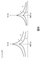
- FIG. 2 is an explanatory diagram of usable energy.
- the broken line indicated by reference numeral 700 represents an SOC-OCV curve showing the relationship between the SOC and the open circuit voltage (OCV) in each battery cell of the assembled battery 101.
- the solid line indicated by reference numeral 701 represents a discharge curve when each battery cell of the assembled battery 101 is discharged from the current SOC to SOC min with a constant discharge current I C0, DCh.
- the current SOC is shown by the broken line 703
- the SOC min is shown by the broken line 705.
- the discharge curve 701 shows the relationship between the SOC and the closed circuit voltage (CCV) at the time of discharge in each battery cell of the assembled battery 101. That is, the CCV of each battery cell when the assembled battery 101 is discharged is a dotted line 707 from the voltage value 704 corresponding to the current SOC to the voltage value 706 corresponding to the SOC min at the end of discharge according to the discharge curve 701. It changes continuously within the range not below the indicated minimum voltage V min.
- Ah rated represents the rated capacity of each battery cell.
- CCV (t) represents the CCV of each battery cell at time t, that is, the value of the discharge voltage, t present is the current time, and t end is the SOC of each battery reaching SOC min and discharging. It represents the time when it ended.
- This (Equation 1) represents the integral value of the discharge curve 701 from the current SOC to SOC min shown in FIG. That is, in FIG. 2, the area of the region 702 indicated by hatching surrounded by the discharge curve 701, the broken line 703, and the broken line 705 corresponds to the usable energy of each battery cell.
- the power storage system 1 when the power storage system 1 is mounted on an electric aircraft, it is necessary to calculate the usable energy of the assembled battery 101 in real time in order to realize safe control and an appropriate flight path.
- the calculation formula (Equation 1) assuming complete discharge with a constant discharge current I C0, DCh cannot be applied as it is.
- electric aircraft are sometimes used in low temperature environments such as 0 ° C or lower, but at low temperatures the behavior of the battery changes due to complex electrochemical reactions, so this point is also calculated on the premise of constant battery behavior.
- the equation (Equation 1) cannot be applied as it is. Therefore, in the present invention, the usable energy of the assembled battery 101 can be calculated in real time by the calculation method as described below.
- FIG. 3 is a diagram showing an example of an equivalent circuit model of a battery cell.
- the equivalent circuit of the battery cell shown in FIG. 3 is a parallel circuit of an open circuit voltage source 708, a DC resistance 709 having a resistance value Ro, a polarization capacity 710 having a capacitance value Cp, and a polarization resistance 711 having a resistance value Rp.
- the models are connected in series with each other. In this equivalent circuit, when the temperature of the battery cell is low, the resistance values Ro and Rp become very large.
- FIG. 4 is an explanatory diagram of usable energy at low temperature.
- the SOC-OCV curve 700 corresponds to that of FIG.
- the resistance values Ro and Rp of the DC resistance 709 and the polarization resistance 711 become larger in the equivalent circuit of the battery cell as described above, so that the discharge curve 701 is on the lower voltage side as a whole than in the state of FIG. 2 (Fig. 2). Shift downward).
- the discharge curve 701 reaches the minimum voltage V min at the SOC end , which is a SOC value larger than the SOC min described above.
- the SOC end is indicated by a broken line 712.
- the discharge curve 701 that changes at low temperature can be accurately predicted by the method described below.
- the usable energy of each battery cell has been described above, in the present embodiment, it is preferable to calculate the usable energy of the entire assembled battery 101.
- the usable energy of each battery cell constituting the assembled battery 101 is calculated for each battery cell, and the calculated usable energy of each battery cell is totaled to obtain the usable energy of the entire assembled battery 101. be able to.
- the usable energy may be calculated for each assembled battery 101 by applying the above calculation method to the entire assembled battery 101.
- FIG. 5 is a diagram showing a functional block of the battery management device 102 related to the usable energy calculation process according to the first embodiment of the present invention.
- the battery management device 102 of the present embodiment has each functional block of a battery state calculation unit 501, an internal parameter prediction unit 502, a discharge curve estimation unit 503, and a usable energy calculation unit 504. These functional blocks are realized, for example, by executing a predetermined program on a computer.
- the battery state calculation unit 501 acquires the current I, the closed circuit voltage CCV, and the battery temperature T cell detected when the assembled battery 101 is charging / discharging from the current sensor 103, the voltage sensor 105, and the temperature sensor 106, respectively. Then, based on this information, each state value of the charge state SOC representing the current state of the assembled battery 101 and the charge capacity decrease amount SOHQ is calculated. The details of the method of calculating these state values by the battery state calculation unit 501 will be described later with reference to FIG.
- the internal parameter prediction unit 502 acquires each state value of the assembled battery 101 calculated by the battery state calculation unit 501, that is, the charging state SOC and the charge capacity decrease amount SOHQ, and the battery temperature T of the assembled battery 101 is obtained from the temperature sensor 106. Obtain the cell and ambient temperature Tamb. Then, based on these acquired information, the DC resistance 709 and the polarization resistance 711 resistance values Ro, Rp and the open circuit voltage source 708 described with reference to FIG. 3 are used as parameters according to the internal state of the assembled battery 101 at each time point in the future. Predict the voltage value (open circuit voltage) OCV of.
- the internal parameter prediction unit 502 predicts these internal parameter values on the assumption that the assembled battery 101 is discharged at a predetermined discharge current I C0, DCh. The details of the method of predicting each internal parameter by the internal parameter prediction unit 502 will be described later with reference to FIG. 7.
- the discharge curve estimation unit 503 acquires each internal parameter value of the assembled battery 101 predicted by the internal parameter prediction unit 502. Then, by applying each acquired internal parameter value to the equivalent circuit model described with reference to FIG. 3, the voltage of the assembled battery 101 at each time point in the future is predicted, and the discharge curve 701 is estimated. The details of the method of estimating the discharge curve 701 by the discharge curve estimation unit 503 will be described later.
- the usable energy calculation unit 504 calculates the usable energy of the assembled battery 101 by applying the discharge curve 701 estimated by the discharge curve estimation unit 503 to the above-mentioned (Equation 1).
- the usable energy of the assembled battery 101 calculated by the battery management device 102 is transmitted from the battery management device 102 to the host controller 4, and is used for controlling the inverter 2. As a result, the usable energy of the assembled battery 101 is calculated in real time in the power storage system 1, and the charging / discharging control of the assembled battery 101 is performed.
- FIG. 6 is a diagram showing a functional block of the battery state calculation unit 501.
- the battery state calculation unit 501 includes a battery model unit 611 and a deterioration state detection unit 612.
- the battery model unit 611 stores a battery model that models the assembled battery 101, and uses this battery model to obtain the charge state SOC.
- the battery model in the battery model unit 611 is set according to, for example, the number of series connections and the number of parallel connections of the battery cells in the actual assembled battery 101, and the equivalent circuit of each battery cell shown in FIG.
- the battery model unit 611 applies the current I, the closed circuit voltage CCV, and the battery temperature T cell obtained from the current sensor 103, the voltage sensor 105, and the temperature sensor 106, respectively, to this battery model to obtain the state of the assembled battery 101. It is possible to obtain the charge state SOC according to the above.
- the voltage across the open circuit voltage source 708 corresponds to the open circuit voltage OCV
- the voltage across the parallel circuit of the polarization capacitance 710 and the polarization resistance 711 corresponds to the polarization voltage Vp.
- the values obtained by adding the applied voltage I ⁇ Ro of the DC resistance 709 and the polarization voltage Vp when the current I flows through this equivalent circuit to the open circuit voltage OCV correspond to the closed circuit voltage CCV.
- the value of each circuit constant in the equivalent circuit of FIG. 3 is determined according to the battery temperature T cell.
- the battery model unit 611 obtains the open circuit voltage OCV and the polarization voltage Vp for the entire assembled battery 101 from the current I, the closed circuit voltage CCV, and the battery temperature T cell, and further obtains the open circuit voltage OCV.
- the state of charge SOC can be obtained from the calculation result of.
- the deterioration state detection unit 612 detects the deterioration state of the assembled battery 101, and obtains the charge capacity reduction amount SOHQ according to the deterioration state.
- Each battery cell of the assembled battery 101 is deteriorated by repeating charging and discharging, and the charge capacity is reduced according to the deteriorated state.
- the deterioration state detection unit 612 stores, for example, information indicating the relationship between the current, voltage, and temperature of the assembled battery 101 and the deterioration state in advance, and by using this information, the current sensor 103, the voltage sensor 105, and the temperature
- the deterioration state of the assembled battery 101 is detected based on the current I, the closed circuit voltage CCV, and the battery temperature T cell obtained from the sensors 106, respectively. Then, based on the relationship between the deterioration state stored in advance and the charge capacity reduction amount SOHQ, the charge capacity reduction amount SOHQ corresponding to the detection result of the deterioration state of the assembled battery 101 can be obtained.
- FIG. 7 is a diagram showing a functional block of the internal parameter prediction unit 502.
- the internal parameter prediction unit 502 includes a temperature prediction unit 601, a SOC prediction unit 602, an electrochemical reaction model calculation unit 603, and an OCV prediction unit 604.
- the temperature predicting unit 601 the current and the battery temperature T cell and the ambient temperature T amb acquired from the temperature sensor 106, a constant discharge current I C0, DCh a preset is input.
- the temperature prediction unit 601 predicts the value of the battery temperature T cell at a future time point at a predetermined time interval starting from the present by solving a predetermined thermal energy balance equation based on the input information, and the value thereof is predicted. and outputs the prediction result as a temperature prediction value T predict.
- a predetermined thermal energy balance equation which is expressed by the following equation (2), it is possible to calculate the temperature prediction value T predict.
- Equation 2 is known as Bernardi's equation, and for example, Reference 1 (D. Bernardi et al., “A general energy balance for battery systems”, Journal of the Electrochemical Society, 132 (1), 5-12 (1985)).
- Equation 2 m is the weight of the assembled battery 101, c is the specific heat capacity, h is the heat transfer coefficient, and A is the surface area of the assembled battery 101. Further, Ro represents the resistance value of the DC resistance 709, and Vp represents the polarization voltage applied to the parallel circuit of the polarization capacitance 710 and the polarization resistance 711. Note that (Equation 2) is a differential equation, and discretization can be used as necessary when solving it.
- the SOC prediction unit 602 the current charge state SOC of the assembled battery 101 calculated by the battery state calculation unit 501, the charge capacity reduction amount SOHQ, and the preset constant discharge currents I C0, DCh are input. .. Based on these input information, the SOC prediction unit 602 predicts the value of the charge state SOC at each time point in the future at predetermined time intervals starting from the present, and the prediction result is the charge state prediction value SOC predict. Is output as.
- the discharge current I C0, DCh it is possible to calculate the state of charge estimated value SOC predict when it is constant.
- Electrochemical reaction model calculating unit 603, based on the temperature estimated value T predict and state of charge estimated value SOC predict the temperature predicting unit 601 and SOC estimation unit 602 is calculated, the future predetermined time intervals the current starting resistance Ro of the polarization resistance 711 and the DC resistance 709 at each time point, to predict Rp, and outputs the prediction result resistance predicted value Ro predict, as Rp predict.
- the resistance predicted value Ro predict it is possible to calculate the Rp predict.
- the resistance predicted value Ro predict the electrochemical reaction model computing unit 603, a time range Delta] t prediction for calculating the Rp predict may be set to the same value as calculated time range of the state of charge estimated value SOC predict by SOC estimating unit 602 Can be done.
- OCV prediction unit 604 based on the state of charge estimated value SOC predict the SOC estimation unit 602 is calculated, the voltage value of the open voltage source 708 of the current at the future each time point for each predetermined time interval, starting from (open circuit voltage ) predicts OCV, and outputs the prediction result OCV estimated value OCV predict.
- OCV map information preset, it is possible to obtain the OCV estimated value OCV predict corresponding to state of charge estimated value SOC predict.
- the OCV map information is information showing the relationship between SOC and OCV in the assembled battery 101, and is preset based on the characteristic information of the assembled battery 101 measured at the time of manufacture.
- Internal parameter prediction unit 502 the respective functional blocks described above, as a prediction result of the internal parameter according to the state of the future of the assembled battery 101, the resistance predicted value Ro predict, it is obtained Rp predict and OCV estimated value OCV predict can.
- the details of the electrochemical reaction model calculation unit 603 in the internal parameter prediction unit 502 will be described below.
- the Butler-Volmer phenomenon occurs inside the assembled battery 101.
- the resistance values Ro and Rp of the DC resistance 709 and the polarization resistance 711 have high current dependence, respectively.
- FIG. 8 is a diagram showing an example of the current dependence of the internal resistance at a low temperature.
- the curves of reference numerals 713 and 714 show an example of the relationship between the current of the DC resistance 709 and the resistance value Ro at the temperatures T1 and T2, and the curves of the reference numerals 715 and 716 are shown at the temperatures T1 and T2.
- An example of the relationship between the current of the polarization resistance 711 and the resistance value Rp is shown.
- the temperatures T1 and T2 are both low temperatures of less than 0 ° C., and T1 ⁇ T2.
- the resistance value at low temperature is determined by the following (Equation 3) and (Equation 4), which are functions of the charge state SOC, the temperature T, and the current I of the assembled battery 101. Predicted values of Ro and Rp Ro predict and Rp predict are calculated respectively. Note that (Equation 3) and (Equation 4) are arithmetic expressions called Butler-Volmer equations, which represent the electrochemical reaction inside the battery at a low temperature as shown in FIG.
- the curve 713 in FIG. 8 represents the resistance value Ro of the DC resistance 709 calculated by (Equation 3) for a specific combination of SOC and temperature T1.
- the curve 714 in FIG. 8 represents the resistance value Ro of the DC resistance 709 calculated by (Equation 3) for a temperature T2 higher than T1 at the same SOC.
- the curves 715 and 716 in FIG. 8 represent the resistance value Rp of the polarization resistance 711 calculated by (Equation 4) for a specific combination of SOC and temperatures T1 and T2, respectively.
- the parameter values of V o, map , I o, map , R SEI, and map in (Equation 3) and the parameter values of V ⁇ o, map , I ⁇ o, map in (Equation 4) are in the state of charge.
- the SOC and the temperature T are each determined according to the characteristics of the assembled battery 101. Therefore, in the electrochemical reaction model calculation unit 603, a map showing the relationship between the charge state SOC and the temperature T and each parameter value for various combinations of the charge state SOC and the temperature T that the assembled battery 101 can take in the power storage system 1. Store the information in advance.
- the electrochemical reaction model calculating unit 603 is able to identify each parameter value corresponding to the temperature prediction value T predict state of charge predicted value SOC predict at each time in the future. Then, each parameter value identified (Formula 3), it is possible to calculate the By applying the equation (4), the resistance value Ro of the DC resistance 709 and polarization resistance 711, the predicted value Ro predict for Rp, Rp predict ..
- V ⁇ o of V o (Equation 3), the map (Equation 4), map represents the surface overvoltage of the battery pack 101, respectively
- I o (Equation 3), the map (Equation 4) I ⁇ o, map represent the exchange current of the assembled battery 101, respectively.
- the R SEI and map of (Equation 3) represent the resistance component due to the SEI (Solid Electrolyte Interphase) formed in the assembled battery 101.
- FIG. 9 is a diagram showing a functional block of the electrochemical reaction model calculation unit 603 according to the first embodiment of the present invention.
- the electrochemical reaction model calculation unit 603 includes a DC resistance parameter map 801 and a DC resistance value prediction unit 802, a polarization resistance parameter map 803, and a polarization resistance value prediction unit 804.
- the parameter map 801 for DC resistance includes the Vo, map , I o, map , R SEI, and map parameters of (Equation 3) relating to the temperature T and charge state SOC of the assembled battery 101 and the resistance value Ro of the DC resistance 709. Map information that represents the relationship with the value. For example, the map information preset based on the characteristic information of the assembled battery 101 measured at the time of manufacture is stored in the electrochemical reaction model calculation unit 603 as the DC resistance parameter map 801.
- the temperature prediction value T predict at each time point in the time range Delta] t prediction state of charge predicted value SOC predict are input .
- the DC resistance parameter map 801 identifies each parameter value of (Equation 3) corresponding to the combination of the input temperature prediction value T predict and the charge state prediction value SOC predict at each time point by map search, and DC resistance. Output to the value prediction unit 802.
- the DC resistance value prediction unit 802 performs the calculation of (Equation 3) using the parameter value input from the DC resistance parameter map 801 to obtain the resistance value Ro of the DC resistance 709 at each time point in the time range ⁇ t prediction. Is predicted, and the prediction result is output as the resistance prediction value Ro predict.
- the parameter map 803 for polarization resistance includes the temperature T and charge state SOC of the assembled battery 101, and the parameter values of V to o, map , I to o, and map of the resistance value Rp of the polarization resistance 711. Map information that represents the relationship. Similar to the above-mentioned DC resistance parameter map 801, for example, the map information preset based on the characteristic information of the assembled battery 101 measured at the time of manufacture is used as the polarization resistance parameter map 803 in the electrochemical reaction model calculation unit. It is stored in 603.
- the polarization resistance parameter map 803 identifies each parameter value of (Equation 4) corresponding to the combination of the input temperature prediction value T predict and the charge state prediction value SOC predict at each time point by map search, and the polarization resistance. Output to the value prediction unit 804.
- the polarization resistance value prediction unit 804 performs the calculation of (Equation 4) using the parameter value input from the polarization resistance parameter map 803, and thereby performs the resistance value Rp of the polarization resistance 711 at each time point in the time range ⁇ t prediction. Is predicted, and the prediction result is output as the resistance prediction value Rp predict.
- the DC resistance parameter map 801 and the polarization resistance parameter map 803, which are correlation maps showing the relationship with each parameter value of (Equation 4) the inside of the assembled battery 101 for each future time point.
- the resistance values Ro and Rp of the DC resistance 709 and the polarization resistance 711, which are the parameters, can be predicted.
- Discharge curve estimating unit of FIG. 5 503 thus internal parameter calculated by an electrochemical reaction model computing unit 603 in the prediction unit 502 the resistance predicted value Ro predict, Rp predict and, OCV prediction value calculated by the OCV estimating unit 604 based on the predicted values of the internal parameters of the OCV predict, by using the equivalent circuit model of FIG. 3, it is possible to estimate the discharge curve 701 of FIG.
- the predictive value of these internal parameters by substituting the following equation (5), calculates the voltage predicted value V predict the prediction value of the closed circuit voltage CCV of the battery pack 101 at each time in the future. Then, plot the relationship between the obtained voltage estimated value V predict the state of charge estimated value SOC predict.
- the discharge curve 701 when the assembled battery 101 is discharged from the current SOC to the SOC end in FIG. 4 is reflected in the prediction results of the DC resistance 709 and the resistance values Ro and Rp of the polarization resistance 711 at low temperature.
- the estimation result can be obtained.
- ⁇ represents the time constant of the polarization circuit composed of the parallel circuit of the polarization capacitance 710 and the polarization resistance 711 in FIG.
- the value of this time constant ⁇ is preset based on the characteristic information of the assembled battery 101 measured at the time of manufacture and the like.
- the usable energy calculation unit 504 specifies the value of SOC whose predicted voltage value V predict is less than a predetermined minimum voltage V min as the SOC end based on the discharge curve 701 estimated by the discharge curve estimation unit 503. Then, the usable energy of the assembled battery 101 can be calculated by the above-mentioned (Equation 1).
- the battery management device 102 is a device that manages the rechargeable and dischargeable assembled battery 101, and has an internal parameter prediction unit 502 that predicts internal parameters according to the state of the assembled battery 101 in the future, and an internal parameter prediction unit. Based on the discharge curve estimation unit 503 that estimates the discharge curve 701 that represents the change in the discharge voltage from the current charge state to the minimum charge state of the assembled battery 101 based on the internal parameters predicted by the 502, and the discharge curve 701. It is provided with a usable energy calculation unit 504 for calculating the usable energy of the assembled battery 101.
- the internal parameter prediction unit 502 uses a correlation map showing the relationship between the temperature T and charge state SOC of the assembled battery 101 and the parameter values of the Butler-Bolmer equations of (Equation 3) and (Equation 4), and the assembled battery 101.
- the resistance values Ro and Rp of the DC resistance 709 and the polarization resistance 711, which are the internal parameters of the above, are predicted. Since this is done, the usable energy of the assembled battery 101 at a low temperature can be accurately estimated.
- the temperature prediction value T predict future battery pack 101 Future charging of the assembled battery 101 based on the calculated temperature prediction unit 601 and the charge capacity reduction amount SOHQ indicating the current charging state SOC of the assembled battery 101 and the deteriorated state of the assembled battery 101 and the discharge current I C0, DCh.
- SOC (state of charge) prediction unit 602 that calculates a state estimated value SOC predict, using a correlation map of the foregoing based upon the temperature prediction value T predict and state of charge predicted value SOC predict, which is an internal parameter of the assembled battery 101 DC resistance It has a 709 and an electrochemical reaction model calculation unit 603 for predicting the resistance values Ro and Rp of the polarization resistance 711. Since this is done, it is possible to accurately predict the internal parameters according to the state of the assembled battery 101 in the future.
- the internal parameters include the DC resistance value Ro and the polarization resistance value Rp of the assembled battery 101.
- the correlation map is for DC resistance showing the relationship between the temperature T and charge state SOC of the assembled battery 101 and the parameter values V o, map , I o, map , R SEI, map of the Butler-Volmer equation regarding the DC resistance value Ro.
- Parameter map 801 and parameter map for polarization resistance showing the relationship between the temperature T and charge state SOC of the assembled battery 101 and the parameter values V ⁇ o, map , I ⁇ o, map of the Butler-Volmer equation regarding the polarization resistance value Rp. 803 and is included.
- the internal parameters further include the open circuit voltage OCV of the assembled battery 101.
- Internal parameter prediction unit 502 further includes a OCV (open circuit voltage) prediction unit 604 that predicts the open circuit voltage OCV corresponding to the state of the future of the battery pack 101 based on the state of charge estimated value SOC predict. Therefore, as internal parameters necessary for estimating the discharge curve 701, the open circuit voltage OCV can be further predicted in addition to the DC resistance value Ro and the polarization resistance value Rp.
- OCV open circuit voltage
- the battery management device 102 includes a battery state calculation unit 501 that calculates the charge state SOC and the deterioration state (charge capacity decrease amount) SOHQ of the current assembled battery 101.
- the internal parameter prediction unit 502 predicts internal parameters based on the current temperature T cell and ambient temperature Tamb of the assembled battery 101, and the charge state SOC and deterioration state SOHQ calculated by the battery state calculation unit 501. By doing so, it is possible to surely acquire the information necessary for predicting the internal parameters.
- the resistance values Ro and Rp of the DC resistance 709 and the polarization resistance 711 gradually increase as the deterioration progresses with the passage of use time. Therefore, in order to improve the prediction accuracy of the usable energy over time, the parameter map 801 for DC resistance and the parameter map 803 for polarization resistance are appropriately updated in the electrochemical reaction model calculation unit 603 in the internal parameter prediction unit 502. There is a need to.
- FIG. 10 is a diagram showing a functional block of the electrochemical reaction model calculation unit 603 according to the second embodiment of the present invention.
- the electrochemical reaction model calculation unit 603 includes the DC resistance parameter map 801 and the DC resistance value prediction unit 802, the polarization resistance parameter map 803 and the polarization resistance value prediction unit 804 described in the first embodiment.
- a map update unit 810 is further provided.
- the map update unit 810 has an internal parameter calculation unit 805, a data storage unit 806, and an electrochemical reaction model application unit 807.
- the internal parameter calculation unit 805 acquires the current I, the closed circuit voltage CCV, and the battery temperature T cell detected when the assembled battery 101 is charging / discharging from the current sensor 103, the voltage sensor 105, and the temperature sensor 106, respectively.
- the internal parameter calculation unit 805 has a Kalman filter of a state space model that reflects the characteristics of the assembled battery 101, and using this Kalman filter, the resistance values of the DC resistance 709 and the polarization resistance 711 during charging and discharging of the assembled battery 101. Calculate Ro and Rp. If the resistance values Ro and Rp of the DC resistance 709 and the polarization resistance 711 can be appropriately calculated, these may be obtained by a method other than the Kalman filter calculation.
- the data storage unit 806 charges the DC resistance 709 and the resistance values Ro and Rp of the polarization resistance 711 calculated by the internal parameter calculation unit 805 at a low temperature when the temperature of the assembled battery 101 is equal to or lower than a predetermined value. Stores the state SOC, current I, and temperature T in association with each other. As a result, every time the assembled battery 101 is used in a low temperature state, data representing the relationship between the charge state SOC, the current I and the temperature T and the resistance values Ro and Rp at that time is accumulated in the data storage unit 806. ..
- the electrochemical reaction model application unit 807 applies the data to the above-mentioned (Equation 3) and (Equation 4), respectively, to obtain the charging state SOC and the charging state SOC. Relationship between temperature T and each parameter value V o, map , I o, map , R SEI, map of (Equation 3) and each parameter value V ⁇ o, map , I ⁇ o, map of (Equation 4) get. Then, based on these acquired relationships, the DC resistance parameter map 801 and the polarization resistance parameter map 803 are updated.
- the DC resistance parameter is changed according to the change in the internal state due to the deterioration progress of the assembled battery 101.
- the map 801 and the parameter map 803 for polarization resistance can be updated.
- the battery management device 102 calculates the resistance values Ro and Rp of the DC resistance 709 and the polarization resistance 711 as internal parameters according to the current state of the assembled battery 101. Then, based on these calculated internal parameters, a correlation map (DC) showing the relationship between the temperature T and charge state SOC of the assembled battery 101 and the parameter values of the Butler-Bolmer equations of (Equation 3) and (Equation 4).
- a map update unit 810 for updating the resistance parameter map 801 and the polarization resistance parameter map 803) is provided. Since this is done, the correlation map can be updated as appropriate to improve the accuracy of predicting available energy.
Landscapes
- Physics & Mathematics (AREA)
- General Physics & Mathematics (AREA)
- Engineering & Computer Science (AREA)
- Manufacturing & Machinery (AREA)
- Chemical & Material Sciences (AREA)
- Chemical Kinetics & Catalysis (AREA)
- Electrochemistry (AREA)
- General Chemical & Material Sciences (AREA)
- Power Engineering (AREA)
- Secondary Cells (AREA)
- Tests Of Electric Status Of Batteries (AREA)
- Charge And Discharge Circuits For Batteries Or The Like (AREA)
Priority Applications (1)
| Application Number | Priority Date | Filing Date | Title |
|---|---|---|---|
| JP2022536144A JP7389258B2 (ja) | 2020-07-16 | 2021-05-07 | 電池管理装置、電池管理方法、電力貯蔵システム |
Applications Claiming Priority (2)
| Application Number | Priority Date | Filing Date | Title |
|---|---|---|---|
| JP2020122382 | 2020-07-16 | ||
| JP2020-122382 | 2020-07-16 |
Publications (1)
| Publication Number | Publication Date |
|---|---|
| WO2022014124A1 true WO2022014124A1 (ja) | 2022-01-20 |
Family
ID=79554673
Family Applications (1)
| Application Number | Title | Priority Date | Filing Date |
|---|---|---|---|
| PCT/JP2021/017554 Ceased WO2022014124A1 (ja) | 2020-07-16 | 2021-05-07 | 電池管理装置、電池管理方法、電力貯蔵システム |
Country Status (2)
| Country | Link |
|---|---|
| JP (1) | JP7389258B2 (https=) |
| WO (1) | WO2022014124A1 (https=) |
Cited By (3)
| Publication number | Priority date | Publication date | Assignee | Title |
|---|---|---|---|---|
| JP7317247B1 (ja) * | 2022-06-10 | 2023-07-28 | 三菱電機株式会社 | 並列電池管理装置および並列電池制御システム |
| CN116660752A (zh) * | 2023-05-29 | 2023-08-29 | 广州汽车集团股份有限公司 | 电池界面反应电压修正方法、装置、可读介质及电子设备 |
| CN118659050A (zh) * | 2024-07-08 | 2024-09-17 | 无锡广盈集团有限公司 | 一种储能soc均衡控制策略优化方法 |
Families Citing this family (2)
| Publication number | Priority date | Publication date | Assignee | Title |
|---|---|---|---|---|
| WO2026048525A1 (ja) * | 2024-08-29 | 2026-03-05 | パナソニックIpマネジメント株式会社 | 電池分析システム、電池分析方法および電池分析プログラム |
| WO2026048524A1 (ja) * | 2024-08-29 | 2026-03-05 | パナソニックIpマネジメント株式会社 | 電池分析システム、電池分析方法および電池分析プログラム |
Citations (8)
| Publication number | Priority date | Publication date | Assignee | Title |
|---|---|---|---|---|
| JP2011041441A (ja) * | 2009-08-18 | 2011-02-24 | Toyota Central R&D Labs Inc | 充電電力制限値演算装置 |
| JP2016126999A (ja) * | 2014-12-26 | 2016-07-11 | 株式会社デンソー | 電池電力予測装置 |
| JP2016173281A (ja) * | 2015-03-17 | 2016-09-29 | 株式会社デンソー | 電池エネルギ予測装置 |
| JP2017138128A (ja) * | 2016-02-01 | 2017-08-10 | 株式会社デンソー | 電池状態推定装置 |
| US20180059190A1 (en) * | 2016-08-25 | 2018-03-01 | GM Global Technology Operations LLC | State estimation of an energy system |
| JP2019100897A (ja) * | 2017-12-05 | 2019-06-24 | 日立化成株式会社 | デバイス状態検知装置、電源システムおよび自動車 |
| JP2020041949A (ja) * | 2018-09-12 | 2020-03-19 | 株式会社東芝 | 電池状態推定装置、電池状態推定方法、プログラム、制御回路及び蓄電システム |
| JP2020047587A (ja) * | 2018-09-14 | 2020-03-26 | トヨタ自動車株式会社 | 二次電池システムおよび二次電池の内部状態推定方法 |
-
2021
- 2021-05-07 WO PCT/JP2021/017554 patent/WO2022014124A1/ja not_active Ceased
- 2021-05-07 JP JP2022536144A patent/JP7389258B2/ja active Active
Patent Citations (8)
| Publication number | Priority date | Publication date | Assignee | Title |
|---|---|---|---|---|
| JP2011041441A (ja) * | 2009-08-18 | 2011-02-24 | Toyota Central R&D Labs Inc | 充電電力制限値演算装置 |
| JP2016126999A (ja) * | 2014-12-26 | 2016-07-11 | 株式会社デンソー | 電池電力予測装置 |
| JP2016173281A (ja) * | 2015-03-17 | 2016-09-29 | 株式会社デンソー | 電池エネルギ予測装置 |
| JP2017138128A (ja) * | 2016-02-01 | 2017-08-10 | 株式会社デンソー | 電池状態推定装置 |
| US20180059190A1 (en) * | 2016-08-25 | 2018-03-01 | GM Global Technology Operations LLC | State estimation of an energy system |
| JP2019100897A (ja) * | 2017-12-05 | 2019-06-24 | 日立化成株式会社 | デバイス状態検知装置、電源システムおよび自動車 |
| JP2020041949A (ja) * | 2018-09-12 | 2020-03-19 | 株式会社東芝 | 電池状態推定装置、電池状態推定方法、プログラム、制御回路及び蓄電システム |
| JP2020047587A (ja) * | 2018-09-14 | 2020-03-26 | トヨタ自動車株式会社 | 二次電池システムおよび二次電池の内部状態推定方法 |
Cited By (4)
| Publication number | Priority date | Publication date | Assignee | Title |
|---|---|---|---|---|
| JP7317247B1 (ja) * | 2022-06-10 | 2023-07-28 | 三菱電機株式会社 | 並列電池管理装置および並列電池制御システム |
| CN116660752A (zh) * | 2023-05-29 | 2023-08-29 | 广州汽车集团股份有限公司 | 电池界面反应电压修正方法、装置、可读介质及电子设备 |
| CN116660752B (zh) * | 2023-05-29 | 2024-03-19 | 广州汽车集团股份有限公司 | 电池界面反应电压修正方法、装置、可读介质及电子设备 |
| CN118659050A (zh) * | 2024-07-08 | 2024-09-17 | 无锡广盈集团有限公司 | 一种储能soc均衡控制策略优化方法 |
Also Published As
| Publication number | Publication date |
|---|---|
| JPWO2022014124A1 (https=) | 2022-01-20 |
| JP7389258B2 (ja) | 2023-11-29 |
Similar Documents
| Publication | Publication Date | Title |
|---|---|---|
| JP7389258B2 (ja) | 電池管理装置、電池管理方法、電力貯蔵システム | |
| Kumar et al. | Advances in batteries, battery modeling, battery management system, battery thermal management, SOC, SOH, and charge/discharge characteristics in EV applications | |
| JP7201792B2 (ja) | 電池管理装置、電池管理方法、電力貯蔵システム | |
| Tarhan et al. | Hybrid battery management system design for electric aircraft | |
| CN103502829B (zh) | 用于电化学存储系统热管理的优化方法 | |
| US10345385B2 (en) | Battery state estimation systems and methods using a nonlinear resistance element | |
| EP1798100B1 (en) | Battery management system | |
| JP7066390B2 (ja) | 蓄電池の経済性推定装置および経済性推定方法 | |
| CN100547849C (zh) | 估计电池充电状态的方法、电池管理系统及其驱动方法 | |
| CN101013822B (zh) | 用于补偿电池充电状态的方法和使用该方法的电池管理系统 | |
| JP7231657B2 (ja) | 電池制御装置 | |
| CN113325316A (zh) | 信息计算系统和信息计算方法 | |
| US20100121587A1 (en) | Health Management of Rechargeable Batteries | |
| JP7381617B2 (ja) | 電池管理装置、電池管理方法、電力貯蔵システム | |
| KR102448627B1 (ko) | 차량용 배터리 충전 상태(soc) 추정 장치 및 방법 | |
| US20150197164A1 (en) | Receding horizon regression analysis for battery impedance parameter estimation | |
| JP2022547751A (ja) | バッテリの充放電特性を用いてバッテリに電気エネルギーを蓄えるためのエネルギー貯蔵システム(ess) | |
| US20140239914A1 (en) | Battery controller | |
| CN107533109A (zh) | 电池控制装置以及电动车辆系统 | |
| KR102101002B1 (ko) | 배터리 수명 예측 방법 | |
| KR101329915B1 (ko) | 하이브리드 전기 자동차용 배터리의 주행 중 최대 출력파워 예측 방법 및 장치 | |
| KR20170084607A (ko) | 배터리 관리 장치 및 방법 | |
| Fuller | A battery model for constant-power discharge including rate effects | |
| Hashemi et al. | New intelligent battery management system for drones | |
| JPWO2022014124A5 (https=) |
Legal Events
| Date | Code | Title | Description |
|---|---|---|---|
| 121 | Ep: the epo has been informed by wipo that ep was designated in this application |
Ref document number: 21841799 Country of ref document: EP Kind code of ref document: A1 |
|
| ENP | Entry into the national phase |
Ref document number: 2022536144 Country of ref document: JP Kind code of ref document: A |
|
| NENP | Non-entry into the national phase |
Ref country code: DE |
|
| 122 | Ep: pct application non-entry in european phase |
Ref document number: 21841799 Country of ref document: EP Kind code of ref document: A1 |