WO2022014019A1 - 検査システム、判定処理装置、及び検査方法 - Google Patents
検査システム、判定処理装置、及び検査方法 Download PDFInfo
- Publication number
- WO2022014019A1 WO2022014019A1 PCT/JP2020/027719 JP2020027719W WO2022014019A1 WO 2022014019 A1 WO2022014019 A1 WO 2022014019A1 JP 2020027719 W JP2020027719 W JP 2020027719W WO 2022014019 A1 WO2022014019 A1 WO 2022014019A1
- Authority
- WO
- WIPO (PCT)
- Prior art keywords
- data
- radiation
- determination
- flaw
- image data
- Prior art date
- Legal status (The legal status is an assumption and is not a legal conclusion. Google has not performed a legal analysis and makes no representation as to the accuracy of the status listed.)
- Ceased
Links
Images



Classifications
-
- G—PHYSICS
- G01—MEASURING; TESTING
- G01N—INVESTIGATING OR ANALYSING MATERIALS BY DETERMINING THEIR CHEMICAL OR PHYSICAL PROPERTIES
- G01N23/00—Investigating or analysing materials by the use of wave or particle radiation, e.g. X-rays or neutrons, not covered by groups G01N3/00 – G01N17/00, G01N21/00 or G01N22/00
- G01N23/02—Investigating or analysing materials by the use of wave or particle radiation, e.g. X-rays or neutrons, not covered by groups G01N3/00 – G01N17/00, G01N21/00 or G01N22/00 by transmitting the radiation through the material
- G01N23/04—Investigating or analysing materials by the use of wave or particle radiation, e.g. X-rays or neutrons, not covered by groups G01N3/00 – G01N17/00, G01N21/00 or G01N22/00 by transmitting the radiation through the material and forming images of the material
-
- G—PHYSICS
- G01—MEASURING; TESTING
- G01N—INVESTIGATING OR ANALYSING MATERIALS BY DETERMINING THEIR CHEMICAL OR PHYSICAL PROPERTIES
- G01N23/00—Investigating or analysing materials by the use of wave or particle radiation, e.g. X-rays or neutrons, not covered by groups G01N3/00 – G01N17/00, G01N21/00 or G01N22/00
- G01N23/02—Investigating or analysing materials by the use of wave or particle radiation, e.g. X-rays or neutrons, not covered by groups G01N3/00 – G01N17/00, G01N21/00 or G01N22/00 by transmitting the radiation through the material
- G01N23/06—Investigating or analysing materials by the use of wave or particle radiation, e.g. X-rays or neutrons, not covered by groups G01N3/00 – G01N17/00, G01N21/00 or G01N22/00 by transmitting the radiation through the material and measuring the absorption
- G01N23/083—Investigating or analysing materials by the use of wave or particle radiation, e.g. X-rays or neutrons, not covered by groups G01N3/00 – G01N17/00, G01N21/00 or G01N22/00 by transmitting the radiation through the material and measuring the absorption the radiation being X-rays
-
- G—PHYSICS
- G01—MEASURING; TESTING
- G01N—INVESTIGATING OR ANALYSING MATERIALS BY DETERMINING THEIR CHEMICAL OR PHYSICAL PROPERTIES
- G01N23/00—Investigating or analysing materials by the use of wave or particle radiation, e.g. X-rays or neutrons, not covered by groups G01N3/00 – G01N17/00, G01N21/00 or G01N22/00
- G01N23/02—Investigating or analysing materials by the use of wave or particle radiation, e.g. X-rays or neutrons, not covered by groups G01N3/00 – G01N17/00, G01N21/00 or G01N22/00 by transmitting the radiation through the material
- G01N23/06—Investigating or analysing materials by the use of wave or particle radiation, e.g. X-rays or neutrons, not covered by groups G01N3/00 – G01N17/00, G01N21/00 or G01N22/00 by transmitting the radiation through the material and measuring the absorption
- G01N23/18—Investigating the presence of flaws defects or foreign matter
-
- G—PHYSICS
- G01—MEASURING; TESTING
- G01N—INVESTIGATING OR ANALYSING MATERIALS BY DETERMINING THEIR CHEMICAL OR PHYSICAL PROPERTIES
- G01N33/00—Investigating or analysing materials by specific methods not covered by groups G01N1/00 - G01N31/00
- G01N33/20—Metals
- G01N33/204—Structure thereof, e.g. crystal structure
- G01N33/2045—Defects
-
- G—PHYSICS
- G01—MEASURING; TESTING
- G01N—INVESTIGATING OR ANALYSING MATERIALS BY DETERMINING THEIR CHEMICAL OR PHYSICAL PROPERTIES
- G01N33/00—Investigating or analysing materials by specific methods not covered by groups G01N1/00 - G01N31/00
- G01N33/20—Metals
- G01N33/207—Welded or soldered joints; Solderability
-
- G—PHYSICS
- G06—COMPUTING OR CALCULATING; COUNTING
- G06T—IMAGE DATA PROCESSING OR GENERATION, IN GENERAL
- G06T7/00—Image analysis
- G06T7/0002—Inspection of images, e.g. flaw detection
- G06T7/0004—Industrial image inspection
-
- G—PHYSICS
- G06—COMPUTING OR CALCULATING; COUNTING
- G06T—IMAGE DATA PROCESSING OR GENERATION, IN GENERAL
- G06T7/00—Image analysis
- G06T7/0002—Inspection of images, e.g. flaw detection
- G06T7/0004—Industrial image inspection
- G06T7/001—Industrial image inspection using an image reference approach
-
- G—PHYSICS
- G01—MEASURING; TESTING
- G01N—INVESTIGATING OR ANALYSING MATERIALS BY DETERMINING THEIR CHEMICAL OR PHYSICAL PROPERTIES
- G01N2223/00—Investigating materials by wave or particle radiation
- G01N2223/03—Investigating materials by wave or particle radiation by transmission
- G01N2223/04—Investigating materials by wave or particle radiation by transmission and measuring absorption
-
- G—PHYSICS
- G01—MEASURING; TESTING
- G01N—INVESTIGATING OR ANALYSING MATERIALS BY DETERMINING THEIR CHEMICAL OR PHYSICAL PROPERTIES
- G01N2223/00—Investigating materials by wave or particle radiation
- G01N2223/30—Accessories, mechanical or electrical features
- G01N2223/33—Accessories, mechanical or electrical features scanning, i.e. relative motion for measurement of successive object-parts
- G01N2223/3303—Accessories, mechanical or electrical features scanning, i.e. relative motion for measurement of successive object-parts object fixed; source and detector move
-
- G—PHYSICS
- G01—MEASURING; TESTING
- G01N—INVESTIGATING OR ANALYSING MATERIALS BY DETERMINING THEIR CHEMICAL OR PHYSICAL PROPERTIES
- G01N2223/00—Investigating materials by wave or particle radiation
- G01N2223/40—Imaging
- G01N2223/401—Imaging image processing
-
- G—PHYSICS
- G01—MEASURING; TESTING
- G01N—INVESTIGATING OR ANALYSING MATERIALS BY DETERMINING THEIR CHEMICAL OR PHYSICAL PROPERTIES
- G01N2223/00—Investigating materials by wave or particle radiation
- G01N2223/60—Specific applications or type of materials
- G01N2223/628—Specific applications or type of materials tubes, pipes
-
- G—PHYSICS
- G01—MEASURING; TESTING
- G01N—INVESTIGATING OR ANALYSING MATERIALS BY DETERMINING THEIR CHEMICAL OR PHYSICAL PROPERTIES
- G01N2223/00—Investigating materials by wave or particle radiation
- G01N2223/60—Specific applications or type of materials
- G01N2223/629—Specific applications or type of materials welds, bonds, sealing compounds
-
- G—PHYSICS
- G01—MEASURING; TESTING
- G01N—INVESTIGATING OR ANALYSING MATERIALS BY DETERMINING THEIR CHEMICAL OR PHYSICAL PROPERTIES
- G01N2223/00—Investigating materials by wave or particle radiation
- G01N2223/60—Specific applications or type of materials
- G01N2223/646—Specific applications or type of materials flaws, defects
-
- G—PHYSICS
- G06—COMPUTING OR CALCULATING; COUNTING
- G06T—IMAGE DATA PROCESSING OR GENERATION, IN GENERAL
- G06T2207/00—Indexing scheme for image analysis or image enhancement
- G06T2207/10—Image acquisition modality
- G06T2207/10116—X-ray image
-
- G—PHYSICS
- G06—COMPUTING OR CALCULATING; COUNTING
- G06T—IMAGE DATA PROCESSING OR GENERATION, IN GENERAL
- G06T2207/00—Indexing scheme for image analysis or image enhancement
- G06T2207/20—Special algorithmic details
- G06T2207/20081—Training; Learning
-
- G—PHYSICS
- G06—COMPUTING OR CALCULATING; COUNTING
- G06T—IMAGE DATA PROCESSING OR GENERATION, IN GENERAL
- G06T2207/00—Indexing scheme for image analysis or image enhancement
- G06T2207/20—Special algorithmic details
- G06T2207/20212—Image combination
-
- G—PHYSICS
- G06—COMPUTING OR CALCULATING; COUNTING
- G06T—IMAGE DATA PROCESSING OR GENERATION, IN GENERAL
- G06T2207/00—Indexing scheme for image analysis or image enhancement
- G06T2207/30—Subject of image; Context of image processing
- G06T2207/30108—Industrial image inspection
- G06T2207/30136—Metal
-
- G—PHYSICS
- G06—COMPUTING OR CALCULATING; COUNTING
- G06T—IMAGE DATA PROCESSING OR GENERATION, IN GENERAL
- G06T2207/00—Indexing scheme for image analysis or image enhancement
- G06T2207/30—Subject of image; Context of image processing
- G06T2207/30108—Industrial image inspection
- G06T2207/30152—Solder
Definitions
- the present invention relates to a technique for performing non-destructive inspection of welded portions of pipes.
- Plants that process fluids include natural gas plants that liquefy natural gas, separate and recover natural gas liquids, petroleum refining plants that distill and desulfurize crude oil and various intermediate products, petroleum chemical products and intermediate chemicals. There are chemical plants that produce products and polymers. These plants have a structure in which a large number of equipment groups such as static equipment such as tower tanks and heat exchangers and dynamic equipment such as pumps are arranged. A pipe for exchanging fluid is connected between the devices constituting these device groups.
- welding may be used to connect the pipes to each other and to connect the pipes to pipe members such as flanges and elbows. It is said that the welded part contains flaws of a size or shape that exceeds the permissible degree (hereinafter, harmful flaws that exceed the permissible extent and are judged to be rejected are referred to as "defects"). After operating the plant, it becomes a factor that causes troubles such as fluid leakage and breakage of welded parts. Therefore, after the pipe or the pipe member is welded, a plurality of factors such as the fluid and pressure to which the pipe or the pipe member is exposed are added in order to determine whether or not the pipe welded portion contains a defect.
- the radiation transmission test is performed according to the sampling frequency set in the above.
- the imaging of the welded portion using radiation is an operation that requires ensuring a safe distance
- the number of imaging operations that can be performed simultaneously in a limited construction area is limited.
- it takes time to set up each shooting site it is necessary to consider the effect on the entire construction schedule of the plant.
- the number of welded parts to be welded when constructing a plant is enormous, labor for handling a large amount of film according to the number of welded parts is also required.
- it is necessary to manage and dispose of the developer that develops the film it is also necessary to consider the environment. In order to solve these various problems, it is required to establish a welded portion inspection technique capable of improving work efficiency and further reducing the burden on the operator.
- Patent Document 1 describes a radiation inspection device that irradiates a pipe of a subject from a radiation source in a pipe of a plant, detects the transmitted radiation with a detector, and inspects the wall thickness of the pipe of the subject. ing. Further, a configuration is described in which a transmission image is acquired at different rotation angles by rotating the angle between the radiation source for the pipe and the detector. Further, in Patent Document 2, the wall thinning depth of the structure of the plant is measured, the standardized constant is obtained from the measured value, and the structure is obtained for each combination of a predetermined usage period and the plate thickness based on the standardized constant. A maintenance support device that calculates the probability that an object will become unusable is described. As described above, conventionally, the method of detecting the amount of radiation transmitted without using a film has only been used for thinning control of piping in an operating plant.
- the present invention provides a technique for improving the work efficiency of a radiation transmission test and improving the inspection accuracy by reducing the burden on the operator in the non-destructive inspection of defects in the welded portion of the pipe or the pipe member.
- the inspection system of the present invention is an inspection system for non-destructive inspection of defects in welds of pipes or pipe members.
- An imaging data acquisition unit that acquires imaging data obtained by transmitting radiation through the welded portion of the pipe or piping member to be inspected, and an imaging data acquisition unit.
- Judgment processing unit to be performed and It is characterized by being equipped with.
- the inspection system may also have the following features.
- (A) The image pickup data acquisition unit is arranged so as to face each other with the welded portion to be inspected interposed therebetween, and detects a radiation irradiation portion that irradiates the welded portion with radiation and radiation transmitted through the welded portion. To acquire the imaging data as digital data based on the transmission intensity of the radiation detected by the detector.
- the image pickup data acquisition unit is A jig for arranging the radiation irradiation part and the detector facing each other across the welded part to be inspected, and By moving the radiation irradiation unit and the detection unit in the circumferential direction while synchronizing the radiation irradiation unit and the detection unit while maintaining the state of being arranged so as to face each other by the jig, the position of irradiating the radiation is moved in the circumferential direction. Equipped with a moving mechanism to move, Acquiring the imaging data at a plurality of positions in different circumferential directions of the welded portion.
- An image processing unit for creating the image data by combining a plurality of image pickup data acquired at a plurality of positions different in the circumferential direction of the welded portion along the circumferential direction is provided.
- D An analog image obtained by irradiating a region including a welded portion to be inspected with radiation and exposing the radiation image transmitted through the welded portion to a film is converted into a digital image, and the digital image is captured. It should be data.
- the determination data is associated with information that can identify the position of the flaw, the size of the flaw, and the shape feature of the flaw in the welding line included in the image data, and the welding result of the welded portion is regarded as a failure.
- the determination processing unit performs a process of associating the determination data with the image data by making a determination based on the provisional determination data associated with the image data by the automatic determination processing unit.
- the determination processing unit is configured so that the automatic determination unit can accept processing for modifying the provisional determination data associated with the image data.
- the determination processing device of the present invention is a determination processing device that performs a determination process relating to a non-destructive inspection of defects in a welded portion of a pipe or a piping member.
- Judgment data showing the result of determining a defect in the welded portion of the pipe to be inspected based on the distribution of the transmission intensity of the radiation obtained by transmitting radiation through the welded portion of the pipe or the pipe member to be inspected is the radiation. It is characterized in that it is configured to perform processing associated with image data indicating the distribution of transmission intensity of.
- the inspection method of the present invention is an inspection method relating to a non-destructive inspection of defects in a welded portion of a pipe or a pipe member.
- Judgment data showing the result of determining the defect of the welded portion to be inspected based on the distribution of the transmission intensity of the radiation obtained by transmitting radiation through the welded portion of the pipe or the pipe member to be inspected is transmitted by the radiation. It is characterized by including a step of performing a process of associating with image data showing an intensity distribution.
- the present invention has acquired imaging data obtained by transmitting radiation through the welded portion of the pipe or piping member to be inspected in the non-destructive inspection of defects in the welded portion of the pipe or piping member. Further, the image pickup data is used to determine a defect in the welded portion to be inspected, and the determination data indicating the determination result is associated with the image data indicating the distribution of the transmission intensity of the radiation. Therefore, the determination result of the welded portion can be obtained without using a film, and the work efficiency of the radiation transmission test can be improved by reducing the burden on the operator. Further, by using the image data, the inspection accuracy and the inspection efficiency can be improved as compared with the visual determination using the film.
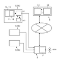
- FIG. 1 shows the overall configuration of an inspection system related to a radiation transmission test for defects in a pipe or a welded portion of a pipe member.
- the radiation transmission test of the welded portion of the pipe or the pipe member is performed based on the result of photographing with radiation. Then, based on the image data showing the distribution of the radiation transmission intensity obtained by photographing, the presence or absence of a flaw in the welded portion is confirmed, and if there is a flaw, the welding result is judged to be unacceptable and harmful. It is determined whether or not it corresponds to a "defect" that is a flaw.
- this technology is applied to non-destructive inspection of welded parts in the construction and maintenance of plants equipped with pipes that transport fluids via pipes.
- plants There are no particular restrictions on the types of plants to which this technology is applied, including natural gas plants that liquefy natural gas and separate and recover natural gas solutions, and petroleum refining plants that distill and desulfurize crude oil and various intermediate products.
- Applicable to non-destructive inspection of welds in chemical plants that produce petroleum chemicals, intermediate chemicals, polymers, etc., pharmaceutical plants that produce chemicals and their intermediate products, waste treatment plants for low-level radioactive waste, etc. can do.
- the pipes to which this technology is applied may be connected by welding and can be subjected to a radiation transmission test, and there are no particular restrictions on the material, pipe diameter, wall thickness, presence or absence of lining, etc. No. Further, the fluid flowing in the pipe may be a powder or granular material (powder, granular material, pellet, etc.) having fluidity in addition to a gas or liquid.
- the piping members to which this technology is applied are parts other than piping used when connecting equipment provided in a plant with piping.
- Examples of the piping member include flanges, elbows, tee joints, and different outer diameter piping joints.
- the welded portion to be subjected to the radiation transmission test may be any of a welded portion between the pipe and the pipe, a welded portion between the pipe and the pipe member, and a welded portion between the pipe member and the pipe member.
- the inspection system includes an imaging data acquisition unit 1 (1A to 1C) that transmits radiation such as ⁇ -rays or X-rays to the welded portion of the piping or piping member to be inspected and acquires imaging data as digital data. .. Further, based on the image data showing the distribution of the transmission intensity of radiation obtained from this imaging data, judgment data showing the result of judging the defect of the welded portion of the pipe or the pipe member to be inspected is created, and the judgment data is used as the judgment data. It includes a determination processing unit 3 that performs processing associated with image data. For example, the determination processing unit 3 is composed of a computer.
- the inspection system of this example includes an automatic determination unit 5 that provides provisional determination data that supports the determination when a qualified person makes a determination.
- the automatic determination unit 5 performs machine learning on the image data and the image information related to the flaw with the storage unit 51 that stores the image data and the determination data, and automatically determines the type of defect included in the image data based on the result of the machine learning. It is provided with a calculation unit 52 for performing the above.
- the automatic determination unit 5 can be provided as a cloud computing function, and is configured to be accessible from the determination processing unit 3 via the Internet or the like.
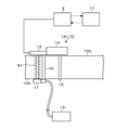
- FIG. 2 shows a configuration example of the imaging data acquisition unit 1.
- FIG. 2 shows an example of acquiring image pickup data of a portion where the ends of the two pipes 100 are connected to each other via the welded portion 81.
- the image pickup data acquisition unit 1 includes a radiation irradiation unit 11 that irradiates radiation toward the welded portion 81 of the pipe 100, and a detector 12 that detects the radiation that has passed through the welded portion 81.
- Reference numeral 13 in FIG. 2 is a device or a power source for irradiating radiation from the irradiation unit 11.
- the detector 12 detects radiation with a panel-shaped detector without using a film, and detects the radiation according to the coordinates set in the detection surface of the detector.
- a flat panel detector (FPD) capable of outputting digital data indicating the amount as imaging data can be used.
- the two pipes 100 to be inspected are abutted against the end of the pipe 100 on one side and the end of the pipe 100 on the other side, and are connected via the welded portion 81.
- the welded portion 81 is welded over the entire circumference of the pipe 100.
- FIG. 2 is described with a welded portion 81 connecting the two pipes 100 to each other, the image pickup data acquisition portion 1 of this example includes the pipe 100 and the flange, the pipe 100 and the elbow, and the flange and the elbow. It can also be used for inspection of the welded portion 81 such as.
- the radiation irradiation unit 11 and the detector 12 are arranged so as to face each other with the welded portion 81 to be inspected sandwiched by the jig 16.
- the radiation transmitted through the welded portion 81 is detected by the detector 12, and is digital data based on the transmission intensity of the radiation detected by the detector 12. The above-mentioned imaging data is acquired.
- the image pickup data acquisition unit 1 includes a moving body 14 that moves the radiation irradiation unit 11, the detector 12, and the jig 16 along a guide 15 that is a moving trajectory externally attached along the circumferential direction of the pipe 100. ..
- a moving body 14 that moves the radiation irradiation unit 11, the detector 12, and the jig 16 along a guide 15 that is a moving trajectory externally attached along the circumferential direction of the pipe 100. ..
- the moving body 14 and the guide 15 correspond to the moving mechanism of this example.
- the jig 16 of this example can freely adjust the separation distance between the radiation irradiation unit 11 and the detector 12 according to the outer diameter of the pipe 100. Further, the length of the moving track formed by the guide 15 is also freely adjustable according to the peripheral length of the pipe 100. Further, the image pickup data acquisition unit 1 controls the acquisition of the image pickup data, and also operates the control unit 2 which is an image processing unit for creating image data by combining the image pickup data described later, and the image pickup data acquisition unit 1. It is provided with an operation unit 17 that forms an operation end for the purpose and is composed of, for example, a tablet PC.
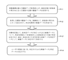
- the image pickup data acquisition unit 1 acquires image pickup data 90 at a plurality of positions along the circumferential direction of the welded portion 81 to be inspected (process P11).
- additional identification codes A and B are added to distinguish them.
- the radiation irradiation unit 11 and the detector 12 sandwich the welded portion 81 of the pipe 100 to be inspected via the jig 16. It is installed so as to face each other. Then, the welding portion 81 radiation is irradiated from the irradiation portion 11, detected by the detector 12, and the imaging data 90A is acquired based on the transmission intensity of the radiation transmitted through the welding portion 81.
- the image pickup data 90A is raw data (RAW data) corresponding to an image along the forming direction of the welded portion 81.
- the imaging data 90A the distribution of the radiation transmission intensity within the visual field range captured by one imaging in a state where the irradiation unit 11 and the detector 12 are arranged at the positions shown in FIG. 4 (a-1). Is shown.
- the image pickup data 90A shown in FIG. 4B includes a welding line 810 showing the welded portion 81 and a scratch image 8 showing the scratches.
- FIGS. 4 to 6 and 8 described below the images displayed based on the image data 9, the determined image data 91 described later, and the provisionally determined image data 92 are referred to. Reference numerals are given to indicate data 9, 91, and 92.
- the imaging data acquisition unit 1 uses a moving mechanism to move the radiation irradiation unit 11 and the detector 12 in the same direction along the circumferential direction of the pipe 100. Move in synchronization.
- the image pickup data 90B is acquired at different positions in the circumferential direction of the pipe 100 as shown in FIG. 4 (a-2).
- the imaging data 90B shown in FIG. 4 (b-2) shows the distribution of the radiation transmission intensity within the visual field range captured by imaging at the position shown in FIG. 4 (a-2).
- the arrangement position shown in FIG. 4 (b-2) was acquired at the position shown in FIG. 4 (a-2) and the image pickup data 90A acquired at the position shown in FIG. 4 (a-1). It is set so that an overlapping region D in which a part of the imaged visual field range overlaps with the imaged data 90B is formed.
- the image pickup data acquisition unit 1 of this example sequentially acquires the image pickup data 90 at a plurality of positions different in the circumferential direction of the pipe 100.
- imaging at two locations is described in FIG. 4, a plurality of imaging data 90 are acquired over the entire circumference of the welded portion 81 of the pipe 100 while further moving the irradiation unit 11 and the detector 12.
- the control unit 2 After acquiring the imaging data 90 at a plurality of positions different in the circumferential direction of the pipe 100 in this way, the control unit 2 combines the plurality of imaging data 90 to create the image data 9 shown in FIG. 4 (c). (Processing P12). At this time, for example, if the image determination of each image pickup data 90 is performed and the image pickup data 90 are combined so that the portions where the images match overlap each other, the above-mentioned overlapping region D is automatically overlapped and the circumferential direction of the pipe 100 is reached. Image data 9 combined along the line can be obtained. From the viewpoint of combining the plurality of image pickup data 90 described above, the control unit 2 provided in the image pickup data acquisition unit 1 constitutes the image processing unit of the inspection system of this example. In addition, along with the process of obtaining the image data 9 from the plurality of image pickup data 90, a process of deleting the overlapping portion may be performed as appropriate.
- image data 9 showing the distribution of the radiation transmission intensity in the circumferential direction of the pipe 100 welded portion 81 in the region surrounded by the broken line in FIG. 2 can be obtained. Further, the control unit 2 may add identification information of the image data 9 such as information of the welder who performed the welding, the place where the welding was performed, information such as the shooting date and time, and the like to the image data 9.
- the created image data 9 is sent by the determination processing unit 3 via a transportable storage medium such as a USB or SD card, or via a data communication path.
- the determination processing unit 3 includes an operation display unit 31 that displays an image based on the acquired image data 9 on a monitor and accepts input of information related to the determination result for the image data 9. Then, the qualified person 200 who determines the pass / fail of the welding result determines the presence or absence of a defect in the welded portion 81 of the pipe 100 which is the target of the radiation transmission test via the operation display unit 31 of the determination processing unit 3. ..
- the determination processing unit 3 stores the determination data indicating the result of the determination in association with the image data 9.
- FIG. 5A shows the image data 9 immediately after being combined by the image processing unit 2.
- the flaw image 8 appears in the weld line 810 indicating the welded portion 81 in the image data 9.
- the scratch image 8 can be confirmed as a portion where the transmission intensity of the radiation transmitted through the welded portion 81 is different (a portion where the contrast of the image is different).
- the qualified person 200 operates the operation display unit 31 while visually observing the displayed image, and marks it so as to surround the flaw image 8 which is determined to be defective as shown in FIG. 5 (b). Perform the process of adding 80 (markup). In this way, the qualified person 200 writes the mark 80 indicating the position of the scratch image 8 corresponding to the defect and the size of the scratch image 8 on the image data 9.
- all the marks-up flaws are determined to be "defects”.
- all the flaws (scratch image 8) that can be discriminated from the image may be marked up, and the identification information may be further added to those determined to be defects.
- the scratch image 8 to which the identification information indicating the defect is added may be displayed as an image having a color or hatch different from that of other flaws that are not defects.
- the information indicating the position of the flaw image 8 and the size of the flaw image 8 identified by marking up the flaw image 8 determined to be a defect corresponds to the determination data indicating the result of determining the defect. do.
- the image data 9 and the defect determination data are associated with each other and stored in a storage unit (not shown) of the determination processing unit 3 (processing P13).
- the image data 9 to which the determination data is associated is also referred to as the determined image data 91.
- the determination processing unit 3 receives a request for displaying the determination result of the welding unit 81 for which the determination result is to be confirmed from a user such as the person in charge of construction of the plant, the determination processing unit 3 calls the determined image data 91 from a storage unit (not shown) to obtain an image. Is output as (process P14).
- the position information of each weld line 810 of each weld 81 is the item number of the pipe 100 or the pipe member added to the determined image data 91, the location of the weld, the shooting date and time, and the distance from the radiation transmission test start point ( Normally, the starting point is set to 0, and the position information can be identified as 1, 2, 3 in increments of 10 mm).
- the output unit for outputting the determination result by the user may be provided in a place different from the determination processing unit 3 and may be configured to acquire the determined image data 91 via the cloud or the like.
- the inspection system there are the following effects.
- radiation is transmitted through the welded portion 81 of the pipe 100 or the pipe member to be inspected, and the image pickup data 90 of the welded portion 81 is acquired.
- the image pickup data 90 is used to determine a defect in the welded portion 81 to be inspected, and the determination data indicating the determination result is associated with the image data 9 indicating the distribution of the transmission intensity of the radiation.
- the determination result can be obtained without using a film, and the work efficiency of the radiation transmission test can be improved by reducing the burden on the operator. Further, by using the image data, it is possible to enlarge the image, adjust the contrast, invert the negative / positive, and the like, so that the inspection accuracy and the inspection efficiency can be improved as compared with the visual determination using the film.
- the control unit 2 can be remotely controlled while ensuring a safe distance.
- the radiation irradiation unit 11 and the detector 12 are moved to move the irradiation unit 11 and the detector 12 to the entire circumference of the welded portion 81 without installing the film on the welded portion 81 and entering and exiting the worker from the radiation area each time. It is possible to shoot continuously over the entire period. Further, regardless of the skill of the operator who performs the imaging, it is possible to acquire the imaging data 90 with little variation in the imaging accuracy and improve the inspection accuracy. Further, since the image pickup data 90, which is digital data, is directly acquired, it is easy to confirm the image at the site, and the risk of re-shooting when the shooting fails can be reduced.
- the image data 9 which is digital data can be transmitted to a remote place, and the restrictions on the dispatch of the qualified person 200 can be significantly reduced.
- ASME American Society of Mechanical Engineers
- “Crack” shown in Table 1 is a defect in which the welded portion 81 is cracked
- “Lack of Fusion” is a defect in which the welding material is not completely melted and a void is generated inside the welded portion 81. Is.
- "Incomplete Penetration” is a defect in which the welding material cannot completely fill the space between the pipe 100 and the pipe 100, and a dent is formed in the welded portion 81 on the inner surface side of the pipe 100.
- the scratches remaining on the surface of the welded portion 81 are classified into a "rounded shape (Rounded Indication)" and a “linear shape (Elongated Indication)”.
- Other defects include “Undercutting” in which a gap is created between the welding material and the pipe 100 on the surface side, and "Concave Surface” in which the surface of the welded portion 81 is dented. ..
- the flaw image 8A included in the weld line 810 in FIG. 6 (a) shows a flaw corresponding to a defect “crack”, and the flaw image 8B in FIG. 6 (b) shows a flaw of “fusion failure”. There is. Further, the flaw image 8C in FIG. 6C shows a flaw of “poor penetration”.
- the qualified person 200 determines the position and size of the flaw formed in the welded portion 81 based on the position of the flaw image 8 in the image, the size of the flaw image 8, and the shape characteristics of the flaw image 8 in this way. However, if the flaw corresponds to a defect, judgment data indicating that fact is added. Identification information that identifies the type of defect may be added to this determination data.
- the inspection system As shown in FIG. 1, the position of the scratch image 8 included in the image data 9, the size of the scratch image 8, and the shape characteristics of the scratch image 8 are shown in Table 1.
- the automatic determination unit 5 may be provided, which determines which type of defect corresponds to, adds information for identifying the type of defect, and performs markup.
- the automatic determination unit 5 acquires the determined image data 91, which is the image data 9 associated with the determination data, from the determination processing unit 3, and stores a large amount in the storage unit 51. Then, the automatic determination unit 5 reads out the determined image data 91 stored in the storage unit 51, and performs machine learning about the position, size, and shape feature of the flaw image 8 determined to be defective (process P21). .. Further, at this time, machine learning may be performed on the position, size, and shape feature of the flaw image 8 that has not been determined to be a defect.
- the automatic determination unit 5 determines whether or not the flaw contained in the new image data 9 corresponds to a defect based on the result of machine learning of the flaw, and AI is a calculation procedure for determining the type of the defect. (Artificial Intelligent) Build a judgment algorithm.
- the AI determination algorithm for example, the welded portion 81 is included in the image data 9 and is based on the area of the portion having a contrast different from that of the surrounding weld line 810, the shape, the forming direction, the tendency of the gradation change of the contrast, and the like. In addition to recognizing the flaws contained in, it is possible to determine whether or not the flaw corresponds to a defect and to determine the type of defect.
- the automatic determination unit 5 receives the image data 9 before the determination process from the determination processing unit 3, and automatically determines the acquired image data 9 based on the AI determination algorithm.
- the position of the flaw image 8, the size of the flaw image 8, and the shape characteristics of the flaw image 8 are extracted, and it is determined whether or not the flaw corresponding to the flaw image 8 corresponds to a defect. If it is determined that the flaw corresponds to a defect, the type of defect is further determined.
- the type of defect is used as provisional determination data that is information that can identify the position of the flaw image 8, the size of the flaw image 8, and the shape feature of the flaw image 8. Mark-up for associating the mark 80 including the information indicating the above is performed (process P22).
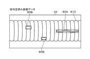
- the image data 9 to which the provisional determination data is associated is also referred to as the provisional determination completed image data 92.
- the mark 80A is attached to the portion corresponding to the defect determined to be "cracking", and the mark 80B is attached to the portion corresponding to the defect determined to be "fusion failure”. ..
- These marks 80A and 80B are associated with various defects exemplified in Table 1 in advance, and are set to have different colors or hatch types so that they can be visually distinguished from each other.
- the image data 9 (provisionally determined image data 92) to which the provisional determination data including the information indicating the type of the defect is added is transmitted to the determination processing unit 3 and stored in the storage unit 31.
- the determination processing unit 3 determines the tentatively determined image data 92 as shown in the process P13'of FIG.
- the image of the above is displayed, and the determination of the defect by the qualified person 200 is accepted.
- the provisional determination data is adopted as it is, or the provisional determination data is modified and saved as formal determination data in association with the image data 9.
- the calculation unit 52 may be provided in the determination processing unit 3. That is, the AI determination algorithm may be provided in the determination processing unit 3. Thereby, the time for transmitting and receiving the image data 9 can be reduced. In addition, the AI determination algorithm can be used even in places where the Internet is not available.
- the image pickup data acquisition unit 1 provided in the inspection system may be configured by an image reading device that scans the captured analog image to acquire the image pickup data 90.
- an analog image 93 obtained by irradiating a region including a welded portion 81 to be inspected with radiation and exposing a film to a radiation image transmitted through the welded portion 81 is obtained.
- the analog image 93 can acquire the image pickup data 90 converted into digital data by reading the analog image 93 through the image reading device 19.
- FIG. 10 shows an example of acquiring image pickup data 90 from analog images 93 taken at a plurality of locations by using one image reading device 19.
- the present invention is not limited to the illustrated example, and each of these analog images 93 may be read by a plurality of different image reading devices 19 to acquire image pickup data 90.
- the image processing of the image pickup data 90 read through the image reading device 19 can be performed, and the determination processing unit 3 can associate the determination data with the obtained image data 9.
- the user can easily acquire the determined image data 91 to which the determination data is associated, which is the same as the inspection system according to the first embodiment described with reference to FIG.
- Image data acquisition unit 3 Judgment processing unit 9 Image data 90 Image data 81 Welding unit 91 Judgment image data 100 Piping
Landscapes
- Chemical & Material Sciences (AREA)
- Health & Medical Sciences (AREA)
- Life Sciences & Earth Sciences (AREA)
- Engineering & Computer Science (AREA)
- General Physics & Mathematics (AREA)
- Physics & Mathematics (AREA)
- Immunology (AREA)
- Analytical Chemistry (AREA)
- Biochemistry (AREA)
- General Health & Medical Sciences (AREA)
- Pathology (AREA)
- Food Science & Technology (AREA)
- Medicinal Chemistry (AREA)
- Computer Vision & Pattern Recognition (AREA)
- Quality & Reliability (AREA)
- Theoretical Computer Science (AREA)
- Crystallography & Structural Chemistry (AREA)
- Toxicology (AREA)
- Analysing Materials By The Use Of Radiation (AREA)
Abstract
Description
これらのプラントは、例えば塔槽や熱交換器などの静機器、ポンプなどの動機器などの多数の機器群を配置した構造となっている。そしてこれら機器群を構成する機器同士の間には、流体の授受を行う配管が接続されている。
このような種々の課題を解決するため、作業能率向上および作業者の負担をより軽減することが可能な溶接部の検査技術の確立が求められている。
このように、従来、フィルムを用いずに放射線の透過量を検出する手法は、稼働しているプラントの配管の減肉管理に用いられているに過ぎなかった。
検査対象の配管または配管部材の溶接部に放射線を透過させて得た撮像データを取得する撮像データ取得部と、
前記撮像データから得られた前記放射線の透過強度の分布に基づいて前記検査対象の溶接部の欠陥を判定した結果を示す判定データを、当該放射線の透過強度の分布を示す画像データに対応付ける処理を行う判定処理部と、
を備えたことを特徴とする。
(a)前記撮像データ取得部は、前記検査対象の溶接部を挟んで互いに対向して配置され、当該溶接部へ向けて放射線を照射する放射線照射部と、前記溶接部を透過した放射線を検出する検出器と、を備え、前記検出器にて検出された放射線の透過強度に基づきディジタルデータにて、前記撮像データを取得すること。
(b)前記撮像データ取得部は、
前記検査対象の溶接部を挟んで前記放射線照射部及び前記検出器を対向させて配置するための治具と、
前記治具により対向して配置された状態を保ちながら、前記放射線照射部及び前記検出部を同期させながら前記溶接部の周方向に移動させることにより、前記放射線を照射する位置を前記周方向に移動させる移動機構と、を備え、
前記溶接部の周方向の異なる複数の位置にて前記撮像データを夫々取得すること。
(c)前記溶接部の周方向に異なる複数の位置において取得された複数の撮像データを、前記周方向に沿って結合させて、前記画像データを作成する画像処理部を備えたこと。
(d)前記検査対象の溶接部を含む領域に放射線を照射し、当該溶接部を透過した放射線像をフィルムに感光させて得られたアナログ画像をディジタル画像に変換し、前記ディジタル画像を前記撮像データとすること。
(e)前記判定データは前記画像データに含まれる溶接線におけるきずの位置およびきずのサイズ、きずの形状的特徴を識別可能な情報と対応付けられ、前記溶接部の溶接の結果が不合格と判定される有害なきずである欠陥の種類を示す情報を含むことと、
前記判定データが対応付けられた過去の画像データに含まれるきずの機械学習を実施した結果に基づいて、新たな放射線の透過強度の分布の画像データについて、溶接線におけるきずの位置およびきずのサイズ、きずの形状的特徴を特定して想定される欠陥の種類を自動判定した仮判定データを対応付ける自動判定部を備えることと、
前記判定処理部は、前記自動判定処理部にて前記画像データに対応付けられた仮判定データを基に判定することにより、前記判定データを画像データに対応付ける処理を行うこと。
(f)前記判定処理部は、前記自動判定部にて前記画像データに対応付けられた仮判定データを修正する処理を受け付けることが可能なように構成されたこと。
検査対象の配管または配管部材の溶接部に放射線を透過させて得た前記放射線の透過強度の分布に基づいて前記検査対象の配管の溶接部の欠陥を判定した結果を示す判定データを、当該放射線の透過強度の分布を示す画像データに対応付ける処理を行うように構成されたことを特徴とする。
検査対象の配管または配管部材の溶接部に放射線を透過させて得た前記放射線の透過強度の分布に基づいて前記検査対象の溶接部の欠陥を判定した結果を示す判定データを、当該放射線の透過強度の分布を示す画像データに対応付ける処理を行う工程を含むことを特徴とする。
放射線透過試験の対象となる溶接部は、配管と配管との溶接部、配管と配管部材との溶接部、配管部材と配管部材との溶接部のいずれであってもよい。
この点につき、本例の検査システムは、有資格者が判定を行うにあたって、判定をサポートする仮判定データを提供する自動判定部5を備えている。自動判定部5は、画像データ及び判定データを記憶する記憶部51と、きずに係る画像情報についての機械学習を行うと共に、機械学習の結果に基づいて画像データに含まれる欠陥の種類の自動判定を行う演算部52とを備えている。例えば図1に示すように、自動判定部5は、クラウドコンピューティング機能として提供することが可能であり、判定処理部3からインターネットなどを介してアクセスできるように構成されている。
また撮像データ取得部1は、撮像データの取得を制御すると共に、後述する撮像データの結合を実施して画像データを作成する画像処理部である制御部2や、撮像データ取得部1を操作するための操作端を成し例えばタブレットPCなどにより構成される操作部17を備えている。
なお説明の便宜上、以下に説明する図4~図6、図8では、画像データ9や後述の判定済み画像データ91、仮判定済み画像データ92に基づいて表示される画像に対して、これらのデータ9、91、92を示す符号を付してある。
このとき図4(b-2)に示す配置位置は、図4(a-1)に示す位置にて取得された撮像データ90Aと、図4(a-2)に示す位置にて取得された撮像データ90Bとの間で、撮像された視野範囲の一部が重複する重複領域Dが形成されるように設定されている。
以上に説明した複数の撮像データ90の結合を行う観点において、撮像データ取得部1に設けられている制御部2は、本例の検査システムの画像処理部を構成している。なお、複数の撮像データ90から画像データ9を得る処理に伴って、適宜、重なっている部分を削除する処理を行ってもよい。
撮像データ取得部1を用いて撮像を行った溶接部81にきずが含まれている場合には、画像データ9には、溶接部81を示す溶接線810内に、きず画像8が現れる。例えばきず画像8は、溶接部81を透過した放射線の透過強度が異なる部位(画像のコントラストが異なる部位)として確認できる。
また、画像から判別可能なすべてのきず(きず画像8)をマークアップし、そのうち欠陥と判定されるものに識別情報をさらに付加する構成としてもよい。このとき、欠陥であることを示す識別情報が付加されたきず画像8は、欠陥ではない他のきずとは異なる色やハッチングを付した画像として表示してもよい。
判定処理部3は、プラントの建設責任者などのユーザーから、判定結果を確認したい溶接部81の判定結果の表示要求を受け付けると、不図示の記憶部より、判定済み画像データ91を呼び出して画像として出力する(処理P14)。各溶接部81の各溶接線810の位置情報は、判定済み画像データ91に付加されている配管100や配管部材のアイテム番号や溶接部の場所、撮影日時、放射線透過試験開始点からの距離(通常、開始点を0とし、10mm刻みに1,2,3と位置情報を識別)などの識別情報に基づいて識別することができる。なお、ユーザーが判定結果を出力する出力部は、判定処理部3とは異なる場所に設け、クラウドなどを介して判定済み画像データ91を取得する構成としてもよい。
この点、ディジタルデータである撮像データ90A、90Bを取得することで、フィルムを保管する倉庫の確保や、フィルムの現像に要する薬品の取り扱いの必要が必要なくなる。
この点、図2を用いて説明したように、放射線照射部11及び検出器12を移動させること可能な構成の撮像データ取得部1を用いれば、安全距離を確保したうえで制御部2により遠隔操作を実施することが可能となり、フィルムよりも高感度の高い検出器を用いることで、より小さい線源を用いても作業能率を損なうことなく、より多くの放射線透過試験を並行して実施することもできる。また溶接部81へのフィルムの設置, 都度、放射線エリアからの作業者の入退場を行うことなく、放射線照射部11及び検出器12を移動させて、撮像データ90を溶接部81の全周に亘って連続的に撮影することができる。さらに撮影を実施する作業者の技能によらず、撮像精度のばらつきの少ない撮像データ90を取得して、検査精度を向上させることができる。またディジタルデータである撮像データ90を直接、取得するため、現場での画像の確認が容易であり、撮影を失敗した場合の再撮影のリスクを減らすことができる。
この点、ディジタルデータである画像データ9は遠隔地にも送信することが可能であり、有資格者200の派遣に係る制約を大幅に低減することができる。この観点で、図1に示す判定処理部3を、クラウドを介して画像データ9や判定済み画像データの送受信を行う独立した判定処理装置として構成し、画像データ9に判定データを付加するサービスのみを提供してもよい。
[表1]

そこで本発明の実施の形態に係る検査システムは、図1に示すように、画像データ9中に含まれるきず画像8の位置、きず画像8のサイズ、きず画像8の形状的特徴が、表1に示したいずれの種類の欠陥に相当するかを判別し、欠陥の種類を識別する情報を付加してマークアップを実施する自動判定部5を備えていてもよい。
そして自動判定部5は、記憶部51に蓄積されている判定済み画像データ91を読み出し、欠陥と判断されたきず画像8の位置、サイズ及び形状的特徴についての機械学習を実施する(処理P21)。また、このとき、欠陥と判断されるには至らなかったきず画像8の位置、サイズ及び形状的特徴についての機械学習も行ってよい。
また演算部52が判定処理部3に設けられていてもよい。つまり、AI判定アルゴリズムが判定処理部3に設けられていてもよい。それにより画像データ9の送受信の時間を削減することができる。また、インターネットが利用できない場所でもAI判定アルゴリズムを利用することができる。
3 判定処理部
9 画像データ
90 撮像データ
81 溶接部
91 判定済み画像データ
100 配管
Claims (13)
- 配管または配管部材の溶接部の欠陥の非破壊検査に係る検査システムであって、
検査対象の配管または配管部材の溶接部に放射線を透過させて得た撮像データを取得する撮像データ取得部と、
前記撮像データから得られた前記放射線の透過強度の分布に基づいて前記検査対象の溶接部の欠陥を判定した結果を示す判定データを、当該放射線の透過強度の分布を示す画像データに対応付ける処理を行う判定処理部と、
を備えたことを特徴とする検査システム。 - 前記撮像データ取得部は、前記検査対象の溶接部を挟んで互いに対向して配置され、当該溶接部へ向けて放射線を照射する放射線照射部と、前記溶接部を透過した放射線を検出する検出器と、を備え、前記検出器にて検出された放射線の透過強度に基づきディジタルデータにて、前記撮像データを取得することを特徴とする請求項1に記載の検査システム。
- 前記撮像データ取得部は、
前記検査対象の溶接部を挟んで前記放射線照射部及び前記検出器を対向させて配置するための治具と、
前記治具により対向して配置された状態を保ちながら、前記放射線照射部及び前記検出部を同期させながら前記溶接部の周方向に移動させることにより、前記放射線を照射する位置を前記周方向に移動させる移動機構と、を備え、
前記溶接部の周方向の異なる複数の位置にて前記撮像データを夫々取得することを特徴とする請求項2に記載の検査システム。 - 前記溶接部の周方向に異なる複数の位置において取得された複数の撮像データを、前記周方向に沿って結合させて、前記画像データを作成する画像処理部を備えたことを特徴とする請求項3に記載の検査システム。
- 前記検査対象の溶接部を含む領域に放射線を照射し、当該溶接部を透過した放射線像をフィルムに感光させて得られたアナログ画像をディジタル画像に変換し、前記ディジタル画像を前記撮像データとすることを特徴とする請求項1に記載の検査システム。
- 前記判定データは前記画像データに含まれる溶接線におけるきずの位置およびきずのサイズ、きずの形状的特徴を識別可能な情報と対応付けられ、前記溶接部の溶接の結果が不合格と判定される有害なきずである欠陥の種類を示す情報を含むことと、
前記判定データが対応付けられた過去の画像データに含まれるきずの機械学習を実施した結果に基づいて、新たな放射線の透過強度の分布の画像データについて、溶接線におけるきずの位置およびきずのサイズ、きずの形状的特徴を特定して想定される欠陥の種類を自動判定した仮判定データを対応付ける自動判定部を備えることと、
前記判定処理部は、前記自動判定処理部にて前記画像データに対応付けられた仮判定データを基に判定することにより、前記判定データを画像データに対応付ける処理を行うことと、を特徴とする請求項1に記載の検査システム。 - 前記判定処理部は、前記自動判定部にて前記画像データに対応付けられた仮判定データを修正する処理を受け付けることが可能なように構成されたことを特徴とする請求項6記載の検査システム。
- 配管または配管部材の溶接部の欠陥の非破壊検査に係る判定処理を行う判定処理装置であって、
検査対象の配管または配管部材の溶接部に放射線を透過させて得た前記放射線の透過強度の分布に基づいて前記検査対象の配管の溶接部の欠陥を判定した結果を示す判定データを、当該放射線の透過強度の分布を示す画像データに対応付ける処理を行うように構成されたことを特徴とする判定処理装置。 - 前記判定データは前記画像データに含まれる溶接線における前記溶接部のきずの位置およびきずのサイズ、きずの形状的特徴を識別可能な情報と対応付けられ、前記溶接部の溶接の結果が不合格と判定される有害なきずである欠陥の種類を示す情報を含むことと、
前記判定データが対応付けられた過去の画像データに含まれるきずの機械学習を実施した結果に基づいて、新たな放射線の透過強度の分布について、溶接線におけるきずの位置およびきずのサイズ、きずの形状的特徴を特定して想定される欠陥の種類を仮判定データとして対応付ける自動判定が行われた画像データを取得し、前記仮判定データを基に判定することにより、前記判定データを画像データに対応付ける処理を行うことを特徴とする請求項8に記載の判定処理装置。 - 前記画像データに対応付けられた前記仮判定データを修正する処理を受け付けることが可能なように構成されたことを特徴とする請求項9記載の判定処理装置。
- 配管または配管部材の溶接部の欠陥の非破壊検査に係る検査方法であって、
検査対象の配管または配管部材の溶接部に放射線を透過させて得た前記放射線の透過強度の分布に基づいて前記検査対象の溶接部の欠陥を判定した結果を示す判定データを、当該放射線の透過強度の分布を示す画像データに対応付ける処理を行う工程を含むことを特徴とする検査方法。 - 前記判定データは前記画像データに含まれる溶接線におけるきずの位置およびきずのサイズ、きずの形状的特徴を識別可能な情報と対応付けられ、前記溶接部の溶接の結果が不合格と判定される有害なきずである欠陥の種類を示す情報を含むことと、
前記画像データに判定データを対応付ける処理を行う工程は、前記判定データが対応付けられた過去の画像データに含まれるきずの機械学習を実施した結果に基づいて、新たな放射線の透過強度の分布について、溶接線におけるきずの位置およびきずのサイズ、きずの形状的特徴を特定して想定される欠陥の種類を仮判定データとして対応付ける自動判定が行われた画像データを取得し、前記仮判定データを基に判定することにより、前記判定データを画像データに対応付ける処理を含むことを特徴とする請求項11に記載の検査方法。 - 前記画像データに判定データを対応付ける処理を行う工程は、前記画像データに対応付けられた前記仮判定データを修正する処理を含むことを特徴とする請求項12記載の検査方法。
Priority Applications (6)
| Application Number | Priority Date | Filing Date | Title |
|---|---|---|---|
| DE112020007436.6T DE112020007436T5 (de) | 2020-07-16 | 2020-07-16 | Prüfsystem, bestimmungsverarbeitungsvorrichtung und prüfverfahren |
| US17/638,176 US12105033B2 (en) | 2020-07-16 | 2020-07-16 | Inspection system, determination processing apparatus, and inspection method |
| CN202080058738.7A CN114270181B (zh) | 2020-07-16 | 2020-07-16 | 检查系统、判定处理系统、判定处理装置以及检查方法 |
| KR1020227008353A KR102899113B1 (ko) | 2020-07-16 | 2020-07-16 | 검사 시스템, 판정 처리 장치 및 검사 방법 |
| PCT/JP2020/027719 WO2022014019A1 (ja) | 2020-07-16 | 2020-07-16 | 検査システム、判定処理装置、及び検査方法 |
| JP2021563725A JP7221419B2 (ja) | 2020-07-16 | 2020-07-16 | 検査システム、判定処理装置、及び検査方法 |
Applications Claiming Priority (1)
| Application Number | Priority Date | Filing Date | Title |
|---|---|---|---|
| PCT/JP2020/027719 WO2022014019A1 (ja) | 2020-07-16 | 2020-07-16 | 検査システム、判定処理装置、及び検査方法 |
Publications (1)
| Publication Number | Publication Date |
|---|---|
| WO2022014019A1 true WO2022014019A1 (ja) | 2022-01-20 |
Family
ID=79554594
Family Applications (1)
| Application Number | Title | Priority Date | Filing Date |
|---|---|---|---|
| PCT/JP2020/027719 Ceased WO2022014019A1 (ja) | 2020-07-16 | 2020-07-16 | 検査システム、判定処理装置、及び検査方法 |
Country Status (6)
| Country | Link |
|---|---|
| US (1) | US12105033B2 (ja) |
| JP (1) | JP7221419B2 (ja) |
| KR (1) | KR102899113B1 (ja) |
| CN (1) | CN114270181B (ja) |
| DE (1) | DE112020007436T5 (ja) |
| WO (1) | WO2022014019A1 (ja) |
Cited By (1)
| Publication number | Priority date | Publication date | Assignee | Title |
|---|---|---|---|---|
| WO2025023191A1 (ja) | 2023-07-21 | 2025-01-30 | 富士フイルム株式会社 | 制御装置、制御方法、及び制御プログラム |
Families Citing this family (3)
| Publication number | Priority date | Publication date | Assignee | Title |
|---|---|---|---|---|
| WO2023137474A1 (en) * | 2022-01-13 | 2023-07-20 | Varex Imaging Corporation | Inspection system |
| KR102781027B1 (ko) * | 2022-11-02 | 2025-03-18 | 한화오션 주식회사 | 인공신경망을 활용한 배관조인트 용접부 비파괴검사 시스템 및 방법 |
| KR102832617B1 (ko) * | 2024-01-05 | 2025-07-09 | 두산에너빌리티 주식회사 | 영상 분석 기반의 배관의 두께 측정을 위한 장치 및 이를 위한 방법 |
Citations (5)
| Publication number | Priority date | Publication date | Assignee | Title |
|---|---|---|---|---|
| JPH0260861A (ja) * | 1988-07-28 | 1990-03-01 | Parapluie Ltd | 総合車両修理センター、その組立方法及び車両修理方法 |
| JP2000180387A (ja) * | 1998-12-14 | 2000-06-30 | Japan Steel & Tube Constr Co Ltd | X線検査装置及びx線検査方法 |
| US20120201347A1 (en) * | 2009-08-28 | 2012-08-09 | Shawcor Ltd. | Method and apparatus for external pipeline weld inspection |
| JP2013195119A (ja) * | 2012-03-16 | 2013-09-30 | Hitachi-Ge Nuclear Energy Ltd | 放射線透過デジタル画像を用いた検査方法及びその装置 |
| WO2019059011A1 (ja) * | 2017-09-19 | 2019-03-28 | 富士フイルム株式会社 | 教師データ作成方法及び装置並びに欠陥検査方法及び装置 |
Family Cites Families (17)
| Publication number | Priority date | Publication date | Assignee | Title |
|---|---|---|---|---|
| JPH07119714B2 (ja) * | 1990-01-12 | 1995-12-20 | 川崎重工業株式会社 | 溶接欠陥の種類推定方法 |
| JP2968442B2 (ja) | 1994-09-26 | 1999-10-25 | 川崎重工業株式会社 | 溶接欠陥の評価システム |
| JPH10148622A (ja) * | 1996-11-18 | 1998-06-02 | Kawasaki Steel Corp | 溶接部放射線透過試験画像の自動合否判定方法及び装置 |
| JP5022820B2 (ja) | 2007-08-13 | 2012-09-12 | 日立Geニュークリア・エナジー株式会社 | 放射線検査装置及びそれを用いた配管検査方法 |
| JP2009236593A (ja) | 2008-03-26 | 2009-10-15 | Mitsubishi Electric Corp | 外観検査支援装置 |
| US8274013B2 (en) * | 2009-03-09 | 2012-09-25 | Lincoln Global, Inc. | System for tracking and analyzing welding activity |
| JP2011127921A (ja) * | 2009-12-15 | 2011-06-30 | Jfe Engineering Corp | X線透過画像の欠陥判定方法及び装置 |
| JP6930926B2 (ja) * | 2016-01-29 | 2021-09-01 | 富士フイルム株式会社 | 欠陥検査装置、方法およびプログラム |
| JP6631413B2 (ja) * | 2016-06-02 | 2020-01-15 | 日本製鉄株式会社 | 周溶接部の検査方法 |
| KR20180000504A (ko) * | 2016-06-23 | 2018-01-03 | 대우조선해양 주식회사 | 비파괴 검사 자동화 장치 및 자동화 방법 |
| JP6825846B2 (ja) | 2016-08-10 | 2021-02-03 | 旭化成株式会社 | 保全支援装置、保全支援用プログラム、及び保全支援方法 |
| KR20180039843A (ko) * | 2016-10-11 | 2018-04-19 | 대우조선해양 주식회사 | 방사선 투과검사를 통한 비파괴 검사장치 |
| WO2018088259A1 (ja) * | 2016-11-14 | 2018-05-17 | 三菱重工業株式会社 | 配管検査装置 |
| JP6825469B2 (ja) * | 2017-04-18 | 2021-02-03 | 日本製鉄株式会社 | 周溶接部の検査方法 |
| JP6923794B2 (ja) | 2017-08-04 | 2021-08-25 | 富士通株式会社 | 検査装置、検査プログラム、及び検査方法 |
| JP7050470B2 (ja) | 2017-11-21 | 2022-04-08 | 千代田化工建設株式会社 | 検査支援システム、学習装置、及び判定装置 |
| JP2020144688A (ja) | 2019-03-07 | 2020-09-10 | 株式会社Ihi | 学習方法、学習装置、及び当該学習装置を備える溶接欠陥検出装置 |
-
2020
- 2020-07-16 KR KR1020227008353A patent/KR102899113B1/ko active Active
- 2020-07-16 JP JP2021563725A patent/JP7221419B2/ja active Active
- 2020-07-16 CN CN202080058738.7A patent/CN114270181B/zh active Active
- 2020-07-16 DE DE112020007436.6T patent/DE112020007436T5/de active Pending
- 2020-07-16 WO PCT/JP2020/027719 patent/WO2022014019A1/ja not_active Ceased
- 2020-07-16 US US17/638,176 patent/US12105033B2/en active Active
Patent Citations (5)
| Publication number | Priority date | Publication date | Assignee | Title |
|---|---|---|---|---|
| JPH0260861A (ja) * | 1988-07-28 | 1990-03-01 | Parapluie Ltd | 総合車両修理センター、その組立方法及び車両修理方法 |
| JP2000180387A (ja) * | 1998-12-14 | 2000-06-30 | Japan Steel & Tube Constr Co Ltd | X線検査装置及びx線検査方法 |
| US20120201347A1 (en) * | 2009-08-28 | 2012-08-09 | Shawcor Ltd. | Method and apparatus for external pipeline weld inspection |
| JP2013195119A (ja) * | 2012-03-16 | 2013-09-30 | Hitachi-Ge Nuclear Energy Ltd | 放射線透過デジタル画像を用いた検査方法及びその装置 |
| WO2019059011A1 (ja) * | 2017-09-19 | 2019-03-28 | 富士フイルム株式会社 | 教師データ作成方法及び装置並びに欠陥検査方法及び装置 |
Cited By (1)
| Publication number | Priority date | Publication date | Assignee | Title |
|---|---|---|---|---|
| WO2025023191A1 (ja) | 2023-07-21 | 2025-01-30 | 富士フイルム株式会社 | 制御装置、制御方法、及び制御プログラム |
Also Published As
| Publication number | Publication date |
|---|---|
| CN114270181B (zh) | 2025-10-31 |
| US20220299451A1 (en) | 2022-09-22 |
| CN114270181A (zh) | 2022-04-01 |
| KR20230035511A (ko) | 2023-03-14 |
| JPWO2022014019A1 (ja) | 2022-01-20 |
| US12105033B2 (en) | 2024-10-01 |
| DE112020007436T5 (de) | 2023-04-27 |
| JP7221419B2 (ja) | 2023-02-13 |
| KR102899113B1 (ko) | 2025-12-15 |
Similar Documents
| Publication | Publication Date | Title |
|---|---|---|
| JP7221419B2 (ja) | 検査システム、判定処理装置、及び検査方法 | |
| WO2019102892A1 (ja) | 検査支援システム、学習装置、及び判定装置 | |
| KR20180000504A (ko) | 비파괴 검사 자동화 장치 및 자동화 방법 | |
| JP3853751B2 (ja) | 非破壊検査システム | |
| Kersting et al. | High end inspection by filmless radiography on LSAW large diameter pipes | |
| KR20220071462A (ko) | 클라우드 기반의 배관 비파괴 검사시스템 | |
| RU2736074C1 (ru) | Способ промышленного радиографического контроля с помощью детектора и связанного с детектором по беспроводной или проводной связи устройства управления | |
| JP7476082B2 (ja) | 非破壊検査の支援装置、支援方法及び支援プログラム | |
| Liessem et al. | State-of-the-art quality control during production of SAW linepipes | |
| RO131491A2 (ro) | Metodă şi sistem de examinare a ţevilor şi fitingurilor sudate din materiale termoplastice | |
| US20040146140A1 (en) | Pipeline wall inspection apparatus | |
| KR102913893B1 (ko) | 열화상 데이터 기반 강관 용접부 결함 검출 방법 | |
| JP7181356B1 (ja) | 配管溶接部の検査装置 | |
| Silva et al. | Using External Automated Ultrasonic Inspection (C-Scan) for Mapping Internal Corrosion on Offshore Caissons | |
| Ostromęcka | Ionising Radiation in Non-Destructive Testing. Part 2–Selected Issues Related to the Implementation of Radiographic Testing for the Diagnosis of Rail Joints on PKP PLK SA Infrastructure | |
| Allard et al. | Pipeline external corrosion analysis using a 3D laser scanner | |
| JPH0623647B2 (ja) | 放射線透過試験の欠陥判別方法 | |
| Sood et al. | NDE Welds Inspection Qualifications for Pipework and Pipelines | |
| Acquah | Assessing the conventional Non-Destructive Testing methods used for the inspection and testing of welded joints in fuel pipelines | |
| Mohd Ramli et al. | Composite Repairs Integrity Assessment: An Overview of Inspection Techniques | |
| Wardhani | RADIOGRAPHIC EXAMINATION PROCEDURE AS NON DESTRUCTIVE TESTING METHOD IN PROCESS PIPING | |
| Sattler | Success in Managing Nondestructive Testing (Part 7) | |
| NCHRP | TESTING OF IN-SERVICE BRIDGES USING AUTOMATED ULTRASONIC TESTING METHODS | |
| Fraser et al. | Pipeline Corrosion and Mechanical Damage Analysis Using a 3D Laser Scanner | |
| Mori et al. | Digital image acquisition method for film based radiographic testing |
Legal Events
| Date | Code | Title | Description |
|---|---|---|---|
| ENP | Entry into the national phase |
Ref document number: 2021563725 Country of ref document: JP Kind code of ref document: A |
|
| 121 | Ep: the epo has been informed by wipo that ep was designated in this application |
Ref document number: 20944838 Country of ref document: EP Kind code of ref document: A1 |
|
| 122 | Ep: pct application non-entry in european phase |
Ref document number: 20944838 Country of ref document: EP Kind code of ref document: A1 |
|
| WWG | Wipo information: grant in national office |
Ref document number: 202080058738.7 Country of ref document: CN |