WO2022009696A1 - 演算システム、電池の検査方法、及び電池の検査プログラム - Google Patents
演算システム、電池の検査方法、及び電池の検査プログラム Download PDFInfo
- Publication number
- WO2022009696A1 WO2022009696A1 PCT/JP2021/024121 JP2021024121W WO2022009696A1 WO 2022009696 A1 WO2022009696 A1 WO 2022009696A1 JP 2021024121 W JP2021024121 W JP 2021024121W WO 2022009696 A1 WO2022009696 A1 WO 2022009696A1
- Authority
- WO
- WIPO (PCT)
- Prior art keywords
- soc
- battery
- product
- ocv
- specifications
- Prior art date
- Legal status (The legal status is an assumption and is not a legal conclusion. Google has not performed a legal analysis and makes no representation as to the accuracy of the status listed.)
- Ceased
Links
Images



Classifications
-
- G—PHYSICS
- G01—MEASURING; TESTING
- G01R—MEASURING ELECTRIC VARIABLES; MEASURING MAGNETIC VARIABLES
- G01R31/00—Arrangements for testing electric properties; Arrangements for locating electric faults; Arrangements for electrical testing characterised by what is being tested not provided for elsewhere
- G01R31/36—Arrangements for testing, measuring or monitoring the electrical condition of accumulators or electric batteries, e.g. capacity or state of charge [SoC]
- G01R31/367—Software therefor, e.g. for battery testing using modelling or look-up tables
-
- G—PHYSICS
- G01—MEASURING; TESTING
- G01R—MEASURING ELECTRIC VARIABLES; MEASURING MAGNETIC VARIABLES
- G01R31/00—Arrangements for testing electric properties; Arrangements for locating electric faults; Arrangements for electrical testing characterised by what is being tested not provided for elsewhere
- G01R31/36—Arrangements for testing, measuring or monitoring the electrical condition of accumulators or electric batteries, e.g. capacity or state of charge [SoC]
- G01R31/382—Arrangements for monitoring battery or accumulator variables, e.g. SoC
- G01R31/3842—Arrangements for monitoring battery or accumulator variables, e.g. SoC combining voltage and current measurements
-
- G—PHYSICS
- G01—MEASURING; TESTING
- G01R—MEASURING ELECTRIC VARIABLES; MEASURING MAGNETIC VARIABLES
- G01R31/00—Arrangements for testing electric properties; Arrangements for locating electric faults; Arrangements for electrical testing characterised by what is being tested not provided for elsewhere
- G01R31/36—Arrangements for testing, measuring or monitoring the electrical condition of accumulators or electric batteries, e.g. capacity or state of charge [SoC]
- G01R31/382—Arrangements for monitoring battery or accumulator variables, e.g. SoC
- G01R31/3835—Arrangements for monitoring battery or accumulator variables, e.g. SoC involving only voltage measurements
-
- G—PHYSICS
- G01—MEASURING; TESTING
- G01R—MEASURING ELECTRIC VARIABLES; MEASURING MAGNETIC VARIABLES
- G01R31/00—Arrangements for testing electric properties; Arrangements for locating electric faults; Arrangements for electrical testing characterised by what is being tested not provided for elsewhere
- G01R31/36—Arrangements for testing, measuring or monitoring the electrical condition of accumulators or electric batteries, e.g. capacity or state of charge [SoC]
- G01R31/385—Arrangements for measuring battery or accumulator variables
-
- G—PHYSICS
- G06—COMPUTING OR CALCULATING; COUNTING
- G06Q—INFORMATION AND COMMUNICATION TECHNOLOGY [ICT] SPECIALLY ADAPTED FOR ADMINISTRATIVE, COMMERCIAL, FINANCIAL, MANAGERIAL OR SUPERVISORY PURPOSES; SYSTEMS OR METHODS SPECIALLY ADAPTED FOR ADMINISTRATIVE, COMMERCIAL, FINANCIAL, MANAGERIAL OR SUPERVISORY PURPOSES, NOT OTHERWISE PROVIDED FOR
- G06Q10/00—Administration; Management
- G06Q10/20—Administration of product repair or maintenance
-
- G—PHYSICS
- G06—COMPUTING OR CALCULATING; COUNTING
- G06Q—INFORMATION AND COMMUNICATION TECHNOLOGY [ICT] SPECIALLY ADAPTED FOR ADMINISTRATIVE, COMMERCIAL, FINANCIAL, MANAGERIAL OR SUPERVISORY PURPOSES; SYSTEMS OR METHODS SPECIALLY ADAPTED FOR ADMINISTRATIVE, COMMERCIAL, FINANCIAL, MANAGERIAL OR SUPERVISORY PURPOSES, NOT OTHERWISE PROVIDED FOR
- G06Q30/00—Commerce
- G06Q30/018—Certifying business or products
- G06Q30/0185—Product, service or business identity fraud
-
- G—PHYSICS
- G06—COMPUTING OR CALCULATING; COUNTING
- G06Q—INFORMATION AND COMMUNICATION TECHNOLOGY [ICT] SPECIALLY ADAPTED FOR ADMINISTRATIVE, COMMERCIAL, FINANCIAL, MANAGERIAL OR SUPERVISORY PURPOSES; SYSTEMS OR METHODS SPECIALLY ADAPTED FOR ADMINISTRATIVE, COMMERCIAL, FINANCIAL, MANAGERIAL OR SUPERVISORY PURPOSES, NOT OTHERWISE PROVIDED FOR
- G06Q50/00—Information and communication technology [ICT] specially adapted for implementation of business processes of specific business sectors, e.g. utilities or tourism
- G06Q50/40—Business processes related to the transportation industry
-
- H—ELECTRICITY
- H01—ELECTRIC ELEMENTS
- H01M—PROCESSES OR MEANS, e.g. BATTERIES, FOR THE DIRECT CONVERSION OF CHEMICAL ENERGY INTO ELECTRICAL ENERGY
- H01M10/00—Secondary cells; Manufacture thereof
- H01M10/42—Methods or arrangements for servicing or maintenance of secondary cells or secondary half-cells
-
- H—ELECTRICITY
- H01—ELECTRIC ELEMENTS
- H01M—PROCESSES OR MEANS, e.g. BATTERIES, FOR THE DIRECT CONVERSION OF CHEMICAL ENERGY INTO ELECTRICAL ENERGY
- H01M10/00—Secondary cells; Manufacture thereof
- H01M10/42—Methods or arrangements for servicing or maintenance of secondary cells or secondary half-cells
- H01M10/48—Accumulators combined with arrangements for measuring, testing or indicating the condition of cells, e.g. the level or density of the electrolyte
-
- H—ELECTRICITY
- H01—ELECTRIC ELEMENTS
- H01M—PROCESSES OR MEANS, e.g. BATTERIES, FOR THE DIRECT CONVERSION OF CHEMICAL ENERGY INTO ELECTRICAL ENERGY
- H01M10/00—Secondary cells; Manufacture thereof
- H01M10/42—Methods or arrangements for servicing or maintenance of secondary cells or secondary half-cells
- H01M10/425—Structural combination with electronic components, e.g. electronic circuits integrated to the outside of the casing
- H01M2010/4278—Systems for data transfer from batteries, e.g. transfer of battery parameters to a controller, data transferred between battery controller and main controller
-
- H—ELECTRICITY
- H02—GENERATION; CONVERSION OR DISTRIBUTION OF ELECTRIC POWER
- H02J—ELECTRIC POWER NETWORKS; CIRCUIT ARRANGEMENTS OR SYSTEMS FOR SUPPLYING OR DISTRIBUTING ELECTRIC POWER; SYSTEMS FOR STORING ELECTRIC ENERGY
- H02J7/00—Circuit arrangements for charging or discharging batteries or for supplying loads from batteries
- H02J7/80—Circuit arrangements for charging or discharging batteries or for supplying loads from batteries including monitoring or indicating arrangements
- H02J7/82—Control of state of charge [SOC]
-
- Y—GENERAL TAGGING OF NEW TECHNOLOGICAL DEVELOPMENTS; GENERAL TAGGING OF CROSS-SECTIONAL TECHNOLOGIES SPANNING OVER SEVERAL SECTIONS OF THE IPC; TECHNICAL SUBJECTS COVERED BY FORMER USPC CROSS-REFERENCE ART COLLECTIONS [XRACs] AND DIGESTS
- Y02—TECHNOLOGIES OR APPLICATIONS FOR MITIGATION OR ADAPTATION AGAINST CLIMATE CHANGE
- Y02E—REDUCTION OF GREENHOUSE GAS [GHG] EMISSIONS, RELATED TO ENERGY GENERATION, TRANSMISSION OR DISTRIBUTION
- Y02E60/00—Enabling technologies; Technologies with a potential or indirect contribution to GHG emissions mitigation
- Y02E60/10—Energy storage using batteries
Definitions
- This disclosure relates to a calculation system for inspecting a battery mounted on a product, a battery inspection method, and a battery inspection program.
- HVs hybrid vehicles
- PSVs plug-in hybrid vehicles
- EVs electric vehicles
- a secondary battery such as a lithium-ion battery as a key device.
- Defective products may be mixed in the battery pack mounted on the electric vehicle, or fraudulent products may be used. Examples of cases where an illegal product is used include a battery of a type different from the catalog specifications, a battery having a capacity smaller than the catalog specifications (for example, about 10% less), and the like.
- Patent Document 1 As a method of detecting a defect or deterioration of a battery, a method of detecting an abnormality of the battery by inputting a high frequency (for example, see Patent Document 1) or a deterioration of the battery based on a change of an OCV (Open Circuit Voltage) curve. A method for detecting has been proposed (see, for example, Patent Document 2).
- This disclosure has been made in view of these circumstances, and the purpose is to provide a technology that can easily detect whether or not a battery different from the product specifications is used.
- the arithmetic system of a certain aspect of the present disclosure collects operational data including at least the voltage of the battery mounted on the same product and SOC (State Of Charge) from a plurality of individuals of the product. It is provided with a data acquisition unit acquired via the data acquisition unit and a detection unit that statistically processes the acquired plurality of operational data to detect an individual equipped with a battery different from the specifications of the product.
- SOC State Of Charge
- FIG. 1 is a diagram for explaining an arithmetic system 1 used by a plurality of business operator systems 2 according to an embodiment.
- Each of the plurality of businesses A and B owns a plurality of electric vehicles 3 and operates a business by utilizing the plurality of electric vehicles 3.
- each business operator utilizes a plurality of electric vehicles 3 to operate a delivery business (home delivery business), a taxi business, a rental car business, or a car sharing business.
- a pure EV without an engine is assumed as the electric vehicle 3.
- the business operator system 2 is a system for managing the business of each business operator A and B.
- the operator system 2 is composed of one or a plurality of information processing devices (for example, a server and a PC). A part or all of the information processing devices constituting the operator system 2 may exist in the data center. For example, it may be configured by a combination of a server (in-house server, cloud server or rental server) in the data center and a client PC in the business operator.
- the arithmetic system 1 is composed of one or a plurality of information processing devices installed in a data center.
- the operator system 2 can access the arithmetic system 1 via the network 5.
- Network 5 is a general term for communication paths such as the Internet and leased lines, and its communication medium and protocol do not matter.
- the plurality of electric vehicles 3 are parked in the parking lots and garages of the business offices of each business operator A and B during standby.
- the plurality of electric vehicles 3 have a wireless communication function and can perform wireless communication with the operator system 2.
- the plurality of electric vehicles 3 transmit the traveling data including the operation data of the mounted secondary battery to the operator system 2. While the electric vehicle 3 is traveling, the traveling data may be wirelessly transmitted to the server constituting the operator system 2 via the network 5. For example, the travel data may be transmitted once every 10 seconds. Further, the traveling data for one day may be batch-transmitted at a predetermined timing once a day (for example, at the end of business hours).
- the electric vehicle 3 when the business operator system 2 is composed of the company's own server or PC installed in the business office, the electric vehicle 3 returns to the business office after the business is closed, and then collects the driving data for one day on the company's server. Alternatively, it may be sent to a PC. In that case, it may be transmitted wirelessly to the company's server or PC, or may be connected to the company's server or PC by wire and transmitted via wire. Further, the data may be transmitted to the company's own server or PC via the recording medium in which the traveling data is recorded. Further, when the business operator system 2 is composed of a combination of a cloud server and a client PC in the business operator, the electric vehicle 3 may transmit driving data to the cloud server via the client PC in the business operator. good.
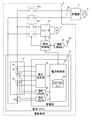
- FIG. 2 is a diagram for explaining a detailed configuration of the battery system 40 mounted on the electric vehicle 3.
- the battery system 40 is connected to the motor 34 via the first relay RY1 and the inverter 35.
- the inverter 35 converts the DC power supplied from the battery system 40 into AC power and supplies it to the motor 34 during power running.
- the AC power supplied from the motor 34 is converted into DC power and supplied to the battery system 40.
- the motor 34 is a three-phase AC motor, and rotates according to the AC power supplied from the inverter 35 during power running.
- the rotational energy due to deceleration is converted into AC power and supplied to the inverter 35.
- the first relay RY1 is a contactor inserted between the wiring connecting the battery system 40 and the inverter 35.
- the vehicle control unit 30 controls the first relay RY1 to be in an on state (closed state) during traveling, and electrically connects the battery system 40 and the power system of the electric vehicle 3.
- the vehicle control unit 30 controls the first relay RY1 to an off state (open state) when the vehicle is not running, and electrically shuts off the power system of the battery system 40 and the electric vehicle 3.
- another type of switch such as a semiconductor switch may be used.
- the battery system 40 can be charged from the commercial power system 9 by connecting to the charger 4 installed outside the electric vehicle 3 with the charging cable 38.
- the charger 4 is connected to the commercial power system 9 and charges the battery system 40 in the electric vehicle 3 via the charging cable 38.
- the second relay RY2 is inserted between the wiring connecting the battery system 40 and the charger 4.
- another type of switch such as a semiconductor switch may be used.
- the management unit 42 of the battery system 40 controls the second relay RY2 to the on state (closed state) before the start of charging, and controls the second relay RY2 to the off state (open state) after the charging is completed.
- alternating current in the case of normal charging and by direct current in the case of quick charging.
- direct current in the case of quick charging.
- alternating current power is converted to direct current power by an AC / DC converter (not shown) inserted between the second relay RY2 and the battery system 40.
- the battery system 40 includes a battery module 41 and a management unit 42, and the battery module 41 includes a plurality of cells E1-En connected in series.
- the battery module 41 may be configured by connecting a plurality of battery modules in series / series / parallel.
- a lithium ion battery cell a nickel hydrogen battery cell, a lead battery cell or the like can be used.
- a lithium ion battery cell nominal voltage: 3.6-3.7V
- the number of cells E1-En in series is determined according to the drive voltage of the motor 34.
- Shunt resistors Rs are connected in series with multiple cells E1-En.
- the shunt resistor Rs functions as a current detection element.
- a Hall element may be used instead of the shunt resistor Rs.
- a plurality of temperature sensors T1 and T2 for detecting the temperatures of the plurality of cells E1-En are installed in the battery module 41.
- One temperature sensor may be installed in the battery module, or one temperature sensor may be installed in each of a plurality of cells.
- a thermistor can be used for the temperature sensors T1 and T2.
- the management unit 42 includes a voltage measurement unit 43, a temperature measurement unit 44, a current measurement unit 45, and a battery control unit 46.
- Each node of the plurality of cells E1-En connected in series and the voltage measuring unit 43 are connected by a plurality of voltage lines.
- the voltage measuring unit 43 measures the voltage of each cell E1-En by measuring the voltage between two adjacent voltage lines.
- the voltage measuring unit 43 transmits the measured voltage of each cell E1-En to the battery control unit 46.
- the voltage measuring unit 43 Since the voltage measuring unit 43 has a high voltage with respect to the battery control unit 46, the voltage measuring unit 43 and the battery control unit 46 are connected by a communication line in an insulated state.
- the voltage measuring unit 43 can be configured by an ASIC (Application Specific Integrated Circuit) or a general-purpose analog front-end IC.
- the voltage measuring unit 43 includes a multiplexer and an A / D converter.
- the multiplexer outputs the voltage between two adjacent voltage lines to the A / D converter in order from the top.
- the A / D converter converts the analog voltage input from the multiplexer into a digital value.
- the temperature measuring unit 44 includes a voltage dividing resistor and an A / D converter.
- the A / D converter sequentially converts a plurality of analog voltages divided by the plurality of temperature sensors T1 and T2 and the plurality of voltage dividing resistors into digital values and outputs the digital values to the battery control unit 46.
- the battery control unit 46 estimates the temperatures of the plurality of cells E1-En based on the digital values. For example, the battery control unit 46 estimates the temperature of each cell E1-En based on the value measured by the temperature sensor most adjacent to each cell E1-En.
- the current measuring unit 45 includes a differential amplifier and an A / D converter.
- the differential amplifier amplifies the voltage across the shunt resistor Rs and outputs it to the A / D converter.
- the A / D converter converts the voltage input from the differential amplifier into a digital value and outputs it to the battery control unit 46.
- the battery control unit 46 estimates the current flowing through the plurality of cells E1-En based on the digital value.
- the temperature measurement unit 44 and the current measurement unit 45 transfer the analog voltage to the battery control unit 46. It may be output to the digital value and converted into a digital value by the A / D converter in the battery control unit 46.
- the battery control unit 46 determines the state of the plurality of cells E1-En based on the voltage, temperature, and current of the plurality of cells E1-En measured by the voltage measurement unit 43, the temperature measurement unit 44, and the current measurement unit 45. to manage.
- the battery control unit 46 and the vehicle control unit 30 are connected by an in-vehicle network.
- the in-vehicle network for example, CAN (Control Area Network) or LIN (Local Area Network) can be used.
- the battery control unit 46 can be configured by a microcomputer and a non-volatile memory (for example, EEPROM, flash memory).
- the SOC-OCV map 46a is held in a microcomputer or non-volatile memory.
- characteristic data of SOC-OCV curves of a plurality of cells E1-En are described.
- the SOC-OCV curves of the plurality of cells E1-En are created in advance by the battery manufacturer and registered in the microcomputer or the non-volatile memory at the time of shipment. The battery maker conducts various tests to derive the SOC-OCV curve of the cells E1-En.
- the battery control unit 46 estimates the SOC, FCC, and SOH of each of the plurality of cells E1-En.
- the battery control unit 46 estimates the SOC by combining the OCV method and the current integration method.
- the OCV method is a method of estimating SOC based on the OCV of each cell E1-En measured by the voltage measuring unit 43 and the characteristic data of the SOC-OCV curve described in the SOC-OCV map 46a.
- the current integration method is a method of estimating SOC based on the OCV at the start of charging / discharging of each cell E1-En and the integrated value of the current measured by the current measuring unit 45. In the current integration method, the measurement error of the current measuring unit 45 accumulates as the charging / discharging time becomes longer. Therefore, it is preferable to use the SOC estimated by the OCV method to correct the SOC estimated by the current integration method.
- the battery control unit 46 estimates the FCC of the cell based on the characteristic data of the SOC-OCV curve described in the SOC-OCV map 46a and the two OCVs of the cell measured by the voltage measurement unit 43. Can be done.
- FIG. 3 is a diagram for explaining an FCC estimation method.
- the battery control unit 46 acquires two OCVs of the cell.
- the battery control unit 46 identifies the two SOCs corresponding to the two voltages with reference to the SOC-OCV curve, and calculates the difference ⁇ SOC between the two SOCs.
- the SOCs of the two points are 20% and 75%, and the ⁇ SOC is 55%.
- the battery control unit 46 can estimate the FCC by calculating the following (Equation 1).
- the battery control unit 46 can estimate the SOH by calculating the following (Equation 2).
- SOH current FCC / initial FCC ... (Equation 2) Further, SOH may be obtained by capacity measurement by complete charge / discharge, or may be obtained by adding storage deterioration and cycle deterioration.
- Storage deterioration can be estimated based on SOC, temperature, and storage deterioration rate.
- Cycle degradation can be estimated based on the SOC range used, temperature, current rate, and cycle degradation rate.
- the storage deterioration rate and the cycle deterioration rate can be derived in advance by experiments or simulations.
- the SOC, temperature, SOC range, and current rate can be determined by measurement.
- the SOH can also be estimated based on the correlation with the internal resistance of the cell.
- the internal resistance can be estimated by dividing the voltage drop generated when a predetermined current is passed through the cell for a predetermined time by the current value.
- the internal resistance is related to decrease as the temperature rises, and increases as the SOH decreases.
- the battery control unit 46 notifies the vehicle control unit 30 of the voltage, current, temperature, SOC, FCC, and SOH of the plurality of cells E1-En via the vehicle-mounted network.
- the vehicle control unit 30 includes operation data of the plurality of cells E1-En including identification information, type information, voltage, current, temperature, SOC, and measurement time of the plurality of cells E1-En, identification information of the electric vehicle 3, and vehicle type. Generate driving data including information. FCC and SOH are not included in the operational data of the plurality of cells E1-En.
- the traveling data may include data such as speed data and traveling position data of the electric vehicle 3.
- the wireless communication unit 36 performs signal processing for wirelessly connecting to the network 5 via the antenna 36a.
- the wireless communication unit 36 wirelessly transmits the travel data acquired from the vehicle control unit 30 to the operator system 2.
- a wireless communication network to which the electric vehicle 3 can be wirelessly connected for example, a mobile phone network (cellular network), a wireless LAN, ETC (Electronic Toll Collection System), DSRC (Dedicated Short Range Communications), V2I (Vehicle-to-Infra) , V2V (Vehicle-to-Wireless) can be used.
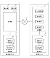
- FIG. 4 is a diagram showing a configuration example of the business operator system 2 and the arithmetic system 1 shown in FIG.
- the operator system 2 includes a processing unit 21, a storage unit 22, a display unit 23, and an operation unit 24.
- the function of the processing unit 21 can be realized by the collaboration of hardware resources and software resources, or only by hardware resources.
- hardware resources CPU, GPU (Graphics Processing Unit), ROM, RAM, ASIC, FPGA (Field Programmable Gate Array), and other LSIs can be used.
- Programs such as operating systems and applications can be used as software resources.
- the storage unit 22 includes a travel data holding unit 221 and a driver data holding unit 222.
- the storage unit 22 includes a non-volatile recording medium such as an HDD (Hard Disk Drive) and an SSD (Solid State Drive), and records various programs and data.
- HDD Hard Disk Drive
- SSD Solid State Drive
- the driving data holding unit 221 holds driving data collected from a plurality of electric vehicles 3 owned by the business operator.
- the driver data holding unit 222 holds data of a plurality of drivers belonging to the business operator. For example, the cumulative mileage of each of the driven electric vehicles 3 is managed for each driver.
- the display unit 23 includes a display such as a liquid crystal display or an organic EL display, and displays an image generated by the processing unit 21.
- the operation unit 24 is a user interface such as a keyboard, a mouse, and a touch panel, and accepts operations by the user of the operator system 2.
- the operator system 2 can provide the operation data of a plurality of electric vehicles 3 held in the travel data holding unit 221 to the calculation system 1.
- This data provision is executed based on the contract between each business operator A and B and the operating entity of the arithmetic system 1.
- This contract may be a contract in which each business operator A or B receives monetary consideration in return for providing data, or a contract in which each business operator A or B receives benefits related to the use of services in return for providing data. May be. Further, each of the business operators A and B may provide the driving data free of charge.
- the business operator system 2 can request the arithmetic system 1 to inspect whether the electric vehicle 3 purchased by the business establishment is equipped with the battery module 41 different from the catalog specifications.
- the inspection service of the mounted battery module 41 may be paid or free of charge. For example, it may be a service that can be used free of charge by a business operator in return for providing data.
- the arithmetic system 1 includes a processing unit 11 and a storage unit 12.
- the processing unit 11 includes a data acquisition unit 111, an extraction unit 112, an estimation unit 113, and a detection unit 114.
- the function of the processing unit 11 can be realized only by the cooperation of the hardware resource and the software resource, or by the hardware resource alone.
- hardware resources CPU, GPU, ROM, RAM, ASIC, FPGA, and other LSIs can be used.
- Programs such as operating systems and applications can be used as software resources.
- the storage unit 12 includes a traveling data holding unit 121 and an SOC-OCV characteristic holding unit 122.
- the storage unit 22 includes a non-volatile recording medium such as an HDD or SSD, and records various programs and data.
- the driving data holding unit 121 holds the driving data of the electric vehicle 3 collected from each of the business operators A and B.
- the SOC-OCV characteristic holding unit 122 holds the SOC-OCV characteristic created by the processing unit 11 based on the collected travel data.
- the SOC-OCV characteristics may be maintained in cell units or in battery module 41 units.
- the traveling data holding unit 121 shall hold the SOC-OCV characteristics of the battery module 41 for each of the same vehicle models.
- the data acquisition unit 111 acquires the travel data of the electric vehicle 3 from the plurality of businesses A and B, and stores the acquired travel data in the travel data holding unit 121.
- the extraction unit 112 extracts a set of SOC and voltage at a plurality of times included in the operation data of the plurality of battery modules 41 held in the travel data holding unit 121 as sample data. At that time, the extraction unit 112 extracts a set of SOC and voltage during a period in which the voltage can be regarded as OCV (that is, a period in which the cell can be regarded as a dormant state).
- a secondary battery is an electrochemical product, and when a charging current flows through a secondary battery, the measured voltage rises non-linearly, and when a discharge current flows through the secondary battery, the measured voltage drops non-linearly.
- the voltage measured when a current is flowing through the secondary battery is a CCV (Closed Circuit Voltage) including an overvoltage component, and is a value deviating from the OCV.
- CCV Current Circuit Voltage
- the measured voltage is about 30 seconds after the end of charging / discharging, and converges to the vicinity of OCV containing no overvoltage component.
- the time required for convergence to the vicinity of OCV varies. For example, in the negative electrode material mixed with silicon, it takes one hour or more to converge in the vicinity of OCV.
- the extraction unit 112 From the set of SOC and voltage at a plurality of times, the extraction unit 112 has a current value of zero and after a predetermined time (for example, 30 seconds) has elapsed from the end of charging / discharging (after the current value becomes zero).
- a predetermined time for example, 30 seconds
- the set of SOC and voltage included in the period may be extracted.
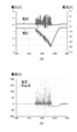
- FIGS. 5 (a)-(b) are diagrams showing an example of driving data.
- FIG. 5A is a diagram showing an example of changes in voltage and current included in the running data for a certain day.
- FIG. 5B is a plot of current measurement points for a certain day.
- the small circles indicate the measurement points of the current measured while the electric vehicle 3 is traveling.
- the large circle mark indicates the measurement point of the current measured while the electric vehicle 3 is stopped. That is, it indicates a resting point where no current is flowing.
- FIGS. 5 (a) and 5 (b) there are many rest points in the travel data, and it is possible to acquire a large number of voltages that can be regarded as OCV from the travel data.
- the extraction unit 112 may also extract a set of SOC and voltage for a period in which the current value of the set value (for example, 1A or 0.1C) or less is the set time (for example, 1 minute) or more and continues. That is, in this case, the period in which the current of the charge / discharge rate of 0.1 C or less or the current of 1 A or less is continued for 1 minute in the battery module 41 is a period that can be regarded as OCV or a period in which the cell can be regarded as a dormant state.
- the current value of the set value for example, 1A or 0.1C
- the set time for example, 1 minute
- the estimation unit 113 generates an approximate curve based on the sample data of a plurality of points extracted by the extraction unit 112, and estimates the SOC-OCV characteristics of the battery module 41.
- the estimation unit 113 stores the estimated SOC-OCV characteristics in the SOC-OCV characteristic holding unit 122.
- the estimation unit 113 may separately generate the SOC-OCV characteristic for charging and the SOC-OCV characteristic for discharging the battery module 41.
- the extraction unit 112 sets the SOC and voltage set for a period that can be regarded as a hibernation state after the charging of the battery module 41 is completed, and an SOC for a period that can be regarded as a hibernation state after the discharge from the battery module 41 is completed. And voltage pairs are extracted separately.
- the estimation unit 113 may estimate the SOC-OCV characteristics based only on the sample data of the battery module 41 whose usage period is shorter than the predetermined period (for example, one year).
- the SOC estimated by the management unit 42 of the electric vehicle 3 has relatively high accuracy when the battery module 41 is close to a new one. As the cell usage period becomes longer, the accuracy of the SOC estimated by the management unit 42 generally decreases. In particular, the management unit 42, which does not have a mechanism for updating the retained SOC-OCV characteristics according to the usage period of the battery module 41, tends to reduce the accuracy of the SOC.
- estimating the SOC-OCV characteristics based only on the sample data of the battery module 41 having a short usage period has higher estimation accuracy of the SOC-OCV characteristics than the estimation based on the sample data of the entire period.
- the SOC-OCV characteristics are estimated based only on the sample data of the cell in which the cumulative value of the charge / discharge current of the battery module 41 is smaller than the predetermined value. You may.
- the SOC-OCV characteristics of the battery module 41 depend on the temperature and the degree of deterioration.
- the extraction unit 112 may classify and extract the sample data of the battery module 41 based on at least one of the temperature classification and the deterioration degree classification.
- the estimation unit 113 may generate the SOC-OCV characteristics of the battery module 41 by mapping into at least one of the temperature classification and the deterioration degree classification based on the sample data classified for each classification. As described above, when the operation data of each battery module 41 includes identification information for uniquely identifying each battery module 41, the usage period of each battery module 41 and the cumulative value of the charge / discharge current are used as the basis. The degree of deterioration of each battery module 41 can be estimated.
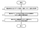
- FIG. 6 is a flowchart showing the flow of the estimation processing of the SOC-OCV characteristics of the battery module 41 by the arithmetic system 1.
- the data acquisition unit 111 acquires the running data (including the voltage, current, SOC, and temperature of the battery module 41) of the electric vehicle 3 from the operator system 2 (S10).
- the data acquisition unit 111 stores the acquired travel data in the travel data holding unit 121.
- the extraction unit 112 extracts a set of SOC and voltage during a period in which the battery module 41 can be regarded as a hibernation state from the travel data held in the travel data holding unit 121 (S11).
- the estimation unit 113 generates an approximate curve based on the extracted plurality of sets of SOCs and voltages, and estimates the SOC-OCV characteristics (S12).
- the estimation unit 113 stores the estimated SOC-OCV characteristics in the SOC-OCV characteristic holding unit 122.
- the catalog states that only one type of battery module 41 is used, another type of battery module 41 may be mounted on the actually purchased electric vehicle 3.
- the catalog states that a ternary lithium-ion battery is used, there are cases where an iron phosphate lithium-ion battery is actually used.
- the battery module 41 having a small capacity may be used.
- the detection unit 114 of the arithmetic system 1 statistically processes a plurality of driving data of the same vehicle type as the inspection target, and inspects whether or not a battery module 41 different from the catalog specifications is mounted.
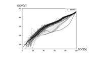
- FIG. 7 is a diagram showing an example of a graph in which a plurality of SOC-OCV characteristics of a battery module 41 mounted on a plurality of electric vehicles 3 of a specific vehicle type are plotted.
- the battery module 41 specified based on the current from the set of SOC and voltage at a plurality of times included in the traveling data is in a hibernation state for each of the electric vehicles 3 of the vehicle type.
- the set of SOC and voltage for a period that can be regarded is extracted as sample data.
- the estimation unit 113 estimates the SOC-OCV characteristics of the battery module 41 mounted on each electric vehicle 3 of the vehicle type based on the extracted sample data. In order to detect the battery module 41 different from the catalog specifications with high accuracy, it is desirable that the SOC-OCV characteristics of a large number of electric vehicles 3 (individuals) of the vehicle type can be collected.
- the detection unit 114 specifies the median value of the plurality of SOC-OCV characteristics.
- the series of the largest black dots shows the median value of a plurality of SOC-OCV characteristics.
- the detection unit 114 calculates the distance between the median value of the SOC-OCV characteristics and each SOC-OCV characteristic. Specifically, the detection unit 114 calculates the distance between the median value of the SOC-OCV characteristic and each SOC-OCV characteristic for each SOC value (for example, every 1%).
- the distance may be an Euclidean distance or a Mahalanobis distance.
- an individual equipped with a battery different from the product specifications is detected based on the distance of each SOC value between the median value of a plurality of SOC-OCV characteristics and each SOC-OCV characteristic.
- An example will be described, but it does not necessarily have to be the median value of a plurality of SOC-OCV characteristics. Specifically, it may be calculated using other representative values such as the average value and the mode value of a plurality of SOC-OCV characteristics. Further, the configuration using representative values such as the median value of a plurality of SOC-OCV characteristics has a feature that even if the product specifications are unknown, it is possible to detect an individual equipped with a battery different from the product specifications.
- the distance between the pre-recorded SOC-OCV characteristic values and each SOC-OCV characteristic for each SOC value. May be configured to calculate.
- various tests can be performed to derive the SOC-OCV curve of the product specifications.
- Mahalanobis distance d means the distance normalized by the standard deviation ⁇ as shown in the following (Equation 3).
- X indicates the average value of the Euclidean distance of each sample.
- ⁇ indicates the standard deviation of the Euclidean distance of each sample.
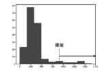
- FIG. 8 is a diagram showing an example of a histogram of the Mahalanobis distance between the median SOC-OCV characteristic and each SOC-OCV characteristic at a certain value of SOC.
- the detection unit 114 determines that a value exceeding the threshold value is an outlier. For example, a value of 3 ⁇ may be used for the threshold value. If the distribution is normal, 99.7% is within 3 ⁇ , so values exceeding 3 ⁇ can be determined as outliers.
- the optimum threshold value may be adaptively changed by learning.
- the detection unit 114 calculates outliers for each SOC value, and determines that the SOC-OCV characteristic including the outliers is the electric vehicle 3 equipped with the battery module 41 different from the catalog specifications.
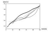
- FIG. 9 is a graph showing a graph in which the median SOC-OCV characteristics and the SOC-OCV characteristics including outliers are left from the graph of FIG. 7.
- the median value of the SOC-OCV characteristic is an upward convex curve
- the SOC-OCV characteristic including an outlier is a downward convex curve. That is, the SOC-OCV characteristic of the regular battery module 41 described in the catalog of a specific vehicle model is an upward convex curve, and the illegal battery module 41 not described in the catalog but installed in the vehicle model is illegal. It is presumed that the SOC-OCV characteristic of is a downwardly convex curve.
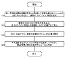
- FIG. 10 is a flowchart showing the flow of a first processing example for detecting whether or not a battery module 41 different from the catalog specifications by the arithmetic system 1 is mounted.
- the estimation unit 113 estimates the SOC-OCV characteristics of the plurality of battery modules 41 mounted on the vehicle model based on the traveling data of the plurality of battery modules 41 acquired from the plurality of electric vehicles 3 of the same vehicle model (the estimation unit 113). S20).
- the detection unit 114 calculates the distance between the median value of the plurality of SOC-OCV characteristics and each SOC-OCV characteristic for each SOC value (S21).
- the detection unit 114 identifies outliers from a plurality of distances for each SOC value (S22).
- the detection unit 114 determines that the electric vehicle 3 that has transmitted the SOC-OCV characteristics including the outliers is the electric vehicle 3 equipped with the battery module 41 that is different from the product specifications not described in the catalog (S23).
- outliers of the distance from the median were searched for in the entire SOC range (0-100%).
- the SOC range for searching for outliers of the distance from the median may be narrowed down to a predetermined SOC range.
- outliers may be searched for in the range of 40-70%.
- the SOC range may have a large OCV difference.
- the OCV difference tends to be large at the central portion of the SOC range, and the OCV difference tends to be small at both ends of the SOC range.
- the SOC range in which OCV differences are likely to occur may be learned for each vehicle type. As the number of samples increases, the tendency of the SOC range in which OCV differences are likely to occur can be grasped, and the calculation amount can be reduced by narrowing the range for searching outliers to the SOC range.
- a battery module 41 different from the catalog specifications is installed based on the relationship between the SOC and OCV of one point of the plurality of battery modules 41 acquired from the plurality of electric vehicles 3 of the same vehicle type. A method of detecting whether or not it is present is effective.
- FIG. 11 is a flowchart showing the flow of a second processing example for detecting whether or not a battery module 41 different from the catalog specifications by the arithmetic system 1 is mounted.
- the estimation unit 113 Based on the running data of the plurality of battery modules 41 acquired from the plurality of electric vehicles 3 of the same vehicle model, the estimation unit 113 has a specific value (for example, for example, SOC) of the plurality of battery modules 41 mounted on the vehicle model. , 50%) to identify the SOC and OCV (S30).
- the detection unit 114 calculates the median value of a plurality of OCVs when the SOC is a specific value and the distance between each OCV (S31).
- the detection unit 114 identifies outliers from a plurality of distances (S32).
- the detection unit 114 determines that the electric vehicle 3 that has transmitted the OCV including the outliers is the electric vehicle 3 equipped with the battery module 41 that is different from the product specifications (S33).
- the estimation unit 113 generates an approximate curve based on the sample data of a plurality of points and estimates the SOC-OCV characteristics for each battery module 41. If the OCV value when the SOC is a specific value can be acquired for each battery module 41, it is possible to detect the electric vehicle 3 equipped with the battery module 41 different from the catalog specifications.
- the amount of calculation can be significantly reduced as compared with the first processing example, and the processing speed can be increased.
- the judgment accuracy may decrease. Therefore, in the third processing example, the angle is added to the determination standard in addition to the distance.
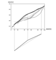
- a method of detecting whether or not a battery module 41 different from the catalog specifications is mounted will be described using three points showing the relationship between SOC and OCV.
- FIG. 12 is a diagram showing the shape of a line connecting the three points of the median.
- three points of OCV are connected when the SOC is 10%, 50%, and 90%.
- the three points for extracting OCV are not limited to these numerical values, but one point is extracted from each of the low SOC region, the medium SOC region, and the high SOC region so that the overall shape can be easily grasped. Is preferable.
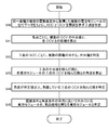
- FIG. 13 is a flowchart showing the flow of a third processing example for detecting whether or not a battery module 41 different from the catalog specifications by the arithmetic system 1 is mounted.
- the estimation unit 113 determines the relationship between the SOC and the OCV for each of the plurality of battery modules 41 mounted on the vehicle model.
- the three points shown are specified (S40).
- the median value of a plurality of OCVs and the distance between each OCV are calculated for each of the three SOCs (S41).
- the detection unit 114 identifies outliers from a plurality of distances for each of the three SOCs (S42).
- the detection unit 114 calculates the angle between the line connecting the medians of the three OCVs and the line connecting the three OCVs of each battery module 41 (S43).
- the detection unit 114 identifies a line connecting three OCVs whose angles are equal to or greater than a predetermined value and deviates from each other (S44). For example, at least one of the angle difference on the low SOC side from the line connecting the medians of the three OCVs and the angle difference on the high SOC side from the line connecting the medians of the three OCVs is 10.
- the detection unit 114 sets the line connecting the median values of the three OCVs and the line connecting the three OCVs of the target battery module 41 as a line having different attributes. judge.
- the detection unit 114 determines that the electric vehicle 3 that has transmitted the three points of SOC and OCV that are out of alignment in both the distance condition and the angle condition is the electric vehicle 3 equipped with the battery module 41 that is different from the product specifications ( S45).
- the detection unit 114 may narrow down the sample for which the angle is compared to the data including the outlier in the distance from the median. That is, the detection unit 114 determines that the data that does not include the outliers at the distance from the median is the data of the regular battery module 41 described in the catalog without comparing the angles.
- the threshold value for specifying the outlier in the distance from the median may be set loosely. At that time, the detection unit 114 may narrow down the sample for which the angle is compared to a part of the data exceeding the threshold value and close to the threshold value. The detection unit 114 unconditionally determines that the remaining data far from the threshold value is the battery module 41 different from the product specifications.
- step S44 it was determined whether or not the attributes differ depending on whether or not the angle difference is equal to or greater than a predetermined value, but it is determined whether or not the attributes differ depending on whether the line connecting the three points is upwardly convex or downwardly convex. You may. In the example shown in FIG. 12, since the line connecting the medians of the three OCVs is upwardly convex, the detection unit 114 is a normal battery when the line connecting the three target OCVs is upwardly convex. It is determined to be the data of the module 41, and if it is downwardly convex, it is determined to be the data of the battery module 41 different from the product specifications.
- an example of detecting whether or not a battery module 41 different from the catalog specifications is mounted has been described by using three points showing the relationship between SOC and OCV.
- the two points for extracting OCV are one point each from the low SOC region and the medium SOC region, or one point each from the medium SOC region and the high SOC region.
- data of each battery module 41 is collected from a plurality of electric vehicles 3 of the same vehicle type, and the collected data is cluster-analyzed by statistical processing to obtain a battery different from the catalog specifications.
- the electric vehicle 3 on which the module 41 is mounted can be easily detected. It can be detected regardless of the battery manufacturer or the type of battery.
- the running data of the electric vehicle 3 it is sufficient to have the running data of the electric vehicle 3, and no special inspection device is required. It is not necessary to add a new function to the management unit 42 of the battery system 40 of each electric vehicle 3. Moreover, it is not necessary to acquire the characteristics of various batteries in advance. Therefore, it is possible to reduce the financial and time costs required for system construction and operation. For example, no maintenance time is required to add battery characteristics.
- the battery module 41 different from the catalog specifications is mounted based on the relationship between the SOC and the OCV at least one point for each battery module 41.
- Internal resistance is also dependent on SOC. The relationship between the SOC and the internal resistance differs depending on the type of battery, but in general, the internal resistance tends to increase at both ends of the SOC range.
- the internal resistance R can be calculated by the following (Equation 4) and the following (Equation 5).
- the internal resistance R can be estimated by substituting the voltage measured during traveling as CCVd, the current as Id, and the voltage measured immediately before the start of traveling as OCVd in the above (Equation 4).
- the electric vehicle 3 may be a two-wheeled electric motorcycle (electric scooter) or an electric bicycle. Further, the electric vehicle 3 also includes a low-speed electric vehicle 3 such as a golf cart and a land car used in a shopping mall, an entertainment facility, or the like.
- the product on which the battery module 41 is mounted is not limited to the electric vehicle 3.
- electric mobile bodies such as electric vessels, railroad vehicles, and multicopters (drones) are also included.
- Products equipped with the battery module 41 also include stationary power storage systems and consumer electronic devices (smartphones, notebook PCs, etc.). In either case, by collecting the operation data of the battery module 41 for the same product, it is possible to detect whether or not each individual is equipped with the battery module 41 different from the product specifications.
- the embodiment may be specified by the following items.
- Operational data including at least the voltage of the batteries (E1, 41) mounted on the same product (3) and SOC (State Of Charge) are acquired from a plurality of individuals of the product (3) via the network (5).
- Data acquisition unit (111) A detector (114) that statistically processes a plurality of acquired operational data and detects an individual equipped with a battery (E1, 41) different from the specifications of the product (3).
- An arithmetic system (1) characterized in that it is provided with.
- the battery (E1, 41) may be the cell E1 or the module 41.
- the data acquisition unit (111) acquires operational data including at least the voltage, current, and SOC at a plurality of times measured on the individual side of the product (3) from each individual.
- the arithmetic system (1) is From the set of SOC and voltage at a plurality of times included in the plurality of operational data, the set of SOC and voltage during the period in which the battery (E1, 41) specified based on the current can be regarded as a dormant state is obtained.
- An estimation unit (113) that estimates the SOC-OCV (Open Circuit Voltage) characteristics of a plurality of batteries (E1, 41) mounted on a plurality of individuals of the product (3) based on the extracted sample data.
- the arithmetic system (1) according to item 2, further comprising.
- the product (3) equipped with a battery (E1, 41) different from the catalog specifications based on the SOC-OCV characteristics estimated based on the operational data acquired from the individual product (3). Can be detected easily and with high accuracy.
- the detection unit (114) is a battery (E1, 41) different from the specifications of the product (3) based on the degree of deviation from the representative value of the SOC-OCV characteristics of the plurality of batteries (E1, 41).
- the representative value may be, for example, any of the median value, the average value, and the mode value.
- the product (3) equipped with the battery (E1, 41) different from the catalog specifications can be detected easily and with high accuracy. Can be done.
- the detection unit (114) is a battery (E1, 41) different from the specification of the product (3) based on the degree of deviation from the value recorded in advance as the SOC-OCV characteristic of the specification of the product (3). ) Is mounted on the arithmetic system (1) according to item 2, which is characterized by detecting an individual.
- the product (E1, 41) on which the battery (E1, 41) different from the catalog specification is mounted ( 3) can be detected easily and with high accuracy.
- the detection unit (114) uses data in a predetermined SOC range in the SOC-OCV characteristics of the plurality of batteries (E1, 41), and the battery (E1, 41) different from the specifications of the product (3).
- the amount of calculation can be reduced as compared with the case of using the data of the entire SOC range.
- the data acquisition unit (111) acquires operational data including at least one time voltage, current, and SOC measured on each individual side of the product (3) from each individual.
- the arithmetic system (1) is From at least one SOC and voltage set included in each of the plurality of operational data, an SOC and voltage set for a period in which the battery (E1, 41) specified based on the current can be regarded as a dormant state is obtained.
- An extraction unit (112) to be extracted as sample data, and Based on the extracted sample data, the SOC of at least one specific value of the plurality of batteries (E1, 41) mounted on the plurality of individuals of the product (3), and the OCV (Open Circuit Voltage).
- the detection unit (114) is a battery (E1) different from the specifications of the product (3) based on the relationship between the SOC of at least one specific value of the plurality of batteries (E1, 41) and the OCV. 41)
- the detection unit (114) has a plurality of representative values indicating the relationship between the SOC and OCV of the plurality of batteries (E1, 41) and a plurality of points indicating the relationship between the SOC and OCV of each battery (E1, 41). Degree of deviation of the distance from each value of, and the degree of deviation between the line connecting the representative values of the plurality of points and the line connecting the multiple points indicating the relationship between the SOC and OCV of each battery (E1, 41).
- the detection unit (114) has a plurality of points indicating the relationship between the SOC and OCV of the specifications of the product (3) and each value at a plurality of points indicating the relationship between the SOC and OCV of each battery (E1, 41).
- the data acquisition unit (111) acquires operational data including at least one time voltage, current, and SOC measured on each individual side of the product (3) from each individual.
- the arithmetic system (1) is Based on the plurality of operational data, the relationship between the SOC of at least one specific value of the plurality of batteries (E1, 41) mounted on the plurality of individuals of the product (3) and the internal resistance is determined. Further equipped with a specific part (113) to be specified,
- the detection unit (114) is a battery (3) different from the specifications of the product (3) based on the relationship between the SOC of at least one specific value of the plurality of batteries (E1, 41) and the internal resistance.
- the arithmetic system (1) according to item 1, wherein an individual equipped with E1, 41) is detected.
- Operational data including at least the voltage of the batteries (E1, 41) mounted on the same product (3) and SOC (State Of Charge) are acquired from a plurality of individuals of the product (3) via the network (5). Steps to do and A step of statistically processing a plurality of acquired operational data to detect an individual equipped with a battery (E1, 41) different from the specifications of the product (3).
- Operational data including at least the voltage of the batteries (E1, 41) mounted on the same product (3) and SOC (State Of Charge) are acquired from a plurality of individuals of the product (3) via the network (5).
- processing to do A process of statistically processing a plurality of acquired operational data to detect an individual equipped with a battery (E1, 41) different from the specifications of the product (3).
- 1 Computation system 2 Operator system, E1-En cell, T1, T2 temperature sensor, RY1, RY2 relay, 3 Electric vehicle, 4 Charger, 5 Network, 11 Processing unit, 111 Data acquisition unit, 112 Extraction unit, 113 Estimator, 114 Detection unit, 12 Storage unit, 121 Driving data holding unit, 122 SOC-OCV characteristic holding unit, 21 Processing unit, 22 Storage unit, 221 Driving data holding unit, 222 Driver data holding unit, 23 Display unit, 24 Operation unit , 30 Vehicle control unit, 34 Motor, 35 Inverter, 36 Wireless Communication Unit, 36a Antenna, 38 Charging Cable, 40 Battery System, 41 Battery Module, 42 Management Department, 43 Voltage measuring unit, 44 Temperature measuring unit, 45 Current measuring unit, 46 Battery control unit, 46a SOC-OCV map.
Landscapes
- Business, Economics & Management (AREA)
- General Physics & Mathematics (AREA)
- Physics & Mathematics (AREA)
- Engineering & Computer Science (AREA)
- Strategic Management (AREA)
- Marketing (AREA)
- Economics (AREA)
- General Business, Economics & Management (AREA)
- Human Resources & Organizations (AREA)
- Theoretical Computer Science (AREA)
- General Chemical & Material Sciences (AREA)
- Entrepreneurship & Innovation (AREA)
- Manufacturing & Machinery (AREA)
- Tourism & Hospitality (AREA)
- Electrochemistry (AREA)
- Chemical Kinetics & Catalysis (AREA)
- Chemical & Material Sciences (AREA)
- Quality & Reliability (AREA)
- General Health & Medical Sciences (AREA)
- Primary Health Care (AREA)
- Health & Medical Sciences (AREA)
- Finance (AREA)
- Development Economics (AREA)
- Accounting & Taxation (AREA)
- Operations Research (AREA)
- Secondary Cells (AREA)
- Tests Of Electric Status Of Batteries (AREA)
- Charge And Discharge Circuits For Batteries Or The Like (AREA)
Priority Applications (4)
| Application Number | Priority Date | Filing Date | Title |
|---|---|---|---|
| JP2022535020A JP7656839B2 (ja) | 2020-07-08 | 2021-06-25 | 演算システム、電池の検査方法、及び電池の検査プログラム |
| CN202180047888.2A CN115769413A (zh) | 2020-07-08 | 2021-06-25 | 运算系统、电池的检查方法以及电池的检查程序 |
| US18/002,288 US20230236251A1 (en) | 2020-07-08 | 2021-06-25 | Arithmetic system, battery inspection method, and battery inspection program |
| EP21837215.9A EP4181265B1 (en) | 2020-07-08 | 2021-06-25 | Arithmetic system, battery inspection method, and battery inspection program |
Applications Claiming Priority (2)
| Application Number | Priority Date | Filing Date | Title |
|---|---|---|---|
| JP2020-117734 | 2020-07-08 | ||
| JP2020117734 | 2020-07-08 |
Publications (1)
| Publication Number | Publication Date |
|---|---|
| WO2022009696A1 true WO2022009696A1 (ja) | 2022-01-13 |
Family
ID=79553065
Family Applications (1)
| Application Number | Title | Priority Date | Filing Date |
|---|---|---|---|
| PCT/JP2021/024121 Ceased WO2022009696A1 (ja) | 2020-07-08 | 2021-06-25 | 演算システム、電池の検査方法、及び電池の検査プログラム |
Country Status (5)
| Country | Link |
|---|---|
| US (1) | US20230236251A1 (cg-RX-API-DMAC7.html) |
| EP (1) | EP4181265B1 (cg-RX-API-DMAC7.html) |
| JP (1) | JP7656839B2 (cg-RX-API-DMAC7.html) |
| CN (1) | CN115769413A (cg-RX-API-DMAC7.html) |
| WO (1) | WO2022009696A1 (cg-RX-API-DMAC7.html) |
Cited By (1)
| Publication number | Priority date | Publication date | Assignee | Title |
|---|---|---|---|---|
| EP4312299A3 (en) * | 2022-07-27 | 2024-06-12 | Zhejiang Zeekr Intelligent Technology Co., Ltd. | Consistency evaluation method for vehicle battery cell, device, equipment and storage |
Families Citing this family (5)
| Publication number | Priority date | Publication date | Assignee | Title |
|---|---|---|---|---|
| JP7372295B2 (ja) * | 2021-09-30 | 2023-10-31 | 横河電機株式会社 | 診断装置、診断方法及び診断プログラム |
| US20230268753A1 (en) * | 2022-02-21 | 2023-08-24 | Lenovo (United States) Inc. | Intelligent battery charging based on history |
| US20240286524A1 (en) * | 2023-02-23 | 2024-08-29 | GM Global Technology Operations LLC | High-voltage electrical systems pairing solid-state relays with electromechanical contactors for galvanic disconnect |
| CN117473396B (zh) * | 2023-11-23 | 2024-08-02 | 湖南盈旺智慧能源科技有限公司 | 一种基于深度学习的新能源汽车智能电池管理系统 |
| FR3168980A1 (fr) * | 2024-11-26 | 2026-05-29 | Stellantis Auto Sas | Procede de diagnostic d’un systeme de stockage d’energie permettant la detection d’une erreur d’assemblage |
Citations (4)
| Publication number | Priority date | Publication date | Assignee | Title |
|---|---|---|---|---|
| JPH09133741A (ja) | 1995-11-10 | 1997-05-20 | Tokyo Eletec Kk | 電池不良判定装置 |
| JP2010019664A (ja) | 2008-07-10 | 2010-01-28 | Nippon Soken Inc | 電池劣化検出装置および方法 |
| JP2018116839A (ja) * | 2017-01-18 | 2018-07-26 | 株式会社ダイヘン | 管理システム、非接触電力供給システム、及び非接触電力供給システムを管理する方法 |
| WO2020045033A1 (ja) * | 2018-08-28 | 2020-03-05 | 本田技研工業株式会社 | 提示装置、提示方法、及びプログラム |
Family Cites Families (11)
| Publication number | Priority date | Publication date | Assignee | Title |
|---|---|---|---|---|
| US7554296B2 (en) * | 2005-02-14 | 2009-06-30 | Denso Corporation | Method and apparatus for detecting charged state of secondary battery based on neural network calculation |
| BRPI0809518A2 (pt) * | 2007-03-26 | 2016-03-15 | Gillette Co | dispositivo e método de carregador adaptativo |
| JP5556740B2 (ja) * | 2010-10-28 | 2014-07-23 | Smk株式会社 | 情報提供装置、情報提供サーバおよび車両支援システム |
| US9145893B2 (en) * | 2011-06-08 | 2015-09-29 | Bendix Commercial Vehicle Systems Llc | Current control via speed control for driving screw compressor under cold conditions |
| JP6674139B2 (ja) * | 2016-06-07 | 2020-04-01 | 日立化成株式会社 | 車両およびその電池状態検知システム |
| JP6983227B2 (ja) * | 2017-03-31 | 2021-12-17 | 三菱電機株式会社 | 蓄電池状態推定装置 |
| US10312699B2 (en) * | 2017-07-31 | 2019-06-04 | Robert Bosch Gmbh | Method and system for estimating battery open cell voltage, state of charge, and state of health during operation of the battery |
| KR20190047779A (ko) * | 2017-10-30 | 2019-05-09 | 현대자동차주식회사 | 클라우드 서버, 차량 및 차량의 제어방법 |
| KR102634816B1 (ko) * | 2017-12-21 | 2024-02-07 | 삼성전자주식회사 | 배터리의 전하 균형을 탐지하는 배터리 모니터링 장치 및 방법 |
| JP7153196B2 (ja) * | 2018-12-26 | 2022-10-14 | トヨタ自動車株式会社 | 電池特性評価装置、および電池特性評価方法 |
| KR102676246B1 (ko) * | 2019-12-17 | 2024-06-19 | 현대자동차주식회사 | 차량용 배터리 교체 진단 장치 및 그의 배터리 교체 진단 방법 |
-
2021
- 2021-06-25 US US18/002,288 patent/US20230236251A1/en active Pending
- 2021-06-25 JP JP2022535020A patent/JP7656839B2/ja active Active
- 2021-06-25 WO PCT/JP2021/024121 patent/WO2022009696A1/ja not_active Ceased
- 2021-06-25 CN CN202180047888.2A patent/CN115769413A/zh active Pending
- 2021-06-25 EP EP21837215.9A patent/EP4181265B1/en active Active
Patent Citations (4)
| Publication number | Priority date | Publication date | Assignee | Title |
|---|---|---|---|---|
| JPH09133741A (ja) | 1995-11-10 | 1997-05-20 | Tokyo Eletec Kk | 電池不良判定装置 |
| JP2010019664A (ja) | 2008-07-10 | 2010-01-28 | Nippon Soken Inc | 電池劣化検出装置および方法 |
| JP2018116839A (ja) * | 2017-01-18 | 2018-07-26 | 株式会社ダイヘン | 管理システム、非接触電力供給システム、及び非接触電力供給システムを管理する方法 |
| WO2020045033A1 (ja) * | 2018-08-28 | 2020-03-05 | 本田技研工業株式会社 | 提示装置、提示方法、及びプログラム |
Non-Patent Citations (1)
| Title |
|---|
| See also references of EP4181265A4 |
Cited By (2)
| Publication number | Priority date | Publication date | Assignee | Title |
|---|---|---|---|---|
| EP4312299A3 (en) * | 2022-07-27 | 2024-06-12 | Zhejiang Zeekr Intelligent Technology Co., Ltd. | Consistency evaluation method for vehicle battery cell, device, equipment and storage |
| JP7634611B2 (ja) | 2022-07-27 | 2025-02-21 | 浙江極▲け▼智能科技有限公司 | 車両電池セル整合性評価方法、装置、機器及び記憶媒体 |
Also Published As
| Publication number | Publication date |
|---|---|
| JPWO2022009696A1 (cg-RX-API-DMAC7.html) | 2022-01-13 |
| JP7656839B2 (ja) | 2025-04-04 |
| EP4181265A1 (en) | 2023-05-17 |
| CN115769413A (zh) | 2023-03-07 |
| US20230236251A1 (en) | 2023-07-27 |
| EP4181265A4 (en) | 2024-01-03 |
| EP4181265B1 (en) | 2025-03-05 |
Similar Documents
| Publication | Publication Date | Title |
|---|---|---|
| JP7685729B2 (ja) | 演算システム、電池特性推定方法、及び電池特性推定プログラム | |
| JP7620939B2 (ja) | 電池管理装置、演算システム、電池の劣化予測方法、及び電池の劣化予測プログラム | |
| JP7656839B2 (ja) | 演算システム、電池の検査方法、及び電池の検査プログラム | |
| JP7702629B2 (ja) | 演算システム、電池の劣化予測方法、及び電池の劣化予測プログラム | |
| JP7156373B2 (ja) | 電池管理装置、電池情報処理システム、及び電池情報処理方法 | |
| EP4020350A1 (en) | Management system, management program, and electric vehicle | |
| EP4316894A1 (en) | Remaining capacity notification device, remaining capacity notification method, and remaining capacity notification program | |
| JP7839970B2 (ja) | 劣化判定システム、劣化判定方法、および劣化判定プログラム | |
| CN115267552A (zh) | 车辆电池健康状态评估方法、装置、设备及存储介质 | |
| EP4675888A1 (en) | Battery analysis system, battery analysis method, battery analysis program, and storage medium with battery analysis program recorded therein | |
| CN104535935B (zh) | 一种动力电池组的容量检测方法及装置 | |
| CN118541895A (zh) | 电池异常检测系统、电池异常检测方法以及电池异常检测程序 | |
| WO2023176102A1 (ja) | 電池状態分析システム、電池状態分析方法、及び電池状態分析プログラム | |
| CN108810816B (zh) | 蓄电装置的信息收集系统 | |
| US20250216470A1 (en) | Battery analysis system, battery analysis method, and non-transitory computer-readable recording medium | |
| WO2024157509A1 (ja) | 車両利用状況推定システム、車両利用状況推定方法および車両利用状況推定プログラム | |
| CN120530331A (zh) | 电池异常检测系统、电池异常检测方法、电池异常检测程序以及记载有电池异常检测程序的记录介质 |
Legal Events
| Date | Code | Title | Description |
|---|---|---|---|
| 121 | Ep: the epo has been informed by wipo that ep was designated in this application |
Ref document number: 21837215 Country of ref document: EP Kind code of ref document: A1 |
|
| ENP | Entry into the national phase |
Ref document number: 2022535020 Country of ref document: JP Kind code of ref document: A |
|
| WWE | Wipo information: entry into national phase |
Ref document number: 202347006154 Country of ref document: IN |
|
| NENP | Non-entry into the national phase |
Ref country code: DE |
|
| ENP | Entry into the national phase |
Ref document number: 2021837215 Country of ref document: EP Effective date: 20230208 |