WO2022009380A1 - Dispositif serveur, système de gestion d'entrée/sortie, procédé de commande de dispositif serveur et support d'enregistrement - Google Patents
Dispositif serveur, système de gestion d'entrée/sortie, procédé de commande de dispositif serveur et support d'enregistrement Download PDFInfo
- Publication number
- WO2022009380A1 WO2022009380A1 PCT/JP2020/026835 JP2020026835W WO2022009380A1 WO 2022009380 A1 WO2022009380 A1 WO 2022009380A1 JP 2020026835 W JP2020026835 W JP 2020026835W WO 2022009380 A1 WO2022009380 A1 WO 2022009380A1
- Authority
- WO
- WIPO (PCT)
- Prior art keywords
- visitor
- user
- information
- server device
- search request
- Prior art date
Links
Images


Classifications
-
- G—PHYSICS
- G06—COMPUTING; CALCULATING OR COUNTING
- G06Q—INFORMATION AND COMMUNICATION TECHNOLOGY [ICT] SPECIALLY ADAPTED FOR ADMINISTRATIVE, COMMERCIAL, FINANCIAL, MANAGERIAL OR SUPERVISORY PURPOSES; SYSTEMS OR METHODS SPECIALLY ADAPTED FOR ADMINISTRATIVE, COMMERCIAL, FINANCIAL, MANAGERIAL OR SUPERVISORY PURPOSES, NOT OTHERWISE PROVIDED FOR
- G06Q10/00—Administration; Management
- G06Q10/10—Office automation; Time management
Definitions
- the present invention relates to a server device, an entrance / exit management system, a control method for the server device, and a storage medium.
- Patent Document 1 describes that it provides a system that can confirm the seating status of a user without moving to the seat position.
- the system disclosed in Patent Document 1 includes a user terminal and a server.
- a camera is provided in the user terminal.
- the user terminal detects the user's face based on the input image from the camera, determines whether or not the user is present, and transmits the attendance information indicating the determination result to the server.
- the server stores the attendance information transmitted from each user terminal. Further, when the server receives a request for confirmation of the user's presence information from the terminal of another user, the server transmits the stored presence information to the terminal of the other user.
- employees belonging to a specific department may use one free address floor, but many employees in different departments may use the floor.
- the present invention contributes to the ability of a visitor to easily determine whether or not to visit a person while grasping the position of the person who wishes to visit, a server device, an entrance / exit management system, a control method for the server device, and a method for controlling the server device.
- the main purpose is to provide a storage medium.
- the visit is made from the visitor management database that stores the position information and the date and time of the visitor in the restricted area and the authentication terminal that controls the entry of the visitor into the restricted area.
- Receiving unit that receives the search request of the visitor who wishes to visit, and the staying time of the visitor corresponding to the visitor among the visitors stored in the visitor management database according to the search request.
- a server device is provided, comprising a search request processing unit for calculating the above, and a transmission unit for transmitting the position information of the visitor and the calculated staying time to the authentication terminal.
- the server device includes an authentication terminal that controls the entrance of a visitor to the restricted area and a server device connected to the authentication terminal, and the server device is an entry to the restricted area.
- the visitor receives a search request for a visitor who wishes to visit from the visitor management database that stores the position information of the person and the date and time of admission, and the authentication terminal.
- the search request processing unit that calculates the staying time of the visitors corresponding to the visitor among the visitors stored in the visitor management database, the position information of the visitor, and the calculated stay time are described above.
- An entrance / exit management system is provided, which includes a transmission unit for transmitting to an authentication terminal.
- the server device provided with the visitor management database that stores the position information of the visitors in the restricted area and the entry date and time, from the authentication terminal that controls the entrance of the visitor to the restricted area.
- the visitor receives a search request for a visitor who wishes to visit, and according to the search request, the staying time of the visitor corresponding to the visitor among the visitors stored in the visitor management database is determined.
- a control method of a server device that calculates and transmits the position information of the visitor and the calculated staying time to the authentication terminal.
- a computer mounted on a server device having a visitor management database for storing the location information of visitors in the restricted area and the date and time of entry can be used to allow visitors to enter the restricted area.
- a computer-readable program that stores a program for executing a process of calculating the staying time of a visitor and a process of transmitting the position information of the visitor and the calculated staying time to the authentication terminal.
- a storage medium is provided.
- a server device contributes to the ability of a visitor to easily determine whether or not to visit a person while grasping the position of the person who wants to visit the person.
- a method of controlling the device and a storage medium are provided.
- the effect of the present invention is not limited to the above. According to the present invention, other effects may be produced in place of or in combination with the effect.
- the server device 100 includes a visitor management database 101, a receiving unit 102, a search request processing unit 103, and a transmitting unit 104 (see FIG. 1).
- the visitor management database 101 stores the location information and the date and time of entry of the visitors in the restricted area.
- the receiving unit 102 receives a search request for a visitor who the visitor wishes to visit from the authentication terminal that controls the visitor's entry into the restricted area.
- the search request processing unit 103 calculates the staying time of the visitors corresponding to the visitor among the visitors stored in the visitor management database 101 according to the search request.
- the transmission unit 104 transmits the location information of the visitor and the calculated stay time to the authentication terminal.
- the server device 100 refers to the visitor management database 101, acquires the location information of the person whom the visitor wishes to visit, and calculates the staying time.
- the server device 100 transmits the location information and the staying time of the visitor to the authentication terminal.
- the authentication terminal displays so that the visitor can grasp the position and staying time of the visitor. As a result, the visitor can easily determine whether or not to visit the visitor in consideration of the staying time while grasping the position of the person who wishes to visit.
- FIG. 2 is a diagram showing an example of a schematic configuration of an entrance / exit management system according to the first embodiment.
- the entrance / exit management system includes an authentication terminal 10 and a server device 20.
- the entrance / exit management system according to the first embodiment manages entrance / exit for users of a free address floor (hereinafter, also simply referred to as a floor).
- At least one camera device 30 is installed on the floor shown in FIG.
- the camera device 30 is installed so as to give a bird's-eye view of the entire floor.
- one camera device 30 is shown in FIG. 2, when a plurality of camera devices 30 are required to obtain an image overlooking the entire floor, a number of camera devices 30 that achieve the purpose are installed. Will be done.
- FIG. 2 illustrates the connection line between the authentication terminal 10 and the server device 20, other components (for example, the camera device 30) are also connected to the server device 20. Further, a stationary PC (Personal Computer) installed on the floor is also connected to the server device 20.
- PC Personal Computer
- the server device 20 may be installed in the same building as the free address floor, or may be installed on the network (on the cloud).
- the authentication terminal 10 is a terminal installed at the entrance of the free address floor.
- the authentication terminal 10 is connected to the gate 40.
- the authentication terminal 10 opens the gate 40 and permits the visitor to use the free address floor.
- the authentication terminal 10 is a terminal that controls the entrance of a visitor to a restricted area (free address floor) where the users who can enter are restricted (limited).
- the server device 20 is a device that manages users on the floor.
- the server device 20 executes an authentication process using the visitor's biometric information (for example, a face image) acquired via the authentication terminal 10.
- the server device 20 notifies the authentication terminal 10 of the result of the authentication process.
- the server device 20 When the server device 20 succeeds in authenticating the visitor, the server device 20 manages the successful authentication person as a floor visitor (resident). The server device 20 manages the visitors in the free address flow by using a database (a visitor management database described later). The server device 20 also manages the entrance date and time (authentication time) of the visitors.
- the server device 20 manages the positions of users (floor visitors, residents) on the floor.
- the server device 20 grasps the position of each user in real time by any means.
- the server device 20 may acquire location information from a terminal (a terminal such as a smartphone) possessed by the user and grasp the position of the user.
- the terminal possessed by the user may receive a GPS signal from a GPS (Global Positioning System) satellite, perform positioning, and generate position information including the latitude, longitude, and altitude of the own device.
- GPS Global Positioning System
- the server device 20 may detect the position of the user by analyzing the image obtained from the camera device 30.
- the server device 20 grasps the position of the user by analyzing the image obtained from the camera device 30 will be described.
- the server device 20 updates the position of the visitors stored in the visitor management database in real time.
- Visitors may wish to meet with users on the floor (meetings, meetings).
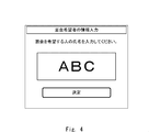
- the visitor inputs information about a person who wishes to visit (hereinafter referred to as a visitor) after the authentication by the authentication terminal 10 is successful.
- the authentication terminal 10 confirms the visitor's intention (whether or not the visitor wishes to meet with another user) using a GUI (Graphical User Interface) as shown in FIG.
- GUI Graphic User Interface
- the authentication terminal 10 finds that the visitor has an intention to meet with another user, the authentication terminal 10 accepts the visitor's operation using the GUI as shown in FIG.
- a visitor who comes into contact with the screen as shown in FIG. 4 inputs the name of the person who wishes to visit in the character input area.
- the authentication terminal 10 transmits the name of the person who wishes to visit the visitor acquired by the GUI as shown in FIG. 4 to the server device 20.
- the authentication terminal 10 includes an input / output device in which a liquid crystal panel and a touch panel are integrated, and uses the input / output device to display a GUI and accept user operations.
- the server device 20 identifies the position of the visitor based on the information (name of the visitor) acquired from the authentication terminal 10, and notifies the authentication terminal 10 of the specified position.
- the authentication terminal 10 uses the acquired information to display the position of the person who wants to visit (the position of the person who wants to visit in the free address floor). For example, the authentication terminal 10 displays a screen as shown in FIG. The authentication terminal 10 displays map information imitating a free address floor, for example, as shown in FIG. Then, the authentication terminal 10 identifies the position of the visitor by a teardrop-shaped marker (marker in which the tear shape is inverted upside down), and displays the face image, name, etc. of the visitor in the marker. do.
- a teardrop-shaped marker marker in which the tear shape is inverted upside down
- a visitor who comes into contact with the screen as shown in Fig. 5 knows that the person who wants to visit is present at the round table in the center of the floor. The visitor can easily grasp the location of the target person and does not need to search for a visitor.
- the server device 20 notifies the authentication terminal 10 of the staying time as well as the position of the visitor. Therefore, the authentication terminal 10 can also display the staying time of the visitor as shown in FIG.
- the authentication terminal 10 may change the display of the marker or the like according to the staying time of the visitor.
- the authentication terminal 10 may change the color of the marker or the shade of the color according to the staying time of the visitor. For example, if the staying time is long, the color becomes dark, and if the staying time is short, the color becomes light.
- the marker M1 shown in FIG. 7 has the shortest staying time
- the marker M3 shown in FIG. 7 has the longest staying time.
- the marker M2 shown in FIG. 7 indicates the staying time between the marker M1 and the marker M3.
- the authentication terminal 10 may change the design of the marker according to the staying time.
- the authentication terminal 10 may express the difference in staying time by a difference in shape such as a star shape or a triangle. That is, when the authentication terminal 10 displays the position of the visitor by the marker, the color or design of the marker may be changed according to the staying time.
- the authentication terminal 10 requests (requests) the server device 20 to search for the position of the person.
- the request transmitted from the authentication terminal 10 to the server device 20 is referred to as a “search request”.
- Information that identifies a person who wants to visit, such as the name of the person who wants to visit, is referred to as "information on the person who wants to visit”.
- the location information of the interviewee included in the response (response to the search request) transmitted by the server device 20 to the authentication terminal 10 is referred to as "interview applicant location information”.
- the user registers the attribute values such as his / her biometric information and profile in the system. Specifically, the user inputs the face image to the server device 20. Further, the user inputs his / her profile (for example, attribute information such as name, employee number, place of work, department, job title, contact information, etc.) into the server device 20.
- the user inputs his / her profile (for example, attribute information such as name, employee number, place of work, department, job title, contact information, etc.) into the server device 20.
- Any method can be used to input information such as the biometric information and profile.
- a user uses a terminal such as a smartphone to capture an image of his / her face. Further, the user uses the terminal to generate a text file or the like in which the profile is described. The user operates the terminal to transmit the above information (face image, profile) to the server device 20.
- the user may input necessary information to the server device 20 by using an external storage device such as USB (Universal Serial Bus) in which the above information is stored.
- USB Universal Serial Bus
- the server device 20 has a function as a WEB (web) server, and the user may input necessary information by using the form provided by the server.
- a terminal for inputting the above information may be installed outside the floor, and the user may input necessary information from the terminal to the server device 20.
- the user may input necessary information from the authentication terminal 10 into the server device 20.
- the server device 20 updates the database that manages system users using the acquired user information (biological information, profile, etc.). The details of updating the database will be described later, but the server device 20 updates the database by the following operations.
- the database for managing the users who use the system disclosed in the present application will be referred to as "user information database”.
- the server device 20 assigns an ID (Identifier) to the user. Further, the server device 20 generates a feature amount that characterizes the acquired face image.
- the server device 20 adds an entry including an ID assigned to a new user, a feature amount generated from a face image, a user's face image, a profile, etc. to the user information database.
- the server device 20 registers the user information, the user can enter the free address floor.
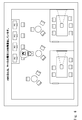
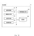
- FIG. 8 is a diagram showing an example of a processing configuration (processing module) of the server device 20 according to the first embodiment.
- the server device 20 includes a communication control unit 201, a user registration unit 202, an authentication unit 203, a user management unit 204, a search request processing unit 205, and a storage unit 206. ..
- the communication control unit 201 is a means for controlling communication with other devices. For example, the communication control unit 201 receives data (packet) from the authentication terminal 10. Further, the communication control unit 201 transmits data to the authentication terminal 10. The communication control unit 201 passes the data received from the other device to the other processing module. The communication control unit 201 transmits the data acquired from the other processing module to the other device. In this way, the other processing module transmits / receives data to / from the other device via the communication control unit 201.
- the communication control unit 201 includes a function as a receiving unit for receiving a search request and a function as a transmitting unit for transmitting an authentication result or the like.
- the user registration unit 202 is a means for realizing the above-mentioned system user registration.
- the user registration unit 202 includes a plurality of submodules.
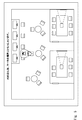
- FIG. 9 is a diagram showing an example of the processing configuration of the user registration unit 202. Referring to FIG. 9, the user registration unit 202 includes a user information acquisition unit 211, an ID generation unit 212, a feature amount generation unit 213, and an entry management unit 214.
- the user information acquisition unit 211 is a means for acquiring the user information described above.
- the user information acquisition unit 211 acquires biometric information and profiles of each of a plurality of users who use the entrance / exit management system. More specifically, the user information acquisition unit 211 acquires the biometric information (for example, face image) and profile (for example, name, affiliation, etc.) of the system user.
- the system user may input the above information into the server device 20 from his / her own terminal, or may operate the authentication terminal 10 to input the above information.
- the user information acquisition unit 211 may provide a GUI or a form for inputting the above information. For example, when the user's terminal accesses the server device 20, the user information acquisition unit 211 displays an information input form as shown in FIG. 10 on the terminal operated by the user.
- the system user inputs the information shown in FIG. After inputting all the information, the system user presses the "send” button and inputs the biometric information and the profile to the server device 20.
- the authentication terminal 10 acquires the face image of the user using the interface as shown in FIG.
- the authentication terminal 10 succeeds in acquiring the face image, the authentication terminal 10 provides the user with an interface for inputting a profile.
- the user information acquisition unit 211 stores the acquired user information in the storage unit 206.
- the ID generation unit 212 is a means for generating an ID to be assigned to a system user.
- the ID generation unit 212 When the user information input by the system user is information related to new registration, the ID generation unit 212 generates an ID for identifying the new user.
- the ID generation unit 212 may calculate the hash value of the acquired user information (face image, profile) and use the hash value as an ID to be assigned to the user.
- the ID generation unit 212 may assign a unique value to the ID each time the user is registered.
- the ID (ID for identifying the system user) generated by the ID generation unit 212 will be referred to as a “user ID”.
- the feature amount generation unit 213 is a means for generating a feature amount (feature vector composed of a plurality of feature amounts) that characterizes the face image from the face image included in the user information. Since existing techniques can be used for the feature amount generation process, detailed description thereof will be omitted. For example, the feature amount generation unit 213 extracts eyes, nose, mouth, and the like as feature points from the face image. After that, the feature amount generation unit 213 calculates the position of each feature point and the distance between the feature points as the feature amount, and generates a feature vector (vector information that characterizes the face image) composed of a plurality of feature amounts.
- the entry management unit 214 is a means for managing entries in the user information database. When registering a new user in the database, the entry management unit 214 acquires the user ID generated by the ID generation unit 212, the feature amount generated by the feature amount generation unit 213, the face image, and the user. Add an entry containing the profile you created to the user information database.
- a user information database (a database that stores a user ID that identifies a system user, biometric information, and a profile in association with each other) as shown in FIG. 12 is constructed. It should be noted that the content registered in the user information database shown in FIG. 12 is an example, and it is of course not intended to limit the information registered in the user information database.
- the authentication unit 203 is a means for performing authentication processing of a visitor who has visited the free address floor.
- the authentication unit 203 acquires an authentication request from the authentication terminal 10. Since the authentication request includes biometric information (face image) of the visitor (certified person), the authentication unit 203 retrieves the face image from the authentication request. The authentication unit 203 calculates the feature amount from the acquired face image.
- the authentication unit 203 sets the feature amount calculated based on the face image acquired from the authentication terminal 10 as the collation target, and performs the collation process with the feature amount registered in the user information database. More specifically, the authentication unit 203 sets the above-calculated feature amount (feature vector) as a collation target, and sets one-to-N (N is) with a plurality of feature vectors registered in the user information database. Positive integer, same below) Perform collation.
- the authentication unit 203 calculates the degree of similarity between the feature amount to be collated and each of the plurality of feature amounts on the registration side. For the similarity, a chi-square distance, an Euclidean distance, or the like can be used. The farther the distance is, the lower the similarity is, and the closer the distance is, the higher the similarity is.
- the authentication unit 203 If the authentication unit 203 has a plurality of feature quantities registered in the user information database whose similarity with the feature quantity to be collated is equal to or higher than a predetermined value and the feature quantity having the highest similarity degree exists. It is judged that the authentication of the verification target is successful.
- the authentication unit 203 transmits the authentication result (authentication success, authentication failure) to the authentication terminal 10 as a response to the verification request.
- the authentication unit 203 reads out the user ID corresponding to the person who succeeded in the authentication from the user information database. If the biometric authentication of the visitor is successful, the authentication unit 203 may send a response (authentication success) including the user ID of the successful authentication person (user ID of the visitor) to the authentication terminal 10. good. Further, the authentication unit 203 hands over the read user ID to the user management unit 204.
- the authentication unit 203 performs biometric authentication of the visitor using the biometric information of the visitor included in the authentication request and the biometric information of each of the plurality of users stored in the user information database.
- the authentication unit 203 transmits the result of biometric authentication to the authentication terminal 10 via the communication control unit 201.
- the user management unit 204 is a means for managing users (visitors and residents on the floor) on the free address floor.
- the user management unit 204 manages visitors by using the user ID acquired from the authentication unit 203. Specifically, the user management unit 204 manages the user ID and the position information of the person corresponding to the user ID in association with each other.
- the user management unit 204 calculates the position of the visitors in real time. As described above, the user management unit 204 calculates the position of the visitors by any means. In the first embodiment, the user management unit 204 analyzes the images obtained from the camera devices 30 arranged in various places on the free address floor and calculates the position information of the visitors. The user management unit 204 functions as a calculation unit for calculating location information regarding visitors on the free address floor.
- the user management unit 204 extracts a face area (face image) from the image data acquired from the camera device 30.
- the user management unit 204 calculates the feature amount from the extracted face image, and identifies the user ID of the person reflected in the image data by the collation process using the user information database.
- the user management unit 204 converts the coordinates of the face image in the image data (for example, the coordinates of the coordinate system whose origin is the lower left of the image data) into the coordinates on the floor (coordinates of the coordinate system whose origin is the doorway or the like). do.
- the user management unit 204 performs the above conversion using a conversion table prepared in advance and calculates the user's position information.
- the user management unit 204 updates the position information of the specified user ID with the position information calculated using the image data. Since the size of a person's face can be regarded as the same to some extent, the distance between the user and the camera device 30 can be estimated from the size of the face. Therefore, by preparing the conversion table for each size of the extracted face area, the user management unit 204 can estimate the position of the user.
- the free address floor may be divided into a grid pattern, and the camera device 30 may be assigned to each of the divided small areas.
- the user management unit 204 refers to the information (for example, table information) associated with the imaging range and the position of each camera device 30, and analyzes the image data obtained from each camera device 30 to allow the user.
- the position of may be estimated. That is, the user management unit 204 may infer the position of the person corresponding to the face image from the position of the camera device 30 that has captured the image including the face image. That is, if a person is captured in the image data obtained from the camera device 30, the user management unit 204 determines that the person is present in the imaging range of the camera device 30 and estimates the position.
- the user management unit 204 may calculate the position information of the visitors using a stereo camera or the like capable of calculating the depth direction as the camera device 30.
- the user management unit 204 analyzes the two image data and calculates the position (coordinates) and direction of the user with respect to the position of the camera device 30.
- the position information of the user is calculated by synthesizing the position of the user management unit 204 and the camera device 30 and the position of the user (adding the relative position of the user to the absolute position of the camera device 30). May be good.
- the user management unit 204 may acquire the location information from the terminal possessed by the user.
- the user's terminal may generate location information using GPS, or may generate location information based on the intensity of radio waves received from a wireless access point such as WiFi (Wireless Fidelity).
- WiFi Wireless Fidelity
- the user management unit 204 may calculate the position of the user from the address information of the PC (personal computer) used by the user. For example, the address information of the PC and the location information where the PC is installed are stored in association with each other, and the visitor is specified from the login information (information that identifies the user who uses the PC) obtained from the PC, and the location information is calculated. May be done. At the free address, by logging in to the PC placed in each table with ID and PW (PassWord) or face authentication, the location of the PC and the location of the user (user) from the logged-in ID. You may specify if you are in.
- ID and PW PassWord
- face authentication the location of the PC and the location of the user (user) from the logged-in ID. You may specify if you are in.
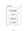
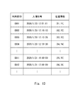
- the user management unit 204 manages the user ID, the date and time when the user entered the floor, and the location information of the user in association with each other. Specifically, the user management unit 204 manages visitors by using an attendee management database having fields for storing at least the above three pieces of information. For example, the user management unit 204 manages visitors by using the attendee management database as shown in FIG. As shown in FIG. 13, the visitor management database contains at least a user ID corresponding to a visitor in a restricted area (free address floor) where entry and exit are restricted, an entry date and time, and location information of the visitor. , Is a database that stores them in association with each other.
- the visitor management database shown in FIG. 13 is an example, and the state (working state) of the visitors may be managed in addition to the entrance date and time and location information. For example, if the attendee is in a meeting, the attendee's status is set to "meeting", and if the attendee is executing work at a round table, the attendee's status is set to "normal work”. It may be (see FIG. 14). If the place where the attendee is present is in the conference room, the state of the attendee may be set to "during the conference".
- the user management unit 204 adds a new entry to the visitor management database immediately after the user enters the free address floor. In addition, when a visitor leaves the floor, the user management unit 204 deletes the corresponding entry from the visitor management database. The user management unit 204 detects the entry / exit of the user using the image obtained from the camera device 30.
- the search request processing unit 205 is a means for processing a "search request" received from the authentication terminal 10.
- the search request processing unit 205 transmits the location information, staying time, etc. of the visitor who the visitor wishes to visit to the authentication terminal 10.
- the search request processing unit 205 follows the search request regarding the position of the visitor received from the authentication terminal 10, and the staying time (free address floor) of the visitors corresponding to the visitor among the visitors stored in the visitor management database. The length of stay in the room) is calculated.
- the search request processing unit 205 transmits the position information of the visitor, the calculated stay time, and the like to the authentication terminal 10 via the communication control unit 201.
- the search request processing unit 205 extracts information that identifies a visitor (visitor information; for example, a name) from the search request.
- the search request processing unit 205 searches the user information database using the extracted information as a search key, and identifies the corresponding user ID.
- the search request processing unit 205 refers to the visitor management database and acquires the location information (coordinate information in the floor) corresponding to the specified user ID. Further, the search request processing unit 205 determines the staying time (difference between the current time and the admission time) of the specified user based on the admission date and time (admission time) corresponding to the specified user ID and the current time. calculate.
- the search request processing unit 205 transmits the search result including the location information, the staying time, the name of the visitor who is the search target, the face image, etc. to the authentication terminal 10.
- a search request including the name (ABC) of the visitor U is transmitted to the server device 20.
- the search request processing unit 205 acquires the corresponding user ID from the user information database based on the name (ABC) included in the search request.
- the search request processing unit 205 refers to the visitor management database and acquires the position information of the person corresponding to the user ID read from the user information database.
- the search request processing unit 205 transmits the acquired position information, the calculated stay time, the name (ABC) of the search target person, and the face image to the authentication terminal 10.
- the authentication terminal 10 displays a screen showing the position of the person who wishes to visit using the acquired search results (name, face image, location information, staying time). For example, the authentication terminal 10 displays a screen as shown in FIGS. 5 and 6.
- users with the same surname and the same name may be registered in the user information database.
- the search request processing unit 205 cannot determine which of the plurality of persons with the same surname and the same name is the person who wishes to visit, so that the search results (name, face image, location information, staying time) of the plurality of persons are authenticated by the authentication terminal.
- the authentication terminal 10 may display the search results of each of the plurality of persons. In this case, the visitor may identify the person who wants to visit based on the displayed face image.
- the search request processing unit 205 transmits the name, location information, and staying time to the authentication terminal 10, and there are a plurality of corresponding persons. If it exists, the face image may be transmitted to the authentication terminal 10 in addition to the name, location information, and staying time. That is, the search request processing unit 205 may change the content to be transmitted to the authentication terminal 10 according to the acquired information of the visitor and the result obtained from the user information database.
- the search request processing unit 205 refers to the user information database and identifies the corresponding user ID from the information (for example, the name of the visitor) included in the search request. ..
- the search request processing unit 205 refers to the visitor management database and identifies the visitor corresponding to the visitor from the specified user ID.
- the storage unit 206 is a means for storing information necessary for the operation of the server device 20.
- a user information database and a visitor management database are constructed in the storage unit 206.
- the user information database is a database that stores biometric information of each of a plurality of users who can enter the restricted area, a user ID, and information that identifies each user (for example, a name) in association with each other.
- the visitor management database is a database that stores the user ID, location information, and entry date and time of the visitor in association with each other.
- the authentication terminal 10 is a terminal that manages admission to the restricted area (free address floor). When the authentication terminal 10 succeeds in authentication using the biometric information registered in the user information database, the authentication terminal 10 permits the user who succeeds in the authentication to enter the restricted area.
- FIG. 15 is a diagram showing an example of a processing configuration (processing module) of the authentication terminal 10.
- the authentication terminal 10 includes a communication control unit 301, a face image acquisition unit 302, an authentication request unit 303, a search request unit 304, a search result output unit 305, and a storage unit 306. ..
- the communication control unit 301 is a means for controlling communication with other devices. For example, the communication control unit 301 receives data (packets) from the server device 20. Further, the communication control unit 301 transmits data to the server device 20. The communication control unit 301 passes the data received from the other device to the other processing module. The communication control unit 301 transmits the data acquired from the other processing module to the other device. In this way, the other processing module transmits / receives data to / from other devices via the communication control unit 301.
- the face image acquisition unit 302 is a means for controlling a camera device (camera device included in the authentication terminal 10) and acquiring a face image (biological information) of a visitor in front of the person.
- the face image acquisition unit 302 images the front of the own device at regular or predetermined timings.
- the face image acquisition unit 302 determines whether or not the acquired image includes a human face image, and if the acquired image includes a face image, extracts the face image from the acquired image data.
- the face image acquisition unit 302 may extract a face image (face region) from the image data by using a learning model learned by CNN (Convolutional Neural Network).
- the face image acquisition unit 302 may extract the face image by using a technique such as template matching.
- the face image acquisition unit 302 delivers the extracted face image to the authentication request unit 303.
- the authentication request unit 303 is a means for requesting the server device 20 to authenticate the visitor in front of him.
- the authentication request unit 303 generates an authentication request including the acquired face image and transmits it to the server device 20.
- the authentication request unit 303 receives a response (authentication success, authentication failure) from the server device 20 to the authentication request. If the user ID is included in the response from the server device 20, the authentication request unit 303 stores the user ID in the storage unit 306.
- the authentication request unit 303 notifies the visitor to that effect. At that time, it is preferable that the authentication requesting unit 303 also notifies the contact information and the like when the authentication fails. For example, the authentication requesting unit 303 displays on the liquid crystal panel or the like that the authentication has failed and the telephone number of the contact.
- the authentication request unit 303 notifies the search request unit 304 to that effect.
- the search request unit 304 is a means for requesting the server device 20 to search for a visitor.
- the search request unit 304 displays for inputting the intention of the visitor whether or not to search for the visitor. For example, the search request unit 304 displays as shown in FIG.
- the search request unit 304 opens the gate 40 when the visitor does not want to search for the visitor (when No in FIG. 3 is selected).
- the search request unit 304 closes the gate 40 after the visitor enters the floor. Whether or not the visitor has entered the floor (whether or not the visitor has passed through the gate 40) is detected by a sensor (a sensor using infrared rays or the like) installed in the gate 40, and the detection result is detected by the authentication terminal 10. You will be notified.
- the search request unit 304 displays for inputting information about the visitor. For example, the search request unit 304 displays as shown in FIG. 4 (generates a GUI).
- the search request unit 304 generates a "search request" including information acquired via the GUI (visitor information; for example, the name of the visitor).
- the search request unit 304 transmits the generated search request to the server device 20.
- the search request unit 304 acquires a response to the above request from the server device 20.
- the search request unit 304 passes the acquired response to the search result output unit 305.
- the search result output unit 305 is a means for outputting information related to the search results acquired from the server device 20. Specifically, the search result output unit 305 outputs information regarding the position of the visitor.
- the search result output unit 305 displays, for example, a screen as shown in FIGS. 5 and 6 on the display using the response (name, face image, position information, staying time of the person who wishes to visit) acquired from the server device 20. do.
- the administrator or the like inputs information necessary for displaying the displays shown in FIGS. 5 and 6 into the authentication terminal 10 in advance. Specifically, the administrator or the like inputs information on the layout or the like and information on the coordinate system into the authentication terminal 10 in advance on the free address floor. For example, the administrator or the like stores in the authentication terminal 10 a conversion formula or the like for converting the position information (coordinate information) acquired from the server device 20 into the coordinates on the map.
- the displays shown in FIGS. 5 and 6 are examples, and are not intended to limit the output format, output form, etc. of the search result output unit 305.
- the search result output unit 305 may send the search result to the visitor's e-mail address or the like.
- the search result output unit 305 may replace the location information of the visitor with a simple expression indicating the location information and notify the visitor.
- a display or voice such as "Mr. ABC is present at the central round table" may be output.
- the search result output unit 305 may display as shown in FIG. 6 by using the staying time acquired from the server device 20.
- the storage unit 306 is a means for storing information necessary for the operation of the authentication terminal 10.
- FIG. 16 is a sequence diagram showing an example of the operation of the entrance / exit management system according to the first embodiment. Note that FIG. 16 is a sequence diagram showing an example of system operation when a visitor wishes to search for a visitor. Prior to the operation shown in FIG. 16, it is assumed that the system user has been registered in advance.
- the authentication terminal 10 When the visitor is located in front of the authentication terminal 10, the authentication terminal 10 acquires the face image of the visitor. The authentication terminal 10 transmits an authentication request including a face image to the server device 20 (step S01).
- the server device 20 executes an authentication process (a collation process using a feature amount registered in the user information database) using the acquired face image (step S11).
- the server device 20 transmits the result of the authentication process (authentication success, authentication failure) to the authentication terminal 10.
- the authentication terminal 10 transmits a search request including the name of the visitor to the server device 20 (step S02).
- the server device 20 extracts information on the person who wants to visit from the search request, and specifies the location information of the person who wants to visit using the user information database and the visitor management database (step S12).
- the server device 20 transmits a response (response to a search request) including location information, stay time, etc. to the authentication terminal 10 (step S13).
- the authentication terminal 10 outputs information that clearly indicates the location of the visitor using the acquired location information, staying time, etc. (outputs the location information of the visitor; step S03).
- the server device 20 refers to the visitor management database and the like to acquire the location information of the person whom the visitor wishes to visit. Further, the server device 20 calculates the staying time of the visitor. The server device 20 transmits the location information and the staying time of the visitor to the authentication terminal 10. The authentication terminal 10 displays so that the visitor can grasp the position and staying time of the visitor. As a result, the visitor can easily determine whether or not to visit the visitor in consideration of the staying time while grasping the position of the person who wishes to visit.
- the configuration of the entrance / exit management system according to the second embodiment can be the same as that of the first embodiment, the description corresponding to FIG. 2 will be omitted. Further, since the processing configuration of the authentication terminal 10 and the server device 20 according to the second embodiment can be the same as that of the first embodiment, the description thereof will be omitted. Hereinafter, the differences between the first and second embodiments will be mainly described.
- the user registration unit 202 of the server device 20 acquires information on a person frequently visited by the user when registering the system user. More specifically, the user information acquisition unit 211 generates a GUI as shown in FIG. A user who comes into contact with the GUI presses the "Registration" button provided at the lower right when he / she wishes to register a person who visits frequently.
- the user information acquisition unit 211 In response to pressing the button, the user information acquisition unit 211 generates a GUI as shown in FIG. According to the GUI, the user registers a person who frequently visits. For example, the system user inputs the names of persons in charge of other departments with which they are collaborating. Alternatively, the user information acquisition unit 211 refers to a digitized employee list, etc., displays candidates for registrants when the user inputs all or part of the name, and among the candidates displayed by the user. You may generate a GUI that selects a registrant from. Alternatively, the user information acquisition unit 211 may specify the registrant by an employee number or the like instead of the name (the employee number may be input).
- the user information acquisition unit 211 acquires information (name of candidate, etc.) about a person (candidate) who is a candidate for a visitor of each user registered in the user information database.
- the user information acquisition unit 211 stores the acquired candidate information together with the system user's biological information (face image, feature amount) and attribute information (name, affiliation, etc.) in the user information database (see FIG. 19). ..
- the user information database includes biometric information, a user ID, information that identifies each user (user's name, etc.), and a request for each user to visit. Memorize at least one candidate (such as the candidate's name) for a person.
- the search request unit 304 of the authentication terminal 10 grasps that the visitor requests the search of the visitor by the GUI as shown in FIG. 20, it transmits a "search request" to the server device 20. At that time, the search request unit 304 transmits a search request including the user ID of the visitor (successful authentication person) to the server device 20. In the second embodiment, the search request transmitted from the authentication terminal 10 does not include the name of the person who wishes to visit.
- the search request processing unit 205 of the server device 20 acquires the user ID from the received search request.
- the search request processing unit 205 searches the user information database using the acquired user ID as a key, and identifies an entry corresponding to the visitor.
- the search request processing unit 205 refers to the candidate field of the specified entry and acquires the candidate information (name, employee number, etc.). In the example of FIG. 19, if the user ID is "ID01", the names (AA1, AA2) of the two candidates are acquired.
- the search request processing unit 205 searches the user information database using the acquired candidate's name as a key, and acquires the corresponding user ID.
- “ID11” is specified as the user ID of the user having the name of "AA1”
- “ID12” is specified as the user ID of the user having the name of "AA2”.
- the search request processing unit 205 searches the admission management database using the specified user ID as a key, and identifies the corresponding entry. With reference to FIG. 13, in the above example, the entries on the 6th and 7th lines are specified.
- the search request processing unit 205 generates a search result to be transmitted to the authentication terminal 10 based on the information of the specified entry.
- the search request processing unit 205 transmits the search result including the location information, the staying time, the name (name of the candidate), and the face image to the authentication terminal 10 for each of the two registrants.
- the search request processing unit 205 transmits a search result including that fact to the authentication terminal 10. Specifically, the search result including the name, face image, etc. of the absent candidate (pre-registered visitor) is transmitted to the authentication terminal 10. When the visitor's visitor is absent on the free address floor, the search request processing unit 205 notifies the authentication terminal 10 that the visitor is absent.
- the search request unit 304 of the authentication terminal 10 passes the response (search result) acquired from the server device 20 to the search result output unit 305.
- the search result output unit 305 displays, for example, a screen as shown in FIG. 21 on the display using the response (candidate's name, face image, position information, staying time, etc.) acquired from the server device 20.
- the response candidate's name, face image, position information, staying time, etc.
- the color of the marker is changed according to the staying time of the candidate (visitor).
- the search result output unit 305 displays as shown in FIG. 22 and clearly indicates the absentee.
- the authentication terminal 10 indicates that the visitor is absent.
- the server device 20 refers to the user information database and identifies the candidate from the user ID of the visitor included in the search request.
- the server device 20 calculates the staying time of the visitors corresponding to the candidates among the visitors stored in the visitor management database, and transmits the stay time to the authentication terminal 10 together with the location information and the like. That is, in the second embodiment, the visitor does not need to input the name and the like of the visitor, and can know the position and staying time of the visitor with a simple operation.
- the combination of the first and second embodiments will be described.
- the case of combining the form) will be described.
- the configuration of the entrance / exit management system according to the third embodiment can be the same as that of the first and second embodiments, the description corresponding to FIG. 2 will be omitted. Further, since the processing configuration of the authentication terminal 10 and the server device 20 according to the third embodiment can be the same as those of the first and third embodiments, the description thereof will be omitted. Hereinafter, the differences between the first to third embodiments will be mainly described.
- the search request unit 304 of the authentication terminal 10 according to the third embodiment acquires the search method desired by the visitor by the GUI as shown in FIG. 23.
- the operation of the entrance / exit management system according to the third embodiment can be the same as the operation of the entrance / exit management system according to the second embodiment. Therefore, the explanation is omitted.
- the search request unit 304 searches for information that identifies the visitor (visitor information; name, etc.) and a user ID of the successful authentication person (visitor). The request is transmitted to the server device 20.
- the search request processing unit 205 processes the request in the same manner as in the first embodiment. Further, the search request processing unit 205 searches the user information database using the user ID of the visitor included in the search request as a key, and identifies the corresponding entry. The search request processing unit 205 stores visitor information (name of a person who is requested to visit, etc.) included in the search request in the candidate field of the specified entry. That is, the search request processing unit 205 treats the user to whom the visitor has instructed the search as the "pre-registered person" described in the second embodiment, and registers the user in the user information database.
- the search request processing unit 205 When it is requested to search the position of the pre-registered user (candidate for visitor), the search request processing unit 205 is pre-registered by using the above user information database as a search target. It enables a position search that includes not only a person but also a person specified by a past position search.
- the server device 20 when the search request includes the information for identifying the visitor and the user ID of the visitor, the server device 20 according to the third embodiment informs the visitor of the user information database.
- the information that identifies the prospective visitor is stored in the corresponding entry as candidate information.
- the candidates stored in the user information database are strengthened, and the convenience of the user can be improved.
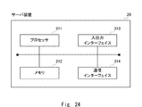
- FIG. 24 is a diagram showing an example of the hardware configuration of the server device 20.
- the server device 20 can be configured by an information processing device (so-called computer), and includes the configuration illustrated in FIG. 24.
- the server device 20 includes a processor 311, a memory 312, an input / output interface 313, a communication interface 314, and the like.
- the components such as the processor 311 are connected by an internal bus or the like and are configured to enable mutual communication.
- the configuration shown in FIG. 24 does not mean to limit the hardware configuration of the server device 20.
- the server device 20 may include hardware (not shown) or may not include an input / output interface 313 if necessary.
- the number of processors 311 and the like included in the server device 20 is not limited to the example shown in FIG. 24, and for example, a plurality of processors 311 may be included in the server device 20.
- the processor 311 is a programmable device such as a CPU (Central Processing Unit), an MPU (Micro Processing Unit), and a DSP (Digital Signal Processor). Alternatively, the processor 311 may be a device such as an FPGA (Field Programmable Gate Array) or an ASIC (Application Specific Integrated Circuit). The processor 311 executes various programs including an operating system (OS).
- OS operating system
- the memory 312 is a RAM (RandomAccessMemory), a ROM (ReadOnlyMemory), an HDD (HardDiskDrive), an SSD (SolidStateDrive), or the like.
- the memory 312 stores an OS program, an application program, and various data.
- the input / output interface 313 is an interface of a display device or an input device (not shown).
- the display device is, for example, a liquid crystal display or the like.
- the input device is, for example, a device that accepts user operations such as a keyboard and a mouse.
- the communication interface 314 is a circuit, module, etc. that communicates with other devices.
- the communication interface 314 includes a NIC (Network Interface Card) and the like.
- the function of the server device 20 is realized by various processing modules.
- the processing module is realized, for example, by the processor 311 executing a program stored in the memory 312.
- the program can also be recorded on a computer-readable storage medium.
- the storage medium may be a non-transient such as a semiconductor memory, a hard disk, a magnetic recording medium, or an optical recording medium. That is, the present invention can also be embodied as a computer program product. Further, the above program can be downloaded via a network or updated by using a storage medium in which the program is stored. Further, the processing module may be realized by a semiconductor chip.
- the authentication terminal 10 can also be configured by an information processing device like the server device 20, and its basic hardware configuration is not different from that of the server device 20, so the description thereof will be omitted.
- the authentication terminal 10 may be provided with a camera device, a liquid crystal display, or the like.
- the server device 20 is equipped with a computer, and the function of the server device 20 can be realized by causing the computer to execute a program. Further, the server device 20 executes the control method of the server device 20 by the program.
- the name and face image of the visitor are transmitted from the server device 20 to the authentication terminal 10.
- other information may be transmitted to the authentication terminal 10.
- the status of the visitor for example, during normal work or during a meeting
- the authentication terminal 10 also displays the status of the visitor, and provides a material for determining whether or not the visitor really visits the visitor.
- the server device 20 may be linked with another server or database that manages information about the visitors on the floor. For example, the server device 20 transmits the name and employee number of the visitor to the other server or the like, and acquires the schedule information of the visitor. The server device 20 may also transmit the acquired schedule information to the authentication terminal 10. With such a response, if the authentication terminal 10 and the visitor are absent, it is possible to display the return time and the place of stay of the absentee.
- the authentication terminal 10 when the location information of a plurality of visitor (including absentees) is displayed, the authentication terminal 10 is the visitor selected by the visitor. You may display the schedule information of. For example, in the example of FIG. 21, when the visitor wants to know the schedule of the visitor AA1, the corresponding schedule information is displayed by clicking the marker of the visitor. Through such a response, the visitor can know the schedule of the visitor and can make an appropriate decision as to whether or not to visit the visitor. For example, if a person who wishes to visit is immediately absent from the meeting, the visitor will refrain from visiting the person who wishes to visit.
- the server device 20 may manage the floor by dividing it into small pieces and calculate the staying time in a small area.
- the server device 20 may calculate the staying time of the small area of the destination. That is, the server device 20 may calculate the time spent in substantially the same place in the restricted area (free address floor) as the staying time of each visitor.
- the profile of the system user may be input using a scanner or the like.
- the user inputs an image related to his / her business card into the server device 20 using a scanner.
- the server device 20 executes optical character recognition (OCR; Optical Character Recognition) processing on the acquired image.
- OCR optical character recognition
- the server device 20 may determine the profile of the user based on the obtained information.
- the biometric information related to the "face image” is transmitted from the authentication terminal 10 to the server device 20 has been described.
- the biometric information related to the "feature amount generated from the face image” may be transmitted from the authentication terminal 10 or the like to the server device 20.
- the server device 20 may execute a collation process with the feature amount registered in the user information database using the acquired feature amount (feature vector).
- the server device 20 may notify the visitor of the visitor's visit. Specifically, when the server device 20 acquires a search request including the name of the visitor from the visitor via the authentication terminal 10, the server device 20 notifies the visitor of the existence of the visitor. You may send an email to do so.
- the authentication terminal 10 controls admission to the free address floor.
- the use of the authentication terminal 10 is not limited to controlling admission to the free address floor.
- the authentication terminal 10 may be used for restricting admission to an event venue, an exhibition, or the like.
- the authentication terminal 10 may be a terminal that performs two-factor authentication when entering the floor, or may be a terminal that makes a payment by face authentication (for example, a face authentication self-registration).
- each embodiment may be used alone or in combination. For example, it is possible to replace a part of the configuration of the embodiment with the configuration of another embodiment, or to add the configuration of another embodiment to the configuration of the embodiment. Further, it is possible to add, delete, or replace a part of the configuration of the embodiment with another configuration.
- the present invention is suitably applicable to an entrance / exit management system or the like performed on a free address floor of a company or the like.
- [Appendix 1] A visitor management database that stores the location information and entry date and time of visitors in the restricted area, A receiving unit that receives a search request for a visitor who the visitor wishes to visit from an authentication terminal that controls the visitor's entry into the restricted area.
- a search request processing unit that calculates the staying time of the visitors corresponding to the visitor among the visitors stored in the visitor management database according to the search request.
- a transmission unit that transmits the location information of the visitor and the calculated stay time to the authentication terminal.
- a server device Further equipped with a user information database that stores biometric information of each of a plurality of users who can enter the restricted area, user IDs, and information identifying each user in association with each other.
- the visitor management database stores the user ID, location information, and entry date and time of the visitor in association with each other.
- the search request contains information that identifies the visitor.
- the search request processing unit refers to the user information database and identifies the corresponding user ID from the information for identifying the visitor included in the search request, and at the same time, identifies the corresponding user ID.
- the server device according to Appendix 1, which identifies a visitor corresponding to the visitor from the specified user ID with reference to the visitor management database. [Appendix 3]
- the receiving unit receives an authentication request including the biometric information of the visitor from the authentication terminal, and receives the authentication request.
- an authentication unit that performs biometric authentication of the visitor using the biometric information included in the authentication request and the biometric information stored in the user information database.
- the server device according to Appendix 2 wherein the transmission unit transmits the result of the biometric authentication to the authentication terminal.
- the server device according to Appendix 3 The server device according to Appendix 3, wherein the transmission unit transmits an authentication result including the user ID of the visitor to the authentication terminal when the biometric authentication of the visitor is successful.
- the user information database stores at least one candidate for each user's visitor, in addition to the biometric information, the user ID, and the information that identifies each user.
- the receiving unit receives the search request that does not include the information that identifies the visitor and includes the user ID of the visitor.
- the search request processing unit refers to the user information database, identifies the candidate from the user ID of the visitor included in the search request, and is a visitor stored in the visitor management database.
- the server device according to Appendix 4 which calculates the staying time of a visitor corresponding to the candidate.
- the search request processing unit makes the visit in the entry corresponding to the visitor in the user information database.
- the server device according to Appendix 5 which stores information that identifies a desired person as information on the candidate.
- An authentication terminal that controls the entrance of visitors to the restricted area
- the server device connected to the authentication terminal and Including
- the server device is A visitor management database that stores the location information and entry date and time of visitors in the restricted area,
- a receiving unit that receives a search request for a visitor who the visitor wishes to visit from the authentication terminal.
- a search request processing unit that calculates the staying time of the visitors corresponding to the visitor among the visitors stored in the visitor management database according to the search request.
- a transmission unit that transmits the location information of the visitor and the calculated stay time to the authentication terminal.
- the staying time of the visitors corresponding to the visitor among the visitors stored in the visitor management database is calculated.
- Appendix 14 A computer installed in a server device equipped with a visitor management database that stores the location information of visitors in the restricted area and the date and time of entry.
Abstract
L'invention concerne un dispositif serveur capable de déterminer facilement si des visiteurs doivent rencontrer une personne tout en saisissant la position de la personne que les visiteurs souhaitent rencontrer. Le dispositif serveur (20) comprend une base de données de gestion d'admission de personnes (101), une unité de réception (102), une unité de traitement de demande de recherche (103) et une unité de transmission (104). La base de données de gestion d'admission de personnes (101) stocke des informations d'emplacement et la date et l'heure d'admission de la personne admise dans une zone à accès limité. L'unité de réception (102) reçoit une demande de recherche de personnes qui souhaitent se rencontrer, parmi les visiteurs, à partir d'un terminal d'authentification (10) qui commande l'admission du visiteur dans la zone à accès limité. L'unité de traitement de demande de recherche (103), en réponse à la demande de recherche, calcule le temps de séjour de personnes admises correspondant aux personnes qui souhaitent se rencontrer, parmi les personnes admises stockées dans la base de données de gestion d'admission de personnes (101). L'unité de transmission (104) transmet les informations de position et le temps de séjour calculé des personnes qui souhaitent se rencontrer au terminal d'authentification (10).
Priority Applications (2)
| Application Number | Priority Date | Filing Date | Title |
|---|---|---|---|
| PCT/JP2020/026835 WO2022009380A1 (fr) | 2020-07-09 | 2020-07-09 | Dispositif serveur, système de gestion d'entrée/sortie, procédé de commande de dispositif serveur et support d'enregistrement |
| JP2022534588A JPWO2022009380A5 (ja) | 2020-07-09 | サーバ装置、入退場管理システム、サーバ装置の制御方法及びプログラム |
Applications Claiming Priority (1)
| Application Number | Priority Date | Filing Date | Title |
|---|---|---|---|
| PCT/JP2020/026835 WO2022009380A1 (fr) | 2020-07-09 | 2020-07-09 | Dispositif serveur, système de gestion d'entrée/sortie, procédé de commande de dispositif serveur et support d'enregistrement |
Publications (1)
| Publication Number | Publication Date |
|---|---|
| WO2022009380A1 true WO2022009380A1 (fr) | 2022-01-13 |
Family
ID=79552478
Family Applications (1)
| Application Number | Title | Priority Date | Filing Date |
|---|---|---|---|
| PCT/JP2020/026835 WO2022009380A1 (fr) | 2020-07-09 | 2020-07-09 | Dispositif serveur, système de gestion d'entrée/sortie, procédé de commande de dispositif serveur et support d'enregistrement |
Country Status (1)
| Country | Link |
|---|---|
| WO (1) | WO2022009380A1 (fr) |
Citations (8)
| Publication number | Priority date | Publication date | Assignee | Title |
|---|---|---|---|---|
| JP2003044892A (ja) * | 2001-07-27 | 2003-02-14 | Matsushita Electric Ind Co Ltd | 来訪者管理装置 |
| JP2003208493A (ja) * | 2002-01-11 | 2003-07-25 | Fujitsu Ltd | 企業エントランスにおける自動受付に関する方法 |
| JP2010140211A (ja) * | 2008-12-11 | 2010-06-24 | Hitachi Ltd | 在席管理システム |
| JP2011076332A (ja) * | 2009-09-30 | 2011-04-14 | Brother Industries Ltd | 情報処理装置、情報処理システム、サーバ、応対端末、情報処理方法及び情報処理プログラム |
| JP2017182334A (ja) * | 2016-03-29 | 2017-10-05 | 本田技研工業株式会社 | 受付システム及び受付方法 |
| JP2019101566A (ja) * | 2017-11-29 | 2019-06-24 | 株式会社 プロネット | 情報処理システム、情報処理方法、情報処理プログラム、および情報処理装置 |
| WO2019163542A1 (fr) * | 2018-02-22 | 2019-08-29 | パナソニックIpマネジメント株式会社 | Système d'affichage d'état de présence et procédé d'affichage d'état de présence |
| JP2020038552A (ja) * | 2018-09-05 | 2020-03-12 | 株式会社日立情報通信エンジニアリング | フリーアドレスオフィス管理システムおよび入退管理システム |
-
2020
- 2020-07-09 WO PCT/JP2020/026835 patent/WO2022009380A1/fr active Application Filing
Patent Citations (8)
| Publication number | Priority date | Publication date | Assignee | Title |
|---|---|---|---|---|
| JP2003044892A (ja) * | 2001-07-27 | 2003-02-14 | Matsushita Electric Ind Co Ltd | 来訪者管理装置 |
| JP2003208493A (ja) * | 2002-01-11 | 2003-07-25 | Fujitsu Ltd | 企業エントランスにおける自動受付に関する方法 |
| JP2010140211A (ja) * | 2008-12-11 | 2010-06-24 | Hitachi Ltd | 在席管理システム |
| JP2011076332A (ja) * | 2009-09-30 | 2011-04-14 | Brother Industries Ltd | 情報処理装置、情報処理システム、サーバ、応対端末、情報処理方法及び情報処理プログラム |
| JP2017182334A (ja) * | 2016-03-29 | 2017-10-05 | 本田技研工業株式会社 | 受付システム及び受付方法 |
| JP2019101566A (ja) * | 2017-11-29 | 2019-06-24 | 株式会社 プロネット | 情報処理システム、情報処理方法、情報処理プログラム、および情報処理装置 |
| WO2019163542A1 (fr) * | 2018-02-22 | 2019-08-29 | パナソニックIpマネジメント株式会社 | Système d'affichage d'état de présence et procédé d'affichage d'état de présence |
| JP2020038552A (ja) * | 2018-09-05 | 2020-03-12 | 株式会社日立情報通信エンジニアリング | フリーアドレスオフィス管理システムおよび入退管理システム |
Also Published As
| Publication number | Publication date |
|---|---|
| JPWO2022009380A1 (fr) | 2022-01-13 |
Similar Documents
| Publication | Publication Date | Title |
|---|---|---|
| JP6246403B1 (ja) | 入場管理システム | |
| CN111628870B (zh) | 用于电子钥匙供应、用户验证和访问管理的系统和方法 | |
| US20220027863A1 (en) | Systems and methods for mobile application requests of physical facilities | |
| JP6943087B2 (ja) | 認証システム、認証制御装置、認証制御装置の制御方法、およびプログラム | |
| US20190080197A1 (en) | Communication terminal, communication system, and image processing method | |
| JP2014518573A (ja) | 空間的および時間的近接性に基づく顔認識 | |
| US11245707B2 (en) | Communication terminal, communication system, communication control method, and recording medium | |
| JP2005103722A (ja) | 協調ロボット装置、システム、およびナビゲーションロボット装置 | |
| US20210383099A1 (en) | Thermal sensing and identity authentication system and method | |
| CN112805722A (zh) | 减少面部识别中的误报的方法和装置 | |
| US20220019472A1 (en) | Method of storing electronic data, resource reservation system, and terminal apparatus | |
| WO2022003766A1 (fr) | Dispositif de traitement d'informations, système favorisant l'authentification de visage, procédés de traitement d'informations et support lisible par ordinateur non transitoire dans lequel un programme est stocké | |
| JP7439897B2 (ja) | 滞在管理装置、滞在管理方法、プログラム及び滞在管理システム | |
| WO2022009380A1 (fr) | Dispositif serveur, système de gestion d'entrée/sortie, procédé de commande de dispositif serveur et support d'enregistrement | |
| US20230056154A1 (en) | Server device, conference room management method, and program recording medium | |
| US11134079B2 (en) | Cognitive behavioral and environmental access | |
| JP2018120375A (ja) | システム及び方法 | |
| JP2021026639A (ja) | 利用者認証システム | |
| WO2021171607A1 (fr) | Terminal d'authentification, système de gestion d'entrée/sortie, procédé de gestion d'entrée/sortie, et programme | |
| WO2021171614A1 (fr) | Dispositif serveur, système de gestion d'entrée/sortie, et procédé et programme de gestion d'entrée/sortie | |
| JP2017170755A (ja) | サービス提供システム、移動型機器、サーバ機器、およびサービス提供プログラム | |
| JP7047297B2 (ja) | 情報処理装置及びプログラム | |
| WO2020213170A1 (fr) | Dispositif d'affichage d'informations et système d'affichage de plan d'activité | |
| JP2019159423A (ja) | 情報処理装置、データ表示方法、プログラム、通信システム、通信方法、登録情報管理装置 | |
| WO2024003985A1 (fr) | Dispositif serveur, système, procédé de commande de dispositif serveur et support de stockage |
Legal Events
| Date | Code | Title | Description |
|---|---|---|---|
| 121 | Ep: the epo has been informed by wipo that ep was designated in this application |
Ref document number: 20944478 Country of ref document: EP Kind code of ref document: A1 |
|
| ENP | Entry into the national phase |
Ref document number: 2022534588 Country of ref document: JP Kind code of ref document: A |
|
| NENP | Non-entry into the national phase |
Ref country code: DE |
|
| 122 | Ep: pct application non-entry in european phase |
Ref document number: 20944478 Country of ref document: EP Kind code of ref document: A1 |