WO2022009266A1 - Paravent de balance - Google Patents
Paravent de balance Download PDFInfo
- Publication number
- WO2022009266A1 WO2022009266A1 PCT/JP2020/026409 JP2020026409W WO2022009266A1 WO 2022009266 A1 WO2022009266 A1 WO 2022009266A1 JP 2020026409 W JP2020026409 W JP 2020026409W WO 2022009266 A1 WO2022009266 A1 WO 2022009266A1
- Authority
- WO
- WIPO (PCT)
- Prior art keywords
- windshield
- wind screen
- weighing
- opening
- weighing pan
- Prior art date
Links
Images


Classifications
-
- G—PHYSICS
- G01—MEASURING; TESTING
- G01G—WEIGHING
- G01G21/00—Details of weighing apparatus
- G01G21/28—Frames, Housings
- G01G21/286—Frames, Housings with windshields
-
- G—PHYSICS
- G01—MEASURING; TESTING
- G01G—WEIGHING
- G01G21/00—Details of weighing apparatus
- G01G21/22—Weigh pans or other weighing receptacles; Weighing platforms
Definitions
- the present invention relates to a windshield used for a balance, particularly a high resolution balance.
- the balance has a load-bearing part centered on the weighing pan, such as the flow of air around the weighing pan, such as the wind of an air conditioner, the breath of a person during weighing, and the air flow generated when a person walks.
- a windshield is provided to prevent it from acting as a wind pressure and adversely affecting the measurement.
- the windshield is provided with an opening / closing door for placing the sample to be weighed on the weighing pan, and an air flow is generated when the opening / closing door is opened / closed. After the opening / closing door is closed, this air flow is attenuated while moving in the windshield, but if it hits the weighing pan during this movement process, it will adversely affect the weighing. This adverse effect is particularly large in a balance having a high resolution, for example, a balance having a resolution of about 1/10 million.
- a configuration in which a windshield that further covers the weighing pan is conventionally known in the windshield.
- it has a bottom that has an opening on the side wall inside the outer windshield that is cylindrical with a ceiling and has an opening on the side wall, and the bottom plate located below this opening is rotatably supported by three pieces.
- Patent Document 1 a balance in which a cylindrical inner windshield is provided and a weighing pan is arranged inside the inner windshield.
- the inner windshield rotates in a non-contact state with respect to the outer windshield, and the windshield is in the open state when the openings of both are aligned, and the windshield is in the closed state when the openings do not match. Since the inner windshield rotates with the bottom plate supported by the top, the dust generated during this rotation falls due to its own weight because the position of the top is located below the opening of the inner windshield. It does not flow in the direction of the weighing pan. If there is a downflow that flows from above to below, the air that has flowed in from the opening of the outer windshield flows downward through the gap between the outer windshield and the inner windshield so as to pass through the coma, and flows in the direction of the weighing pan. There is no such thing.
- the inner windshield merely functions as a shutter for opening and closing the opening of the outer windshield, and cannot prevent the inflow of air flowing laterally into the inner windshield. There is an inconvenience that the air hits the surface and the adverse effect of the air flow during weighing cannot be avoided.
- An object of the present invention is to provide a windshield for a balance that eliminates this inconvenience.
- the windshield for a balance includes an outer windshield forming a weighing chamber and an inner windshield arranged inside the outer windshield and covering the weighing pan, and the outer windshield is provided with the outer windshield.
- the inner windshield has a slide door that can be opened and closed on the side surface, and the surface facing the slide door is opened, and a shielding wall is provided below the opening.
- the air flowing in from the opening formed by opening the slide door of the outer windshield flows into the inner windshield along the floor surface of the outer windshield. It moves toward, but is blocked by the shielding wall and does not flow into the inner windshield.
- the sample can be placed on the weighing pan for weighing and the sample can be taken out after weighing through the opening formed in the outer windshield and the opening of the inner windshield.
- the upper end of the shielding wall is set at a position approximately the same as the height of the weighing pan, the inflow of air into the inner windshield is surely blocked, and the sample is placed on the weighing pan. It is possible to secure a sufficient width of the opening required for the removal work.
- the slide doors are provided on each pair of side surfaces of the outer windshield, and the inner windshield can be detachably or rotatably provided so that the opening of the inner windshield faces one of the desired slide doors. Once configured, the sample can be placed and taken out from the desired side direction of the outer windshield.
- the outer windshield and the inner windshield are provided to form a double structure of the windshield, and a shielding wall is provided below the opening of the inner windshield to allow air to flow to the weighing pan provided in the inner windshield.
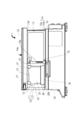
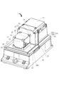
- the perspective view which shows one Embodiment of the balance which concerns on this invention is omitted not shown in the outside windshield.
- Side view showing the state where the slide door of the outer windshield is opened.
- Front view showing the height relationship between the shielding wall and the weighing pan by omitting a part of the outer windshield and the inner windshield.
- the balance 1 has a housing 50 in which a mass sensor (not shown) such as an electromagnetic equilibrium type or a load cell type is housed, and a weighing pan in which a sample is placed in connection with the mass sensor. It has 51 and. Further, an annular wall 52 is provided so as to surround the weighing pan 51.
- a windshield 10 is provided on the upper surface of the housing 50.
- the windshield 10 includes an outer windshield 11 forming a weighing chamber S and an inner windshield 21 arranged inside the outer windshield 11 and covering the weighing pan 51.
- the windshield 10 is a load-bearing portion centered on the weighing pan 51, such as the flow of air around the weighing chamber S, such as the wind of an air conditioner, the breath of a person during weighing, and the flow of air generated when a person walks. It acts as a wind pressure to prevent the measurement from being affected.
- the outer windshield 11 forms a front plate 12, a pair of left and right slide doors 13 and 13 that open and close the side surfaces, a top door 14 that opens and closes the upper surface, and a back plate that forms one surface of a box-shaped case 15 that closes the back surface. 16 to form a nearly rectangular parallelepiped weighing chamber S. It is desirable that the front plate 12, the pair of slide doors 13, 13 and the upper surface door 14 are made of glass or resin and are transparent so that the internal state can be observed. Further, in order to prevent the generation of static electricity, it is desirable that the glass is a conductive glass having a conductive film on the surface and the resin is a conductive resin having conductivity.
- the outer windshield 11 may be detachably provided on the housing 50 by a known detachable mechanism, or may be fixed so as not to be detachable.
- the slide door 13 has a square outer frame 13a, and the upper portion of the outer frame 13a includes an upper frame 31 and a cylinder box 32 provided along one side of the upper surface door 14. It is slidably supported and suspended.
- the slide door 13 is configured to reciprocate by the driving force of an air cylinder (not shown) arranged in the cylinder box 32. This reciprocating motion is performed by being guided by a guide rail 34 having an L-shaped cross section formed by the horizontal portion 33a and the rising portion 33b of the lower frame 33 at the lower portion of the outer frame 13a.
- the lower end of the outer frame 13a of the slide door 13 is in a non-contact state separated from the horizontal portion 33a of the lower frame 33.
- the slide door 13 can be reciprocated by the driving force of the air cylinder and can also be reciprocated manually.
- a handle 13b is provided on the front plate 12 side.
- the upper door 14 is configured to be reciprocating in the front-rear direction along a guide groove (not shown) provided in the cylinder boxes 32 and 32.
- the upper door 14 is provided with a handle 14a on the case 15 side for manual movement.
- the lower ends of the slide doors 13 and 13 are located on the lower frame 33 at positions along the movement paths of the slide doors 13 and 13.
- Each of the slide doors 13 and 13 is provided with regulating protrusions 35 and 35 that regulate the rising portion 33b, that is, the vertical portion of the guide rail 34 so as not to be displaced in the direction of separation.
- the shapes of the regulating protrusions 35 and 35 are octagonal columns, although they are not clear in the figure.
- the regulation protrusions 35, 35 are located on the side surface thereof so that they can always come into contact with the lower end portions of the corresponding slide doors 13, 13 regardless of whether the slide doors 13, 13 are in the closed state or the open state. It is in.
- the regulating protrusions 35 and 35 prevent the lower portions of the slide doors 13 and 13 in a non-contact state with the horizontal portion 33a of the guide rail 34 from fluttering, and ensure smooth movement of the slide doors 13 and 13. Further, since the regulation protrusions 35, 35 are always in contact with the lower end portions of the corresponding slide doors 13, 13, the fluttering prevention is ensured in the entire range of movement of the slide doors 13, 13. ..
- the shape of each of the regulation protrusions 35, 35 may be another polygonal column or a cylinder.
- the inner windshield 21 has a front plate 22, a top plate 23, a side plate 24, a back plate 25, and an opening 26 in which one of the side surfaces is open.
- the upper end corners of the front plate 22, the side plate 24, and the back plate 25 are connected and fixed to the four corners of the top plate 23 by resin fixtures 27, 27, 27, 27.
- the lower end corners of the front plate 22, the side plate 24, and the back plate 25 are made of resin and fixed by a rectangular fixing frame 28. Then, the inner windshield 21 forms a rectangular parallelepiped shape with one side open.
- the inner windshield 21 is arranged on the upper surface plate 36 of the lower frame 33 by a fixed frame 28 so that the opening 26 faces the slide door 13 on the right side surface so as to cover the weighing pan 51, and a known attachment / detachment mechanism ( It is detachably attached by (not shown). Therefore, the inner windshield 21 can be arranged so that the opening 26 faces the other slide door 13 (see FIG. 2).
- a portion corresponding to the lower portion of the opening 26 of the fixed frame 28 constitutes the shielding wall 28a.
- the height position of the upper end of the shielding wall 28a is substantially the same as the height position of the weighing pan 51.
- the height position of the upper end of the shielding wall 28a is the same as or slightly higher than the height position of the weighing pan 51, which makes it more reliable to prevent the inflow of air into the inner windshield 21.
- the inflow blocking function can be maintained although the certainty is lowered.
- a shallow boat-shaped container made of aluminum foil, ceramic, platinum, etc. which is mainly called a boat containing liquid or powder samples for elemental analysis, is pinched with tweezers and moved horizontally. Then, when the sample is placed on the weighing pan 51 without spilling, the shielding wall 28a does not get in the way and the work can be easily and surely performed.
- the front plate 22, the top plate 23, the side plate 24, and the back plate 25 of the inner windshield 21 are made of glass or resin and are transparent so that the internal state can be observed. Further, in order to prevent the generation of static electricity, it is desirable that the glass is a conductive glass having a conductive film on the surface and the resin is a conductive resin having conductivity.
- the slide door 13 on the right side of the outer windshield 11 is opened, and from the opened side surface, through the opening 26 of the inner windshield 21, onto the weighing pan 51. After placing the sample, the slide door 13 is closed and the weighing chamber S is closed. At the time of this weighing, the weighing chamber S is in a closed state and is not affected by the outside.
- the inner windshield 21 is temporarily removed from the upper surface plate 36, and the inner windshield 21 is attached to the upper surface plate 36 so that the directions of the openings 26 are opposite to each other. Then, the slide door 13 on the left side surface of the outer windshield 10 is opened, the sample is placed on the weighing pan 51 from the opened side surface through the opening 26 of the inner windshield 21, and then the slide door 13 is closed. Weighing can be performed with the weighing chamber S closed.
- the outer windshield 11 and the inner windshield 21 are not limited to a rectangular parallelepiped shape, and may both have a cylindrical shape with an upper surface closed.
- the outer windshield 11 may have a rectangular parallelepiped shape
- the inner windshield 21 may have a planar U-shaped box body.
- the inner windshield 21 of this planar U-shaped box is suitable because it can sufficiently secure an opening as compared with the cylindrical shape, as in the rectangular parallelepiped shape.
- the opening 26 of the inner windshield 21 can be made to face the slide door 13 on the desired side of the outer windshield 11 by rotating the inner windshield in a predetermined direction. This rotatable configuration can be realized using conventionally known means.
- the annular wall 52 also has a function of blocking the air flow and the accompanying dust from reaching the weighing pan 51.
- the shielding wall 28a blocks the inflow of air into the inner windshield 21.
- the annular wall 52 does not necessarily have to be provided.
Landscapes
- Physics & Mathematics (AREA)
- General Physics & Mathematics (AREA)
- Devices For Use In Laboratory Experiments (AREA)
- Drying Of Solid Materials (AREA)
- Air-Flow Control Members (AREA)
- Sampling And Sample Adjustment (AREA)
Abstract
Paravent (10) de balance de pesée (1), le paravent (10) permettant un pesage régulier et fiable en empêchant des impacts négatifs dus au flux d'air sur un plateau de pesage (51). Le paravent (10) est pourvu d'un paravent extérieur (11) formant une chambre de pesage (S), et d'un paravent interne (21) disposé sur le côté interne du paravent externe (11) de façon à recouvrir le plateau de pesage (51). Le paravent extérieur (11) est muni, sur des surfaces latérales de ce dernier, d'une paire de portes coulissantes gauche et droite (13, 13) qui peuvent s'ouvrir et se fermer. Le paravent interne (21) est configuré de telle sorte qu'une surface faisant face à l'une des portes coulissantes (13) soit ouverte, et le paravent interne (21) est muni d'une paroi de protection (28a) au-dessous de ladite ouverture (26). Un flux d'air généré lorsque les portes coulissantes (13) du paravent extérieur (11) sont ouvertes et fermées se déplace dans la direction du plateau de pesage le long d'une surface de sol du paravent extérieur (11), mais est obstrué par la paroi de protection (28a) et ne s'écoule pas à l'intérieur du paravent interne (21).
Priority Applications (5)
| Application Number | Priority Date | Filing Date | Title |
|---|---|---|---|
| US18/012,197 US20230304848A1 (en) | 2020-07-06 | 2020-07-06 | Windshield for balance |
| JP2022518182A JP7105396B2 (ja) | 2020-07-06 | 2020-07-06 | 天びん用風防 |
| EP20943842.3A EP4177580A4 (fr) | 2020-07-06 | 2020-07-06 | Paravent de balance |
| PCT/JP2020/026409 WO2022009266A1 (fr) | 2020-07-06 | 2020-07-06 | Paravent de balance |
| CN202080102879.4A CN115803593A (zh) | 2020-07-06 | 2020-07-06 | 天平用风挡 |
Applications Claiming Priority (1)
| Application Number | Priority Date | Filing Date | Title |
|---|---|---|---|
| PCT/JP2020/026409 WO2022009266A1 (fr) | 2020-07-06 | 2020-07-06 | Paravent de balance |
Publications (1)
| Publication Number | Publication Date |
|---|---|
| WO2022009266A1 true WO2022009266A1 (fr) | 2022-01-13 |
Family
ID=79553009
Family Applications (1)
| Application Number | Title | Priority Date | Filing Date |
|---|---|---|---|
| PCT/JP2020/026409 WO2022009266A1 (fr) | 2020-07-06 | 2020-07-06 | Paravent de balance |
Country Status (5)
| Country | Link |
|---|---|
| US (1) | US20230304848A1 (fr) |
| EP (1) | EP4177580A4 (fr) |
| JP (1) | JP7105396B2 (fr) |
| CN (1) | CN115803593A (fr) |
| WO (1) | WO2022009266A1 (fr) |
Citations (5)
| Publication number | Priority date | Publication date | Assignee | Title |
|---|---|---|---|---|
| JPH0562825U (ja) * | 1992-01-31 | 1993-08-20 | 株式会社島津製作所 | 風防付き天びん |
| JPH05322638A (ja) | 1992-05-22 | 1993-12-07 | Shimadzu Corp | 風防付き天びん |
| JPH0783744A (ja) * | 1993-09-10 | 1995-03-31 | A & D Co Ltd | 電子式秤 |
| JP2009036583A (ja) * | 2007-07-31 | 2009-02-19 | Shimadzu Corp | 電子天びん/電子はかり |
| US20180106665A1 (en) * | 2015-05-22 | 2018-04-19 | Sartorius Lab Instruments Gmbh & Co. Kg | Weighing apparatus with proximity sensor |
Family Cites Families (6)
| Publication number | Priority date | Publication date | Assignee | Title |
|---|---|---|---|---|
| JPH0756460B2 (ja) * | 1986-02-04 | 1995-06-14 | 株式会社エー・アンド・デイ | 高分解能秤量装置 |
| JP2822671B2 (ja) * | 1990-12-25 | 1998-11-11 | 株式会社島津製作所 | 電子天びん |
| CN102466512A (zh) * | 2010-11-15 | 2012-05-23 | 常熟市佳衡天平仪器有限公司 | 一种有防风罩的电子天平 |
| CN203551084U (zh) * | 2013-11-07 | 2014-04-16 | 奥豪斯仪器(上海)有限公司 | 天平及其防风结构 |
| CN109374103B (zh) * | 2018-08-22 | 2021-02-26 | 湖北耀江环境工程有限公司 | 一种电子天平防护罩 |
| CN210689802U (zh) * | 2019-12-18 | 2020-06-05 | 河南盈科新材料有限公司 | 一种塑料称重测试的电子天平 |
-
2020
- 2020-07-06 US US18/012,197 patent/US20230304848A1/en active Pending
- 2020-07-06 WO PCT/JP2020/026409 patent/WO2022009266A1/fr unknown
- 2020-07-06 EP EP20943842.3A patent/EP4177580A4/fr active Pending
- 2020-07-06 JP JP2022518182A patent/JP7105396B2/ja active Active
- 2020-07-06 CN CN202080102879.4A patent/CN115803593A/zh active Pending
Patent Citations (5)
| Publication number | Priority date | Publication date | Assignee | Title |
|---|---|---|---|---|
| JPH0562825U (ja) * | 1992-01-31 | 1993-08-20 | 株式会社島津製作所 | 風防付き天びん |
| JPH05322638A (ja) | 1992-05-22 | 1993-12-07 | Shimadzu Corp | 風防付き天びん |
| JPH0783744A (ja) * | 1993-09-10 | 1995-03-31 | A & D Co Ltd | 電子式秤 |
| JP2009036583A (ja) * | 2007-07-31 | 2009-02-19 | Shimadzu Corp | 電子天びん/電子はかり |
| US20180106665A1 (en) * | 2015-05-22 | 2018-04-19 | Sartorius Lab Instruments Gmbh & Co. Kg | Weighing apparatus with proximity sensor |
Also Published As
| Publication number | Publication date |
|---|---|
| JPWO2022009266A1 (fr) | 2022-01-13 |
| CN115803593A (zh) | 2023-03-14 |
| EP4177580A1 (fr) | 2023-05-10 |
| JP7105396B2 (ja) | 2022-07-22 |
| EP4177580A4 (fr) | 2023-07-26 |
| US20230304848A1 (en) | 2023-09-28 |
Similar Documents
| Publication | Publication Date | Title |
|---|---|---|
| JPH0225144Y2 (fr) | ||
| JP5520127B2 (ja) | ラボラトリ用機器のための通風防止デバイス | |
| US9121749B2 (en) | Weighing device having a weighing chamber | |
| US11002591B2 (en) | Laboratory balance with a weighing chamber rear wall of modular construction | |
| CN100395524C (zh) | 带有一种气流防护设备的天平 | |
| JP5368364B2 (ja) | ラボラトリ用機器のための通風防止デバイス | |
| CN101669015B (zh) | 用于称重装置的防风罩 | |
| US20060284064A1 (en) | Door assembly for a semi-automatic micro-hole plate single-photon counter | |
| CN110388978B (zh) | 具有机动化防风罩的实验室称量装置 | |
| US11054300B2 (en) | Weighing device with a movable mounting unit | |
| WO2022009266A1 (fr) | Paravent de balance | |
| US10871392B2 (en) | Protective cover for weighing instrument with suspended sliding door | |
| TWI274144B (en) | Wind shield for weight scales | |
| JPH0690071B2 (ja) | 上皿式の分析はかり | |
| JPH0594730U (ja) | 取り外し自在の上壁を備えた計量秤 | |
| JPH0749988B2 (ja) | 風防付き天びん | |
| US20190025221A1 (en) | Chemiluminescence detector | |
| KR102148663B1 (ko) | 시료 유실 방지 구조를 갖는 퇴적물 입자 분리 장치 | |
| JPH0562825U (ja) | 風防付き天びん | |
| CN208350196U (zh) | 一种电子分析天平的防风罩 | |
| JP3555338B2 (ja) | 風防付き秤 | |
| JP7255074B2 (ja) | 形状測定装置 | |
| PL226555B1 (pl) | Pokrywa komory ważenia mikrowagi | |
| JPWO2022009266A5 (fr) | ||
| JP5195596B2 (ja) | 電子天秤 |
Legal Events
| Date | Code | Title | Description |
|---|---|---|---|
| 121 | Ep: the epo has been informed by wipo that ep was designated in this application |
Ref document number: 20943842 Country of ref document: EP Kind code of ref document: A1 |
|
| ENP | Entry into the national phase |
Ref document number: 2022518182 Country of ref document: JP Kind code of ref document: A |
|
| NENP | Non-entry into the national phase |
Ref country code: DE |
|
| ENP | Entry into the national phase |
Ref document number: 2020943842 Country of ref document: EP Effective date: 20230206 |