WO2022009266A1 - Wind screen for balance scale - Google Patents
Wind screen for balance scale Download PDFInfo
- Publication number
- WO2022009266A1 WO2022009266A1 PCT/JP2020/026409 JP2020026409W WO2022009266A1 WO 2022009266 A1 WO2022009266 A1 WO 2022009266A1 JP 2020026409 W JP2020026409 W JP 2020026409W WO 2022009266 A1 WO2022009266 A1 WO 2022009266A1
- Authority
- WO
- WIPO (PCT)
- Prior art keywords
- windshield
- wind screen
- weighing
- opening
- weighing pan
- Prior art date
Links
Images


Classifications
-
- G—PHYSICS
- G01—MEASURING; TESTING
- G01G—WEIGHING
- G01G21/00—Details of weighing apparatus
- G01G21/28—Frames, Housings
- G01G21/286—Frames, Housings with windshields
-
- G—PHYSICS
- G01—MEASURING; TESTING
- G01G—WEIGHING
- G01G21/00—Details of weighing apparatus
- G01G21/22—Weigh pans or other weighing receptacles; Weighing platforms
Landscapes
- Physics & Mathematics (AREA)
- General Physics & Mathematics (AREA)
- Devices For Use In Laboratory Experiments (AREA)
- Air-Flow Control Members (AREA)
- Drying Of Solid Materials (AREA)
- Sampling And Sample Adjustment (AREA)
Abstract
Provided is a wind screen (10) for a balance scale (1), the wind screen (10) enabling smooth and reliable weighing by preventing negative impacts due to the flow of air onto a weighing tray (51). The wind screen (10) is provided with an outer wind screen (11) forming a weighing chamber (S), and an inner wind screen (21) disposed on the inner side of the outer wind screen (11) so as to cover the weighing tray (51). The outer wind screen (11) has, on side surfaces thereof, a pair of left and right sliding doors (13, 13) that can open and close. The inner wind screen (21) is configured such that a surface facing one of the sliding doors (13) is open, and the inner wind screen (21) has a shielding wall (28a) below this opening (26). Airflow that is generated when the sliding doors (13) of the outer wind screen (11) are opened and closed moves in the direction of the weighing tray along a floor surface of the outer wind screen (11), but is obstructed by the shielding wall (28a) and does not flow inside the inner wind screen (21).
Description
本発明は、天びん、特に高分解能の天びんに使用する風防に関する。
The present invention relates to a windshield used for a balance, particularly a high resolution balance.
従来から、天びんには、秤量皿の周囲の空気の流動、たとえばエアコンの風、計量時の人の息、人が歩くときに発生する空気の流れなど、が秤量皿を中心とした荷重負荷部分に風圧として作用して、計量に悪影響を与えるのを防ぐために、風防を設けている。風防には、秤量皿に計量する試料を載置するために、開閉扉を設けているが、この開閉扉の開閉時に空気の流れが発生する。この空気の流れは開閉扉の閉鎖後には風防内を移動しつつ減衰していくが、この移動過程で秤量皿にあたると計量に悪影響を与えてしまう。この悪影響は、特に高分解能、例えば分解能が1000万分の1程度の天びんでは、大きなものとなる。
Conventionally, the balance has a load-bearing part centered on the weighing pan, such as the flow of air around the weighing pan, such as the wind of an air conditioner, the breath of a person during weighing, and the air flow generated when a person walks. A windshield is provided to prevent it from acting as a wind pressure and adversely affecting the measurement. The windshield is provided with an opening / closing door for placing the sample to be weighed on the weighing pan, and an air flow is generated when the opening / closing door is opened / closed. After the opening / closing door is closed, this air flow is attenuated while moving in the windshield, but if it hits the weighing pan during this movement process, it will adversely affect the weighing. This adverse effect is particularly large in a balance having a high resolution, for example, a balance having a resolution of about 1/10 million.
この悪影響を回避する方策として、従来、風防内にさらに秤量皿を覆う風防を設ける構成が知られている。例えば、天井付きの円筒形で側壁に開口部を有する外側風防の内側に、側壁に開口部を有し、この開口部の下方位置にある底板を3つのコマによって回動自在に支持した有底円筒形の内側風防を設け、この内側風防の内部に秤量皿を配置した天びん(特許文献1)がある。
As a measure to avoid this adverse effect, a configuration in which a windshield that further covers the weighing pan is conventionally known in the windshield. For example, it has a bottom that has an opening on the side wall inside the outer windshield that is cylindrical with a ceiling and has an opening on the side wall, and the bottom plate located below this opening is rotatably supported by three pieces. There is a balance (Patent Document 1) in which a cylindrical inner windshield is provided and a weighing pan is arranged inside the inner windshield.
特許文献1の天びんでは、外側風防に対して内側風防が非接触状態で回動して、両者の開口部が一致したときに風防は開放状態となり、一致しない状態では風防は閉塞状態となる。そして、内側風防は、底板をコマで支持された状態で回動するため、この回動時に発生した粉塵は前記コマの位置が内側風防の開口部よりも下方に位置するので自重によって落下し、秤量皿方向に流れることはない。また、上方から下方に流れるダウンフローが存在する場合には、外側風防の開口部から流入した空気は外側風防と内側風防の間隙を、コマを通過するように下方に流れ、秤量皿方向に流れることはない。
In the balance of Patent Document 1, the inner windshield rotates in a non-contact state with respect to the outer windshield, and the windshield is in the open state when the openings of both are aligned, and the windshield is in the closed state when the openings do not match. Since the inner windshield rotates with the bottom plate supported by the top, the dust generated during this rotation falls due to its own weight because the position of the top is located below the opening of the inner windshield. It does not flow in the direction of the weighing pan. If there is a downflow that flows from above to below, the air that has flowed in from the opening of the outer windshield flows downward through the gap between the outer windshield and the inner windshield so as to pass through the coma, and flows in the direction of the weighing pan. There is no such thing.
しかしながら、横方向に流れる空気が存在する場合には、風防が開放状態にあると、各開口部を通って内側風防内に流入した空気が、主に内側風防の底板に沿って、秤量皿方向に流れる。また、風防が閉塞状態にある場合でも、外側風防の開口部から外側風防と内側風防の各側壁で形成される空隙に流入した空気が、内側風防の開口部から底板に沿って内側風防内に流入して、秤量皿方向に流れる。このように、特許文献1の天びんでは、内側風防は単に外側風防の開口部を開閉するシャッターとして機能するにすぎず、内側風防内への横方向に流れる空気の流入を阻止できないので、秤量皿に空気があたってしまい、計量時における空気の流れによる悪影響を回避できないという不都合がある。
However, in the presence of laterally flowing air, if the windshield is open, the air that has flowed into the inner windshield through each opening will flow mainly along the bottom plate of the inner windshield in the weighing pan direction. Flow to. Further, even when the windshield is blocked, the air flowing into the voids formed by the outer side windshield and the inner side wall of the outer windshield from the opening of the outer windshield flows into the inner windshield from the opening of the inner windshield along the bottom plate. It flows in and flows in the direction of the weighing pan. As described above, in the balance of Patent Document 1, the inner windshield merely functions as a shutter for opening and closing the opening of the outer windshield, and cannot prevent the inflow of air flowing laterally into the inner windshield. There is an inconvenience that the air hits the surface and the adverse effect of the air flow during weighing cannot be avoided.
本発明は、この不都合を解消した天びん用風防を提供することを目的とする。
An object of the present invention is to provide a windshield for a balance that eliminates this inconvenience.
上記問題を解決するため、本発明に係る天びん用風防は、秤量室を形成する外側風防と、この外側風防の内側に配置されて秤量皿を覆う内側風防と、を備え、前記外側風防は、側面に開閉可能なスライド扉を有し、前記内側風防は、前記スライド扉に向き合う面が開口され、この開口部の下部には遮蔽壁を有するものである。
In order to solve the above problem, the windshield for a balance according to the present invention includes an outer windshield forming a weighing chamber and an inner windshield arranged inside the outer windshield and covering the weighing pan, and the outer windshield is provided with the outer windshield. The inner windshield has a slide door that can be opened and closed on the side surface, and the surface facing the slide door is opened, and a shielding wall is provided below the opening.
内側風防の開口部の下部に遮蔽壁を設けたので、外側風防のスライド扉が開放されることで形成された開口部分から流入した空気は、前記外側風防の床面に沿って前記内側風防に向かって移動するが、遮蔽壁に阻止されて前記内側風防内には流入しない。そして、計量にあたっての秤量皿への試料の載置及び計量後の試料の取り出しは、前記外側風防に形成された開口部分と前記内側風防の開口部を通して行うことができる。
Since a shielding wall is provided below the opening of the inner windshield, the air flowing in from the opening formed by opening the slide door of the outer windshield flows into the inner windshield along the floor surface of the outer windshield. It moves toward, but is blocked by the shielding wall and does not flow into the inner windshield. The sample can be placed on the weighing pan for weighing and the sample can be taken out after weighing through the opening formed in the outer windshield and the opening of the inner windshield.
また、遮蔽壁の上端を、秤量皿の高さ位置とほぼ同一高さ位置に設定すると、空気の内側風防内への流入を確実に阻止するとともに、秤量皿に試料を載置する作業、あるいは取り出す作業を行うために必要な開口部の広さを十分確保することができる。
In addition, if the upper end of the shielding wall is set at a position approximately the same as the height of the weighing pan, the inflow of air into the inner windshield is surely blocked, and the sample is placed on the weighing pan. It is possible to secure a sufficient width of the opening required for the removal work.
さらに、スライド扉を外側風防の一対の側面にそれぞれ設けるとともに、内側風防を着脱可能に、あるいは回転可能に設けて、前記内側風防の開口部が希望する一方のスライド扉と向き合うように設置可能に構成すると、前記外側風防の希望する側面方向から試料の載置及び取り出し作業が可能になる。
Further, the slide doors are provided on each pair of side surfaces of the outer windshield, and the inner windshield can be detachably or rotatably provided so that the opening of the inner windshield faces one of the desired slide doors. Once configured, the sample can be placed and taken out from the desired side direction of the outer windshield.
本発明によれば、外側風防と内側風防を設けて風防を二重構造にするとともに、内側風防の開口部の下部に遮蔽壁を設けることによって、内側風防内に設けた秤量皿に対する空気の流動による悪影響を阻止することにより、円滑で確実な計量を行うことができ、特に高分解能の天びんにおける正確な計量が実現できる。
According to the present invention, the outer windshield and the inner windshield are provided to form a double structure of the windshield, and a shielding wall is provided below the opening of the inner windshield to allow air to flow to the weighing pan provided in the inner windshield. By preventing the adverse effects of the above, smooth and reliable weighing can be performed, and accurate weighing can be realized especially in a high-resolution balance.
以下、本発明の好適な一実施形態を添付図面に基づいて説明する。なお、各添付図面においては、便宜上、外側風防と内側風防の各構成要素は透視不能なものとして図示し、内部は図示省略している。
Hereinafter, a preferred embodiment of the present invention will be described with reference to the accompanying drawings. In each attached drawing, for convenience, each component of the outer windshield and the inner windshield is shown as non-transparent, and the inside is not shown.
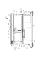
図1~図4に示すように、天びん1は、電磁平衡式やロードセル式などの質量センサ(図示省略)が収容されたハウジング50と、質量センサと連結されて試料が載置される秤量皿51とを有する。また、秤量皿51を囲むように環状壁52を設けている。ハウジング50の上面には風防10が設けられている。風防10は、秤量室Sを形成する外側風防11と、この外側風防11の内側に配置されて秤量皿51を覆う内側風防21とからなる。前記風防10は、秤量室Sの周囲の空気の流動、たとえばエアコンの風、秤量時の人の息、人が歩くときに発生する空気の流れなど、が秤量皿51を中心とした荷重負荷部分に風圧として作用して、計量に影響を与えるのを防ぐものである。
As shown in FIGS. 1 to 4, the balance 1 has a housing 50 in which a mass sensor (not shown) such as an electromagnetic equilibrium type or a load cell type is housed, and a weighing pan in which a sample is placed in connection with the mass sensor. It has 51 and. Further, an annular wall 52 is provided so as to surround the weighing pan 51. A windshield 10 is provided on the upper surface of the housing 50. The windshield 10 includes an outer windshield 11 forming a weighing chamber S and an inner windshield 21 arranged inside the outer windshield 11 and covering the weighing pan 51. The windshield 10 is a load-bearing portion centered on the weighing pan 51, such as the flow of air around the weighing chamber S, such as the wind of an air conditioner, the breath of a person during weighing, and the flow of air generated when a person walks. It acts as a wind pressure to prevent the measurement from being affected.
外側風防11は、正面板12と、側面をそれぞれ開閉する左右一対のスライド扉13,13と、上面を開閉する上面扉14と、背面を閉塞する箱型のケース15の一面を形成する背面板16を有し、ほぼ直方体状の秤量室Sを形成する。前記正面板12、前記一対のスライド扉13,13及び前記上面扉14は、ガラスまたは樹脂からなり、内部の状態が観察可能なように透明であることが望ましい。また、静電気の発生を防止するために、ガラスは表面に導電膜を設けた導電ガラス、樹脂は導電性を有する導電樹脂が望ましい。なお、前記外側風防11は、ハウジング50に公知の着脱機構によって着脱可能に設けても良いし、着脱不能に固定しても良い。
The outer windshield 11 forms a front plate 12, a pair of left and right slide doors 13 and 13 that open and close the side surfaces, a top door 14 that opens and closes the upper surface, and a back plate that forms one surface of a box-shaped case 15 that closes the back surface. 16 to form a nearly rectangular parallelepiped weighing chamber S. It is desirable that the front plate 12, the pair of slide doors 13, 13 and the upper surface door 14 are made of glass or resin and are transparent so that the internal state can be observed. Further, in order to prevent the generation of static electricity, it is desirable that the glass is a conductive glass having a conductive film on the surface and the resin is a conductive resin having conductivity. The outer windshield 11 may be detachably provided on the housing 50 by a known detachable mechanism, or may be fixed so as not to be detachable.
次いで、左右一対のスライド扉13,13について説明するが、各スライド扉13,13は同一構成なので、一方のみについて説明する。図1及び図2に示すように、スライド扉13は四角状の外枠13aを有し、外枠13aの上部が上面扉14の一側部に沿って設けた上部フレーム31とシリンダボックス32とに摺動可能に支持されて、吊持されている。スライド扉13は、シリンダボックス32内に配置したエアシリンダ(図示せず)の駆動力で往復移動するよう構成されている。この往復移動は、外枠13aの下部が下部フレーム33の水平部33aと立ち上り部33bで形成される断面L字状の案内レール34に案内されてなされる。スライド扉13の外枠13aの下端は、下部フレーム33の水平部33aから離反した非接触状態にあると好適である。なお、スライド扉13は、エアシリンダの駆動力で往復移動するほか、手動でも往復移動可能であり、手動で移動するために、正面板12側に取っ手13bが設けられている。
Next, a pair of left and right slide doors 13, 13 will be described, but since each slide door 13, 13 has the same configuration, only one of them will be described. As shown in FIGS. 1 and 2, the slide door 13 has a square outer frame 13a, and the upper portion of the outer frame 13a includes an upper frame 31 and a cylinder box 32 provided along one side of the upper surface door 14. It is slidably supported and suspended. The slide door 13 is configured to reciprocate by the driving force of an air cylinder (not shown) arranged in the cylinder box 32. This reciprocating motion is performed by being guided by a guide rail 34 having an L-shaped cross section formed by the horizontal portion 33a and the rising portion 33b of the lower frame 33 at the lower portion of the outer frame 13a. It is preferable that the lower end of the outer frame 13a of the slide door 13 is in a non-contact state separated from the horizontal portion 33a of the lower frame 33. The slide door 13 can be reciprocated by the driving force of the air cylinder and can also be reciprocated manually. In order to move the slide door 13 manually, a handle 13b is provided on the front plate 12 side.
図1で最もよく理解できるように、上面扉14はシリンダボックス32,32に設けられた図示しない案内溝に沿って、前後方向に往復移動可能に構成されている。前記上面扉14には、手動で移動するために、ケース15側に取っ手14aが設けられている。
As can be best understood in FIG. 1, the upper door 14 is configured to be reciprocating in the front-rear direction along a guide groove (not shown) provided in the cylinder boxes 32 and 32. The upper door 14 is provided with a handle 14a on the case 15 side for manual movement.
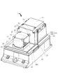
図1~図4に示すように、下部フレーム33の水平部33aには、各スライド扉13,13の移動経路に沿った位置に、前記各スライド扉13,13の下端が、下部フレーム33の立ち上り部33b、すなわち案内レール34の垂直部分、に対する離反方向に変位しないように規制する規制突起35,35を、各スライド扉13,13に毎に設けている。この規制突起35,35の形状は、図では明確ではないが八角柱である。前記規制突起35,35は、その側面において、前記各スライド扉13,13が閉鎖状態にあっても、開放状態にあっても、常に対応する前記スライド扉13,13の下端部分と接触できる位置にある。この規制突起35,35によって、案内レール34の水平部33aとは非接触状態にあるスライド扉13,13の下部のばたつきを防止し、スライド扉13,13の円滑な移動を確保する。また、前記規制突起35,35は常に対応する前記スライド扉13,13の下端部分と接触できる位置にあるので、前記ばたつきの防止は各スライド扉13,13の移動の全範囲において確実になされる。なお、前記各規制突起35,35の形状は八角柱のほか、他の多角柱や円柱であっても良い。
As shown in FIGS. 1 to 4, in the horizontal portion 33a of the lower frame 33, the lower ends of the slide doors 13 and 13 are located on the lower frame 33 at positions along the movement paths of the slide doors 13 and 13. Each of the slide doors 13 and 13 is provided with regulating protrusions 35 and 35 that regulate the rising portion 33b, that is, the vertical portion of the guide rail 34 so as not to be displaced in the direction of separation. The shapes of the regulating protrusions 35 and 35 are octagonal columns, although they are not clear in the figure. The regulation protrusions 35, 35 are located on the side surface thereof so that they can always come into contact with the lower end portions of the corresponding slide doors 13, 13 regardless of whether the slide doors 13, 13 are in the closed state or the open state. It is in. The regulating protrusions 35 and 35 prevent the lower portions of the slide doors 13 and 13 in a non-contact state with the horizontal portion 33a of the guide rail 34 from fluttering, and ensure smooth movement of the slide doors 13 and 13. Further, since the regulation protrusions 35, 35 are always in contact with the lower end portions of the corresponding slide doors 13, 13, the fluttering prevention is ensured in the entire range of movement of the slide doors 13, 13. .. In addition to the octagonal prism, the shape of each of the regulation protrusions 35, 35 may be another polygonal column or a cylinder.
図2~図4に示すように、内側風防21は、正面板22と、上面板23と、側面板24と、背面板25と、側面の一方が開放されてなる開口部26を有する。前記正面板22、前記側面板24、前記背面板25の各上端隅部は、前記上面板23の四隅部と樹脂製の固定具27,27,27,27で連結固定されている。また、前記正面板22、前記側面板24、前記背面板25の各下端隅部は、樹脂製で四角形状の固定枠28で固定されている。そして、前記内側風防21は一面が開口された直方体状を形成する。
As shown in FIGS. 2 to 4, the inner windshield 21 has a front plate 22, a top plate 23, a side plate 24, a back plate 25, and an opening 26 in which one of the side surfaces is open. The upper end corners of the front plate 22, the side plate 24, and the back plate 25 are connected and fixed to the four corners of the top plate 23 by resin fixtures 27, 27, 27, 27. Further, the lower end corners of the front plate 22, the side plate 24, and the back plate 25 are made of resin and fixed by a rectangular fixing frame 28. Then, the inner windshield 21 forms a rectangular parallelepiped shape with one side open.
内側風防21は、固定枠28によって下部フレーム33の上面板36に、秤量皿51を覆うようにして、開口部26が右側面側のスライド扉13と向き合うように配置され、公知の着脱機構(図示せず)によって着脱可能に取り付けられている。したがって、内側風防21を、開口部26が他方のスライド扉13(図2参照)と向き合うように配置することもできる。そして、固定枠28の開口部26の下部に対応位置する部分が遮蔽壁28aを構成する。この遮蔽壁28aの上端の高さ位置は、前記秤量皿51の高さ位置とほぼ同一高さにある。通常、前記遮蔽壁28aの上端の高さ位置は、前記秤量皿51の高さ位置と同一または若干高い位置にあり、内側風防21内への空気の流入阻止をより確実なものとしている。一方、前記遮蔽壁28aの上端の高さ位置が、前記秤量皿51の高さ位置よりも若干低い位置にあると、確実性は下がるものの前記流入阻止機能は維持できる。そしてこの場合は、主として元素分析用の液体や粉体の試料を入れたボートと称されるアルミ箔製、セラミック製、白金製等のボート型の浅い容器を、ピンセットでつまんで水平方向に移動して、試料をこぼすことなく秤量皿51上に載置する際に、前記遮蔽壁28aが邪魔にならず作業を容易かつ確実になし得る。
The inner windshield 21 is arranged on the upper surface plate 36 of the lower frame 33 by a fixed frame 28 so that the opening 26 faces the slide door 13 on the right side surface so as to cover the weighing pan 51, and a known attachment / detachment mechanism ( It is detachably attached by (not shown). Therefore, the inner windshield 21 can be arranged so that the opening 26 faces the other slide door 13 (see FIG. 2). A portion corresponding to the lower portion of the opening 26 of the fixed frame 28 constitutes the shielding wall 28a. The height position of the upper end of the shielding wall 28a is substantially the same as the height position of the weighing pan 51. Normally, the height position of the upper end of the shielding wall 28a is the same as or slightly higher than the height position of the weighing pan 51, which makes it more reliable to prevent the inflow of air into the inner windshield 21. On the other hand, if the height position of the upper end of the shielding wall 28a is slightly lower than the height position of the weighing pan 51, the inflow blocking function can be maintained although the certainty is lowered. In this case, a shallow boat-shaped container made of aluminum foil, ceramic, platinum, etc., which is mainly called a boat containing liquid or powder samples for elemental analysis, is pinched with tweezers and moved horizontally. Then, when the sample is placed on the weighing pan 51 without spilling, the shielding wall 28a does not get in the way and the work can be easily and surely performed.
内側風防21の正面板22、上面板23、側面板24、背面板25は、ガラスまたは樹脂からなり、内部の状態が観察可能なように透明であることが望ましい。また、静電気の発生を防止するために、ガラスは表面に導電膜を設けた導電ガラス、樹脂は導電性を有する導電樹脂が望ましい。
It is desirable that the front plate 22, the top plate 23, the side plate 24, and the back plate 25 of the inner windshield 21 are made of glass or resin and are transparent so that the internal state can be observed. Further, in order to prevent the generation of static electricity, it is desirable that the glass is a conductive glass having a conductive film on the surface and the resin is a conductive resin having conductivity.
以上の構成において、計量にあたっては、図2に示すように、外側風防11の右側面のスライド扉13を開いて、開放された側面から、内側風防21の開口部26を通して、秤量皿51上に試料を載置したうえ、前記スライド扉13を閉じて秤量室Sを閉塞状態として行う。この計量時には、秤量室Sは閉塞状態にあるので外部の影響を受けることがない。
In the above configuration, in weighing, as shown in FIG. 2, the slide door 13 on the right side of the outer windshield 11 is opened, and from the opened side surface, through the opening 26 of the inner windshield 21, onto the weighing pan 51. After placing the sample, the slide door 13 is closed and the weighing chamber S is closed. At the time of this weighing, the weighing chamber S is in a closed state and is not affected by the outside.
試料の計量に際して、試料を秤量皿51に載置するために、スライド扉13を開閉する動作時に、下部フレーム33の上面板36に沿って空気が風防10内に流入する可能性がある。しかし、空気が外側風防11から内側風防21に向けて秤量皿51方向に流動しても、空気は内側風防21の遮蔽壁28aに阻止されて固定枠28に沿って側面板24方向に流動することになるので、内側風防21内に流入することはなく、秤量皿51に達することはない。したがって、試料を載置した秤量皿51は常に空気の流れの影響を受けることなく、正確な計量がなされる。また、この空気の流れとともに粉塵が流入しても、同様にして粉塵が前記内側風防21内に流入することはない。
When weighing the sample, air may flow into the windshield 10 along the upper surface plate 36 of the lower frame 33 when the slide door 13 is opened and closed in order to place the sample on the weighing pan 51. However, even if the air flows from the outer windshield 11 toward the inner windshield 21 toward the weighing pan 51, the air is blocked by the shielding wall 28a of the inner windshield 21 and flows toward the side plate 24 along the fixed frame 28. Therefore, it does not flow into the inner windshield 21 and does not reach the weighing pan 51. Therefore, the weighing pan 51 on which the sample is placed is not always affected by the air flow, and accurate weighing is performed. Further, even if dust flows in along with this air flow, the dust does not flow into the inner windshield 21 in the same manner.
また、左側面側のスライド扉13(図2参照)を開放して計量作業を行いたい場合には、内側風防21の開口部26を当該スライド扉と向き合うようにする必要がある。このため、内側風防21を上面板36から一旦取り外し、開口部26の向きが反対になるようにして、前記内側風防21を前記上面板36に取り付ける。そして、外側風防10の左側面のスライド扉13を開いて、開放された側面から、内側風防21の開口部26を通して、秤量皿51上に試料を載置したうえ、前記スライド扉13を閉じて秤量室Sを閉塞状態とし、計量を行うことができる。
If it is desired to open the slide door 13 (see FIG. 2) on the left side to perform weighing work, it is necessary to make the opening 26 of the inner windshield 21 face the slide door. Therefore, the inner windshield 21 is temporarily removed from the upper surface plate 36, and the inner windshield 21 is attached to the upper surface plate 36 so that the directions of the openings 26 are opposite to each other. Then, the slide door 13 on the left side surface of the outer windshield 10 is opened, the sample is placed on the weighing pan 51 from the opened side surface through the opening 26 of the inner windshield 21, and then the slide door 13 is closed. Weighing can be performed with the weighing chamber S closed.
なお、本発明は上述の実施形態に限定されず、例えば、外側風防11と内側風防21の形状は直方体状に限らず、ともに上面を閉塞した円筒形状でもよい。また、外側風防11が直方体状で、内側風防21は平面形状U字状の箱体としてもよい。この平面形状U字状の箱体の内側風防21は直方体状と同様に、円筒形状と比較して開口部を十分確保できるので好適である。内側風防21を回転可能に構成した場合には、内側風防を所定方向に回転することで、内側風防21の開口部26を外側風防11の希望する側のスライド扉13と向い合せることができる。この回転可能な構成は、従来公知の手段を用いて実現可能である。
The present invention is not limited to the above-described embodiment. For example, the outer windshield 11 and the inner windshield 21 are not limited to a rectangular parallelepiped shape, and may both have a cylindrical shape with an upper surface closed. Further, the outer windshield 11 may have a rectangular parallelepiped shape, and the inner windshield 21 may have a planar U-shaped box body. The inner windshield 21 of this planar U-shaped box is suitable because it can sufficiently secure an opening as compared with the cylindrical shape, as in the rectangular parallelepiped shape. When the inner windshield 21 is configured to be rotatable, the opening 26 of the inner windshield 21 can be made to face the slide door 13 on the desired side of the outer windshield 11 by rotating the inner windshield in a predetermined direction. This rotatable configuration can be realized using conventionally known means.
また、環状壁52も空気流及びそれに伴う粉塵の秤量皿51への到達を阻止する機能を有するが、本発明においては、遮蔽壁28aによって内側風防21内への空気の流入を阻止するので、この環状壁52は必ずしも設ける必要はないものである。
Further, the annular wall 52 also has a function of blocking the air flow and the accompanying dust from reaching the weighing pan 51. However, in the present invention, the shielding wall 28a blocks the inflow of air into the inner windshield 21. The annular wall 52 does not necessarily have to be provided.
1 天びん
10 風防
11 外側風防
12 正面板
13 スライド扉
14 上面扉
16 背面板
21 内側風防
22 正面板
23 上面板
24 側面板
25 背面板
26 開口部
27 固定具
28 固定枠
28a 遮蔽壁
34 案内レール
50 ハウジング
51 秤量皿
S 秤量室 1Balance 10 Windshield 11 Outer windshield 12 Front plate 13 Slide door 14 Top door 16 Back plate 21 Inner windshield 22 Front plate 23 Top plate 24 Side plate 25 Back plate 26 Opening 27 Fixture 28 Fixture 28 a Shielding wall 34 Guide rail 50 Housing 51 Weighing dish S Weighing chamber
10 風防
11 外側風防
12 正面板
13 スライド扉
14 上面扉
16 背面板
21 内側風防
22 正面板
23 上面板
24 側面板
25 背面板
26 開口部
27 固定具
28 固定枠
28a 遮蔽壁
34 案内レール
50 ハウジング
51 秤量皿
S 秤量室 1
Claims (4)
- 秤量室を形成する外側風防と、この外側風防の内側に配置されて秤量皿を覆う内側風防と、を備え、
前記外側風防は、側面に開閉可能なスライド扉を有し、
前記内側風防は、前記スライド扉に向き合う面が開口されて開口部となり、この開口部の下部には遮蔽壁を有する
天びん用風防。 It comprises an outer windshield that forms a weighing chamber and an inner windshield that is located inside this outer windshield and covers the weighing pan.
The outer windshield has a sliding door that can be opened and closed on the side surface.
The inner windshield has an opening on the surface facing the slide door, and a windshield for a balance having a shielding wall below the opening. - 前記遮蔽壁の上端は、前記秤量皿の高さ位置とほぼ同一高さ位置にある
請求項1に記載の天びん用風防。 The windshield for a balance according to claim 1, wherein the upper end of the shielding wall is located at a height substantially the same as the height position of the weighing pan. - 前記スライド扉は、外側風防の一対の側面にそれぞれ設けられ、
前記内側風防は着脱可能に設けられ、その開口部が前記スライド扉の一方と向き合うように設置される
請求項1または請求項2に記載の天びん用風防。 The slide doors are provided on a pair of side surfaces of the outer windshield, respectively.
The windshield for a balance according to claim 1 or 2, wherein the inner windshield is detachably provided and the opening thereof is installed so as to face one of the slide doors. - 前記スライド扉は、外側風防の一対の側面にそれぞれ設けられ、
前記内側風防は回転可能に設けられ、その開口部が前記スライド扉の一方と向き合うように設置される
請求項1または請求項2に記載の天びん用風防。 The slide doors are provided on a pair of side surfaces of the outer windshield, respectively.
The windshield for a balance according to claim 1 or 2, wherein the inner windshield is rotatably provided and the opening thereof is installed so as to face one of the slide doors.
Priority Applications (5)
| Application Number | Priority Date | Filing Date | Title |
|---|---|---|---|
| CN202080102879.4A CN115803593A (en) | 2020-07-06 | 2020-07-06 | Windshield for balance |
| EP20943842.3A EP4177580A4 (en) | 2020-07-06 | 2020-07-06 | Wind screen for balance scale |
| US18/012,197 US20230304848A1 (en) | 2020-07-06 | 2020-07-06 | Windshield for balance |
| PCT/JP2020/026409 WO2022009266A1 (en) | 2020-07-06 | 2020-07-06 | Wind screen for balance scale |
| JP2022518182A JP7105396B2 (en) | 2020-07-06 | 2020-07-06 | Wind shield for balance |
Applications Claiming Priority (1)
| Application Number | Priority Date | Filing Date | Title |
|---|---|---|---|
| PCT/JP2020/026409 WO2022009266A1 (en) | 2020-07-06 | 2020-07-06 | Wind screen for balance scale |
Publications (1)
| Publication Number | Publication Date |
|---|---|
| WO2022009266A1 true WO2022009266A1 (en) | 2022-01-13 |
Family
ID=79553009
Family Applications (1)
| Application Number | Title | Priority Date | Filing Date |
|---|---|---|---|
| PCT/JP2020/026409 WO2022009266A1 (en) | 2020-07-06 | 2020-07-06 | Wind screen for balance scale |
Country Status (5)
| Country | Link |
|---|---|
| US (1) | US20230304848A1 (en) |
| EP (1) | EP4177580A4 (en) |
| JP (1) | JP7105396B2 (en) |
| CN (1) | CN115803593A (en) |
| WO (1) | WO2022009266A1 (en) |
Citations (5)
| Publication number | Priority date | Publication date | Assignee | Title |
|---|---|---|---|---|
| JPH0562825U (en) * | 1992-01-31 | 1993-08-20 | 株式会社島津製作所 | Balance with draft shield |
| JPH05322638A (en) | 1992-05-22 | 1993-12-07 | Shimadzu Corp | Balance equipped with windshield |
| JPH0783744A (en) * | 1993-09-10 | 1995-03-31 | A & D Co Ltd | Electronic balance |
| JP2009036583A (en) * | 2007-07-31 | 2009-02-19 | Shimadzu Corp | Electronic balance/electronic weighing instrument |
| US20180106665A1 (en) * | 2015-05-22 | 2018-04-19 | Sartorius Lab Instruments Gmbh & Co. Kg | Weighing apparatus with proximity sensor |
Family Cites Families (6)
| Publication number | Priority date | Publication date | Assignee | Title |
|---|---|---|---|---|
| JPH0756460B2 (en) * | 1986-02-04 | 1995-06-14 | 株式会社エー・アンド・デイ | High resolution weighing device |
| JP2822671B2 (en) * | 1990-12-25 | 1998-11-11 | 株式会社島津製作所 | Electronic balance |
| CN102466512A (en) | 2010-11-15 | 2012-05-23 | 常熟市佳衡天平仪器有限公司 | Electronic balance with windshield |
| CN203551084U (en) | 2013-11-07 | 2014-04-16 | 奥豪斯仪器(上海)有限公司 | Balance and windproof structure thereof |
| CN109374103B (en) | 2018-08-22 | 2021-02-26 | 湖北耀江环境工程有限公司 | Electronic balance protective cover |
| CN210689802U (en) | 2019-12-18 | 2020-06-05 | 河南盈科新材料有限公司 | Electronic balance for plastic weighing test |
-
2020
- 2020-07-06 JP JP2022518182A patent/JP7105396B2/en active Active
- 2020-07-06 EP EP20943842.3A patent/EP4177580A4/en active Pending
- 2020-07-06 CN CN202080102879.4A patent/CN115803593A/en active Pending
- 2020-07-06 US US18/012,197 patent/US20230304848A1/en active Pending
- 2020-07-06 WO PCT/JP2020/026409 patent/WO2022009266A1/en unknown
Patent Citations (5)
| Publication number | Priority date | Publication date | Assignee | Title |
|---|---|---|---|---|
| JPH0562825U (en) * | 1992-01-31 | 1993-08-20 | 株式会社島津製作所 | Balance with draft shield |
| JPH05322638A (en) | 1992-05-22 | 1993-12-07 | Shimadzu Corp | Balance equipped with windshield |
| JPH0783744A (en) * | 1993-09-10 | 1995-03-31 | A & D Co Ltd | Electronic balance |
| JP2009036583A (en) * | 2007-07-31 | 2009-02-19 | Shimadzu Corp | Electronic balance/electronic weighing instrument |
| US20180106665A1 (en) * | 2015-05-22 | 2018-04-19 | Sartorius Lab Instruments Gmbh & Co. Kg | Weighing apparatus with proximity sensor |
Also Published As
| Publication number | Publication date |
|---|---|
| JPWO2022009266A1 (en) | 2022-01-13 |
| EP4177580A4 (en) | 2023-07-26 |
| CN115803593A (en) | 2023-03-14 |
| JP7105396B2 (en) | 2022-07-22 |
| US20230304848A1 (en) | 2023-09-28 |
| EP4177580A1 (en) | 2023-05-10 |
Similar Documents
| Publication | Publication Date | Title |
|---|---|---|
| JPH0225144Y2 (en) | ||
| JP5520127B2 (en) | Anti-ventilation device for laboratory equipment | |
| US9121749B2 (en) | Weighing device having a weighing chamber | |
| US11002591B2 (en) | Laboratory balance with a weighing chamber rear wall of modular construction | |
| CN100395524C (en) | Scale with wind protected means | |
| JP5368364B2 (en) | Anti-ventilation device for laboratory equipment | |
| CN101669015B (en) | Windshield for weighing device | |
| US20060284064A1 (en) | Door assembly for a semi-automatic micro-hole plate single-photon counter | |
| CN110388978B (en) | Laboratory weighing device with motorized windshield | |
| US11054300B2 (en) | Weighing device with a movable mounting unit | |
| WO2022009266A1 (en) | Wind screen for balance scale | |
| US10871392B2 (en) | Protective cover for weighing instrument with suspended sliding door | |
| US20200284645A1 (en) | Weighing balance having a mounting unit for carrying accessories | |
| JPS62169024A (en) | Even type analytical balance | |
| JPH0749988B2 (en) | Balance with windshield | |
| US20190025221A1 (en) | Chemiluminescence detector | |
| JPH0562825U (en) | Balance with draft shield | |
| CN208350196U (en) | A kind of hurricane globe of electronic analytical balance | |
| JP7255074B2 (en) | Shape measuring device | |
| JPWO2022009266A5 (en) | ||
| JP5195596B2 (en) | electronic balance | |
| US1591488A (en) | Sealing device | |
| JPH1019650A (en) | Scale fitted with windshield | |
| FR3073942B1 (en) | AMBIENT AIR QUALITY MEASURING BOX WITH AIR INTAKE LIGHTS DESIGNED TO AVOID THE INTRODUCTION OF RAIN, AND ASSOCIATED MEASUREMENT MODULE | |
| WO2005085778A1 (en) | Windshield device for scale |
Legal Events
| Date | Code | Title | Description |
|---|---|---|---|
| 121 | Ep: the epo has been informed by wipo that ep was designated in this application |
Ref document number: 20943842 Country of ref document: EP Kind code of ref document: A1 |
|
| ENP | Entry into the national phase |
Ref document number: 2022518182 Country of ref document: JP Kind code of ref document: A |
|
| NENP | Non-entry into the national phase |
Ref country code: DE |
|
| ENP | Entry into the national phase |
Ref document number: 2020943842 Country of ref document: EP Effective date: 20230206 |