WO2022004705A1 - 教示装置及びコンピュータプログラム - Google Patents
教示装置及びコンピュータプログラム Download PDFInfo
- Publication number
- WO2022004705A1 WO2022004705A1 PCT/JP2021/024494 JP2021024494W WO2022004705A1 WO 2022004705 A1 WO2022004705 A1 WO 2022004705A1 JP 2021024494 W JP2021024494 W JP 2021024494W WO 2022004705 A1 WO2022004705 A1 WO 2022004705A1
- Authority
- WO
- WIPO (PCT)
- Prior art keywords
- rotary dial
- operation amount
- industrial machine
- scale
- rotation operation
- Prior art date
- Legal status (The legal status is an assumption and is not a legal conclusion. Google has not performed a legal analysis and makes no representation as to the accuracy of the status listed.)
- Ceased
Links
Images


Classifications
-
- G—PHYSICS
- G05—CONTROLLING; REGULATING
- G05B—CONTROL OR REGULATING SYSTEMS IN GENERAL; FUNCTIONAL ELEMENTS OF SUCH SYSTEMS; MONITORING OR TESTING ARRANGEMENTS FOR SUCH SYSTEMS OR ELEMENTS
- G05B19/00—Program-control systems
- G05B19/02—Program-control systems electric
- G05B19/42—Recording and playback systems, i.e. in which the program is recorded from a cycle of operations, e.g. the cycle of operations being manually controlled, after which this record is played back on the same machine
-
- B—PERFORMING OPERATIONS; TRANSPORTING
- B25—HAND TOOLS; PORTABLE POWER-DRIVEN TOOLS; MANIPULATORS
- B25J—MANIPULATORS; CHAMBERS PROVIDED WITH MANIPULATION DEVICES
- B25J9/00—Program-controlled manipulators
- B25J9/16—Program controls
- B25J9/1656—Program controls characterised by programming, planning systems for manipulators
- B25J9/1664—Program controls characterised by programming, planning systems for manipulators characterised by motion, path, trajectory planning
-
- G—PHYSICS
- G05—CONTROLLING; REGULATING
- G05B—CONTROL OR REGULATING SYSTEMS IN GENERAL; FUNCTIONAL ELEMENTS OF SUCH SYSTEMS; MONITORING OR TESTING ARRANGEMENTS FOR SUCH SYSTEMS OR ELEMENTS
- G05B19/00—Program-control systems
- G05B19/02—Program-control systems electric
- G05B19/18—Numerical control [NC], i.e. automatically operating machines, in particular machine tools, e.g. in a manufacturing environment, so as to execute positioning, movement or co-ordinated operations by means of program data in numerical form
- G05B19/409—Numerical control [NC], i.e. automatically operating machines, in particular machine tools, e.g. in a manufacturing environment, so as to execute positioning, movement or co-ordinated operations by means of program data in numerical form characterised by using manual data input [MDI] or by using control panel, e.g. controlling functions with the panel; characterised by control panel details or by setting parameters
-
- G—PHYSICS
- G05—CONTROLLING; REGULATING
- G05B—CONTROL OR REGULATING SYSTEMS IN GENERAL; FUNCTIONAL ELEMENTS OF SUCH SYSTEMS; MONITORING OR TESTING ARRANGEMENTS FOR SUCH SYSTEMS OR ELEMENTS
- G05B19/00—Program-control systems
- G05B19/02—Program-control systems electric
- G05B19/42—Recording and playback systems, i.e. in which the program is recorded from a cycle of operations, e.g. the cycle of operations being manually controlled, after which this record is played back on the same machine
- G05B19/425—Teaching successive positions by numerical control, i.e. commands being entered to control the positioning servo of the tool head or end effector
-
- G—PHYSICS
- G06—COMPUTING OR CALCULATING; COUNTING
- G06F—ELECTRIC DIGITAL DATA PROCESSING
- G06F3/00—Input arrangements for transferring data to be processed into a form capable of being handled by the computer; Output arrangements for transferring data from processing unit to output unit, e.g. interface arrangements
- G06F3/01—Input arrangements or combined input and output arrangements for interaction between user and computer
- G06F3/048—Interaction techniques based on graphical user interfaces [GUI]
- G06F3/0484—Interaction techniques based on graphical user interfaces [GUI] for the control of specific functions or operations, e.g. selecting or manipulating an object, an image or a displayed text element, setting a parameter value or selecting a range
- G06F3/04847—Interaction techniques to control parameter settings, e.g. interaction with sliders or dials
-
- G—PHYSICS
- G05—CONTROLLING; REGULATING
- G05B—CONTROL OR REGULATING SYSTEMS IN GENERAL; FUNCTIONAL ELEMENTS OF SUCH SYSTEMS; MONITORING OR TESTING ARRANGEMENTS FOR SUCH SYSTEMS OR ELEMENTS
- G05B2219/00—Program-control systems
- G05B2219/30—Nc systems
- G05B2219/35—Nc in input of data, input till input file format
- G05B2219/35409—DPC direct programming at the console
-
- G—PHYSICS
- G05—CONTROLLING; REGULATING
- G05B—CONTROL OR REGULATING SYSTEMS IN GENERAL; FUNCTIONAL ELEMENTS OF SUCH SYSTEMS; MONITORING OR TESTING ARRANGEMENTS FOR SUCH SYSTEMS OR ELEMENTS
- G05B2219/00—Program-control systems
- G05B2219/30—Nc systems
- G05B2219/39—Robotics, robotics to robotics hand
- G05B2219/39438—Direct programming at the console
-
- G—PHYSICS
- G05—CONTROLLING; REGULATING
- G05B—CONTROL OR REGULATING SYSTEMS IN GENERAL; FUNCTIONAL ELEMENTS OF SUCH SYSTEMS; MONITORING OR TESTING ARRANGEMENTS FOR SUCH SYSTEMS OR ELEMENTS
- G05B2219/00—Program-control systems
- G05B2219/30—Nc systems
- G05B2219/40—Robotics, robotics mapping to robotics vision
- G05B2219/40392—Programming, visual robot programming language
Definitions
- the present invention relates to a teaching device and a computer program in various operation processing devices, particularly a teaching device and a computer program operated on a touch panel.
- the rotary dial device is not installed on the operation panel as a teaching device for robots, so it is necessary to prepare it separately. It is also conceivable to display a rotary dial on a device with a touch panel such as a tablet to operate the robot. However, since the operation of displaying the rotary dial on such a device with a touch panel is an operation on the screen, the operation feeling of the rotary dial device cannot be obtained, and the operation amount is erroneously specified. There is a possibility that it will end up. This is a problem that occurs not only in the teaching device of a robot but also in the teaching device of other industrial machines such as machine tools.
- the operation amount is specified accurately without erroneously operating the operation amount. Therefore, it is required to obtain a feeling of operation and improve operability.
- the teaching device of the present disclosure is a teaching device provided with a touch panel type display screen as an input interface in an industrial machine, and an operator can rotate the display screen.
- a rotary dial display unit that displays a rotary dial with a scale for the rotation operation amount, and a rotation operation amount acquisition unit that acquires a rotation operation amount in which the operator rotates the rotary dial.
- a sound effect or vibration is generated every time the rotation amount of one scale of the rotary dial is rotated, so that the operator operates how many scales. It can be obtained as a feeling of operation. Therefore, it is possible to avoid erroneous recognition of the operation amount caused by the lack of operation feeling, and it is possible to obtain a teaching device with improved operability.
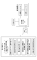
- FIG. 1 is a configuration diagram showing a relationship between a robot, a control device, and a teaching device according to one embodiment of the present disclosure.
- the robot 1 in FIG. 1 is an articulated robot having an articulated arm, and can perform orthogonal motion and rotational motion. Due to the limitation of the mechanical part of the robot, the upper limit value and the lower limit value are set for the movement distance in the orthogonal operation and the rotation angle in the rotation operation for each operation axis, and each operation axis is operated within a certain range. ..
- the control device 2 is a processing unit (CPU) 21 composed of a microcomputer or the like, a storage unit 22 including a memory member such as a ROM or RAM, and a transmission / reception unit 23 for transmitting / receiving signals to / from the robot 1 and the teaching device 3.
- the teaching device 3 is a teaching operation panel provided with a touch panel, and transmits a teaching signal about the operation of the robot 1 to the control device 2 based on an input by an operator from the touch panel.
- the teaching device 3 includes a rotary dial display unit 301, a rotation operation amount acquisition unit 302, an operation amount designation unit 303, a sound effect or vibration transmission unit 304, an operation coordinate system and an operation axis selection unit 305, and a one-scale operation.
- the amount setting unit 306 is provided.
- FIG. 2 is a configuration diagram showing a relationship between a robot, a control device, and a teaching device according to another embodiment of the present disclosure.
- the teaching device 3 is connected to the control device 2 by wire in FIG. 1, but in FIG. 2, the teaching device 3 is connected to the control device 2. Is the point of being connected wirelessly. Therefore, in the embodiment of FIG. 2, the teaching device 3 is not limited to the teaching operation panel provided with the touch panel, and may be a tablet.
- a Wi-Fi router for wireless communication with the teaching device 3 is connected to the control device 2.
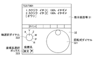
- FIG. 3 shows one embodiment of the display screen of the teaching device 3.
- the display screen of the teaching device 3 is roughly divided into a teaching screen 31 and an operation screen 32.
- the axis selected in the operation of the robot 1 and the content of the taught position as a result of the operation of the robot 1 are described in text.
- the operation screen 32 is arranged below the teaching screen 31.
- the rotary dial display unit 301 displays the rotary dial 321 in the operation screen 32.
- the axis selection dial 322 and the coordinate system selection box 323 are set and displayed on the operation screen 32.
- the rotary dial 321 operates the robot 1 in the direction of the selected axis in the coordinate system selected by the operation coordinate system and the operation axis selection unit 305 by rotating the rotary dial of the image on the display screen. It is a means to make it. From the rotation operation of the rotary dial to the operation of the robot, the rotation operation amount acquisition unit 302 acquires the rotation operation amount in which the operator rotates the rotary dial, and the operation amount designation unit 303 is based on the acquired rotation operation amount. Specifies the amount of movement of the robot 1, and the processing procedure is that the robot 1 is operated with the specified amount of movement.
- the axis selection dial 322 is for the operator to select the operation axis selected by the operation coordinate system and the operation axis selection unit 305. In FIG.
- the linear movement axis of XYZ and the rotation axis of WPR are used. It is a dial-type selection means for selecting an axis.
- the coordinate system selection box 323 allows the operator to select the operating coordinate system selected by the operating coordinate system and the operating axis selection unit 305 from the pull-down menu.
- a Cartesian coordinate system or a rotating coordinate system is selected.
- a procedure for operating the robot 1 on the operation screen 32 first, a Cartesian coordinate system or a rotating coordinate system is selected from the coordinate system selection box 323.
- the axis displayed by the axis selection dial 322 changes according to the selected coordinate system.
- the robot 1 can be operated in the direction of the selected axis by rotating the rotary dial 321 after selecting the axis to be operated by the axis selection dial 322.
- FIG. 4 shows another embodiment of the display screen of the teaching device 3.
- the means for selecting the axis is the axis selection dial 322, but in FIG. 4, the axis selection button 332 is used.
- the axis selection button 332 displays the axes that can be selected when the icon of the axis selection button is clicked.
- the linear movement axis of XYZ and the rotation axis of WPR are displayed.
- the sound effect or vibration transmitting unit 304 emits a sound effect or vibration according to the amount of rotation operation. Specifically, a sound effect or vibration is emitted each time a rotation operation for one scale set on the rotary dial is performed. This is for the operator to recognize that the operation rotation amount is advanced by one scale of the rotary dial by the operation feeling by hearing or touch.
- the sound effect or vibration transmitting unit 304 emits the sound effect or vibration in different patterns during the orthogonal operation and the rotational operation. This is for the operator to recognize whether the robot is currently operated by an orthogonal motion or a rotary motion by a sense of operation by hearing or touch.
- a 1-scale operation amount setting unit 306 capable of setting an operation amount corresponding to 1 scale of the rotary dial 321 is provided, and the operation amount of the distance or angle corresponding to 1 scale of the rotary dial 321 can be determined by the operator or. It is set automatically. As described above, in the robot 1, the robot 1 is operated with a movement amount within a specific range for each movement axis. Further, the 1-scale operation amount setting unit 306 can automatically change the operation amount for one scale of the rotary dial 321 according to the difference from the distance or angle of the upper limit of the operating range. Near the upper limit of the operating range, it is expected that it will be difficult to reach outside the operating range by setting the operation amount for one scale small.
- the operation amount for one scale can be changed depending on the operation direction of the rotary dial 321 by the operator. In the direction in which the operation direction is toward the upper limit of the operation range of the robot 1 operation axis, the operation amount for one scale is set small, and in the direction of returning from the upper limit value of the operation range to the initial operation value, the operation amount for one scale is set. It is also possible to set a large amount of operation.
- the rotary dial display unit 301 changes the display of the rotary dial 321. At that time, the rotary dial display unit 301 prevents the rotary dial 321 from rotating. Further, the operation amount designation unit 303 stops the command to the robot 1 by the rotation operation of the rotary dial 321. Further, the sound effect or vibration transmitting unit 304 emits a sound effect or vibration different from that in the normal operation of the robot 1.
- the sound effect or vibration may be presented once when an abnormal state occurs, or may be presented at all times during the occurrence of an abnormal state. Further, by presenting the sound effect or vibration again when the rotary dial 321 is to be operated, the operator can be made to re-recognize that the robot cannot be manually operated in an abnormal state.
- the robot 1 cannot be operated by the rotation operation of the rotary dial 321.
- the rotary dial display unit 301 changes the rotary dial 321 to a display different from the usual one so that it does not rotate even when the operator tries to operate it.
- the operation amount designation unit 303 stops the command to the robot 1 by the rotation operation of the rotary dial 321. Further, when the rotary dial 321 is to be operated, the sound effect or vibration transmitting unit 304 emits a sound effect or vibration for automatic operation, which is different from the normal operation of the robot 1.
- the teaching screen 31 and the operation screen 32 are simultaneously displayed on the display screen.
- the operation of the robot 1 by the rotary dial 321 and the position teaching can be performed without switching the screen.
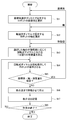
- the operator first selects the coordinate system of the robot 1 to be operated by the coordinate system selection box 323 on the operation screen 32 of the teaching device 3, and the robot is selected by the operation coordinate system and the operation axis selection unit 305.
- the coordinate system of 1 is selected (step St1).
- the operator selects the operation axis of the robot 1 to be operated by the axis selection dial 322 (or the axis selection button 332), and the operation axis of the robot 1 is selected by the operation coordinate system and the operation axis selection unit 305 (the operation axis of the robot 1 is selected.
- Step St2 the operation axis of the robot 1 is selected by the operation coordinate system and the operation axis selection unit 305.
- the operation amount for 1 scale on the rotary dial is set according to the operating range of the selected shaft (step St3).
- the operation amount for one scale is set small near the upper limit of the operating range.
- the operation amount for one scale is set small, and in the direction of returning from the upper limit value of the operation range to the initial operation value, one scale is set. It is also possible to set a large amount of operation for minutes.
- Step St4 the movement amount in the direction toward the upper limit value of the operating range is set small in step St3, it becomes easy to finely adjust the position in the movement in the direction toward the upper limit value of the operating range.
- step St5 it is determined whether or not it is necessary to set the coordinate system, the axis, and the movement amount while the robot 1 is being moved by the rotation operation of the rotary dial 321 (step St5). If the determination result of step St5 is YES, that is, if it becomes necessary to change any of the coordinate system, the axis, and the movement amount during the rotation operation of the rotary dial 321, the rotation operation of the rotary dial 321 is performed.
- Step St1 a coordinate system, an axis, or a movement amount
- step St6 the rotary dial 321 is stopped to stop the robot 1
- step St7 the current position of the robot 1 at that time is stored in the robot program as a teaching point.
- step St8 it is determined whether or not the work by the operation of the robot 1 is completed.
- step St8 determines whether or not the work by the operation of the robot 1 is completed.
- step St8 determines whether or not the work by the operation of the robot 1 is completed.
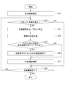
- the flow chart of FIG. 6 shows a procedure for performing recovery work with the rotary dial 321 when an abnormality occurs in the automatic operation of the robot 1 in the present disclosure.
- the rotary dial 321 changes to a color different from that in the normal operation, and the rotary dial 321 cannot be operated. Further, when the rotary dial 321 is to be operated, a sound effect / vibration different from that in the normal operation is emitted. Then, it is determined whether or not an abnormality has occurred in the robot 1 (step St2'). If the determination result is NO, that is, if no abnormality has occurred, the automatic operation proceeds and the process proceeds to step St8'.
- step St3' If the determination result of step St2'is YES, that is, if an abnormality occurs, the automatic operation of the robot 1 is stopped and the robot 1 is stopped (step St3'). Further, at that time, the rotary dial 321 changes to a color different from that in the normal operation, and the rotary dial 321 cannot be operated. Further, when an abnormality is occurring or when the rotary dial 321 is to be operated, a sound effect / vibration different from that during normal operation is emitted. Next, the operator confirms the content of the abnormality alarm, performs the abnormality recovery work, and eliminates the cause of the abnormality (step St4'). When the cause of the abnormality is eliminated, the color, sound effect, and vibration of the rotary dial 321 return to the normal state, and the robot 1 can be operated by the rotary dial 321.
- step St5' determines whether or not the robot 1 interferes with the work or peripheral devices when the automatic operation of the robot 1 is restarted. If the determination result is YES, that is, if the robot 1 may interfere with the work or peripheral devices, the rotary dial 321 is turned to retract the robot 1 (step St6'). After that, the automatic operation of the robot 1 is restarted (step St7'). After restarting, the color of the rotary dial 321 changes as in the case of St1', the rotary dial 321 cannot be operated, and when it is attempted to operate, a sound effect / vibration different from that in the normal operation is emitted. Then, it is determined whether or not to end the automatic operation of the robot 1 (step St8').
- step St2' the automatic operation of the robot 1 ends, and this flow ends. If the determination result is NO, the automatic operation of the robot 1 is continued, and the process returns to step St2'. Then, the loop from step St2'to step St8'is repeated until it is determined that the automatic operation is completed in step St8'.
- the robot when the robot performs both orthogonal motion and rotational motion by the rotational operation of the teaching device as in the teaching device of the present disclosure, the robot is changed from the orthogonal motion to the rotary motion and from the rotary motion to the orthogonal motion. When both operations are repeated, it becomes difficult to recognize which operation state is currently in, and as a result, there is a possibility of malfunction.
- the sound effect or vibration is emitted by changing the pattern between the orthogonal operation and the rotational operation, so that the operator can check whether the robot is currently operating in the orthogonal operation or the rotational operation. Whether it is operating can be recognized by a sense of operation by hearing or touch. Therefore, it is possible to avoid a malfunction due to an erroneous recognition of the operating state of the robot, and it is possible to improve the operability.
- the operation amount for one scale of the rotary dial can be automatically changed according to the difference from the distance or angle of the upper limit of the operating range. Therefore, in the direction in which the operation direction is toward the upper limit of the operation range of the operation axis, the operation amount for one scale is set small, and in the direction of returning from the upper limit value of the operation range to the initial operation value, the operation for one scale is set. You can also set a large amount. By setting in this way, it becomes difficult to reach outside the operating range, it is possible to avoid malfunctions that cause operation outside the operating range, and the speed is normal in the reverse direction from the vicinity outside the operating range. Since it can be returned with, it can be considered that the operability is high from the viewpoint of the operation speed.
- the display of the rotary dial is changed, the command to the robot by the rotation operation of the rotary dial is stopped, and the abnormal state is also obtained.
- a sound effect or vibration different from that during normal operation of the robot is emitted, so the operator quickly notices the abnormal state and continues the operation in the abnormal state. You can avoid that. As a result, it is possible to avoid continuing unnecessary operations, and it is possible to prevent the robot from being damaged by continuing operations in an abnormal state.
- the display of the rotary dial is changed and the command to the robot by the rotation operation of the rotary dial is stopped. Also, when trying to operate the rotary dial, a sound effect or vibration different from that during normal operation of the robot is emitted, so the operator notices that the robot is in automatic operation and operates it while it is in automatic operation. You can avoid trying to continue.
- the robot by displaying the teaching screen and the operation screen at the same time, the robot can be operated by the rotary dial and the position teaching can be performed without switching the screen, so that the position teaching can be recognized. It can be operated while the operation is performed, the operability is improved, and malfunction can be prevented.
- the present invention is not limited to these embodiments, and for example, the embodiments described in the robot have been described in other industries including various machine tools. It goes without saying that it can be carried out in various embodiments within a range that does not deviate from the gist of the present invention so that it can be applied to embodiments in machines.
- Robot 2 Control device 21 Processing unit 22 Storage unit 23 Transmission / reception unit 3
- Teaching device 301 Rotary dial display unit 302
- Rotary operation amount acquisition unit 303 Operation amount specification unit 304
- Sound effect or vibration transmission unit 305 Operation coordinate system and operation axis Selection unit 306
- Scale operation amount setting unit 31 Teaching screen 32 Operation screen 321 Rotary dial 322 Axis selection dial 323 Coordinate system selection box 332 Axis selection button
Landscapes
- Engineering & Computer Science (AREA)
- Physics & Mathematics (AREA)
- General Physics & Mathematics (AREA)
- Automation & Control Theory (AREA)
- Human Computer Interaction (AREA)
- General Engineering & Computer Science (AREA)
- Theoretical Computer Science (AREA)
- Manufacturing & Machinery (AREA)
- Robotics (AREA)
- Mechanical Engineering (AREA)
- Manipulator (AREA)
- Numerical Control (AREA)
Abstract
Description
2 制御装置
21 処理ユニット
22 記憶ユニット
23 送受信ユニット
3 教示装置
301 回転式ダイヤル表示部
302 回転操作量取得部
303 動作量指定部
304 効果音又は振動の発信部
305 動作座標系及び動作軸の選択部
306 1目盛り操作量設定部
31 教示画面
32 操作画面
321 回転式ダイヤル
322 軸選択ダイヤル
323 座標系選択ボックス
332 軸選択ボタン
Claims (12)
- 産業機械において入力インターフェースとなるタッチパネル式の表示画面を備えた教示装置であって、
前記タッチパネル式の表示画面に、操作者が回転操作することができ、回転操作量に対して目盛りが付されている回転式ダイヤルを表示する回転式ダイヤル表示部と、
操作者が前記回転式ダイヤルを回転操作した回転操作量を取得する回転操作量取得部と、
前記回転式ダイヤルの回転操作量によって前記産業機械の動作量を指定する動作量指定部と、
前記回転式ダイヤルの1目盛り分の回転操作量を回転操作するごとに効果音又は振動を発する効果音又は振動の発信部と、
を備える教示装置。 - 前記タッチパネル式の表示画面に、前記回転式ダイヤルが操作対象とする前記産業機械の動作座標系及び動作軸を選択する動作座標系及び動作軸の選択部を備え、
前記効果音又は振動の発信部は、前記動作座標系及び動作軸の選択部が選択した動作座標系及び動作軸に応じて、直交動作時と回動動作時で効果音又は振動のパターンを変えて提示する、請求項1に記載の教示装置。 - 前記回転式ダイヤルの1目盛りに対応する操作量を設定できる1目盛り操作量設定部を備え、
前記回転操作量取得部は、前記産業機械の動作範囲を超えた距離又は角度に対する回転操作量を取得することができ、
前記1目盛り操作量設定部は、前記回転式ダイヤルの1目盛りの回転操作量を、前記動作範囲の上限の距離又は角度と前記動作量指定部が指定した動作量との差に応じて自動的に変更することができる請求項1に記載の教示装置。 - 前記産業機械が自動運転中または、異常状況が発生している状態で、前記産業機械を動作することができない場合には、
前記回転式ダイヤル表示部は、前記回転式ダイヤルの表示を変更し、
前記動作量指定部は、前記回転式ダイヤルの回転操作による前記産業機械への動作の指定を停止し、
効果音又は振動の発信部は、正常時とは異なる効果音又は振動を発する請求項1に記載の教示装置。 - 前記タッチパネル式の表示画面には、前記回転式ダイヤルを含む操作画面に加えて、教示画面を同時に表示する請求項1に記載の教示装置。
- 前記産業機械は、ロボットである請求項1~5のいずれかに記載の教示装置。
- タッチパネル式の表示画面から入力された教示内容を産業機械に教示させるためのコンピュータプログラムであって、
コンピュータに
前記タッチパネル式の表示画面に、操作者が回転操作することができ、回転操作量に対して目盛りが付されている回転式ダイヤルを表示する回転式ダイヤル表示処理と、
操作者が前記回転式ダイヤルを回転操作した回転操作量を取得する回転操作量取得処理と、
前記回転式ダイヤルの回転操作量によって前記産業機械の動作量を指定する動作量指定処理と、
前記回転式ダイヤルの1目盛り分の回転操作量を回転操作するごとに効果音又は振動を発する効果音又は振動の発信処理と、
を実行させるコンピュータプログラム。 - 前記タッチパネル式の表示画面に、前記回転式ダイヤルが操作対象とする前記産業機械の動作座標系及び動作軸を選択する選択処理を実行させ、
前記効果音又は振動の発信処理は、前記選択処理において選択された動作座標系及び動作軸に応じて、直交動作時と回動動作時で効果音又は振動のパターンを変えて提示する、請求項7に記載のコンピュータプログラム。 - 前記回転式ダイヤルの1目盛りに対応する操作量を設定できる1目盛り操作量設定処理を実行させ、
前記回転操作量取得処理は、前記産業機械の動作範囲を超えた距離又は角度に対する回転操作量を取得し、
前記1目盛り操作量設定処理は、前記回転式ダイヤルの1目盛りの回転操作量を、前記動作範囲の上限の距離又は角度と前記動作量指定処理において指定された動作量の距離又は角度との差に応じて変更する請求項7に記載のコンピュータプログラム。 - 前記産業機械が自動運転中である、あるいは、異常状況が発生し、前記産業機械を動作することができない場合には、
前記回転式ダイヤル表示処理は、前記回転式ダイヤルの表示を変更し、
前記動作量指定処理は、前記回転式ダイヤルの回転操作による前記産業機械への動作の指定を停止し、
効果音又は振動の発信処理は、正常時とは異なる効果音又は振動を発する請求項7に記載のコンピュータプログラム。 - 前記タッチパネル式の表示画面には、前記回転式ダイヤルを含む操作画面に加えて、教示画面を同時に表示する処理を実行させる請求項7に記載のコンピュータプログラム。
- 前記産業機械は、ロボットである請求項7~11のいずれかに記載のコンピュータプログラム。
Priority Applications (4)
| Application Number | Priority Date | Filing Date | Title |
|---|---|---|---|
| DE112021003571.1T DE112021003571B4 (de) | 2020-07-03 | 2021-06-29 | Lernvorrichtung und Computerprogramm |
| US18/002,813 US12449796B2 (en) | 2020-07-03 | 2021-06-29 | Teaching device and non-transitory computer-readable medium storing a computer program |
| JP2022534027A JP7544820B2 (ja) | 2020-07-03 | 2021-06-29 | 教示装置及びコンピュータプログラム |
| CN202180046605.2A CN115943021B (zh) | 2020-07-03 | 2021-06-29 | 示教装置以及存储计算机程序的计算机可读介质 |
Applications Claiming Priority (2)
| Application Number | Priority Date | Filing Date | Title |
|---|---|---|---|
| JP2020115468 | 2020-07-03 | ||
| JP2020-115468 | 2020-07-03 |
Publications (1)
| Publication Number | Publication Date |
|---|---|
| WO2022004705A1 true WO2022004705A1 (ja) | 2022-01-06 |
Family
ID=79316246
Family Applications (1)
| Application Number | Title | Priority Date | Filing Date |
|---|---|---|---|
| PCT/JP2021/024494 Ceased WO2022004705A1 (ja) | 2020-07-03 | 2021-06-29 | 教示装置及びコンピュータプログラム |
Country Status (5)
| Country | Link |
|---|---|
| US (1) | US12449796B2 (ja) |
| JP (1) | JP7544820B2 (ja) |
| CN (1) | CN115943021B (ja) |
| DE (1) | DE112021003571B4 (ja) |
| WO (1) | WO2022004705A1 (ja) |
Families Citing this family (1)
| Publication number | Priority date | Publication date | Assignee | Title |
|---|---|---|---|---|
| KR20240119740A (ko) * | 2023-01-30 | 2024-08-06 | 엘지디스플레이 주식회사 | 진동 장치와 이를 포함하는 표시 장치 및 운송 장치 |
Citations (4)
| Publication number | Priority date | Publication date | Assignee | Title |
|---|---|---|---|---|
| JP2017049699A (ja) * | 2015-08-31 | 2017-03-09 | 富士通テン株式会社 | 入力装置、統合入力システム、入力装置の制御方法およびプログラム |
| JP2018022438A (ja) * | 2016-08-05 | 2018-02-08 | ソニー株式会社 | 情報処理装置、情報処理方法、およびプログラム |
| JP2019028769A (ja) * | 2017-07-31 | 2019-02-21 | ファナック株式会社 | 操作端末一体型の機械操作盤及び外付けデバイス |
| JP2019058963A (ja) * | 2017-09-25 | 2019-04-18 | ファナック株式会社 | 工作機械および工作機械の制御方法 |
Family Cites Families (12)
| Publication number | Priority date | Publication date | Assignee | Title |
|---|---|---|---|---|
| JPH09297611A (ja) | 1996-05-02 | 1997-11-18 | Nippon Telegr & Teleph Corp <Ntt> | ロボット教示方法及び装置 |
| US8479122B2 (en) * | 2004-07-30 | 2013-07-02 | Apple Inc. | Gestures for touch sensitive input devices |
| KR100510066B1 (ko) * | 1999-06-30 | 2005-08-26 | 주식회사 하이닉스반도체 | 반도체 생산라인의 스토커 오류 감시 방법 |
| KR100763234B1 (ko) * | 2004-06-11 | 2007-10-04 | 삼성전자주식회사 | 주행 상태를 감지하는 시스템 및 방법 |
| KR100958491B1 (ko) | 2004-07-30 | 2010-05-17 | 애플 인크. | 터치 감지 입력 장치용 모드 기반 그래픽 사용자 인터페이스 |
| JP2005342891A (ja) * | 2005-08-23 | 2005-12-15 | Yaskawa Electric Corp | 産業用ロボットの手持操作器およびロボット制御システム |
| JP4676544B2 (ja) * | 2009-05-29 | 2011-04-27 | ファナック株式会社 | 工作機械に対してワークの供給及び取り出しを行うロボットを制御するロボット制御装置 |
| JP5601949B2 (ja) | 2010-09-22 | 2014-10-08 | 株式会社ダイヘン | ロボット制御システム |
| JP5860078B2 (ja) * | 2014-02-20 | 2016-02-16 | ファナック株式会社 | 着脱可能な表示器付機械操作盤 |
| KR102562556B1 (ko) | 2015-04-16 | 2023-08-03 | 삼성전자주식회사 | 이동 로봇 시스템 및 그 원격 제어 방법 |
| CN108697938B (zh) * | 2016-01-06 | 2020-07-10 | 埃沃洛夫有限公司 | 具有可变角色的机器人 |
| KR102394248B1 (ko) * | 2020-06-02 | 2022-05-06 | 엘지전자 주식회사 | 로봇 청소기 및 로봇 청소기 제어방법 |
-
2021
- 2021-06-29 WO PCT/JP2021/024494 patent/WO2022004705A1/ja not_active Ceased
- 2021-06-29 JP JP2022534027A patent/JP7544820B2/ja active Active
- 2021-06-29 US US18/002,813 patent/US12449796B2/en active Active
- 2021-06-29 DE DE112021003571.1T patent/DE112021003571B4/de active Active
- 2021-06-29 CN CN202180046605.2A patent/CN115943021B/zh active Active
Patent Citations (4)
| Publication number | Priority date | Publication date | Assignee | Title |
|---|---|---|---|---|
| JP2017049699A (ja) * | 2015-08-31 | 2017-03-09 | 富士通テン株式会社 | 入力装置、統合入力システム、入力装置の制御方法およびプログラム |
| JP2018022438A (ja) * | 2016-08-05 | 2018-02-08 | ソニー株式会社 | 情報処理装置、情報処理方法、およびプログラム |
| JP2019028769A (ja) * | 2017-07-31 | 2019-02-21 | ファナック株式会社 | 操作端末一体型の機械操作盤及び外付けデバイス |
| JP2019058963A (ja) * | 2017-09-25 | 2019-04-18 | ファナック株式会社 | 工作機械および工作機械の制御方法 |
Also Published As
| Publication number | Publication date |
|---|---|
| CN115943021A (zh) | 2023-04-07 |
| US12449796B2 (en) | 2025-10-21 |
| DE112021003571B4 (de) | 2026-04-23 |
| DE112021003571T5 (de) | 2023-04-27 |
| JPWO2022004705A1 (ja) | 2022-01-06 |
| CN115943021B (zh) | 2025-10-10 |
| US20230244220A1 (en) | 2023-08-03 |
| JP7544820B2 (ja) | 2024-09-03 |
Similar Documents
| Publication | Publication Date | Title |
|---|---|---|
| CN107077124B (zh) | 机床的控制方法以及机床的控制装置 | |
| US6256556B1 (en) | Remote operation system for a robot | |
| JP6557282B2 (ja) | 工作機械制御装置及び生産システム | |
| US9897991B2 (en) | Machine tool | |
| US10025292B2 (en) | Offset number setting device for setting an offset number for a tool attached to a turret surface | |
| US9791848B2 (en) | Display apparatus | |
| CN111922784A (zh) | 状态监控装置和方法以及存储介质和计算机装置 | |
| US6445970B1 (en) | Computerized embroidery machine diagnostics | |
| CN100424602C (zh) | 伺服控制装置以及伺服系统的调整方法 | |
| WO2022004705A1 (ja) | 教示装置及びコンピュータプログラム | |
| JP6823018B2 (ja) | 協調動作支援装置 | |
| JP2012043041A (ja) | 遠隔操作システム | |
| KR20220052695A (ko) | 다자유도 로봇의 충돌감지 경계값 튜닝 시스템, 방법 및 그래픽 사용자 인터페이스 | |
| CN106557067A (zh) | 数控装置和控制方法 | |
| US12493283B2 (en) | Machining center automatic operating system | |
| US10108173B2 (en) | Numerical control device | |
| JP7448345B2 (ja) | 通信制御装置 | |
| CN115917455B (zh) | 显示装置和显示方法 | |
| JP7173798B2 (ja) | 動作プログラムの変数を監視するロボットの制御装置 | |
| JP7369257B1 (ja) | 工作機械 | |
| CN115229484A (zh) | 螺丝锁附系统、螺丝锁附方法及计算机存储介质 | |
| JP2022150422A (ja) | 縫製エラー管理装置、縫製エラー管理システム及び縫製エラー管理プログラム | |
| JP2016132057A (ja) | 工作機械システム及び規則設定方法 | |
| JP6929032B2 (ja) | 加工機械用の加工方法 | |
| EP4379107B1 (en) | Industrial sewing machine and information terminal |
Legal Events
| Date | Code | Title | Description |
|---|---|---|---|
| 121 | Ep: the epo has been informed by wipo that ep was designated in this application |
Ref document number: 21832294 Country of ref document: EP Kind code of ref document: A1 |
|
| ENP | Entry into the national phase |
Ref document number: 2022534027 Country of ref document: JP Kind code of ref document: A |
|
| 122 | Ep: pct application non-entry in european phase |
Ref document number: 21832294 Country of ref document: EP Kind code of ref document: A1 |
|
| WWG | Wipo information: grant in national office |
Ref document number: 202180046605.2 Country of ref document: CN |
|
| WWG | Wipo information: grant in national office |
Ref document number: 18002813 Country of ref document: US |