WO2022004307A1 - 充電システムおよび充電ステーション - Google Patents
充電システムおよび充電ステーション Download PDFInfo
- Publication number
- WO2022004307A1 WO2022004307A1 PCT/JP2021/021768 JP2021021768W WO2022004307A1 WO 2022004307 A1 WO2022004307 A1 WO 2022004307A1 JP 2021021768 W JP2021021768 W JP 2021021768W WO 2022004307 A1 WO2022004307 A1 WO 2022004307A1
- Authority
- WO
- WIPO (PCT)
- Prior art keywords
- charging
- vehicle
- schedule
- management unit
- schedule management
- Prior art date
- Legal status (The legal status is an assumption and is not a legal conclusion. Google has not performed a legal analysis and makes no representation as to the accuracy of the status listed.)
- Ceased
Links
Images


Classifications
-
- G—PHYSICS
- G06—COMPUTING OR CALCULATING; COUNTING
- G06Q—INFORMATION AND COMMUNICATION TECHNOLOGY [ICT] SPECIALLY ADAPTED FOR ADMINISTRATIVE, COMMERCIAL, FINANCIAL, MANAGERIAL OR SUPERVISORY PURPOSES; SYSTEMS OR METHODS SPECIALLY ADAPTED FOR ADMINISTRATIVE, COMMERCIAL, FINANCIAL, MANAGERIAL OR SUPERVISORY PURPOSES, NOT OTHERWISE PROVIDED FOR
- G06Q50/00—Information and communication technology [ICT] specially adapted for implementation of business processes of specific business sectors, e.g. utilities or tourism
- G06Q50/06—Energy or water supply
-
- B—PERFORMING OPERATIONS; TRANSPORTING
- B60—VEHICLES IN GENERAL
- B60L—PROPULSION OF ELECTRICALLY-PROPELLED VEHICLES; SUPPLYING ELECTRIC POWER FOR AUXILIARY EQUIPMENT OF ELECTRICALLY-PROPELLED VEHICLES; ELECTRODYNAMIC BRAKE SYSTEMS FOR VEHICLES IN GENERAL; MAGNETIC SUSPENSION OR LEVITATION FOR VEHICLES; MONITORING OPERATING VARIABLES OF ELECTRICALLY-PROPELLED VEHICLES; ELECTRIC SAFETY DEVICES FOR ELECTRICALLY-PROPELLED VEHICLES
- B60L50/00—Electric propulsion with power supplied within the vehicle
- B60L50/50—Electric propulsion with power supplied within the vehicle using propulsion power supplied by batteries or fuel cells
- B60L50/60—Electric propulsion with power supplied within the vehicle using propulsion power supplied by batteries or fuel cells using power supplied by batteries
-
- B—PERFORMING OPERATIONS; TRANSPORTING
- B60—VEHICLES IN GENERAL
- B60L—PROPULSION OF ELECTRICALLY-PROPELLED VEHICLES; SUPPLYING ELECTRIC POWER FOR AUXILIARY EQUIPMENT OF ELECTRICALLY-PROPELLED VEHICLES; ELECTRODYNAMIC BRAKE SYSTEMS FOR VEHICLES IN GENERAL; MAGNETIC SUSPENSION OR LEVITATION FOR VEHICLES; MONITORING OPERATING VARIABLES OF ELECTRICALLY-PROPELLED VEHICLES; ELECTRIC SAFETY DEVICES FOR ELECTRICALLY-PROPELLED VEHICLES
- B60L53/00—Methods of charging batteries, specially adapted for electric vehicles; Charging stations or on-board charging equipment therefor; Exchange of energy storage elements in electric vehicles
- B60L53/10—Methods of charging batteries, specially adapted for electric vehicles; Charging stations or on-board charging equipment therefor; Exchange of energy storage elements in electric vehicles characterised by the energy transfer between the charging station and the vehicle
- B60L53/14—Conductive energy transfer
-
- B—PERFORMING OPERATIONS; TRANSPORTING
- B60—VEHICLES IN GENERAL
- B60L—PROPULSION OF ELECTRICALLY-PROPELLED VEHICLES; SUPPLYING ELECTRIC POWER FOR AUXILIARY EQUIPMENT OF ELECTRICALLY-PROPELLED VEHICLES; ELECTRODYNAMIC BRAKE SYSTEMS FOR VEHICLES IN GENERAL; MAGNETIC SUSPENSION OR LEVITATION FOR VEHICLES; MONITORING OPERATING VARIABLES OF ELECTRICALLY-PROPELLED VEHICLES; ELECTRIC SAFETY DEVICES FOR ELECTRICALLY-PROPELLED VEHICLES
- B60L53/00—Methods of charging batteries, specially adapted for electric vehicles; Charging stations or on-board charging equipment therefor; Exchange of energy storage elements in electric vehicles
- B60L53/60—Monitoring or controlling charging stations
- B60L53/62—Monitoring or controlling charging stations in response to charging parameters, e.g. current, voltage or electrical charge
-
- B—PERFORMING OPERATIONS; TRANSPORTING
- B60—VEHICLES IN GENERAL
- B60L—PROPULSION OF ELECTRICALLY-PROPELLED VEHICLES; SUPPLYING ELECTRIC POWER FOR AUXILIARY EQUIPMENT OF ELECTRICALLY-PROPELLED VEHICLES; ELECTRODYNAMIC BRAKE SYSTEMS FOR VEHICLES IN GENERAL; MAGNETIC SUSPENSION OR LEVITATION FOR VEHICLES; MONITORING OPERATING VARIABLES OF ELECTRICALLY-PROPELLED VEHICLES; ELECTRIC SAFETY DEVICES FOR ELECTRICALLY-PROPELLED VEHICLES
- B60L53/00—Methods of charging batteries, specially adapted for electric vehicles; Charging stations or on-board charging equipment therefor; Exchange of energy storage elements in electric vehicles
- B60L53/60—Monitoring or controlling charging stations
- B60L53/63—Monitoring or controlling charging stations in response to network capacity
-
- B—PERFORMING OPERATIONS; TRANSPORTING
- B60—VEHICLES IN GENERAL
- B60L—PROPULSION OF ELECTRICALLY-PROPELLED VEHICLES; SUPPLYING ELECTRIC POWER FOR AUXILIARY EQUIPMENT OF ELECTRICALLY-PROPELLED VEHICLES; ELECTRODYNAMIC BRAKE SYSTEMS FOR VEHICLES IN GENERAL; MAGNETIC SUSPENSION OR LEVITATION FOR VEHICLES; MONITORING OPERATING VARIABLES OF ELECTRICALLY-PROPELLED VEHICLES; ELECTRIC SAFETY DEVICES FOR ELECTRICALLY-PROPELLED VEHICLES
- B60L53/00—Methods of charging batteries, specially adapted for electric vehicles; Charging stations or on-board charging equipment therefor; Exchange of energy storage elements in electric vehicles
- B60L53/60—Monitoring or controlling charging stations
- B60L53/64—Optimising energy costs, e.g. responding to electricity rates
-
- B—PERFORMING OPERATIONS; TRANSPORTING
- B60—VEHICLES IN GENERAL
- B60L—PROPULSION OF ELECTRICALLY-PROPELLED VEHICLES; SUPPLYING ELECTRIC POWER FOR AUXILIARY EQUIPMENT OF ELECTRICALLY-PROPELLED VEHICLES; ELECTRODYNAMIC BRAKE SYSTEMS FOR VEHICLES IN GENERAL; MAGNETIC SUSPENSION OR LEVITATION FOR VEHICLES; MONITORING OPERATING VARIABLES OF ELECTRICALLY-PROPELLED VEHICLES; ELECTRIC SAFETY DEVICES FOR ELECTRICALLY-PROPELLED VEHICLES
- B60L53/00—Methods of charging batteries, specially adapted for electric vehicles; Charging stations or on-board charging equipment therefor; Exchange of energy storage elements in electric vehicles
- B60L53/60—Monitoring or controlling charging stations
- B60L53/67—Controlling two or more charging stations
-
- B—PERFORMING OPERATIONS; TRANSPORTING
- B60—VEHICLES IN GENERAL
- B60L—PROPULSION OF ELECTRICALLY-PROPELLED VEHICLES; SUPPLYING ELECTRIC POWER FOR AUXILIARY EQUIPMENT OF ELECTRICALLY-PROPELLED VEHICLES; ELECTRODYNAMIC BRAKE SYSTEMS FOR VEHICLES IN GENERAL; MAGNETIC SUSPENSION OR LEVITATION FOR VEHICLES; MONITORING OPERATING VARIABLES OF ELECTRICALLY-PROPELLED VEHICLES; ELECTRIC SAFETY DEVICES FOR ELECTRICALLY-PROPELLED VEHICLES
- B60L53/00—Methods of charging batteries, specially adapted for electric vehicles; Charging stations or on-board charging equipment therefor; Exchange of energy storage elements in electric vehicles
- B60L53/60—Monitoring or controlling charging stations
- B60L53/68—Off-site monitoring or control, e.g. remote control
-
- G—PHYSICS
- G06—COMPUTING OR CALCULATING; COUNTING
- G06Q—INFORMATION AND COMMUNICATION TECHNOLOGY [ICT] SPECIALLY ADAPTED FOR ADMINISTRATIVE, COMMERCIAL, FINANCIAL, MANAGERIAL OR SUPERVISORY PURPOSES; SYSTEMS OR METHODS SPECIALLY ADAPTED FOR ADMINISTRATIVE, COMMERCIAL, FINANCIAL, MANAGERIAL OR SUPERVISORY PURPOSES, NOT OTHERWISE PROVIDED FOR
- G06Q30/00—Commerce
- G06Q30/02—Marketing; Price estimation or determination; Fundraising
- G06Q30/0201—Market modelling; Market analysis; Collecting market data
- G06Q30/0206—Price or cost determination based on market factors
-
- G—PHYSICS
- G06—COMPUTING OR CALCULATING; COUNTING
- G06Q—INFORMATION AND COMMUNICATION TECHNOLOGY [ICT] SPECIALLY ADAPTED FOR ADMINISTRATIVE, COMMERCIAL, FINANCIAL, MANAGERIAL OR SUPERVISORY PURPOSES; SYSTEMS OR METHODS SPECIALLY ADAPTED FOR ADMINISTRATIVE, COMMERCIAL, FINANCIAL, MANAGERIAL OR SUPERVISORY PURPOSES, NOT OTHERWISE PROVIDED FOR
- G06Q30/00—Commerce
- G06Q30/02—Marketing; Price estimation or determination; Fundraising
- G06Q30/0207—Discounts or incentives, e.g. coupons or rebates
- G06Q30/0234—Rebates after completed purchase
-
- G—PHYSICS
- G06—COMPUTING OR CALCULATING; COUNTING
- G06Q—INFORMATION AND COMMUNICATION TECHNOLOGY [ICT] SPECIALLY ADAPTED FOR ADMINISTRATIVE, COMMERCIAL, FINANCIAL, MANAGERIAL OR SUPERVISORY PURPOSES; SYSTEMS OR METHODS SPECIALLY ADAPTED FOR ADMINISTRATIVE, COMMERCIAL, FINANCIAL, MANAGERIAL OR SUPERVISORY PURPOSES, NOT OTHERWISE PROVIDED FOR
- G06Q50/00—Information and communication technology [ICT] specially adapted for implementation of business processes of specific business sectors, e.g. utilities or tourism
- G06Q50/10—Services
-
- H—ELECTRICITY
- H02—GENERATION; CONVERSION OR DISTRIBUTION OF ELECTRIC POWER
- H02J—ELECTRIC POWER NETWORKS; CIRCUIT ARRANGEMENTS OR SYSTEMS FOR SUPPLYING OR DISTRIBUTING ELECTRIC POWER; SYSTEMS FOR STORING ELECTRIC ENERGY
- H02J13/00—Circuit arrangements for providing remote monitoring or remote control of equipment in a power distribution network
-
- H—ELECTRICITY
- H02—GENERATION; CONVERSION OR DISTRIBUTION OF ELECTRIC POWER
- H02J—ELECTRIC POWER NETWORKS; CIRCUIT ARRANGEMENTS OR SYSTEMS FOR SUPPLYING OR DISTRIBUTING ELECTRIC POWER; SYSTEMS FOR STORING ELECTRIC ENERGY
- H02J3/00—Circuit arrangements for AC mains or AC distribution networks
- H02J3/28—Arrangements for balancing of the load in networks by storage of energy
- H02J3/32—Arrangements for balancing of the load in networks by storage of energy using batteries or super capacitors with converting means
- H02J3/322—Arrangements for balancing of the load in networks by storage of energy using batteries or super capacitors with converting means the battery being on-board an electric or hybrid vehicle, e.g. vehicle to grid arrangements [V2G], power aggregation, use of the battery for network load balancing, coordinated or cooperative battery charging
-
- H—ELECTRICITY
- H02—GENERATION; CONVERSION OR DISTRIBUTION OF ELECTRIC POWER
- H02J—ELECTRIC POWER NETWORKS; CIRCUIT ARRANGEMENTS OR SYSTEMS FOR SUPPLYING OR DISTRIBUTING ELECTRIC POWER; SYSTEMS FOR STORING ELECTRIC ENERGY
- H02J7/00—Circuit arrangements for charging or discharging batteries or for supplying loads from batteries
-
- H—ELECTRICITY
- H02—GENERATION; CONVERSION OR DISTRIBUTION OF ELECTRIC POWER
- H02J—ELECTRIC POWER NETWORKS; CIRCUIT ARRANGEMENTS OR SYSTEMS FOR SUPPLYING OR DISTRIBUTING ELECTRIC POWER; SYSTEMS FOR STORING ELECTRIC ENERGY
- H02J7/00—Circuit arrangements for charging or discharging batteries or for supplying loads from batteries
- H02J7/02—Circuit arrangements for charging or discharging batteries or for supplying loads from batteries for charging batteries from AC mains by converters
-
- H—ELECTRICITY
- H02—GENERATION; CONVERSION OR DISTRIBUTION OF ELECTRIC POWER
- H02J—ELECTRIC POWER NETWORKS; CIRCUIT ARRANGEMENTS OR SYSTEMS FOR SUPPLYING OR DISTRIBUTING ELECTRIC POWER; SYSTEMS FOR STORING ELECTRIC ENERGY
- H02J7/00—Circuit arrangements for charging or discharging batteries or for supplying loads from batteries
- H02J7/90—Regulation of charging or discharging current or voltage
- H02J7/92—Regulation of charging or discharging current or voltage with prioritisation of loads or sources
-
- Y—GENERAL TAGGING OF NEW TECHNOLOGICAL DEVELOPMENTS; GENERAL TAGGING OF CROSS-SECTIONAL TECHNOLOGIES SPANNING OVER SEVERAL SECTIONS OF THE IPC; TECHNICAL SUBJECTS COVERED BY FORMER USPC CROSS-REFERENCE ART COLLECTIONS [XRACs] AND DIGESTS
- Y02—TECHNOLOGIES OR APPLICATIONS FOR MITIGATION OR ADAPTATION AGAINST CLIMATE CHANGE
- Y02T—CLIMATE CHANGE MITIGATION TECHNOLOGIES RELATED TO TRANSPORTATION
- Y02T10/00—Road transport of goods or passengers
- Y02T10/60—Other road transportation technologies with climate change mitigation effect
- Y02T10/70—Energy storage systems for electromobility, e.g. batteries
-
- Y—GENERAL TAGGING OF NEW TECHNOLOGICAL DEVELOPMENTS; GENERAL TAGGING OF CROSS-SECTIONAL TECHNOLOGIES SPANNING OVER SEVERAL SECTIONS OF THE IPC; TECHNICAL SUBJECTS COVERED BY FORMER USPC CROSS-REFERENCE ART COLLECTIONS [XRACs] AND DIGESTS
- Y02—TECHNOLOGIES OR APPLICATIONS FOR MITIGATION OR ADAPTATION AGAINST CLIMATE CHANGE
- Y02T—CLIMATE CHANGE MITIGATION TECHNOLOGIES RELATED TO TRANSPORTATION
- Y02T10/00—Road transport of goods or passengers
- Y02T10/60—Other road transportation technologies with climate change mitigation effect
- Y02T10/7072—Electromobility specific charging systems or methods for batteries, ultracapacitors, supercapacitors or double-layer capacitors
-
- Y—GENERAL TAGGING OF NEW TECHNOLOGICAL DEVELOPMENTS; GENERAL TAGGING OF CROSS-SECTIONAL TECHNOLOGIES SPANNING OVER SEVERAL SECTIONS OF THE IPC; TECHNICAL SUBJECTS COVERED BY FORMER USPC CROSS-REFERENCE ART COLLECTIONS [XRACs] AND DIGESTS
- Y02—TECHNOLOGIES OR APPLICATIONS FOR MITIGATION OR ADAPTATION AGAINST CLIMATE CHANGE
- Y02T—CLIMATE CHANGE MITIGATION TECHNOLOGIES RELATED TO TRANSPORTATION
- Y02T90/00—Enabling technologies or technologies with a potential or indirect contribution to GHG emissions mitigation
- Y02T90/10—Technologies relating to charging of electric vehicles
- Y02T90/12—Electric charging stations
-
- Y—GENERAL TAGGING OF NEW TECHNOLOGICAL DEVELOPMENTS; GENERAL TAGGING OF CROSS-SECTIONAL TECHNOLOGIES SPANNING OVER SEVERAL SECTIONS OF THE IPC; TECHNICAL SUBJECTS COVERED BY FORMER USPC CROSS-REFERENCE ART COLLECTIONS [XRACs] AND DIGESTS
- Y02—TECHNOLOGIES OR APPLICATIONS FOR MITIGATION OR ADAPTATION AGAINST CLIMATE CHANGE
- Y02T—CLIMATE CHANGE MITIGATION TECHNOLOGIES RELATED TO TRANSPORTATION
- Y02T90/00—Enabling technologies or technologies with a potential or indirect contribution to GHG emissions mitigation
- Y02T90/10—Technologies relating to charging of electric vehicles
- Y02T90/14—Plug-in electric vehicles
-
- Y—GENERAL TAGGING OF NEW TECHNOLOGICAL DEVELOPMENTS; GENERAL TAGGING OF CROSS-SECTIONAL TECHNOLOGIES SPANNING OVER SEVERAL SECTIONS OF THE IPC; TECHNICAL SUBJECTS COVERED BY FORMER USPC CROSS-REFERENCE ART COLLECTIONS [XRACs] AND DIGESTS
- Y02—TECHNOLOGIES OR APPLICATIONS FOR MITIGATION OR ADAPTATION AGAINST CLIMATE CHANGE
- Y02T—CLIMATE CHANGE MITIGATION TECHNOLOGIES RELATED TO TRANSPORTATION
- Y02T90/00—Enabling technologies or technologies with a potential or indirect contribution to GHG emissions mitigation
- Y02T90/10—Technologies relating to charging of electric vehicles
- Y02T90/16—Information or communication technologies improving the operation of electric vehicles
-
- Y—GENERAL TAGGING OF NEW TECHNOLOGICAL DEVELOPMENTS; GENERAL TAGGING OF CROSS-SECTIONAL TECHNOLOGIES SPANNING OVER SEVERAL SECTIONS OF THE IPC; TECHNICAL SUBJECTS COVERED BY FORMER USPC CROSS-REFERENCE ART COLLECTIONS [XRACs] AND DIGESTS
- Y02—TECHNOLOGIES OR APPLICATIONS FOR MITIGATION OR ADAPTATION AGAINST CLIMATE CHANGE
- Y02T—CLIMATE CHANGE MITIGATION TECHNOLOGIES RELATED TO TRANSPORTATION
- Y02T90/00—Enabling technologies or technologies with a potential or indirect contribution to GHG emissions mitigation
- Y02T90/10—Technologies relating to charging of electric vehicles
- Y02T90/16—Information or communication technologies improving the operation of electric vehicles
- Y02T90/167—Systems integrating technologies related to power network operation and communication or information technologies for supporting the interoperability of electric or hybrid vehicles, i.e. smartgrids as interface for battery charging of electric vehicles [EV] or hybrid vehicles [HEV]
-
- Y—GENERAL TAGGING OF NEW TECHNOLOGICAL DEVELOPMENTS; GENERAL TAGGING OF CROSS-SECTIONAL TECHNOLOGIES SPANNING OVER SEVERAL SECTIONS OF THE IPC; TECHNICAL SUBJECTS COVERED BY FORMER USPC CROSS-REFERENCE ART COLLECTIONS [XRACs] AND DIGESTS
- Y04—INFORMATION OR COMMUNICATION TECHNOLOGIES HAVING AN IMPACT ON OTHER TECHNOLOGY AREAS
- Y04S—SYSTEMS INTEGRATING TECHNOLOGIES RELATED TO POWER NETWORK OPERATION, COMMUNICATION OR INFORMATION TECHNOLOGIES FOR IMPROVING THE ELECTRICAL POWER GENERATION, TRANSMISSION, DISTRIBUTION, MANAGEMENT OR USAGE, i.e. SMART GRIDS
- Y04S30/00—Systems supporting specific end-user applications in the sector of transportation
- Y04S30/10—Systems supporting the interoperability of electric or hybrid vehicles
- Y04S30/14—Details associated with the interoperability, e.g. vehicle recognition, authentication, identification or billing
Definitions
- the present disclosure relates to a charging system and a charging station capable of charging a vehicle battery.
- Patent Document 1 discloses that when a predetermined charging action is not registered in the charging schedule, the EV management center notifies the in-vehicle device to that effect.
- charging is generally started in order from the vehicle for which charging is requested. Therefore, depending on the timing at which a new charging request is made, the start of charging may be delayed, and charging may not be completed within the time desired by the driver.
- the present disclosure aims to provide a charging system and a charging station capable of terminating charging at an early stage.
- the charging system includes one or a plurality of charging stations and a higher-level unit capable of communicating with the charging station, and the charging station is a battery mounted on a vehicle.
- the upper unit has a schedule management unit for creating a charging schedule
- the schedule management unit has a plurality of chargers capable of charging and a charging control unit for controlling charging by the charger according to a charging schedule. Create a charging schedule that will reduce at least a portion of the future charging power that was planned to be devoted to currently charging vehicles and devoted to charging vehicles that require early start of charging.
- the schedule management department requires payment of the consideration necessary to obtain the benefits of early charging start for vehicles that require early charging start, and for vehicles that will reduce the amount of charging power in the future, You may offer to receive compensation to compensate for the disadvantages of reducing the amount of charging power.
- the charging station includes a plurality of chargers capable of charging a battery mounted on a vehicle, a charge control unit that controls charging by the charger according to a charging schedule, and the like.
- a vehicle that has a schedule management unit that creates a charging schedule, and the schedule management unit reduces at least a part of the future charging power that was planned to be allocated to the vehicle that is currently charging, and demands early start of charging. Create a charging schedule for charging.
- FIG. 1 is a schematic diagram showing a configuration of a charging system according to the first embodiment.
- FIG. 2 is a diagram illustrating an outline of the operation of the schedule management unit.
- FIG. 3 is a diagram illustrating an example for realizing early charging.
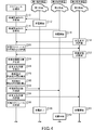
- FIG. 4 is a diagram illustrating a general flow of operation of the entire charging system.
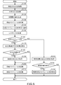
- FIG. 5 is a flowchart illustrating a detailed flow of operations in the schedule management unit.
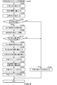
- FIG. 6 is a flowchart illustrating the flow of the special charging schedule creation process.
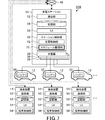
- FIG. 7 is a schematic view showing the configuration of the charging system according to the second embodiment.
- FIG. 1 is a schematic view showing the configuration of the charging system 1 according to the first embodiment.
- the charging system 1 includes a charging station 10, a vehicle 12, a terminal device 14, and an upper unit 16.
- a charging station is exemplified for convenience of explanation.
- the number of charging stations is not limited to one, and may be two or more.
- the vehicle 12 is an electric vehicle or a hybrid vehicle equipped with a battery 20 that supplies electric power to a drive source.
- the vehicle 12 such as an electric vehicle or a hybrid vehicle may be referred to as an EV.
- three vehicles 12 are exemplified.
- the number of vehicles 12 is not limited to three, and a plurality of vehicles may be sufficient, and may be two or four or more.
- a plurality of chargers 30 are installed in the charging station 10.
- three chargers 30 are exemplified.
- the number of the chargers 30 is not limited to three, and a plurality of chargers 30 may be sufficient, may be two, or may be four or more.
- the charger 30 is connected to, for example, a power system (not shown).
- the charger 30 can convert the electric power of the electric power system and supply it to the battery 20 of the vehicle 12. That is, the charging station 10 is a so-called EV power station, and can charge the battery 20 of the vehicle 12.
- the charging of the battery 20 of the vehicle 12 may be abbreviated as the charging of the vehicle 12.
- the charging station 10 includes a communication unit 32, a storage unit 34, a user interface 36, and a station control unit 38 in addition to the charger 30.
- the user interface 36 is abbreviated as UI.
- the communication unit 32 is connected to the communication network 40 by wire or wirelessly.
- the communication unit 32 can establish communication with the host unit 16 and communication with the terminal device 14 through the communication network 40.
- the storage unit 34 is composed of, for example, a non-volatile storage device.
- the storage unit 34 stores, for example, various types of information used in the charging station 10.
- the user interface 36 has an input function such as a touch panel.
- the input function accepts an input operation of a user (for example, the driver of the vehicle 12).
- the user interface 36 has an output function such as a display.
- the output function presents various information to the user.
- the station control unit 38 is composed of a semiconductor integrated circuit including a central processing unit (CPU), a ROM in which programs and the like are stored, and a RAM as a work area.
- the station control unit 38 functions as a charge control unit 42 by executing a program.
- a charging schedule is created, which will be described later.
- Various information regarding the charging of the vehicle 12 by the charger 30 is defined in the charging schedule.
- Various information regarding charging includes, for example, charging start time (scheduled charging start time), charging end time (scheduled charging end time), charging time, charging electric energy, vehicle identifier identifying vehicle 12, and usage status of charger 30.
- the reservation status of the charger 30 and the like are included.
- the charge control unit 42 controls charging of the battery 20 by the charger 30 according to the created charging schedule. For example, the charge control unit 42 causes the charger 30 to start supplying electric power to the vehicle 12 when the current time reaches a predetermined charge start time of the vehicle 12. Further, the charge control unit 42 terminates the supply of electric power to the vehicle 12 to the charger 30 when the current time reaches a predetermined charge end time of the vehicle 12.
- the charge control unit 42 will be described in detail later.
- the terminal device 14 is a portable communication device such as a smartphone or a tablet.
- three terminal devices 14 are exemplified.
- the number of the terminal devices 14 is not limited to three, and a plurality of terminals may be sufficient, and may be two or four or more.
- the number of terminal devices 14 is the same as the number of vehicles 12.
- the terminal device 14 is carried by the driver of the vehicle 12. That is, each of the terminal devices 14 and each of the vehicles 12 correspond individually.
- the terminal device 14 includes a communication unit 50, a storage unit 52, a user interface 54, and a terminal control unit 56.
- the user interface 54 is abbreviated as UI.
- the communication unit 50 is connected to the communication network 40 by wire or wirelessly.
- the communication unit 50 can establish communication with the host unit 16 and communication with the charging station 10 through the communication network 40.
- the terminal device 14 may be able to communicate with the vehicle 12 corresponding to the own device (the vehicle 12 driven by the driver carrying the own device).
- the storage unit 52 is composed of, for example, a non-volatile storage device.
- the storage unit 52 stores, for example, various types of information used in the terminal device 14.
- the user interface 54 has an input function such as a touch panel.
- the input function accepts an input operation of a user (such as a driver of a vehicle 12).
- the user interface 54 has an output function such as a display.
- the output function presents various information to the user.
- the terminal control unit 56 is composed of a semiconductor integrated circuit including a central processing unit (CPU), a ROM in which a program or the like is stored, a RAM as a work area, and the like.
- the terminal control unit 56 controls the entire terminal device 14 by executing a program.
- the upper unit 16 is installed by, for example, a business operator that provides services such as management or information processing related to the charging station 10.
- the upper unit 16 includes a communication unit 60, a storage unit 62, and an upper control unit 64.
- the communication unit 60 is connected to the communication network 40 by wire or wirelessly.
- the communication unit 60 can establish communication with the charging station 10 and communication with the terminal device 14 through the communication network 40.
- the storage unit 62 is composed of, for example, a non-volatile storage device. For example, various information used in the upper unit 16 is stored in the storage unit 62.
- the upper control unit 64 is composed of a semiconductor integrated circuit including a central processing unit (CPU), a ROM in which programs and the like are stored, and a RAM as a work area.
- the upper control unit 64 functions as the schedule management unit 70 by executing the program.
- the schedule management unit 70 creates a charging schedule using the charger 30 at the charging station 10.
- the schedule management unit 70 updates the charging schedule each time a new charging request (charging reservation) is received from the terminal device 14 (in other words, the vehicle 12).
- the schedule management unit 70 transmits the created charging schedule to the charging station 10.
- the charge control unit 42 of the charging station 10 charges the vehicle 12 by the charger 30 based on the received charging schedule.
- the schedule management unit 70 will be described in detail later.
- FIG. 2 is a diagram illustrating an outline of the operation of the schedule management unit 70.
- FIG. 2 illustrates three vehicles 12: a first vehicle, a second vehicle, and a third vehicle.
- the time T10 is the current time. It is assumed that the first vehicle and the second vehicle are currently being charged at the charging station 10.
- the black-painted triangle 80 indicates the charging start time.
- the white triangle 82 indicates the scheduled charging end time.
- the time T11 is the scheduled charging end time of the first vehicle
- the time T12 is the charging end time of the second vehicle.
- the hatched square 84 indicates the amount of charged electric power that has been charged.
- the white square 86 indicates the remaining (uncharged) charging power amount from the current time to the scheduled charging end time. In this situation, it is assumed that the third vehicle makes a new request for charging.
- the hatching triangle 88 indicates the scheduled charging start time.
- the schedule management unit 70 creates a charging schedule on condition that the power consumption in the charging station 10 is less than the contracted power.
- the scheduled charging start time of the third vehicle is determined to be earlier than the current time, for example, time T13.
- the scheduled charging end time of the third vehicle is, for example, time T14.
- the driver of the third vehicle may want to finish charging earlier than the time T14, even if the charging fee is increased.
- the newly charged vehicle 12 (third vehicle) is required to charge the upper unit 16 at an early stage (hereinafter, may be referred to as early charging).
- the schedule management unit 70 sets the scheduled charging start time of the vehicle 12 earlier than the initial scheduled charging start time. For example, as shown by the broken line square 90 in FIG. 2, the scheduled charging start time of the third vehicle is advanced from the time T13 to the time T10 (current time). Then, the scheduled charging end time of the third vehicle can be advanced from the time T14 to the time T15.
- the power consumption in the charging station 10 may exceed the contracted power.
- the schedule management unit 70 realizes early charging in the third vehicle by allocating a part or all of the future charging power amount to be allocated to the first vehicle and the second vehicle currently being charged to the third vehicle. do.
- FIG. 3 is a diagram illustrating an example for realizing early charging.
- the first vehicle and the second vehicle are charging at the current time (time T10), and the third vehicle newly requests early charging.
- the planned SOC which is the SOC (State Of Charge) of the battery 20 at the end of charging, is set in advance before the start of charging. For example, in the case of full charge, the planned SOC is set to 100%.
- the schedule management unit 70 has obtained confirmation of the intention to affirm the SOC reduction permission from the drivers of the first vehicle and the second vehicle.
- the schedule management unit 70 obtains information on the reduction allowable SOC from the drivers of the first vehicle and the second vehicle.
- the allowable reduction SOC is indicated by the amount of reduction based on the planned SOC, for example, allowing a maximum reduction of 30%. Further, the allowable reduction SOC may be indicated by the SOC itself at the end of charging, for example, if the SOC at the end of charging is 70% or more, it is allowed.
- the SOC reduction permit and the reduction permissible SOC are acquired through the terminal device 14 carried by the driver of each of the first vehicle and the second vehicle.
- the SOC reduction permit and the reduction permissible SOC may be obtained directly from each of the first vehicle and the second vehicle.
- the schedule management unit 70 advances the scheduled charging end time of the first vehicle from the initial time T11 to the current time (time T10).
- the schedule management unit 70 allocates the surplus charging electric energy for the first vehicle to the charging for the third vehicle.
- the third vehicle can be charged from the current time (T10) to the time T11.
- the SOC at the current time is 40%.
- the amount of charging power from the time T11 to the time T13 is insufficient. It is assumed that this shortage is less than the charge power amount of the margin (SOC 30%) in the second vehicle (for example, the charge power amount corresponding to the SOC 20%).
- charging in the second vehicle is temporarily suspended from time T11 to time T13. Specifically, at the time T11 indicated by the cross-hatching triangle 96a, the power supply to the second vehicle is temporarily stopped. After that, at the time T13 indicated by the cross-hatching triangle 96b, the power supply to the second vehicle is restarted. As a result, as shown by the cross-hatching square 94 in FIG. 3, a margin for the amount of charging power is generated in the second vehicle. As shown by the arrow A12 in FIG. 3, the schedule management unit 70 allocates the amount of charging power for the second vehicle for the future margin to the charging for the time from the time T11 to the time T13 of the third vehicle. As a result, the third vehicle can be charged in the time from time T11 to time T13.
- the third vehicle can secure the amount of charging power up to the time T13, which is the initial scheduled charging start time. This makes it possible to advance the scheduled charging start time of the third vehicle to the current time (time T10). As a result, the scheduled charging end time of the third vehicle can be advanced to the time T15 earlier than the initial scheduled charging end time (time T14).
- the schedule management unit 70 reduces the SOC at the end of charging to less than the planned SOC set before the start of charging for the vehicle 12 currently being charged. That is, the schedule management unit 70 reduces at least a part of the charging power amount that was planned to be allocated to the vehicle currently being charged. At the same time, the schedule management unit 70 allocates the margin of the future charging power amount generated by the reduction of the SOC (charging power amount) to the charging of the vehicle 12 that requires the early start of charging.
- the schedule management unit 70 creates a charging schedule having the above-mentioned contents.
- the charging schedule having the above-mentioned contents may be referred to as a special charging schedule for convenience of explanation.
- FIG. 4 is a diagram illustrating a general flow of operation of the entire charging system 1.
- FIG. 4 illustrates a first vehicle, a second vehicle, and a third vehicle similar to those in FIGS. 2 and 3. Further, FIG. 4 illustrates three terminal devices 14, a first terminal device, a second terminal device, and a third terminal device. Further, in FIG. 4, the first vehicle corresponds to the first terminal device, the second vehicle corresponds to the second terminal device, and the third vehicle corresponds to the third terminal device.
- the schedule management unit 70 acquires the reduction allowable SOC from the first vehicle (C10). After that, the schedule management unit 70 creates the latest charging schedule, and charging of the first vehicle is started according to the charging schedule (C12). Further, when the second vehicle transmits the charging request to the schedule management unit 70, the schedule management unit 70 acquires the reduction allowable SOC from the second vehicle (C14). After that, the schedule management unit 70 creates the latest charging schedule, and charging of the second vehicle is started according to the charging schedule (C16).
- the third terminal device While the first vehicle and the second vehicle are charging, the third terminal device (third vehicle) transmits a charging request to the schedule management unit 70 for new charging (C18).
- the schedule management unit 70 creates a new charging schedule including charging of the third vehicle in consideration of the current charging schedule, and transmits it to the third terminal device (third vehicle) (C20).
- the driver of the third vehicle is not satisfied with the presented charging schedule, and requests the schedule management unit 70 to start charging early through the third terminal device (third vehicle) (C22).
- the charging system 1 a person who requests an early start of charging (for example, a driver of a third vehicle) is asked to pay an additional fee for early charging in addition to the charging fee for normal charging. And. That is, the vehicle 12 (terminal device 14) that requests the early start of charging is required to pay the consideration necessary for obtaining the merit of the early start of charging.
- This necessary consideration shall be monetary, for example, an increase (increase) in the charging fee.
- the necessary payment of consideration is not limited to monetary payment and can be set as appropriate.
- the necessary consideration to be paid may be referred to as the necessary consideration.
- the charging system 1 those who cooperate in reducing the amount of charging power in the future (for example, the driver of the first vehicle and the driver of the second vehicle) are asked to receive the consideration for the cooperation. And. That is, the vehicle 12 (terminal device 14) whose future charging power amount is reduced is presented with the receipt of consideration to compensate for the demerit due to the reduction of the charging power amount.
- the compensation for this compensation shall be monetary, for example, a discount (reduction) of the charging fee.
- the compensation to be compensated is not limited to monetary ones and can be set as appropriate.
- the consideration to be compensated may be referred to as the compensation receipt consideration.
- the special charging schedule can be smoothly realized by giving the cooperator the compensation receipt consideration and obliging the requester of the early charge the necessary payment consideration.
- the schedule management unit 70 Upon receiving the request for early charging, the schedule management unit 70 derives the amount of early charging power for the third vehicle (C24).
- the amount of early charge power indicates the amount of charge power for moving forward. More specifically, the early charging electric energy indicates the charging electric energy between the current time of the vehicle requesting the early charging (third vehicle) and the initial scheduled charging start time.
- the schedule management unit 70 derives the required payment consideration based on the amount of early charging power (C26). For example, the schedule management unit 70 may gradually increase the required payment consideration as the amount of early charging power increases.
- the schedule management unit 70 derives the amount of reduced power consumption for each vehicle 12 (hereinafter, may be referred to as a vehicle subject to reduction) in which the SOC is reduced at the end of charging (C28).
- the schedule management unit 70 derives the reduced electric energy for each vehicle 12 by referring to, for example, the allowable reduction SOC for each vehicle 12, the early charging electric energy amount, and the current charging schedule.
- the reduced power amount indicates the amount of charging power to be reduced among the amount of charging power planned in the future in the vehicle to be reduced.
- the schedule management unit 70 derives the compensation / receipt consideration for each vehicle 12 based on the amount of reduced power consumption for each vehicle 12 (C30). For example, the schedule management unit 70 may gradually increase the compensation receipt consideration as the amount of reduced power consumption increases.
- the schedule management unit 70 transmits the derived compensation receipt consideration to the first vehicle and the second vehicle (C32), and transmits the derived necessary payment consideration to the third vehicle (C34). Then, the schedule management unit 70 updates the charging schedule (C36). Then, the charging of the first vehicle is completed earlier than the initial scheduled charging end time (C38). Along with this, charging of the third vehicle is started earlier than the initial scheduled charging start time (C40). Further, when the initial scheduled charging end time of the first vehicle is reached, the charging of the second vehicle is temporarily interrupted (C42). At this time, charging of the third vehicle is continued. As a result, charging of the third vehicle is completed earlier than the initial charging end time.
- FIG. 5 is a flowchart illustrating a detailed flow of operations in the schedule management unit 70.
- the driver makes a charging request (charging reservation) for the vehicle 12 via the user interface 54 of the terminal device 14.
- the schedule management unit 70 starts a series of processes shown in FIG.
- the terminal device 14 and the vehicle 12 that are the request source of the charge request may be referred to as the request source terminal device and the request source vehicle.
- the schedule management unit 70 acquires the current SOC of the battery 20 in the requesting vehicle (S100). For example, the schedule management unit 70 acquires the current SOC of the requesting vehicle through the requesting terminal device.
- the schedule management unit 70 may specify the requesting vehicle from the requesting terminal device and directly acquire the current SOC from the specified requesting vehicle.
- the schedule management unit 70 acquires the scheduled SOC desired by the driver through the requesting terminal device (S110). For example, if a full charge is desired, the planned SOC is set to 100%. Next, the schedule management unit 70 derives the amount of charging power required from the current SOC to the planned SOC (S120).
- the schedule management unit 70 creates a charging schedule based on the derived charging electric energy (S130).
- the schedule management unit 70 creates a new charging schedule on the assumption that the requesting vehicle is newly charged in consideration of the current charging schedule status.
- the new charging schedule includes the scheduled charging start time and the scheduled charging end time of the requesting vehicle.
- the schedule management unit 70 transmits the derived new charging schedule to the requesting terminal device (S140).
- the requesting terminal device receives the charging schedule including the scheduled charging start time and the charging end time as a result of the charging request.
- the requesting terminal device presents the charging schedule (scheduled charging start time and scheduled charging end time) to the driver through the user interface 54.
- the driver inputs, through the user interface 54, whether or not to accept the presented charging schedule.
- the requesting terminal device transmits the input result of whether or not to approve the charging schedule as a response to the upper unit 16 through the communication unit 50.
- the schedule management unit 70 acquires the response from the requesting terminal device (S150).
- the schedule management unit 70 determines whether or not the content of the response approves the charging schedule (S160).
- the schedule management unit 70 acquires the presence or absence of the SOC reduction permission (S170). For example, the schedule management unit 70 inquires of the requesting terminal device whether or not the SOC reduction permission is available. The requesting terminal device prompts the driver to input whether or not the SOC reduction permission is present, and transmits the input result to the schedule management unit 70. The presence or absence of the SOC reduction permission is stored in association with the requesting vehicle.
- the schedule management unit 70 acquires the reduction allowable SOC (S190). For example, the schedule management unit 70 inquires of the requesting terminal device for the reduction allowable SOC. The requesting terminal device prompts the driver to input the reduction allowable SOC, and transmits the input result to the schedule management unit 70. On the other hand, when the SOC reduction permission is denied (NO in S180), the schedule management unit 70 does not perform the process of step S190.
- the schedule management unit 70 transmits the charging schedule created in step S130 to the charging station 10 (S200). Then, the schedule management unit 70 updates the created charging schedule to the latest charging schedule (S210), and ends a series of processes. Further, the charging station 10 that has received the charging schedule updates the received charging schedule to the latest charging schedule. As a result, charging is performed according to the latest charging schedule.
- step S160 when the content of the response does not approve the charging schedule (NO in S160), the schedule management unit 70 acquires whether or not there is a request for early charging. For example, the schedule management unit 70 inquires of the requesting terminal device whether or not there is a request for early charging. The requesting terminal device prompts the driver to input whether or not there is a request for early charging, and transmits the input result to the schedule management unit 70.
- the schedule management unit 70 When early charging is requested (YES in S230), the schedule management unit 70 performs a special charging schedule creation process (S240) and ends a series of processes.
- the special charging schedule creation process will be described in detail later.
- the schedule management unit 70 ends a series of processes without performing step S240. In this case, the charging schedule created in step S130 is discarded and the current charging schedule is maintained.
- FIG. 6 is a flowchart illustrating the flow of the special charging schedule creation process.
- the schedule management unit 70 acquires the allowable payment consideration from the requesting terminal device (S300).
- the permissible payment consideration indicates the maximum value of the consideration that the driver can tolerate in order to obtain the benefit of the early start of charging.
- the schedule management unit 70 inquires of the requesting terminal device for the allowable payment consideration.
- the requesting terminal device prompts the driver to input the allowable payment consideration, and transmits the input result to the schedule management unit 70.
- the schedule management unit 70 refers to the charging schedule (initial charging schedule) derived in step S130, subtracts the current time from the scheduled charging start time of the requesting vehicle, and derives the advance time. Then, the schedule management unit 70 derives the early charge electric energy amount based on the advance time (S310). Next, the schedule management unit 70 derives the required payment consideration based on the amount of early charging power (S320).
- the schedule management unit 70 determines whether or not the amount of allowable payment consideration (absolute value) is equal to or greater than the required payment consideration amount (absolute value) (S330). When the allowable payment consideration is less than the required payment consideration (NO in S330), the schedule management unit 70 transmits to the requesting terminal device that early charging is not possible (S340), and ends a series of processing.
- the schedule management unit 70 extracts the SOC reduction permitted vehicle for the vehicle 12 currently being charged (S350). Next, the schedule management unit 70 totals the reduction allowable SOCs of each of the extracted SOC reduction permitted vehicles to derive the total reduction permitted electric energy (S360).
- the schedule management unit 70 determines whether or not the total reduced permitted electric energy is equal to or greater than the early charging electric energy (S370). When the total reduction permitted electric energy is less than the early charge electric energy (NO in S370), the schedule management unit 70 transmits to the requesting terminal device that early charge is impossible (S340), and ends a series of processes.
- the schedule management unit 70 determines the vehicle subject to SOC reduction (S380). Specifically, the schedule management unit 70 determines the SOC reduction target vehicle from the extracted SOC reduction permitted vehicles according to a predetermined priority.
- the predetermined priority is, for example, the order in which the scheduled charging end time is closer to the present.
- the predetermined priority is not limited to this example, and can be arbitrarily set.
- the schedule management unit 70 adds the reduction allowable SOCs in order from the SOC reduction permitted vehicle having the highest priority, and the SOC reduction target up to the SOC reduction permitted vehicle when the added value becomes equal to or more than the early charging power amount. It is a vehicle.
- the schedule management unit 70 derives the reduced power consumption for each SOC reduction target vehicle based on the reduction allowable SOC (S390). Next, the schedule management unit 70 derives the compensation receipt consideration for each SOC reduction target vehicle based on the reduced power consumption for each SOC reduction target vehicle (S400).
- the schedule management unit 70 reduces the SOC at the end of charging for each of the vehicles subject to SOC reduction based on the amount of reduced power, and has a charging schedule (special charging schedule) that advances the scheduled charging start time of the requesting vehicle. ) Is created (S410).
- the schedule management unit 70 transmits information on the compensation receipt consideration derived in step S400 to each of the terminal devices 14 corresponding to the vehicles subject to SOC reduction (S420).
- the terminal device 14 corresponding to the vehicle subject to SOC reduction presents the received compensation / receipt consideration information to the driver through the user interface 54.
- the schedule management unit 70 transmits the information of the required payment consideration derived in step S320 to the requesting terminal device (S420).
- the requesting terminal device presents the received required payment consideration information to the driver through the user interface 54.
- the schedule management unit 70 transmits the charging schedule (special charging schedule) created in step S410 to the charging station 10 (S430). Then, the schedule management unit 70 updates the charging schedule to the charging schedule created in step S410 (S440), and ends a series of processes. Further, the charging station 10 that has received the charging schedule updates the charging schedule to the received charging schedule. As a result, the scheduled charging start time of the requesting vehicle is advanced compared to the initial charging schedule.
- the schedule management unit 70 of the charging system 1 of the first embodiment reduces at least a part of the future charging power amount planned to be allocated to the vehicle 12 currently being charged, and starts charging at an early stage. Create a charging schedule for charging the requested vehicle 12.
- the charging of the vehicle 12 can be terminated at an early stage while suppressing the increase in the power consumption in the charging station 10.
- the schedule management unit 70 of the charging system 1 of the first embodiment requests the necessary payment consideration for the vehicle 12 that requests the early start of charging, and receives compensation for the vehicle 12 whose future charging power amount is reduced. Present the consideration.
- the charging system 1 of the first embodiment it is possible to suppress the complaints of both the vehicle 12 that requires the early start of charging and the vehicle 12 that reduces the amount of charging power in the future.
- the charging system 1 of the first embodiment it is possible to smoothly accommodate the charging power amount between the vehicle 12 that requires the early start of charging and the vehicle 12 that reduces the charging power amount in the future. can.
- the schedule management unit 70 of the upper unit 16 creates the charging schedule of one charging station 10 in parallel.
- the schedule management unit 70 of the upper unit 16 may guide the newly charged vehicle 12 to the charging station 10 with less congestion. As a result, it is possible to prevent a large number of requests for early charging from being unnecessarily generated.
- the schedule management unit 70 has acquired the reduction allowable SOC from the SOC reduction permitted vehicle.
- the schedule management unit 70 may acquire not only the reduction allowable SOC but also the lower limit value (requested receiving consideration) of the consideration requested by the driver when the charging power amount is reduced, for example.
- the schedule management unit 70 SOCs the SOC reduction permitted vehicle only when the condition of the reduction allowable SOC is satisfied and the amount of consideration obtained (absolute value) is equal to or larger than the amount of the requested receipt consideration (absolute value). It may be a vehicle to be reduced.
- the schedule management unit 70 is provided in the upper unit 16.
- the schedule management unit 70 is not limited to the mode provided in the upper unit 16.
- FIG. 7 is a schematic diagram showing the configuration of the charging system 200 according to the second embodiment.
- a schedule management unit 70 is provided in the charging station 10.
- the station control unit 38 of the second embodiment functions as a charge control unit 42 and also as a schedule management unit 70 by executing a program.
- the upper unit 16 may not be installed.
- the schedule management unit 70 of the second embodiment can create a charging schedule (special charging schedule) having the same contents as that of the first embodiment provided in the upper unit 16.
- the charging station 10 of the second embodiment can end the charging of the vehicle 12 at an early stage while suppressing an increase in the power consumption of the charging station 10 as in the first embodiment.
- the schedule management unit 70 of the second embodiment requests the necessary payment consideration for the vehicle 12 that requests the early start of charging, and the vehicle 12 whose future charging power amount is reduced. May present compensation receipt consideration.
- the charging request is made via the user interface 54 of the terminal device 14.
- the charging request may be made via the user interface 36 of the charging station 10.
- the charging request may be made via an in-vehicle device such as a navigation device of the vehicle 12.
- the special charging schedule was automatically applied after the compensation receipt consideration was presented to the vehicle subject to SOC reduction. This is because the intention to allow the reduction of SOC was shown in advance before the start of charging.
- the schedule management unit 70 may reconfirm the intention to permit the reduction of the SOC when the compensation receipt consideration is presented to the vehicle subject to the SOC reduction.
- the driver of the vehicle subject to SOC reduction compares the SOC at the end of charging with the compensation receipt consideration and reconsiders whether or not to cooperate in the future reduction of the charging power amount. Can be done.
- the SOC reduction target vehicle may be re-determined.
- Charging system 10 Charging station 12: Vehicle 16: Upper unit 20: Battery 30: Charger 42: Charge control unit 70: Schedule management unit
Landscapes
- Engineering & Computer Science (AREA)
- Business, Economics & Management (AREA)
- Power Engineering (AREA)
- Strategic Management (AREA)
- Finance (AREA)
- Development Economics (AREA)
- Accounting & Taxation (AREA)
- Economics (AREA)
- Transportation (AREA)
- Mechanical Engineering (AREA)
- Theoretical Computer Science (AREA)
- Marketing (AREA)
- Physics & Mathematics (AREA)
- General Business, Economics & Management (AREA)
- General Physics & Mathematics (AREA)
- Entrepreneurship & Innovation (AREA)
- Health & Medical Sciences (AREA)
- Game Theory and Decision Science (AREA)
- Tourism & Hospitality (AREA)
- Primary Health Care (AREA)
- Human Resources & Organizations (AREA)
- General Health & Medical Sciences (AREA)
- Water Supply & Treatment (AREA)
- Public Health (AREA)
- Data Mining & Analysis (AREA)
- Life Sciences & Earth Sciences (AREA)
- Sustainable Development (AREA)
- Sustainable Energy (AREA)
- Charge And Discharge Circuits For Batteries Or The Like (AREA)
- Electric Propulsion And Braking For Vehicles (AREA)
- Remote Monitoring And Control Of Power-Distribution Networks (AREA)
Abstract
充電システム1は、1または複数の充電ステーション10と、充電ステーション10と通信可能な上位ユニット16と、を備え、充電ステーション10は、車両12に搭載されたバッテリ20を充電可能な複数の充電器30と、充電スケジュールに従って充電器30による充電を制御する充電制御部42と、を有し、上位ユニット16は、充電スケジュールを作成するスケジュール管理部70を有し、スケジュール管理部70は、現在充電中の車両12に充てる予定であった将来の充電電力量の少なくとも一部を削減し、早期の充電開始を要求する車両12についての充電に充てる充電スケジュールを作成する。
Description
本開示は、車両のバッテリの充電が可能な充電システムおよび充電ステーションに関する。本出願は2020年6月29日に提出された日本特許出願第2020-111320号に基づく優先権の利益を主張するものであり、その内容は本出願に援用される。
例えば、特許文献1には、所定の充電行為が充電スケジュールに登録されていない場合、EV管理センターがその旨を車載器に通知することが開示されている。
充電ステーションでは、一般的には、充電の要求があった車両から順番に充電が開始される。このため、新たに充電の要求が行われるタイミングによっては、充電の開始が遅くなり、運転者の望む時間内に充電が終了しない事態が起こり得る。
本開示は、早期に充電を終了させることが可能な充電システムおよび充電ステーションを提供することを目的としている。
上記課題を解決するために、本開示の一態様に係る充電システムは、1または複数の充電ステーションと、充電ステーションと通信可能な上位ユニットと、を備え、充電ステーションは、車両に搭載されたバッテリを充電可能な複数の充電器と、充電スケジュールに従って充電器による充電を制御する充電制御部と、を有し、上位ユニットは、充電スケジュールを作成するスケジュール管理部を有し、スケジュール管理部は、現在充電中の車両に充てる予定であった将来の充電電力量の少なくとも一部を削減し、早期の充電開始を要求する車両についての充電に充てる充電スケジュールを作成する。
また、スケジュール管理部は、早期の充電開始を要求する車両には、早期の充電開始によるメリットを得るために必要な対価の支払いを要求し、将来の充電電力量が削減される車両には、充電電力量の削減によるデメリットを補填する対価の受け取りを提示するとしてもよい。
上記課題を解決するために、本開示の一態様に係る充電ステーションは、車両に搭載されたバッテリを充電可能な複数の充電器と、充電スケジュールに従って充電器による充電を制御する充電制御部と、充電スケジュールを作成するスケジュール管理部と、を備え、スケジュール管理部は、現在充電中の車両に充てる予定であった将来の充電電力量の少なくとも一部を削減し、早期の充電開始を要求する車両についての充電に充てる充電スケジュールを作成する。
本開示によれば、早期に充電を終了させることが可能となる。
以下に添付図面を参照しながら、本開示の実施形態について詳細に説明する。かかる実施形態に示す寸法、材料、その他具体的な数値等は、理解を容易とするための例示にすぎず、特に断る場合を除き、本開示を限定するものではない。なお、本明細書および図面において、実質的に同一の機能、構成を有する要素については、同一の符号を付することにより重複説明を省略し、また本開示に直接関係のない要素は図示を省略する。
(第1実施形態)
図1は、第1実施形態に係る充電システム1の構成を示す概略図である。充電システム1は、充電ステーション10、車両12、端末装置14および上位ユニット16を含む。図1の例では、説明の便宜のため1個の充電ステーションが例示されている。なお、充電ステーションの数は、1個に限らず、2個以上の複数であってもよい。
図1は、第1実施形態に係る充電システム1の構成を示す概略図である。充電システム1は、充電ステーション10、車両12、端末装置14および上位ユニット16を含む。図1の例では、説明の便宜のため1個の充電ステーションが例示されている。なお、充電ステーションの数は、1個に限らず、2個以上の複数であってもよい。
車両12は、駆動源に電力を供給するバッテリ20を搭載している電気自動車またはハイブリッド自動車などである。以後、電気自動車またはハイブリッド自動車などの車両12を、EVと呼ぶ場合がある。図1の例では、3台の車両12が例示されている。しかし、車両12の数は、3台に限らず、複数あれば足り、2台でもよいし、4台以上でもよい。
充電ステーション10には、複数の充電器30が設置されている。図1の例では、3個の充電器30が例示されている。しかし、充電器30の数は、3個に限らず、複数あれば足り、2個でもよいし、4個以上でもよい。充電器30は、例えば、不図示の電力系統に接続される。充電器30は、電力系統の電力を変換して車両12のバッテリ20に供給することができる。すなわち、充電ステーション10は、所謂、EVパワーステーションであり、車両12のバッテリ20を充電可能となっている。以後、車両12のバッテリ20の充電を、車両12の充電と略記する場合がある。
充電ステーション10は、充電器30の他に、通信部32、記憶部34、ユーザインターフェース36およびステーション制御部38を含む。なお、図1では、ユーザインターフェース36をUIと略記している。
通信部32は、有線または無線によって通信ネットワーク40に接続される。通信部32は、通信ネットワーク40を通じて、上位ユニット16との間の通信および端末装置14との間の通信を確立することができる。記憶部34は、例えば、不揮発性の記憶装置で構成される。記憶部34には、例えば、充電ステーション10内で利用される各種の情報が記憶される。ユーザインターフェース36は、例えば、タッチパネルなどの入力機能を有する。入力機能は、ユーザ(例えば、車両12の運転者)の入力操作を受け付ける。また、ユーザインターフェース36は、例えば、ディスプレイなどの出力機能を有する。出力機能は、ユーザに各種の情報を提示する。
ステーション制御部38は、中央処理装置(CPU)、プログラム等が格納されたROM、ワークエリアとしてのRAM等を含む半導体集積回路から構成される。ステーション制御部38は、プログラムを実行することで、充電制御部42として機能する。
充電システム1では、後述するが、充電スケジュールが作成される。充電スケジュールには、充電器30による車両12の充電に関する各種の情報が定義されている。充電に関する各種の情報は、例えば、充電開始時刻(充電開始予定時刻)、充電終了時刻(充電終了予定時刻)、充電時間、充電電力量、車両12を識別する車両識別子、充電器30の使用状況または充電器30の予約状況などが含まれる。
充電制御部42は、作成された充電スケジュールに従って充電器30によるバッテリ20の充電を制御する。例えば、充電制御部42は、現在時刻が、予め定められた車両12の充電開始時刻となると、充電器30に車両12への電力の供給を開始させる。また、充電制御部42は、現在時刻が、予め定められた車両12の充電終了時刻となると、充電器30に車両12への電力の供給を終了させる。充電制御部42については、後に詳述する。
端末装置14は、例えば、スマートフォンまたはタブレットなどの持ち運び可能な通信機器である。図1の例では、3台の端末装置14が例示されている。しかし、端末装置14の数は、3台に限らず、複数あれば足り、2台でもよいし、4台以上でもよい。例えば、端末装置14の数は、車両12の数と同じである。具体的には、端末装置14は、車両12の運転者によって携帯されている。つまり、端末装置14の各々と、車両12の各々とが、個別に対応している。
端末装置14は、通信部50、記憶部52、ユーザインターフェース54および端末制御部56を含む。なお、図1では、ユーザインターフェース54をUIと略記している。
通信部50は、有線または無線によって通信ネットワーク40に接続される。通信部50は、通信ネットワーク40を通じて、上位ユニット16との間の通信および充電ステーション10との間の通信を確立することができる。なお、端末装置14は、自装置に対応する車両12(自装置を携帯する運転者が運転する車両12)と通信可能であってもよい。
記憶部52は、例えば、不揮発性の記憶装置で構成される。記憶部52には、例えば、端末装置14内で利用される各種の情報が記憶される。ユーザインターフェース54は、例えば、タッチパネルなどの入力機能を有する。入力機能は、ユーザ(車両12の運転者など)の入力操作を受け付ける。また、ユーザインターフェース54は、例えば、ディスプレイなどの出力機能を有する。出力機能は、ユーザに各種の情報を提示する。
端末制御部56は、中央処理装置(CPU)、プログラム等が格納されたROM、ワークエリアとしてのRAM等を含む半導体集積回路から構成される。端末制御部56は、プログラムを実行することで端末装置14全体を制御する。
上位ユニット16は、例えば、充電ステーション10に関する管理または情報処理などのサービスを提供する事業者によって設置される。上位ユニット16は、通信部60、記憶部62および上位制御部64を含む。
通信部60は、有線または無線によって通信ネットワーク40に接続される。通信部60は、通信ネットワーク40を通じて、充電ステーション10との間の通信および端末装置14との間の通信を確立することができる。記憶部62は、例えば、不揮発性の記憶装置で構成される。記憶部62には、例えば、上位ユニット16内で利用される各種の情報が記憶される。
上位制御部64は、中央処理装置(CPU)、プログラム等が格納されたROM、ワークエリアとしてのRAM等を含む半導体集積回路から構成される。上位制御部64は、プログラムを実行することで、スケジュール管理部70として機能する。
スケジュール管理部70は、充電ステーション10における充電器30を用いた充電スケジュールを作成する。スケジュール管理部70は、端末装置14(換言すると、車両12)から新たに充電の要求(充電の予約)を受ける都度、充電スケジュールを更新する。スケジュール管理部70は、作成した充電スケジュールを充電ステーション10に送信する。充電ステーション10の充電制御部42は、受信した充電スケジュールに基づいて充電器30による車両12の充電を行う。スケジュール管理部70については、後に詳述する。
図2は、スケジュール管理部70の動作の概要を説明する図である。図2では、第1車両、第2車両および第3車両という3台の車両12を例示している。また、図2では、時刻T10が現在時刻であるとする。第1車両および第2車両は、充電ステーション10において現在充電中であるとする。図2において、黒塗り三角80は、充電開始時刻を示す。白抜き三角82は充電終了予定時刻を示す。例えば、時刻T11が第1車両の充電終了予定時刻であり、時刻T12が第2車両の充電終了時刻である。ハッチング四角84は、充電済の充電電力量を示している。白抜き四角86は、現在時刻から充電終了予定時刻までの残りの(未充電の)充電電力量を示している。この状況において、第3車両が新たに充電の要求を行ったとする。図2において、ハッチング三角88は、充電開始予定時刻を示す。
例えば、第3車両の充電を直ぐに開始すると、充電ステーション10内の消費電力が契約電力を超えるおそれがあるとする。この場合、スケジュール管理部70は、充電ステーション10内の消費電力が契約電力未満となることを条件として充電スケジュールを作成する。これにより、第3車両の充電開始予定時刻は、現在時刻より先の、例えば、時刻T13に決められる。そうすると、第3車両の充電終了予定時刻は、例えば、時刻T14となる。
しかし、第3車両の運転者は、充電料金が割り増しになってでも、時刻T14よりも早期に充電を終了させたいと望むことがある。
そこで、このような場合、新たに充電される車両12(第3車両)は、早期に充電を行うこと(以後、早期充電と呼ぶ場合がある。)を上位ユニット16に要求する。そして、スケジュール管理部70は、新たに充電される車両12から早期充電の要求があると、その車両12の充電開始予定時刻を当初の充電開始予定時刻よりも早めるようにする。例えば、図2の破線四角90で示すように、第3車両の充電開始予定時刻を時刻T13から時刻T10(現在時刻)に早める。そうすると、第3車両の充電終了予定時刻を時刻T14から時刻T15に早めることができる。
しかし、第3車両の充電開始予定時刻を単純に早めるだけだと、充電ステーション10内の消費電力が契約電力を超えるおそれがある。
そこで、スケジュール管理部70は、現在充電中の第1車両および第2車両に充てる予定の将来の充電電力量の一部または全部を第3車両に充てることで、第3車両における早期充電を実現する。
図3は、早期充電を実現するための一例を説明する図である。図3では、現在時刻(時刻T10)において、第1車両および第2車両が充電中であり、第3車両が新たに早期充電を要求したとする。
例えば、充電終了時におけるバッテリ20のSOC(State Of Charge:充電率)である予定SOCが、充電開始前に予め設定される。例えば、満充電の場合、予定SOCが100%に設定される。
ここで、第1車両および第2車両の運転者は、充電終了時のSOCが、充電開始前に設定された予定SOCよりも少なくてもよいことを了承しているとする。以後、充電終了時のSOCが予定SOCよりも少なくても許容できるか否かの指標を、SOC削減許可と呼ぶ場合がある。つまり、スケジュール管理部70は、第1車両および第2車両の運転者から、SOC削減許可を肯定する意思の確認を得ているとする。
また、第1車両および第2車両の運転者は、充電終了時のSOCがどの程度まで少なくてもよいかを明示しているとする。以後、充電終了時のSOCがどの程度まで少なくても許容できるかを示す指標を、削減許容SOCと呼ぶ場合がある。つまり、スケジュール管理部70は、第1車両および第2車両の運転者から、削減許容SOCの情報を得ているとする。
削減許容SOCは、例えば、最大30%の削減を許容するなどのように、予定SOCを基準とした削減量で示される。また、削減許容SOCは、例えば、充電終了時のSOCが70%以上であれば許容するなどのように、充電終了時のSOC自体で示されてもよい。
また、SOC削減許可および削減許容SOCは、第1車両および第2車両の各々の運転者が携帯する端末装置14を通じて取得される。なお、SOC削減許可および削減許容SOCは、第1車両および第2車両の各々から直接的に取得されてもよい。
例えば、第1車両では、予定SOCが100%であり、SOCが70%以上であれば充電の終了を許容できるとし、現在時刻のSOCが80%であったとする。この例では、第1車両の充電を現在時刻において終了することができる。このため、スケジュール管理部70は、図3の白抜き三角82で示すように、第1車両の充電終了予定時刻を当初の時刻T11から現在時刻(時刻T10)に早める。
そうすると、図3のクロスハッチング四角92で示すように、第1車両の充電に充てる予定であった将来の充電電力量の余裕分(SOC20%分=100%-80%)が発生する。スケジュール管理部70は、図3の矢印A10で示すように、第1車両についての余裕分の充電電力量を第3車両についての充電に充てる。これにより、第3車両は、現在時刻(T10)から時刻T11までの時間に充電することができる。
また、第2車両では、予定SOCが100%であり、SOCが70%以上であれば充電の終了を許容できるとし、現在時刻のSOCが40%であるとする。この例では、現在以降に第2車両の充電に充てる予定の充電電力量のうち、最大でSOC30%(100%-70%)の充電電力量の余裕分を発生させることができる。
また、第3車両では、図3のクロスハッチング四角94で示すように、時刻T11から時刻T13までの充電電力量が不足する。この不足分は、第2車両における余裕分(SOC30%分)の充電電力量未満(例えば、SOC20%に相当する充電電力量)であるとする。
そこで、第2車両における充電を時刻T11から時刻T13までの間、一旦中断させる。具体的には、クロスハッチング三角96aで示す時刻T11において、第2車両への電力の供給を一旦停止させるようにする。その後、クロスハッチング三角96bで示す時刻T13において、第2車両への電力の供給を再開させるようにする。これにより、図3のクロスハッチング四角94で示すように、第2車両において充電電力量の余裕分が発生する。スケジュール管理部70は、図3の矢印A12で示すように、第2車両についての将来の余裕分の充電電力量を第3車両の時刻T11から時刻T13までの時間の充電に充てる。これにより、第3車両は、時刻T11から時刻T13までの時間に充電することができる。
このようにして、第3車両は、当初の充電開始予定時刻である時刻T13までの充電電力量を確保することができる。これにより、第3車両の充電開始予定時刻を現在時刻(時刻T10)まで前倒しすることが可能となる。その結果、第3車両の充電終了予定時刻を当初の充電終了予定時刻(時刻T14)よりも早い時刻T15に前倒しすることができる。
すなわち、スケジュール管理部70は、早期充電の要求があった場合、現在充電中の車両12について、充電終了時におけるSOCを充電開始前に設定された予定SOC未満に削減する。つまり、スケジュール管理部70は、現在充電中の車両に充てる予定であった充電電力量の少なくとも一部を削減する。それとともに、スケジュール管理部70は、SOC(充電電力量)の削減によって発生する将来の充電電力量の余裕分を、早期の充電開始を要求する車両12についての充電に充てる。スケジュール管理部70は、上述のような内容の充電スケジュールを作成する。以後、上述のような内容の充電スケジュールを、説明の便宜のため、特殊充電スケジュールと呼ぶ場合がある。
図4は、充電システム1全体の動作の大凡の流れを説明する図である。図4では、図2および図3と同様の第1車両、第2車両および第3車両を例示している。また、図4では、第1端末装置、第2端末装置、第3端末装置という3台の端末装置14を例示している。また、図4では、第1車両と第1端末装置とが対応し、第2車両と第2端末装置とが対応し、第3車両と第3端末装置とが対応している。
第1車両が充電要求をスケジュール管理部70に送信する際、スケジュール管理部70は、第1車両から削減許容SOCを取得する(C10)。その後、スケジュール管理部70が最新の充電スケジュールを作成し、その充電スケジュールに従って第1車両の充電が開始される(C12)。また、第2車両が充電要求をスケジュール管理部70に送信する際、スケジュール管理部70は、第2車両から削減許容SOCを取得する(C14)。その後、スケジュール管理部70は最新の充電スケジュールを作成し、その充電スケジュールに従って第2車両の充電が開始される(C16)。
第1車両および第2車両が充電中において、第3端末装置(第3車両)は、新たに充電を行うべく、充電要求をスケジュール管理部70に送信する(C18)。
スケジュール管理部70は、現在の充電スケジュールを考慮して、第3車両の充電を含む新たな充電スケジュールを作成し、第3端末装置(第3車両)に送信する(C20)。第3車両の運転者は、提示された充電スケジュールでは足りず、第3端末装置(第3車両)を通じてスケジュール管理部70に早期の充電開始を要求する(C22)。
ここで、充電システム1では、早期の充電開始を要求する者(例えば、第3車両の運転者)には、通常の充電による充電料金に加え、早期充電の対価を追加的に支払ってもらうこととする。つまり、早期の充電開始を要求する車両12(端末装置14)には、早期の充電開始によるメリットを得るために必要な対価の支払いを要求する。この必要な対価は、例えば、充電料金の割り増し(増額)などの金銭的なものとする。なお、必要な対価の支払いは、金銭的なものに限らず、適宜設定することができる。以後、支払うべき必要な対価のことを、必要支払対価と呼ぶ場合がある。
これに対し、充電システム1では、将来の充電電力量の削減に協力してくれる者(例えば、第1車両の運転者および第2車両の運転者)には、協力の対価を受け取ってもらうこととする。つまり、将来の充電電力量が削減される車両12(端末装置14)には、充電電力量の削減によるデメリットを補填する対価の受け取りを提示する。この補填する対価は、例えば、充電料金の割り引き(減額)などの金銭的なものとする。なお、補填する対価は、金銭的なものに限らず、適宜設定することができる。以後、補填する対価のことを、補填受取対価と呼ぶ場合がある。
このように、協力者には補填受取対価を与え、早期充電の要求者には必要支払対価を義務付けることで、特殊充電スケジュールを円滑に実現することができる。
スケジュール管理部70は、早期充電の要求を受けると、第3車両についての早期充電電力量を導出する(C24)。早期充電電力量は、前倒しする分の充電電力量を示す。より詳細には、早期充電電力量は、早期充電の要求元車両(第3車両)における現在時刻から当初の充電開始予定時刻までの間の充電電力量を示す。スケジュール管理部70は、早期充電電力量に基づいて必要支払対価を導出する(C26)。例えば、スケジュール管理部70は、早期充電電力量が多くなるに従って必要支払対価を漸増させてもよい。
また、スケジュール管理部70は、充電終了時のSOCの削減が行われる車両12(以後、削減対象車両という場合がある)毎の削減電力量を導出する(C28)。スケジュール管理部70は、例えば、車両12毎の削減許容SOC、早期充電電力量および現在の充電スケジュールを参照して車両12毎の削減電力量を導出する。削減電力量は、削減対象車両における将来予定されていた充電電力量のうち削減される充電電力量を示す。スケジュール管理部70は、車両12毎の削減電力量に基づいて車両12毎の補填受取対価を導出する(C30)。例えば、スケジュール管理部70は、削減電力量が多くなるに従って補填受取対価を漸増させてもよい。
スケジュール管理部70は、導出した補填受取対価を第1車両および第2車両に送信し(C32)、導出した必要支払対価を第3車両に送信する(C34)。そして、スケジュール管理部70は、充電スケジュールを更新する(C36)。そうすると、第1車両の充電は、当初の充電終了予定時刻よりも早く終了される(C38)。それに伴い、第3車両の充電が、当初の充電開始予定時刻よりも早く開始される(C40)。また、第1車両の当初の充電終了予定時刻となると、第2車両の充電が一旦中断される(C42)。このとき、第3車両の充電は継続される。その結果、第3車両の充電が、当初の充電終了時刻よりも早く終了される。
上述の図4では、充電システム1全体の動作の大凡の流れを説明していた。次に、スケジュール管理部70にフォーカスしてスケジュール管理部70の詳細な動作を説明する。
図5は、スケジュール管理部70における動作の詳細な流れを説明するフローチャートである。例えば、運転者は、端末装置14のユーザインターフェース54を介して車両12の充電要求(充電予約)を行う。スケジュール管理部70は、通信ネットワーク40を通じて充電要求を受信すると、図5の一連の処理を開始する。以後、充電要求の要求元の端末装置14および車両12を、要求元端末装置および要求元車両と呼ぶ場合がある。
まず、スケジュール管理部70は、要求元車両におけるバッテリ20の現在のSOCを取得する(S100)。例えば、スケジュール管理部70は、要求元端末装置を通じて要求元車両の現在のSOCを取得する。なお、スケジュール管理部70は、要求元端末装置から要求元車両を特定し、特定した要求元車両から直接的に現在のSOCを取得してもよい。
次に、スケジュール管理部70は、要求元端末装置を通じて、運転者が希望する予定SOCを取得する(S110)。例えば、満充電を希望する場合、予定SOCは100%とされる。次に、スケジュール管理部70は、現在のSOCから予定SOCまでに必要な充電電力量を導出する(S120)。
次に、スケジュール管理部70は、導出した充電電力量に基づいて充電スケジュールを作成する(S130)。ここでは、スケジュール管理部70は、現在の充電スケジュールの状況を考慮して、要求元車両の充電を新たに行うと仮定した場合の新たな充電スケジュールを作成する。新たな充電スケジュールには、要求元車両の充電開始予定時刻および充電終了予定時刻が含まれる。
次に、スケジュール管理部70は、導出した新たな充電スケジュールを要求元端末装置に送信する(S140)。これにより、要求元端末装置は、充電要求の結果として、充電開始予定時刻および充電終了時刻を含む充電スケジュールを受信する。
要求元端末装置は、ユーザインターフェース54を通じて運転者に充電スケジュール(充電開始予定時刻および充電終了予定時刻)を提示する。運転者は、提示された充電スケジュールを了承するか否かを、ユーザインターフェース54を通じて入力する。要求元端末装置は、充電スケジュールを了承するか否かの入力結果をレスポンスとして通信部50を通じて上位ユニット16に送信する。これにより、スケジュール管理部70は、要求元端末装置からのレスポンスを取得する(S150)。
スケジュール管理部70は、レスポンスを取得すると、レスポンスの内容が充電スケジュールを了承するものであるか否かを判断する(S160)。
レスポンスの内容が充電スケジュールを了承するものである場合(S160におけるYES)、スケジュール管理部70は、SOC削減許可の有無を取得する(S170)。例えば、スケジュール管理部70は、要求元端末装置にSOC削減許可の有無を問い合わせる。要求元端末装置は、SOC削減許可の有無の入力を運転者に促し、その入力結果をスケジュール管理部70に送信する。SOC削減許可の有無は、要求元車両に関連付けて記憶される。
SOC削減許可が肯定の場合(S180におけるYES)、スケジュール管理部70は、削減許容SOCを取得する(S190)。例えば、スケジュール管理部70は、要求元端末装置に削減許容SOCを問い合わせる。要求元端末装置は、削減許容SOCの入力を運転者に促し、その入力結果をスケジュール管理部70に送信する。一方、SOC削減許可が否定の場合(S180におけるNO)、スケジュール管理部70は、ステップS190の処理を行わない。
次に、スケジュール管理部70は、ステップS160で充電スケジュールが了承されているため、ステップS130で作成した充電スケジュールを充電ステーション10に送信する(S200)。そして、スケジュール管理部70は、作成した充電スケジュールを最新の充電スケジュールに更新し(S210)、一連の処理を終了する。また、充電スケジュールを受信した充電ステーション10は、受信した充電スケジュールを最新の充電スケジュールに更新する。これにより、最新の充電スケジュールに従った充電が行われる。
また、ステップS160において、レスポンスの内容が充電スケジュールを了承するものではない場合(S160におけるNO)、スケジュール管理部70は、早期充電の要求の有無を取得する。例えば、スケジュール管理部70は、要求元端末装置に早期充電の要求の有無を問い合わせる。要求元端末装置は、早期充電の要求の有無の入力を運転者に促し、その入力結果をスケジュール管理部70に送信する。
早期充電が要求された場合(S230におけるYES)、スケジュール管理部70は、特殊充電スケジュール作成処理を行い(S240)、一連の処理を終了する。特殊充電スケジュール作成処理については、後に詳述する。
早期充電が要求されない場合(S230におけるNO)、スケジュール管理部70は、ステップS240を行わずに一連の処理を終了する。この場合、ステップS130で作成された充電スケジュールは破棄され、現在の充電スケジュールが維持される。
図6は、特殊充電スケジュール作成処理の流れを説明するフローチャートである。まず、スケジュール管理部70は、要求元端末装置から許容支払対価を取得する(S300)。許容支払対価は、早期の充電開始によるメリットを得るために運転者が支払うことを許容できる対価の最大値を示す。例えば、例えば、スケジュール管理部70は、要求元端末装置に許容支払対価を問い合わせる。要求元端末装置は、許容支払対価の入力を運転者に促し、その入力結果をスケジュール管理部70に送信する。
次に、スケジュール管理部70は、ステップS130で導出された充電スケジュール(当初の充電スケジュール)を参照し、要求元車両の充電開始予定時刻から現在時刻を減算して前倒時間を導出する。そして、スケジュール管理部70は、前倒時間に基づいて早期充電電力量を導出する(S310)。次に、スケジュール管理部70は、早期充電電力量に基づいて必要支払対価を導出する(S320)。
次に、スケジュール管理部70は、許容支払対価の量(絶対値)が必要支払対価の量(絶対値)以上であるか否かを判断する(S330)。許容支払対価が必要支払対価未満の場合(S330におけるNO)、スケジュール管理部70は、早期充電が不可の旨を要求元端末装置に送信し(S340)、一連の処理を終了する。
許容支払対価が必要支払対価以上の場合(S330におけるYES)、スケジュール管理部70は、現在充電中の車両12を対象としてSOC削減許可車両を抽出する(S350)。次に、スケジュール管理部70は、抽出されたSOC削減許可車両の各々の削減許容SOCを合計して総削減許可電力量を導出する(S360)。
次に、スケジュール管理部70は、総削減許可電力量が早期充電電力量以上であるか否かを判断する(S370)。総削減許可電力量が早期充電電力量未満の場合(S370におけるNO)、スケジュール管理部70は、早期充電が不可の旨を要求元端末装置に送信し(S340)、一連の処理を終了する。
総削減許可電力量が早期充電電力量以上の場合(S370におけるYES)、スケジュール管理部70は、SOC削減対象車両を決定する(S380)。具体的には、スケジュール管理部70は、抽出されたSOC削減許可車両の中から、所定の優先順位に従って、SOC削減対象車両を決定する。所定の優先順位は、例えば、充電終了予定時刻が現在から近い順とされる。なお、所定の優先順位は、この例に限らず、任意に設定することができる。スケジュール管理部70は、例えば、優先順位の高いSOC削減許可車両から順に削減許容SOCを加算していき、その加算値が早期充電電力量以上となったときのSOC削減許可車両までをSOC削減対象車両とする。
次に、スケジュール管理部70は、SOC削減対象車両ごとに、削減許容SOCに基づいて削減電力量を導出する(S390)。次に、スケジュール管理部70は、SOC削減対象車両毎の削減電力量に基づいて、SOC削減対象車両ごとに補填受取対価を導出する(S400)。
次に、スケジュール管理部70は、SOC削減対象車両の各々について削減電力量に基づいて充電終了時のSOCを減少させるとともに、要求元車両の充電開始予定時刻を早める内容の充電スケジュール(特殊充電スケジュール)を作成する(S410)。
次に、スケジュール管理部70は、SOC削減対象車両に対応する端末装置14の各々に、ステップS400で導出された補填受取対価の情報を送信する(S420)。SOC削減対象車両に対応する端末装置14は、受信した補填受取対価の情報を、ユーザインターフェース54を通じて運転者に提示する。
並行して、スケジュール管理部70は、要求元端末装置に、ステップS320で導出された必要支払対価の情報を送信する(S420)。要求元端末装置は、受信した必要支払対価の情報を、ユーザインターフェース54を通じて運転者に提示する。
次に、スケジュール管理部70は、ステップS410で作成した充電スケジュール(特殊充電スケジュール)を充電ステーション10に送信する(S430)。そして、スケジュール管理部70は、充電スケジュールを、ステップS410で作成した充電スケジュールに更新し(S440)、一連の処理を終了する。また、充電スケジュールを受信した充電ステーション10は、充電スケジュールを、受信した充電スケジュールに更新する。これにより、要求元車両の充電開始予定時刻が、当初の充電スケジュールに比べ、前倒しされる。
以上のように、第1実施形態の充電システム1のスケジュール管理部70は、現在充電中の車両12に充てる予定であった将来の充電電力量の少なくとも一部を削減し、早期の充電開始を要求する車両12についての充電に充てる充電スケジュールを作成する。
これにより、第1実施形態の充電システム1では、充電ステーション10における消費電力量の増加を抑制しつつ、車両12の充電を早期に終了させることができる。
また、第1実施形態の充電システム1のスケジュール管理部70は、早期の充電開始を要求する車両12には必要支払対価を要求し、将来の充電電力量が削減される車両12には補填受取対価を提示する。
このため、第1実施形態の充電システム1では、早期の充電開始を要求する車両12と将来の充電電力量が削減される車両12との双方の不平不満を抑えることができる。その結果、第1実施形態の充電システム1では、早期の充電開始を要求する車両12と将来の充電電力量が削減される車両12との間の充電電力量の融通を、円滑に行うことができる。
なお、第1実施形態では、1個の充電ステーション10の充電スケジュールを上位ユニット16のスケジュール管理部70が作成する態様について説明していた。しかし、スケジュール管理部70は、複数の充電ステーション10の各々の充電スケジュールを並行して作成してもよい。
また、複数の充電ステーション10間で充電スケジュールの逼迫度合いに差が生じることがある。このような場合、上位ユニット16のスケジュール管理部70は、新たに充電される車両12を、混雑の少ない充電ステーション10に案内してもよい。これにより、早期充電の要求が無駄に多く発生することを抑制できる。
また、スケジュール管理部70は、SOC削減許可車両から削減許容SOCを取得していた。しかし、スケジュール管理部70は、削減許容SOCだけでなく、例えば、充電電力量が削減される際に運転者が受け取りを要望する対価の下限値(要望受取対価)を取得してもよい。例えば、スケジュール管理部70は、削減許容SOCの条件を満たし、かつ、得られる対価の量(絶対値)が要望受取対価の量(絶対値)以上である場合に限り、SOC削減許可車両をSOC削減対象車両としてもよい。
(第2実施形態)
第1実施形態では、スケジュール管理部70が上位ユニット16に設けられていた。しかし、スケジュール管理部70は、上位ユニット16に設けられる態様に限らない。
第1実施形態では、スケジュール管理部70が上位ユニット16に設けられていた。しかし、スケジュール管理部70は、上位ユニット16に設けられる態様に限らない。
図7は、第2実施形態に係る充電システム200の構成を示す概略図である。第2実施形態の充電システム200では、図7に示すように、スケジュール管理部70が充電ステーション10に設けられている。具体的には、第2実施形態のステーション制御部38は、プログラムを実行することで、充電制御部42として機能するとともに、スケジュール管理部70としても機能する。なお、第2実施形態の充電システム200では、上位ユニット16が設置されていなくてもよい。
第2実施形態のスケジュール管理部70は、上位ユニット16に設けられる第1実施形態と同様の内容の充電スケジュール(特殊充電スケジュール)を作成することができる。
このため、第2実施形態の充電ステーション10は、第1実施形態と同様に、充電ステーション10における消費電力量の増加を抑制しつつ、車両12の充電を早期に終了させることができる。
なお、第2実施形態のスケジュール管理部70は、第1実施形態と同様に、早期の充電開始を要求する車両12には必要支払対価を要求し、将来の充電電力量が削減される車両12には補填受取対価を提示してもよい。
以上、添付図面を参照しながら実施形態について説明したが、本開示は上記実施形態に限定されないことは言うまでもない。当業者であれば、特許請求の範囲に記載された範疇において、各種の変更例または修正例に想到し得ることは明らかであり、それらについても当然に本開示の技術的範囲に属するものと了解される。
例えば、各実施形態において、充電要求は、端末装置14のユーザインターフェース54を介して行われていた。しかし、充電要求は、充電ステーション10のユーザインターフェース36を介して行われてもよい。また、充電要求は、車両12のナビゲーション装置などの車載機器を介して行われてもよい。
また、各実施形態では、補填受取対価がSOC削減対象車両に提示された後、自動的に特殊充電スケジュールが適用されていた。これは、充電開始前に予めSOCの削減を許可する意思が示されていたためである。しかし、スケジュール管理部70は、補填受取対価をSOC削減対象車両に提示した時点で、SOCの削減を許可する意思を再度確認してもよい。この態様によれば、例えば、SOC削減対象車両の運転者は、充電終了時のSOCと補填受取対価とを比較して、将来の充電電力量の削減に協力するか否かを再検討することができる。また、この態様では、補填受取対価の提示後に協力が取り消された場合、SOC削減対象車両が再決定されてもよい。
1、200:充電システム 10:充電ステーション 12:車両 16:上位ユニット 20:バッテリ 30:充電器 42:充電制御部 70:スケジュール管理部
Claims (3)
- 1または複数の充電ステーションと、
前記充電ステーションと通信可能な上位ユニットと、
を備え、
前記充電ステーションは、
車両に搭載されたバッテリを充電可能な複数の充電器と、
充電スケジュールに従って前記充電器による充電を制御する充電制御部と、を有し、
前記上位ユニットは、
前記充電スケジュールを作成するスケジュール管理部を有し、
前記スケジュール管理部は、現在充電中の車両に充てる予定であった将来の充電電力量の少なくとも一部を削減し、早期の充電開始を要求する車両についての充電に充てる前記充電スケジュールを作成する充電システム。 - 前記スケジュール管理部は、
早期の充電開始を要求する車両には、早期の充電開始によるメリットを得るために必要な対価の支払いを要求し、
将来の充電電力量が削減される車両には、充電電力量の削減によるデメリットを補填する対価の受け取りを提示する請求項1に記載の充電システム。 - 車両に搭載されたバッテリを充電可能な複数の充電器と、
充電スケジュールに従って前記充電器による充電を制御する充電制御部と、
前記充電スケジュールを作成するスケジュール管理部と、
を備え、
前記スケジュール管理部は、現在充電中の車両に充てる予定であった将来の充電電力量の少なくとも一部を削減し、早期の充電開始を要求する車両についての充電に充てる前記充電スケジュールを作成する充電ステーション。
Priority Applications (3)
| Application Number | Priority Date | Filing Date | Title |
|---|---|---|---|
| DE112021002564.3T DE112021002564T5 (de) | 2020-06-29 | 2021-06-08 | Ladesystem und ladestation |
| JP2022533789A JP7459942B2 (ja) | 2020-06-29 | 2021-06-08 | 充電システムおよび充電ステーション |
| US18/049,387 US20230071267A1 (en) | 2020-06-29 | 2022-10-25 | Charging system and charging station |
Applications Claiming Priority (2)
| Application Number | Priority Date | Filing Date | Title |
|---|---|---|---|
| JP2020111320 | 2020-06-29 | ||
| JP2020-111320 | 2020-06-29 |
Related Child Applications (1)
| Application Number | Title | Priority Date | Filing Date |
|---|---|---|---|
| US18/049,387 Continuation US20230071267A1 (en) | 2020-06-29 | 2022-10-25 | Charging system and charging station |
Publications (1)
| Publication Number | Publication Date |
|---|---|
| WO2022004307A1 true WO2022004307A1 (ja) | 2022-01-06 |
Family
ID=79315249
Family Applications (1)
| Application Number | Title | Priority Date | Filing Date |
|---|---|---|---|
| PCT/JP2021/021768 Ceased WO2022004307A1 (ja) | 2020-06-29 | 2021-06-08 | 充電システムおよび充電ステーション |
Country Status (4)
| Country | Link |
|---|---|
| US (1) | US20230071267A1 (ja) |
| JP (1) | JP7459942B2 (ja) |
| DE (1) | DE112021002564T5 (ja) |
| WO (1) | WO2022004307A1 (ja) |
Cited By (3)
| Publication number | Priority date | Publication date | Assignee | Title |
|---|---|---|---|---|
| CN116766996A (zh) * | 2022-03-16 | 2023-09-19 | 丰田自动车株式会社 | 服务器以及充电控制方法 |
| WO2024125717A1 (de) * | 2022-12-16 | 2024-06-20 | Bayerische Motoren Werke Aktiengesellschaft | Laden von elektrofahrzeugen |
| US12248959B2 (en) * | 2022-10-28 | 2025-03-11 | Toyota Jidosha Kabushiki Kaisha | Battery replacement control device and battery replacement control system |
Families Citing this family (4)
| Publication number | Priority date | Publication date | Assignee | Title |
|---|---|---|---|---|
| JP7306365B2 (ja) | 2020-11-11 | 2023-07-11 | トヨタ自動車株式会社 | 充電制御システム、充電制御装置および充電制御プログラム |
| JP7283459B2 (ja) * | 2020-11-12 | 2023-05-30 | トヨタ自動車株式会社 | 充電制御システム、充電制御装置および充電制御プログラム |
| JP7322864B2 (ja) | 2020-11-12 | 2023-08-08 | トヨタ自動車株式会社 | 充電制御システム、充電制御装置および充電制御プログラム |
| US20240092209A1 (en) * | 2022-09-15 | 2024-03-21 | Toyota Motor Engineering & Manufacturing North America, Inc. | Scheduling delivery of charge to electric vehicles |
Citations (5)
| Publication number | Priority date | Publication date | Assignee | Title |
|---|---|---|---|---|
| JP2010539866A (ja) * | 2007-09-05 | 2010-12-16 | コンソリデイティッド エジソン カンパニー オブ ニューヨーク インコーポレイテッド | ハイブリッド車の再充電システムおよび運用方法 |
| JP2012070479A (ja) * | 2010-09-21 | 2012-04-05 | Ntt Facilities Inc | 充電電力供給システム |
| JP2013514599A (ja) * | 2009-12-17 | 2013-04-25 | チャージポイント インコーポレイテッド | 電気自動車の充電及び課金 |
| JP2017093245A (ja) * | 2015-11-16 | 2017-05-25 | 日産自動車株式会社 | 電動車両の充電制御方法及び装置 |
| JP2017529038A (ja) * | 2014-08-25 | 2017-09-28 | トヨタ自動車株式会社 | 地域充電制御サービス |
Family Cites Families (2)
| Publication number | Priority date | Publication date | Assignee | Title |
|---|---|---|---|---|
| JP6539903B2 (ja) | 2018-01-09 | 2019-07-10 | 三菱重工業株式会社 | Ev充電管理方法、ev充電管理システムおよび充電方法 |
| JP6651156B1 (ja) | 2019-01-15 | 2020-02-19 | 株式会社Pippin | 段差乗越え装置付き移動体 |
-
2021
- 2021-06-08 WO PCT/JP2021/021768 patent/WO2022004307A1/ja not_active Ceased
- 2021-06-08 DE DE112021002564.3T patent/DE112021002564T5/de active Pending
- 2021-06-08 JP JP2022533789A patent/JP7459942B2/ja active Active
-
2022
- 2022-10-25 US US18/049,387 patent/US20230071267A1/en active Pending
Patent Citations (5)
| Publication number | Priority date | Publication date | Assignee | Title |
|---|---|---|---|---|
| JP2010539866A (ja) * | 2007-09-05 | 2010-12-16 | コンソリデイティッド エジソン カンパニー オブ ニューヨーク インコーポレイテッド | ハイブリッド車の再充電システムおよび運用方法 |
| JP2013514599A (ja) * | 2009-12-17 | 2013-04-25 | チャージポイント インコーポレイテッド | 電気自動車の充電及び課金 |
| JP2012070479A (ja) * | 2010-09-21 | 2012-04-05 | Ntt Facilities Inc | 充電電力供給システム |
| JP2017529038A (ja) * | 2014-08-25 | 2017-09-28 | トヨタ自動車株式会社 | 地域充電制御サービス |
| JP2017093245A (ja) * | 2015-11-16 | 2017-05-25 | 日産自動車株式会社 | 電動車両の充電制御方法及び装置 |
Cited By (5)
| Publication number | Priority date | Publication date | Assignee | Title |
|---|---|---|---|---|
| CN116766996A (zh) * | 2022-03-16 | 2023-09-19 | 丰田自动车株式会社 | 服务器以及充电控制方法 |
| EP4246754A1 (en) * | 2022-03-16 | 2023-09-20 | Toyota Jidosha Kabushiki Kaisha | Server and charging control method |
| CN116766996B (zh) * | 2022-03-16 | 2025-11-11 | 丰田自动车株式会社 | 服务器以及充电控制方法 |
| US12248959B2 (en) * | 2022-10-28 | 2025-03-11 | Toyota Jidosha Kabushiki Kaisha | Battery replacement control device and battery replacement control system |
| WO2024125717A1 (de) * | 2022-12-16 | 2024-06-20 | Bayerische Motoren Werke Aktiengesellschaft | Laden von elektrofahrzeugen |
Also Published As
| Publication number | Publication date |
|---|---|
| JPWO2022004307A1 (ja) | 2022-01-06 |
| US20230071267A1 (en) | 2023-03-09 |
| DE112021002564T5 (de) | 2023-02-23 |
| JP7459942B2 (ja) | 2024-04-02 |
Similar Documents
| Publication | Publication Date | Title |
|---|---|---|
| JP7459942B2 (ja) | 充電システムおよび充電ステーション | |
| CN107323274B (zh) | 一种基于物联网的充电桩系统及其控制方法 | |
| JP5658693B2 (ja) | 無線で送電する方法、送電装置及び送電制御システム | |
| US20190139161A1 (en) | Charging reservation server and charging reservation method for electrically powered vehicle | |
| JP2013070500A (ja) | 充電装置及び充電方法 | |
| CN113103870A (zh) | 电动车辆电力分配的优先性 | |
| CN117734507A (zh) | 充电方法、装置、存储介质、用户设备和车辆 | |
| US20230234467A1 (en) | Control apparatus | |
| JPWO2022004307A5 (ja) | ||
| CN107539155A (zh) | 电动车充电方法、装置及系统 | |
| CN115173520A (zh) | 车辆的预约放电方法、装置、车辆以及计算机存储介质 | |
| WO2020134043A1 (zh) | 充电调控方法、计算机设备及存储介质 | |
| CN116061915A (zh) | 供电系统、控制装置以及供电系统的控制方法 | |
| CN110380510A (zh) | 充电调控系统 | |
| CN114750642A (zh) | 非充电设备耗电的方法、装置、电子设备及存储介质 | |
| US20230234476A1 (en) | Control apparatus | |
| CN120828693B (zh) | 一种电动车辆的充电电流分配方法、装置及电动车辆 | |
| JP2020030534A (ja) | 充電料金設定方法及び充電料金設定システム | |
| JP2018201263A (ja) | サーバ装置、電力管理システム、及びコンピュータプログラム | |
| JP7557321B2 (ja) | 配車システム | |
| JP2018007466A (ja) | 電力管理装置、電力管理システムおよび電力管理方法 | |
| CN104379397A (zh) | 铁道系统 | |
| CN116436054A (zh) | 发电机的功率输出方法、装置、发电机及发电储能系统 | |
| CN1901588A (zh) | 在通信网络的捐赠人和受益人终端之间转移连接时间单位的控制设备 | |
| JP2024010482A (ja) | 非接触充電装置 |
Legal Events
| Date | Code | Title | Description |
|---|---|---|---|
| 121 | Ep: the epo has been informed by wipo that ep was designated in this application |
Ref document number: 21833007 Country of ref document: EP Kind code of ref document: A1 |
|
| ENP | Entry into the national phase |
Ref document number: 2022533789 Country of ref document: JP Kind code of ref document: A |
|
| 122 | Ep: pct application non-entry in european phase |
Ref document number: 21833007 Country of ref document: EP Kind code of ref document: A1 |