WO2022004262A1 - 玩具部品、関節機構、人形玩具及び装飾部品 - Google Patents
玩具部品、関節機構、人形玩具及び装飾部品 Download PDFInfo
- Publication number
- WO2022004262A1 WO2022004262A1 PCT/JP2021/021181 JP2021021181W WO2022004262A1 WO 2022004262 A1 WO2022004262 A1 WO 2022004262A1 JP 2021021181 W JP2021021181 W JP 2021021181W WO 2022004262 A1 WO2022004262 A1 WO 2022004262A1
- Authority
- WO
- WIPO (PCT)
- Prior art keywords
- toy
- parts
- external
- protrusions
- internal
- Prior art date
- Legal status (The legal status is an assumption and is not a legal conclusion. Google has not performed a legal analysis and makes no representation as to the accuracy of the status listed.)
- Ceased
Links
Images




Classifications
-
- A—HUMAN NECESSITIES
- A63—SPORTS; GAMES; AMUSEMENTS
- A63H—TOYS, e.g. TOPS, DOLLS, HOOPS OR BUILDING BLOCKS
- A63H3/00—Dolls
-
- A—HUMAN NECESSITIES
- A63—SPORTS; GAMES; AMUSEMENTS
- A63H—TOYS, e.g. TOPS, DOLLS, HOOPS OR BUILDING BLOCKS
- A63H3/00—Dolls
- A63H3/16—Dolls made of parts that can be put together
-
- A—HUMAN NECESSITIES
- A63—SPORTS; GAMES; AMUSEMENTS
- A63H—TOYS, e.g. TOPS, DOLLS, HOOPS OR BUILDING BLOCKS
- A63H3/00—Dolls
- A63H3/36—Details; Accessories
-
- A—HUMAN NECESSITIES
- A63—SPORTS; GAMES; AMUSEMENTS
- A63H—TOYS, e.g. TOPS, DOLLS, HOOPS OR BUILDING BLOCKS
- A63H3/00—Dolls
- A63H3/36—Details; Accessories
- A63H3/46—Connections for limbs
-
- A—HUMAN NECESSITIES
- A63—SPORTS; GAMES; AMUSEMENTS
- A63H—TOYS, e.g. TOPS, DOLLS, HOOPS OR BUILDING BLOCKS
- A63H9/00—Special methods or compositions for the manufacture of dolls, toy animals, toy figures, or parts thereof
Definitions
- the present invention relates to toy parts, joint mechanisms, doll toys and decorative parts.
- Patent Document 1 describes a plastic model in which two plastic parts are assembled as a set on the front and back. Concavities and convexities are formed on the plastic parts, and the parts are combined by combining them.
- An object of the present invention is to provide a toy part or the like that can be easily assembled even when a part made of a metal material is used.
- the present invention is a toy part, the first member made of a resin material, the second member made of a metal material bonded to the first surface of the first member, and the first member.
- a third member made of the metal material to be bonded to the second surface is provided, and when the second member and the third member are bonded to the first member, the first member is provided. Is characterized in that it is at least partially covered by the second member and the third member.
- the present invention it is possible to provide a toy part or the like that can be easily assembled even when a part made of a metal material is used.
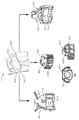
- the figure which shows an example of the doll toy corresponding to an embodiment The perspective view of the head of the doll toy corresponding to the embodiment, and the figure which shows the appearance of each part of a head.
- the perspective view of the body part of the doll toy corresponding to the embodiment and the figure which shows the appearance of each part of the body part.
- the perspective view of the arm part of the doll toy corresponding to the embodiment and the figure which shows the appearance of each part of the arm part.
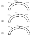
- the figure for demonstrating the state which the surface is continuous corresponding to an embodiment.
- FIG. 1 shows an example of the appearance of the doll toy corresponding to the present embodiment.
- FIG. 1 is a schematic diagram showing a doll toy 100 according to an embodiment.
- the doll toy 100 has model parts of a head portion 110, a body portion 111, an arm portion 112, a waist portion 113, and a leg portion 114, and these are connected to each other.
- At least a portion of the individual sites 110-114 is rotatably (or rocked) supported with respect to adjacent sites.
- the head 110 is rotatably supported with respect to the body portion 111
- the arm portion 112 is rotatably supported with respect to the body portion 111.
- joint structures are provided in each portion of the doll toy 100, and the user (for example, the owner of the doll toy 1) can put such a doll toy 100 in a desired posture.
- one or more decorative parts can be attached to the doll toy 100.
- the decorative parts can also be configured in the same manner as the model parts of the doll toys described in the present embodiment.
- Decorative parts include, for example, weapons such as swords and guns, armor such as shields, and the like. It was
- front front
- rear rear
- left left side
- right right
- top upper
- lower lower
- each model part constituting the doll toy 100 is composed of an internal part made of a thermoplastic resin such as ABS and an external part made of a metal material that covers the outside of the internal part. ..
- the external parts are basically not directly connected to each other, and by connecting the external parts to the internal parts, the relative positions of the plurality of external parts are determined via the same internal parts.
- the external parts When the external parts are bonded to each other, they may be bonded in advance by a sintering process. It was
- ABS is exemplified as a molding material for internal parts in the embodiments described below, but the present invention is not limited to this, and the use of other materials (polyethylene, polystyrene, thermosetting resin, etc.) is not excluded.
- the metal material constituting the external parts can be, for example, an alloy in which titanium, aluminum, and the rare earth yttrium are mixed, but the combination is not limited to this, and at least a part of the combination is different or all of them are different. It may be another different type of alloy, or it may be a single metal such as aluminum. It was
- the molding method of the internal parts is the same as the molding method of a normal plastic model, but the molding method of the external parts can be performed as follows as an example.
- the pellets are heated and melted, pressure-injected into a mold, solidified and molded, and then the binder is removed by sintering to complete the external parts.
- the parts to be combined in advance and then sintering the parts the parts can be combined as an integral external part.
- the sintering results may vary.
- the internal parts absorb the variations of the external parts by connecting the metal external parts and the resin internal parts instead of connecting the external parts of the finished product. It can be resolved. Since the resin parts have a shrinkage rate of less than 1%, they can be almost ignored. It was
- the external part since the shape of the external part may be deformed when the external part is sintered, the external part is configured to suppress the deformation. This is because the external parts do not harden as they are during sintering, but the material becomes soft once, so depending on the shape of the parts, some parts may hang down due to the influence of gravity and the shape may collapse.
- external parts are installed on a flat surface (installation surface) for sintering, but at that time, it is necessary to install the external parts in a well-balanced manner without floating from the installation surface, and if it cannot be placed properly, , The shape of the parts collapses during sintering. Further, if the weight of the part is too heavy, if a large amount of stress is applied to a part of the part, the part may be bent at the time of sintering. It was
- the external parts corresponding to the present embodiment are configured to have a flat surface so that the external parts can be placed in a well-balanced manner without floating from the installation surface during sintering.
- the joint surface between external parts may be constructed flat and installed using this joint surface, or at least a part of the appearance of the external parts may be configured flat and installed using this flat surface. be able to.
- a support protrusion can be provided inside so as not to cause distortion at the time of sintering due to a local weight (stress) being applied to a part of the portion.
- the protrusion can also be used for connection with internal parts.
- the external parts may be supported by the inner protrusions and the flat surface of the outer peripheral portion or the edge portion. At that time, the same plane is formed by the end portion of the protrusion and the flat surface. It was
- FIG. 2 includes a perspective view showing the appearance of the head 110 and a view showing the appearance of the internal parts and the external parts constituting the head 110. It was
- the head 110 is composed of external parts 201, 202, 203 made of a metal material and an internal part 205 made of a resin material.
- the external part 201 is a part arranged on the front side of the head 110, and the external part 202 is attached in advance.
- the external part 203 is a part arranged on the back side of the head 110, which is a surface opposite to the external part 201.
- the internal part 205 is a part for attaching the external part 201 to the front side and the external part 203 to the back side on the opposite side and connecting to the body portion 111.
- the front side, the back side, and the bottom surface are Includes a diagram showing the appearance. Further, in the perspective view of the appearance of the head shown on the upper side of FIG.
- the internal parts 205 are not shown, but are sandwiched between the external parts 201 and 203 and housed inside them.
- the external parts 201 and 202 are pre-bonded by sintering at the time of their formation.
- a plurality of parts may be bonded in advance by sintering to form one part. It was
- the dotted line 204 of the head 110 indicates the boundary between the external parts 201 and 203.
- the outer parts 201 and 203 are joined to the inner part 205 so that the surfaces are continuous before and after the boundary 204.
- the fact that the surface is continuous means that there is a clear step (FIG. 7 (B)) or gap (FIG. 7 (C)) recognized from the outside at the boundary 703 of the external parts 701 and 702 to be connected as shown in FIG. )) Does not occur, and the surface of one external part and the surface of the other external part are smoothly connected (FIG. 7 (A)).
- the external parts do not necessarily have to be continuous before and after the connection boundary. It was
- the outer part 201 on the front side of the head 110 has coupling holes 211, 212 for coupling to the protrusions 221 and 222 on the front surface of the inner part 205.
- the outer part 203 on the back side of the head 110 has protrusions 231 and 232 for connecting to the connection holes 223 and 224 on the back side of the inner part.
- the surface 213 of the external part 201 and the surface 233 of the external part 203 are flat surfaces, and function as surfaces that support the external parts 201 and 203 when the external parts 201 and 203 are installed at the time of sintering. Further, the outer parts 201 and 203 serve as a joining surface when the outer parts 201 and 203 are joined to the inner parts 205, and the boundary 204 is formed at the end thereof. It was
- the internal part 205 has a connection hole 225 at the bottom thereof, and is connected to a ball-shaped protrusion provided on the body portion 111 via the connection hole 205. This makes it possible to orient the head 110 with respect to the body portion 111 in any direction. It was
- FIG. 3 includes a perspective view showing the appearance of the body portion 111, and a view showing the appearance of the internal parts and the external parts constituting the body portion 111. It was
- the body portion 111 is composed of external parts 301, 302, 303 made of a metal material and an internal part 304 made of a resin material.
- the external part 301 is a part arranged on the front side of the body portion 111
- the external part 302 is a part arranged on the back side of the body portion 111 which is a surface opposite to the external part 301.
- the external part 303 is a part located below the external parts 301 and 302 and for connecting to the waist portion 113.
- the internal part 304 is a part for attaching an external part 301 on the front side, an external part 302 on the back side on the opposite side, and an external part 303 on the bottom, and ensuring a connection with the head 110 at the top.
- the joint portion 350 of the internal part 304 with the head portion 110 and the joint portions 351 and 352 with the arm portion 112 are located on the outside of the external part. It is exposed.
- the external parts 301 and 302 are coupled to the internal parts 304 so that the surfaces of the external parts 301 and 302 are continuously formed before and after the boundary between the external parts 301 and 302. It was
- the outer part 301 on the front side of the fuselage portion 111 has protrusions 311 to 314 for connecting to the coupling holes 341 to 344 on the front surface of the inner part 304.
- the outer part 302 on the back side of the fuselage portion 111 has protrusions 321 to 324 for connecting to the joint holes 346 to 349 on the back side of the inner part.
- the external part 303 has a storage hole 331 for accommodating an end portion including the bottom surface of the internal part 304. About the lower half of the inner part 304 is accommodated and fixed in the accommodating hole of the outer part 303.
- the accommodating hole 331 penetrates the bottom surface of the external part 303, and the bottom surface of the internal part 304 is exposed from the bottom surface of the external part 303. Further, the bottom surface of the external part 303 functions as an installation surface of the external part 303 at the time of sintering. It was
- the internal part 304 has a joint portion 350 for rotatably connecting to the head 110, and the joint portion 350 has a ball-shaped shape. Further, it has protrusions 351 and 352 on the left and right, and is rotatably connected to the arm portion 112 by these protrusions 351 and 352. Although not shown in FIG. 3, a connecting hole for connecting to the waist portion 113 is provided on the bottom surface of the internal part 304. The coupling hole is coupled to the protrusion 517 of the internal part 501 of the waist portion 113, which will be described later. It was
- FIG. 4 includes a perspective view showing the appearance of the arm portion 112 and a view showing the appearance of the internal parts and the external parts constituting the arm portion 112. It was
- the arm portion 112 is composed of external parts 401, 403, 407, 408 made of a metal material and internal parts 402, 404, 405, 406 made of a resin material.
- the internal parts 404, 405, and 406 form the elbow joint of the arm portion 112, and the joint portion of the internal part 404 is combined with the internal parts 405 and 406. It is rotatably connected by sandwiching it with. It was
- the external part 401 has a protrusion (not shown) inside, and the protrusion is inserted into the coupling hole 421 of the internal part 402 to connect the external part 401 and the internal part 402.
- the internal part 402 further has a coupling hole (not shown) for rotatably coupling with the coupling portions 351 and 352 of the body portion 111 on the left side surface, and rotatably couples with the protrusion 441 of the internal part 404. Further has a coupling hole (not shown) on the bottom surface. It was
- the external part 403 is a part that constitutes the appearance of the upper arm portion in the arm portion 112, a hole penetrates the inside thereof, and the opening 431 is an opening on the upper side of the through hole.
- the end 432 having the opening 431 forms a flat surface and can function as a surface on which the external part 403 is placed during sintering.
- the opening 442 of the internal part 404 is exposed from the opening at the lower end of the external part 403, and the internal parts 405 and 406 are connected there. It was
- the inner part 404 is housed in the through hole of the outer part 403 to cover its side surface, while the top and bottom are exposed from the outer part 403.
- the internal part 404 further has an opening 442 on the lower side, and the opening formed in the protrusion 451 of the internal part 405 and the protrusion 461 of the internal part 406 are connected to each other via the opening 442.
- the internal part 404 is sandwiched between the internal parts 405 and 406. As a result, the internal parts 405 and 406 are rotatably coupled to the internal parts 404. It was
- the inner parts 405 and 406 are housed in the outer parts 407 to cover their sides, but the top and bottom are exposed.
- the bottom of the internal part 405 is provided with a connecting hole to which the protrusion 481 of the fist part 408 is connected.
- the external part 407 is a part that constitutes the appearance of the forearm portion in the arm portion 112, a hole penetrates the inside thereof, and the opening 471 is an opening on the upper side of the through hole.
- the side surface 472 of the external part 407 forms a flat surface on at least one surface and can function as a surface on which the external part 407 is placed during sintering.
- the bottom of the internal part 405 is exposed from the opening at the lower end of the external part 407, and the fist part 408 is connected there.
- the fist part 408 is a part that imitates the shape of a doll's hand, and is provided with an opening 481 for connecting an external part. It was
- FIG. 5 includes a perspective view showing the appearance of the waist portion 113 and a view showing the appearance of the internal parts and the external parts constituting the waist portion 113. It was
- the waist portion 113 is composed of an external part 502, 503, 504, 505, 506, 507 made of a metal material and an internal part 501 made of a resin material.
- the external parts 502 to 507 have contrasting arrangements and structures in the left-right and front-rear directions, and the internal parts 501 are also configured in contrast in the front-back and left-right directions. There is. It was
- the internal part 501 has left and right protrusions 511 and 512, and the protrusions 511 are locked to the coupling hole 541 of the external part 504 to connect the external part 504 to the internal part 501. be able to.
- the external part 505 can also be coupled to the internal part 501 via the protrusion 512 in the same manner. It was
- the internal parts 501 have front and rear protrusions 513 and 514 for front and rear coupling with the external parts 502 and 506.
- the protrusions 513 and 514 are coupled to the coupling holes provided on the back side of the external part 502.
- FIG. 5 only the protrusions 513 and 514 on the front surface are shown, but two protrusions are similarly arranged on the back surface.
- the protrusion on the back surface is coupled to the coupling holes 561 and 562 of the external part 506.
- the shaft portion 571 of the external part 507 is locked by the recess 563 of the external part 506, so that the external part 507 is rotatably coupled to the external part 506 with the shaft 571 as the rotation axis.
- the external part 503 is rotatably coupled to the external part 502 with the shaft 531 as the rotation axis.
- the internal part 501 further comprises protrusions 515 and 516 for coupling to the legs 114.
- the leg 114 is coupled to the lumbar 113 via the protrusions 515 and 516.
- a protrusion 517 for connecting to a coupling hole on the bottom surface of the external part 303 of the body portion 111 is provided on the top portion.
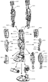
- FIG. 6 includes a perspective view showing the appearance of the leg portion 114 and a view showing the appearance of the internal parts and the external parts constituting the leg portion 114. It was
- the leg portion 114 is composed of external parts 603, 604, 605, 606, 607, 608, 609, 610, 612 made of a metal material and internal parts 601, 602, 611 made of a resin material. It was
- the joints of the legs 114 that is, the knee joints and the ankle joints, are fixed. This is because parts made of metal material are used, so the weight is heavier than that of ordinary plastic material.
- the internal parts of the legs 114 are formed by connecting the internal parts 601 and 602. In FIG. 6, two internal parts are combined, but three or more may be used. By combining multiple parts, the thickness of the internal parts can be increased and the strength can be increased.
- An opening 621 is formed in the internal part 602, and is configured to be connectable to a protrusion 515 or 516 of the internal part 501 of the waist portion 113. Further, by connecting the lower end portions 613 and 622 of the internal parts 601 and 602 and inserting them into the opening of the top of the internal parts 611 constituting the ankle portion, the internal parts 611 are connected to the internal parts 611. The internal part 611 is coupled to the external parts 610 and 612. It was
- External parts 603 to 609 are connected to the internal parts 601 and 602, respectively. These external parts have a coupling hole that is coupled to a protrusion formed on the surface of the internal parts 601 and 602, or a protrusion that is coupled to a coupling hole formed on the surface of the internal parts 601 and 602. There is. It was
- the external parts 603 and 604 are connected to the internal parts 601 and 602 so that the surfaces of the external parts 603 and 604 are continuously formed before and after the boundary between the external parts 603 and 604. .. The same applies to other external parts. It was
- the internal parts are arranged so as to sandwich the internal parts from the left and right like the external parts 608 and 609. Parts are also included. Further, in the external parts 603 and 604, the structure can be subdivided so as to cover the internal parts with the external parts 605, 606, 607, 608 and 609, while the two can cover the periphery of the internal parts. It is possible.
- the external parts 605 arranged on the front side the external parts 608 and 609 are arranged on the right side surface and the left side surface connected to the front side, and the external parts 606 are further connected to the back surface connected to each side surface.
- an external part 607 is arranged below the external par 605, and each part is connected to the internal parts 601 and 602 so that the surface of a part of the external part 607 and each part of the external parts 608 and 609 are continuous. do. It was
- the external parts 605 are provided with protrusions 651 and 652, respectively, on which a coupling hole is formed.
- the coupling holes of the protrusions 651 and 652 combine with the corresponding protrusions of the inner part 601 while the protrusions 651 and 652 are used to support the outer part 605 during sintering.
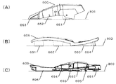
- FIG. 8A is a side view of the external part 605, but the ends of the protrusions 651 and 652 and the end 653 of the external part 605 are configured to form the same plane 801. ..
- the external parts 605 can be installed in a well-balanced manner without floating from the installation surface during sintering. It was
- the external parts 606 are provided with protrusions 661, 662 and 663 in which coupling holes are formed, respectively, and are provided with protrusions 664.
- the coupling holes of the protrusions 661 to 663 combine with the corresponding protrusions of the inner part 601 while the protrusions 661 to 664 are used to support the outer part 606 during sintering.
- FIG. 8B is a side view of the external part 606, but the ends of the protrusions 661 to 664 are configured to form the same plane 802. As a result, the external parts 606 can be installed in a well-balanced manner without floating from the installation surface during sintering. It was
- the external parts 609 are provided with protrusions 691 to 696.
- the protrusions 691 to 694 combine with the corresponding coupling holes of the inner part 602, while the protrusions 691 to 696 are used to support the outer part 609 during sintering.
- FIG. 8C is a side view of the external part 609, and the ends of the protrusions 691 to 696 are configured to form the same plane 803.
- the external parts 609 do not float from the installation surface during sintering, and can be installed in a well-balanced manner. It was
- FIG. 9 shows an example of a shield 900 configured to be attached to the doll toy 100.
- the shield 900 also constitutes a toy part of the doll toy 100.
- the shield 900 is configured by connecting the outer part 901 and the inner part 902, and the edges of the outer part 901 form the same plane when viewed from the side surface direction.
- the outer part 901 has protrusions 910 to 917 for connecting to the inner part 902, and the inner part 902 has connection holes 920 to 927 for connecting to the protrusions 910 to 917 of the outer part 901. ing. Since the external part 901 is larger than the internal part 902, when the external part 901 and the internal part 902 are combined, the connection surface of the internal part 902 is covered by the external part 901. Further, the tips of the protrusions 910 to 917 of the outer part are exposed from the joint holes 920 to 927 of the inner part, and the regular arrangement and shape of the protrusions 910 to 917 bring about a decorative effect. It was
- the ends of the protrusions 910 to 917 of the external part 901 form a coplanar surface with the edge 918 of the external part 901 and function to support the external part 901 when the external part 901 is sintered.
- the external parts 609 do not float from the installation surface during sintering, and can be installed in a well-balanced manner. If the external part 901 is to be supported only by the edge portion 918 at the time of sintering, deformation is unavoidable due to the weight of the central portion of the external part 901, but since the protrusions 910 to 917 function as the support portion, it is external. Sintering can be performed while maintaining the shape of the part 901 as a whole. It was
- the opening 903 is a connection hole for attaching a mounting member for mounting the shield 900 to the doll toy 100, and for example, a mounting member for mounting on the arm of the doll toy 100 can be attached. It was
- the model part of the doll toy can be composed of a combination of an external part made of a metal material and an internal part made of a resin material.
- the user's stress can be reduced because the metal parts can be easily assembled as compared with the case where the metal parts are joined and assembled.
- the variation generated in the external parts during sintering can be absorbed by the internal parts made of resin, it is possible to solve the problems during assembly.
- by forming the skeleton part with resin parts it is possible to reduce the thickness of the metal parts that make up the appearance, and to reduce the weight of the doll toy as a whole. Is possible. It was
Landscapes
- Toys (AREA)
Abstract
【課題】金属材料からなるパーツを用いた場合にも簡易に組み立て可能な玩具部品を提供する。【解決手段】玩具部品であって、樹脂材料からなる第1の部材と、前記第1の部材の第1の面と結合する、金属材料からなる第2の部材と、前記第1の部材の第2の面と結合する、前記金属材料からなる第3の部材とを備え、前記第2の部材と前記第3の部材とが前記第1の部材に結合されると、前記第1の部材は少なくとも部分的に前記第2の部材と前記第3の部材とにより覆われることを特徴とする。
Description
本発明は、玩具部品、関節機構、人形玩具及び装飾部品に関する。
特許文献1には、プラスチック製のパーツが表裏2個で1組となって組み立てられるプラスチックモデルが記載されている。当該プラスチック製のパーツに凹凸が形成されており、これを組み合わせることでパーツが結合される。
金属材料からなるパーツの場合、材料の性質に起因して、プラスチック製のパーツのように凹凸を用いて簡単に結合することができない。
本発明は、金属材料からなるパーツを用いた場合にも簡易に組み立て可能な玩具部品等を提供することを目的とする。
本発明は、玩具部品であって、 樹脂材料からなる第1の部材と、 前記第1の部材の第1の面と結合する、金属材料からなる第2の部材と、 前記第1の部材の第2の面と結合する、前記金属材料からなる第3の部材とを備え、 前記第2の部材と前記第3の部材とが前記第1の部材に結合されると、前記第1の部材は少なくとも部分的に前記第2の部材と前記第3の部材とにより覆われることを特徴とする。
本発明によれば、金属材料からなるパーツを用いた場合にも簡易に組み立て可能な玩具部品等を提供することができる。
以下、添付図面を参照して実施形態を詳しく説明する。尚、以下の実施形態は特許請求の範囲に係る発明を限定するものではなく、また実施形態で説明されている特徴の組み合わせの全てが発明に必須のものとは限らない。実施形態で説明されている複数の特徴うち二つ以上の特徴が任意に組み合わされてもよい。また、同一若しくは同様の構成には同一の参照番号を付し、重複した説明は省略する。また、各図において、紙面に対する上下左右表裏方向を、本実施形態における部品(またはパーツ)の上下左右表裏方向として、本文中の説明の際に用いることとする。
まず、本実施形態に対応する人形玩具の外観の一例を図1に示す。図1は、実施形態に係る人形玩具100を示す模式図である。人形玩具100は、頭部110、胴体部111、腕部112、腰部113、及び、脚部114の各模型部品を有し、これらが結合されて構成されている。個々の部位110~114の少なくとも一部は、隣接する部位に対して回動(或いは揺動)可能に支持される。例えば、頭部110は胴体部111に対して回動可能に支持され、腕部112は胴体部111に対して回動可能に支持される。このようにして人形玩具100の各部位には関節構造が設けられており、ユーザ(例えば、人形玩具1の所有者)は、このような人形玩具100を所望の姿勢にすることができる。図1では、省略しているが、人形玩具100には1つ以上の装飾部品を取り付けることができる。装飾部品も本実施形態で説明する人形玩具の模型部品と同様に構成することができる。装飾部品には、例えば、剣や銃のような武器や、盾のような防具等がある。
尚、本明細書においては、各部位の位置関係を説明するのに際して、前(前方)、後(後方)、左(左側方)、右(右側方)、上(上方)、下(下方)等と記載する場合があるが、これらの表現は人形玩具1を基準とした相対的なものである。例えば、前は人形玩具100正面側に対応し、後は人形玩具100背面側に対応する。
本実施形態において、人形玩具100を構成する各模型部品は、ABS等の熱可塑性樹脂により構成された内部パーツと、当該内部パーツの外側を覆う金属材料で構成された外部パーツとで構成される。外部パーツ同士は基本的には直接結合されず、内部パーツに対して外部パーツを結合することにより、同一の内部パーツを介して複数の外部パーツの相対的位置が決定される。外部パーツ同士を結合する場合には、焼結処理により予め結合されていてもよい。
以下に説明する実施形態おいて内部パーツの成型材料としてABSを例示するがこれに限定されず、他の材質(ポリエチレン、ポリスチレン、熱硬化性樹脂等)の利用を排除するものではない。また、外部パーツを構成する金属材料は、例えば、チタニウム、アルミニウム、希土類イットリアを混合した合金とすることができるが、これに限られるものではなく、組み合わせの少なくとも一部が異なる、或いは、全てが異なる他の種類の合金であってもよいし、或いは、アルミニウムのような単一金属であってもよい。
内部パーツの成型方法は通常のプラスチックモデルの成型方法と同様であるが、外部パーツの成型方法は、一例として以下の通りに行うことができる。まず、チタニウム、アルミニウム、希土類イットリウムの原料粉末をバインダと混ぜ合わせてペレットを生成する。当該ペレットを加熱溶融して金型内に加圧注入し、固化させて成型を行ったのち、焼結によりバインダを除去することで、外部パーツが完成する。なお、結合対象のパーツ同士を予め組み合わせてから焼結を行うことで、一体の外部パーツとして結合させることができる。また、焼結時に外部パーツは12パーセント程度収縮するため、焼結結果にばらつきが出るおそれがある。しかし、このようなばらつきも、完成品の外部パーツ同士を結合するのではなく、金属製の外部パーツと樹脂製の内部パーツとを結合させることで、内部パーツが外部パーツのばらつきを吸収するので解消できる。なお、樹脂製パーツは収縮率が1%未満であるため、ほぼ無視することができる。
また、外部パーツの焼結時には、パーツ形状が変形するおそれがあるため、外部パーツは当該変形を抑制するように構成される。というのも、外部パーツは焼結時にそのまま固くなっていくわけではなく、一旦材料が柔らかくなるため、パーツ形状によっては重力の影響で一部が垂れ下がるなどして形状が崩れてしまうことがある。一般には、外部パーツを平面(設置面)に設置して焼結を行うものであるが、その際に外部パーツが設置面から浮くことなくバランスよく設置する必要があり、上手く置けない場合には、焼結時にパーツの形状が崩れてしまう。また、パーツの重量が重すぎる場合には一部に応力が大きくかかってしまうと焼結時に曲がってしまうおそれがある。
そこで、本実施形態に対応する外部パーツは、焼結時に外部パーツが設置面から浮くこと無く、バランスよく置けるよう、平坦面を有するように構成されている。例えば、外部パーツ同士の接合面を平坦に構成し、この接合面を利用して設置したり、外部パーツの外観の少なくとも一部を平坦に構成し、この平坦面を利用して設置したりすることができる。また、一部分に局所的に重量(応力)がかかることによる焼結時のゆがみが生じないように、内部に支持用の突起部を設けることができる。当該突起部は、内部パーツとの接続にも利用できる。また、焼結時には、内側の突起部と、外周部分或いは縁部分の平坦面とにより外部パーツを支持するようにしてもよい。その際、突起部の端部と平坦面とにより同一平面が形成される。
次に図2を参照して、頭部110の模型部品の構成例を説明する。図2は、頭部110の外観を示す斜視図と、頭部110を構成する内部パーツ及び外部パーツの外観を示す図とを含む。
頭部110は、金属材料からなる外部パーツ201、202、203と、樹脂材料からなる内部パーツ205とで構成されている。外部パーツ201は、頭部110の正面側に配置されるパーツであり、外部パーツ202が予め取り付けられている。外部パーツ203は、外部パーツ201とは反対側の面である頭部110の背面側に配置されるパーツである。内部パーツ205は、正面側に外部パーツ201、反対側の背面側に外部パーツ203を取り付けると共に、胴体部111と接続するためのパーツであり、図2においては、正面側、背面側、底面の外観を示す図を含めている。また、図2の上側に示す頭部外観の斜視図においては、内部パーツ205は示されていないが、外部パーツ201と203とに挟まれて、それらの内部に収容されている。外部パーツ201と202とは、その生成時に焼結により予め結合されている。これ以降で説明する外部パーツについても、複数のパーツを焼結により予め結合して1つのパーツとして構成してもよい。
頭部110の点線204は、外部パーツ201と203との境界を示している。外部パーツ201と203とは、境界204の前後で表面が連続するように内部パーツ205に対して結合される。ここで、表面が連続するとは、図7に示すような接続対象の外部パーツ701、702の境界703において、外側から認識される明らかな段差(図7(B))や隙間(図7(C))が生じておらず、一方の外部パーツの表面と他方の外部パーツの表面とが滑らかに接続されている状態(図7(A))をいう。以下同様である。但し、本実施形態において、外部パーツを結合する際に、接続境界の前後において外部パーツ同士が必ずしも連続していなくてはならない訳ではない。
頭部110の正面側の外部パーツ201は、内部パーツ205の前面の突起部221、222と結合するための結合孔211、212を有する。頭部110の背面側の外部パーツ203は、内部パーツの背面の結合孔223、224と結合するための突起部231、232を有する。外部パーツ201の面213と、外部パーツ203の面233とは平坦面であって、焼結時に外部パーツ201、203を設置する際に、外部パーツ201、203をそれぞれ支持する面として機能する。また、外部パーツ201、203が内部パーツ205と結合する際の結合面となり、その端部において境界204を構成する。
内部パーツ205は、底部に接続孔225を有しており、当該接続孔205を介して胴体部111に設けられたボール状の突起部と結合する。これにより、胴体部111に対して頭部110を任意の方向に向けることが可能となる。
次に図3を参照して、胴体部111の模型部品の構成例を説明する。図3は、胴体部111の外観を示す斜視図と、胴体部111を構成する内部パーツ及び外部パーツの外観を示す図とを含む。
胴体部111は、金属材料からなる外部パーツ301、302、303と、樹脂材料からなる内部パーツ304とで構成されている。外部パーツ301は胴体部111の正面側に配置されるパーツであり、外部パーツ302は外部パーツ301とは反対側の面である胴体部111の背面側に配置されるパーツである。外部パーツ303は、外部パーツ301、302の下方に位置し、かつ、腰部113と接続するためのパーツである。内部パーツ304は、正面側に外部パーツ301、反対側の背面側に外部パーツ302、底部に外部パーツ303を取り付けると共に、頂部において頭部110との接続を確保するためのパーツである。図3においては、内部パーツ304については、正面側、背面側の外観を示
す図を含めている。また、図3の上側に示す胴体部外観の斜視図においては、内部パーツ304の、頭部110との結合部350、及び、腕部112との結合部351、352が、外部パーツの外側に露出している。
す図を含めている。また、図3の上側に示す胴体部外観の斜視図においては、内部パーツ304の、頭部110との結合部350、及び、腕部112との結合部351、352が、外部パーツの外側に露出している。
胴体部111においても、外部パーツ301と302との境界の前後において、外部パーツ301及び302の表面が連続して形成されるように、外部パーツ301及び302は内部パーツ304に結合される。
胴体部111の正面側の外部パーツ301は、内部パーツ304の前面の結合孔341から344と結合するための突起部311から314を有する。胴体部111の背面側の外部パーツ302は、内部パーツの背面の結合孔346から349と結合するための突起部321から324を有する。また、外部パーツ303は、内部パーツ304の底面を含む端部を収容するための収容孔331を有する。内部パーツ304は下側の約半分が外部パーツ303の収容孔に収容されて固定される。図3には不図示であるが、収容孔331は外部パーツ303の底面を貫通しており、内部パーツ304の底面が外部パーツ303の底面から露出している。また、外部パーツ303の底面は、焼結時に外部パーツ303の設置面として機能する。
内部パーツ304は、頭部110と回動可能に結合するための結合部350を有しており、当該結合部350はボール状の形状を有する。また、左右に突起部351、352を有しており、これらの突起部351、352により腕部112と回動可能に結合する。図3には不図示であるが、内部パーツ304の底面には、腰部113と結合するための結合孔が設けられている。当該結合孔は、後述する腰部113の内部パーツ501の突起部517と結合する。
次に図4を参照して、腕部112の模型部品の構成例を説明する。図4は、腕部112の外観を示す斜視図と、腕部112を構成する内部パーツ及び外部パーツの外観を示す図とを含む。
腕部112は、金属材料からなる外部パーツ401、403、407、408と、樹脂材料からなる内部パーツ402、404、405、406とで構成されている。図4の中央に示す腕部外観の正面図においては、内部パーツ404、405、406は、腕部112の肘関節を構成しており、内部パーツ404の結合部を、内部パーツ405と406とで挟み込むことで回動可能に結合される。
外部パーツ401は、内部に不図示の突起部を有しており、当該突起部は内部パーツ402の結合孔421に挿入されて、外部パーツ401と内部パーツ402とが結合する。内部パーツ402は、胴体部111の結合部351、352と回動可能に結合するための不図示の結合孔を左側面に更に有すると共に、内部パーツ404の突起部441と回動可能に結合するための不図示の結合孔を底面に更に有する。
外部パーツ403は腕部112において上腕部の外観を構成するパーツであり、その内部は孔が貫通しており、開口431は当該貫通孔の上側の開口である。開口431を有する端部432は平坦面を形成し、焼結時には外部パーツ403を設置する面として機能しうる。外部パーツ403の下端の開口から内部パーツ404の開口442が露出し、そこに内部パーツ405、406が結合される。
内部パーツ404は外部パーツ403の当該貫通孔に収容されることにより、その側面が覆われる一方、頂部と底部とが外部パーツ403から露出している。内部パーツ404は下側に開口部442を更に有しており、内部パーツ405の突起部451に形成された開口部と内部パーツ406の突起部461とが、開口部442を介して結合しつつ、内部パーツ405と406とで内部パーツ404を挟みこむ。これにより、内部パーツ405と406とが、内部パーツ404に対して回動可能に結合される。
内部パーツ405及び406は、外部パーツ407に収容されることにより、その側面が覆われるが、頂部と底部が露出している。内部パーツ405の底部には拳パーツ408の突起部481が結合される結合孔が設けられている。外部パーツ407は腕部112において前腕部の外観を構成するパーツであり、その内部は孔が貫通しており、開口471は当該貫通孔の上側の開口である。外部パーツ407の側面472は、少なくとも1つの面において平坦面を形成し、焼結時には外部パーツ407を設置する面として機能しうる。外部パーツ407の下端の開口から内部パーツ405の底部が露出し、そこに拳パーツ408が結合される。拳パーツ408は、人形の手の形を模したパーツであって、外部パーツを接続するために開口481が設けられている。
次に図5を参照して、腰部113の模型部品の構成例を説明する。図5は、腰部113の外観を示す斜視図と、腰部113を構成する内部パーツ及び外部パーツの外観を示す図とを含む。
腰部113は、金属材料からなる外部パーツ502、503、504、505、506、507と、樹脂材料からなる内部パーツ501とで構成されている。図5の中央に示す腰部外観の斜視図においては、外部パーツ502から507は、左右及び前後において対照的な配置及び構造を有しており、内部パーツ501も前後左右において対照的に構成されている。
内部パーツ501は、左右の突起部511、512を有しており、当該突起部511が外部パーツ504の結合孔541に係止されることにより、内部パーツ501に対して外部パーツ504を結合することができる。外部パーツ505についても同様にして突起部512を介して内部パーツ501と結合することができる。
内部パーツ501は外部パーツ502、506と前後で結合するための突起部513、514を前後に有している。突起部513、514は外部パーツ502が裏側に備える結合孔と結合する。図5では、前面の突起部513、514のみを示しているが、背面にも同様に2つの突起部が配置されている。背面の突起部は外部パーツ506の結合孔561、562と結合する。その際、外部パーツ507の軸部571が外部パーツ506の凹部563により係止されることにより、外部パーツ507が軸571を回転軸として、外部パーツ506に対して回動可能に結合される。外部パーツ503についても、同様にして軸531を回動軸として、外部パーツ502に回動可能に結合される。
内部パーツ501は、脚部114と結合するための突起部515、516を更に有する。当該突起部515、516を介して、脚部114が腰部113と結合される。また、頂部に胴体部111の外部パーツ303の底面の結合孔と結合するための突起部517が設けられている。当該突起部517が、内部パーツ304の底面の結合孔と結合することにより、胴体部111が腰部113と回動可能に結合される。
次に、図6を参照して脚部114の模型部品の構成例を説明する。図6は、脚部114の外観を示す斜視図と脚部114を構成する内部パーツ及び外部パーツの外観を示す図とを含む。
脚部114は、金属材料からなる外部パーツ603、604、605、606、607、608、609、610、612と、樹脂材料からなる内部パーツ601、602、611とで構成されている。
本実施形態において、脚部114の関節、即ち、膝関節及び足首関節は固定されている。これは、金属材料のパーツを使用しているので、重量が通常のプラスチック材料の場合よりも重たいためである。脚部114の膝及び足首の関節を固定することで、人形玩具100のポーズを安定的に維持することが可能となる。
脚部114の内部パーツは、内部パーツ601と602とが結合して構成されている。図6では、2つの内部パーツを組み合わせているが、3つ以上としてもよい。複数のパーツを組み合わせることにより、内部パーツの厚みを出して強度を高めることができる。内部パーツ602には、開口部621が形成されており、腰部113の内部パーツ501の突起部515又は516と結合可能に構成されている。また、内部パーツ601と602の下側端部613、622を結合して、足首部分を構成する内部パーツ611の頂部の開口に挿入することで、内部パーツ611と結合される。当該内部パーツ611は、外部パーツ610、612と結合する。
内部パーツ601、602には、外部パーツ603から609がそれぞれ接続される。これらの外部パーツは内部パーツ601、602の表面に形成された突起部と結合される結合孔、又は、内部パーツ601、602の表面に形成された結合孔と結合される突起部を有している。
脚部114においても、外部パーツ603と604との境界の前後において、外部パーツ603及び604の表面が連続して形成されるように、外部パーツ603及び604は内部パーツ601、602に結合される。その他の外部パーツについても同様である。
また、脚部114においては、外部パーツ603、604のように、前後から内部パーツを挟み込むように配置されるパーツの他、外部パーツ608、609のように左右から内部パーツを挟み込むように配置されるパーツも含まれる。また、外部パーツ603、604では、2つで内部パーツの周囲を覆うことができるのに対し、外部パーツ605、606、607、608、609で内部パーツを覆うように構造を細分化することも可能である。このとき、正面側に配置される外部パーツ605に対し、正面と接続する右側面、左側面に外部パーツ608、609が配置され、更に各側面と接続する背面に外部パーツ606が接続される。更に、外部パー605の下方には外部パーツ607が配置され、外部パーツ607の一部分と、外部パーツ608、609の各一部分との表面が連続するように、各パーツが内部パーツ601、602と結合する。
外部パーツ605には、それぞれ結合孔が形成された突起部651及び652が設けられる。突起部651及び652の結合孔は内部パーツ601の対応する突起部と結合する一方で、突起部651及び652は焼結時に外部パーツ605を支持するのに用いられる。図8(A)は、外部パーツ605を側面から見た図であるが、突起部651及び652の端部と、外部パーツ605の端部653は同一平面801を形成するように構成されている。これにより、焼結時に外部パーツ605が設置面から浮くこと無く、バランスよく設置することができる。
外部パーツ606には、それぞれ結合孔が形成された突起部661、662及び663が設けられると共に、突起部664が設けられている。突起部661から663の結合孔は内部パーツ601の対応する突起部と結合する一方で、突起部661から664は焼結時に外部パーツ606を支持するのに用いられる。図8(B)は、外部パーツ606を側面から見た図であるが、突起部661から664の端部は同一平面802を形成するように構成されている。これにより、焼結時に外部パーツ606が設置面から浮くこと無く、バランスよく設置することができる。
また、外部パーツ609には突起部691から696が設けられている。突起部691から694は内部パーツ602の対応する結合孔と結合する一方で、突起部691から696は焼結時に外部パーツ609を支持するのに用いられる。図8(C)は、外部パーツ609を側面から見た図であるが、突起部691から696の端部は同一平面803を形成するように構成されている。これにより、焼結時に外部パーツ609が設置面から浮くこと無く、バランスよく設置することができる。
次に、図9を参照して、人形玩具100の装飾部品の一例を説明する。図9は、人形玩具100に装着することが可能に構成された盾900の一例を示す。当該盾900も人形玩具100の玩具部品を構成する。盾900は、外部パーツ901と内部パーツ902とが結合されて構成されており、側面
方向から見ると外部パーツ901の縁部は同一平面を形成している。
方向から見ると外部パーツ901の縁部は同一平面を形成している。
外部パーツ901は、内部パーツ902と結合するための突起部910から917を有しており、内部パーツ902は外部パーツ901の突起部910から917と結合するための結合孔920から927を有している。外部パーツ901は内部パーツ902よりも大きいため、外部パーツ901と内部パーツ902とが結合すると、内部パーツ902の接続面は外部パーツ901により覆われる。また、内部パーツの結合孔920から927から外部パーツの突起部910から917の先端が露出し、その規則的な配置や形状により装飾的効果がもたらされる。
外部パーツ901の突起部910から917の端部は、外部パーツ901の縁部918と共に同一平面を形成し、外部パーツ901の焼結時に外部パーツ901を支持するように機能する。これにより、焼結時に外部パーツ609が設置面から浮くこと無く、バランスよく設置することができる。なお、焼結時に外部パーツ901を縁部918だけで支持しようとした場合には外部パーツ901の中央部分の重さにより変形を免れないが、突起部910から917が支持部として機能するので外部パーツ901の形状を全体として維持した状態で焼結を行うことができるようになる。
開口903は、人形玩具100に盾900を装着するための装着用部材を取り付けるための接続孔であり、例えば、人形玩具100の腕に取り付けるための装着用部材を取り付けることができる。
このように、本実施形態によれば、人形玩具の模型部品を、金属材料からなる外部パーツと、樹脂材料からなる内部パーツとの組み合わせにより構成することができる。これにより、金属パーツ同士を結合させて組み立てる場合に比べて、簡単に組み立てが行えるので、ユーザのストレスを軽減することができる。特に、焼結時に外部パーツに生じたばらつきも樹脂製の内部パーツにより吸収することができるので、組み立て時の不具合を解消することができる。また、全てを金属パーツとするのに比べ、骨格となる部分を樹脂パーツで構成することにより、外観を構成する金属パーツの厚みを薄くすることが可能となり、人形玩具全体として軽量化を図ることが可能となる。
発明は上記の実施形態に制限されるものではなく、発明の要旨の範囲内で、種々の変形・変更が可能である。
Claims (20)
- 玩具部品であって、 樹脂材料からなる第1の部材と、 前記第1の部材の第1の面と結合する、金属材料からなる第2の部材と、 前記第1の部材の第2の面と結合する、前記金属材料からなる第3の部材とを備え、 前記第2の部材と前記第3の部材とが前記第1の部材に結合されると、前記第1の部材は少なくとも部分的に前記第2の部材と前記第3の部材とにより覆われることを特徴とする玩具部品。
- 前記第2の部材と前記第3の部材とは、前記第2の部材と前記第3の部材との表面が連続するように前記第1の部材と結合することを特徴とする請求項1に記載の玩具部品。
- 前記第1の部材は、前記樹脂材料からなる第4の部材と結合する結合部を有し、 前記第2の部材と前記第3の部材とが前記第1の部材と結合された場合に、前記結合部は前記第2の部材及び前記第3の部材により覆われずに露出されることを特徴とする請求項1または2に記載の玩具部品。
- 前記第1の部材は突起部を有し、前記第2の部材及び前記第3の部材の少なくともいずれかが有する結合孔と前記突起部とが結合することにより、前記第1の部材は、前記第2の部材及び前記第3の部材の少なくともいずれかと結合することを特徴とする請求項1から3のいずれか1項に記載の玩具部品。
- 前記第1の部材は結合孔を有し、前記第2の部材及び前記第3の部材の少なくともいずれかが有する突起部と前記結合孔とが結合することにより、前記第1の部材は、前記第2の部材及び前記第3の部材の少なくともいずれかと結合することを特徴とする請求項1から4のいずれか1項に記載の玩具部品。
- 前記第2の部材及び前記第3の部材の少なくともいずれかは複数の突起部を有し、前記複数の突起部には前記結合孔がそれぞれ形成され、前記複数の前記突起部の端部は同一平面を形成する、請求項4に記載の玩具部品。
- 前記第2の部材及び前記第3の部材の少なくともいずれかは複数の前記突起部を有し、前記複数の前記突起部の端部は同一平面を形成する、請求項5に記載の玩具部品。
- 前記複数の突起部の端部と、該複数の突起部を有する前記第2の部材及び前記第3の部材の少なくともいずれかの縁部とが同一平面を形成する、請求項6または7に記載の玩具部品。
- 前記第2の部材と前記第3の部材の少なくともいずれかは平坦面を有し、前記平坦面により設置面に設置された場合に安定的に設置される、請求項1から8のいずれか1項に記載の玩具部品。
- 前記第2の面は、前記第1の面の反対側の面、又は、前記第1の面と接続する面であることを特徴とする請求項1から9のいずれか1項に記載の玩具部品。
- 前記第2の部材と前記第3の部材のうちの少なくともいずれかは、前記金属材料からなる複数の部材が焼結により予め結合されて構成されていることを特徴とする請求項1から10のいずれか1項に記載の玩具部品。
- 前記第1の部材は、前記樹脂材料からなる複数の部材が結合されて構成されていることを特徴とする請求項1から11のいずれか1項に記載の玩具部品。
- 前記金属材料からなる第5の部材を更に備え、 前記第5の部材は、前記第1の部材の底面側の端部を収容することにより前記第1の部材と結合され、 前記第5の部材の底面には、他の玩具部品と結合するための結合部が設けられていることを特徴とする請求項1から12のいずれか1項に記載の玩具部品。
- 玩具部品であって、 樹脂材料からなる第1の部材と、 前記第1の部材の側面を覆うように結合する金属材料からなる第2の部材と、を備え、 前記第1の部材は、頂部及び底部の少なくともいずれかに他の部材と結合するための結合部を有し 前記第1の部材と前記第2の部材とが結合された場合に、前記第1の部材の前記結合部は前記第2の部材により覆われずに露出されることを特徴とする玩具部品。
- 前記他の部材は、前記樹脂材料または前記金属材料からなることを特徴とする請求項14に記載の玩具部品。
- 前記第2の部材は平坦面を有し、前記平坦面により設置面に設置された場合に安定的に設置される、請求項14または15に記載の玩具部品。
- 前記第1の部材は、前記樹脂材料からなる複数の部材が結合されて構成され、 前記第2の部材は、金属材料からなる複数の部材が焼結により予め結合されて構成されたことを特徴とする請求項14から16のいずれか1項に記載の玩具部品。
- 請求項14に記載の第1の玩具部品と、 請求項14に記載の第2の玩具部品と、を備え、 前記第1の玩具部品は、少なくとも底部に第1の結合部を有し、 前記第2の玩具部品は、少なくとも頂部に第2の結合部を有し、 前記第1の結合部と前記第2の結合部とが回動可能に結合されて構成される関節機構。
- 請求項1から17のいずれか1項に記載の玩具部品と、請求項18に記載の関節機構とを有する人形玩具。
- 請求項19に記載の人形玩具の装飾部品であって、 樹脂材料からなる第1の部材と、 前記第1の部材の第1の面と結合する、金属材料からなる第2の部材と、を備え、 前記第1の部材は複数の結合孔を有し、 前記第2の部材は前記複数の結合孔のそれぞれと結合する複数の突起部を有し、 前記第1の部材と前記第2の部材とが結合されると、前記第1の部材の前記第1の面が前記第2の部材により覆われ、前記第1の面と反対側の第2の面において、前記複数の結合孔のそれぞれの開口から前記複数の突起部の端部が露出し、 前記複数の突起部の端部は同一平面を形成する、装飾部品。
Applications Claiming Priority (2)
| Application Number | Priority Date | Filing Date | Title |
|---|---|---|---|
| JP2020-115958 | 2020-07-03 | ||
| JP2020115958A JP7093813B2 (ja) | 2020-07-03 | 2020-07-03 | 玩具部品、関節機構、人形玩具及び装飾部品 |
Publications (1)
| Publication Number | Publication Date |
|---|---|
| WO2022004262A1 true WO2022004262A1 (ja) | 2022-01-06 |
Family
ID=78163095
Family Applications (1)
| Application Number | Title | Priority Date | Filing Date |
|---|---|---|---|
| PCT/JP2021/021181 Ceased WO2022004262A1 (ja) | 2020-07-03 | 2021-06-03 | 玩具部品、関節機構、人形玩具及び装飾部品 |
Country Status (3)
| Country | Link |
|---|---|
| JP (2) | JP7093813B2 (ja) |
| CN (2) | CN113559523B (ja) |
| WO (1) | WO2022004262A1 (ja) |
Cited By (1)
| Publication number | Priority date | Publication date | Assignee | Title |
|---|---|---|---|---|
| WO2023195379A1 (ja) * | 2022-04-08 | 2023-10-12 | 株式会社バンダイ | 人形 |
Families Citing this family (2)
| Publication number | Priority date | Publication date | Assignee | Title |
|---|---|---|---|---|
| JP7045517B1 (ja) * | 2021-12-08 | 2022-03-31 | 株式会社バンダイ | 模型部品、及び人形玩具 |
| JP7741933B1 (ja) | 2024-06-19 | 2025-09-18 | 株式会社バンダイ | 人形体 |
Citations (1)
| Publication number | Priority date | Publication date | Assignee | Title |
|---|---|---|---|---|
| JPS5262190U (ja) * | 1975-10-30 | 1977-05-07 |
Family Cites Families (16)
| Publication number | Priority date | Publication date | Assignee | Title |
|---|---|---|---|---|
| GB1167374A (en) * | 1967-02-17 | 1969-10-15 | Newfeld Ltd | Improvements in or relating to Toy Figures |
| JPS60241481A (ja) * | 1984-05-15 | 1985-11-30 | 株式会社 バンダイ | プラスチツクモデル |
| JPH0646792U (ja) * | 1992-12-02 | 1994-06-28 | 株式会社タカラ | 模型玩具 |
| US20050191936A1 (en) * | 2004-01-07 | 2005-09-01 | Marine Jon C. | Doll |
| TWM281687U (en) * | 2005-08-01 | 2005-12-01 | Ming-Wen Hsu | Improved structure of brain-stimulating wave-absorbing block toy |
| JP4698538B2 (ja) * | 2006-09-13 | 2011-06-08 | 株式会社バンダイナムコゲームス | 玩具 |
| GB2492209B (en) * | 2011-06-21 | 2014-02-12 | Mattel Inc | Toy figure with articulating limb |
| CN102925826B (zh) * | 2012-11-16 | 2014-09-17 | 中国航空工业集团公司北京航空制造工程研究所 | 一种基于热压罐的整体壁板蠕变时效成形工装 |
| JP5509381B1 (ja) * | 2013-09-03 | 2014-06-04 | 株式会社バンダイ | プラスチックモデルキット |
| CN103586799A (zh) * | 2013-11-08 | 2014-02-19 | 中航飞机股份有限公司西安飞机分公司 | 一种壁板零件时效应力松弛成形的成形工装及成形方法 |
| JP6131352B1 (ja) * | 2016-02-16 | 2017-05-17 | 株式会社バンダイ | 人型玩具の外観部品及び人型玩具 |
| CN206736304U (zh) * | 2017-05-17 | 2017-12-12 | 青海聚能热处理有限责任公司 | 一种热处理夹具 |
| JP6712258B2 (ja) * | 2017-11-02 | 2020-06-17 | 株式会社ボークス | パーツ連結構造及び人形 |
| CN109097551B (zh) * | 2018-09-21 | 2020-05-05 | 重庆齿轮箱有限责任公司 | 一种细长齿轮轴热处理变形控制工艺方法 |
| CN208927581U (zh) * | 2018-10-22 | 2019-06-04 | 谢文生 | 关节灵活的玩具娃娃 |
| CN210886141U (zh) * | 2019-11-04 | 2020-06-30 | 中航飞机起落架有限责任公司 | 一种筒状t型零件真空淬火热处理防变形装置 |
-
2020
- 2020-07-03 JP JP2020115958A patent/JP7093813B2/ja active Active
-
2021
- 2021-06-03 WO PCT/JP2021/021181 patent/WO2022004262A1/ja not_active Ceased
- 2021-06-30 CN CN202110734457.5A patent/CN113559523B/zh active Active
- 2021-06-30 CN CN202310203390.1A patent/CN116370972A/zh active Pending
-
2022
- 2022-06-17 JP JP2022098165A patent/JP7601829B2/ja active Active
Patent Citations (1)
| Publication number | Priority date | Publication date | Assignee | Title |
|---|---|---|---|---|
| JPS5262190U (ja) * | 1975-10-30 | 1977-05-07 |
Non-Patent Citations (1)
| Title |
|---|
| KATSUTA TETSUYA: "That metal is the biggest attraction! ''Gundarium alloy model Gundam'', particularly see the photos and the description of ''A metal exterior will be attached to the resin skeleton", GAME WATCH, 21 February 2020 (2020-02-21), pages 1 - 11, XP055895890, Retrieved from the Internet <URL:https://game.watch.impress.co.jp/> [retrieved on 20220228] * |
Cited By (1)
| Publication number | Priority date | Publication date | Assignee | Title |
|---|---|---|---|---|
| WO2023195379A1 (ja) * | 2022-04-08 | 2023-10-12 | 株式会社バンダイ | 人形 |
Also Published As
| Publication number | Publication date |
|---|---|
| CN113559523A (zh) | 2021-10-29 |
| CN113559523B (zh) | 2023-03-17 |
| JP2022113887A (ja) | 2022-08-04 |
| CN116370972A (zh) | 2023-07-04 |
| JP7093813B2 (ja) | 2022-06-30 |
| JP7601829B2 (ja) | 2024-12-17 |
| JP2022013419A (ja) | 2022-01-18 |
Similar Documents
| Publication | Publication Date | Title |
|---|---|---|
| JP7601829B2 (ja) | 玩具部品、関節機構、人形玩具及び装飾部品 | |
| CN109069938B (zh) | 建造玩具 | |
| JP5985891B2 (ja) | 軽量で高強度の旅行鞄 | |
| JP6812287B2 (ja) | 連接用アーム | |
| KR102746039B1 (ko) | 용착성 비즈 완구용 장식완구 및 용착성 비즈 완구 세트 | |
| EP0503075B1 (en) | Bag and the like for children, produced by molding | |
| CN102120086A (zh) | 组装玩具 | |
| CN210126464U (zh) | 车辆用座椅 | |
| JP7796927B1 (ja) | 模型素体、模型部品、及び模型素体の製造方法 | |
| WO2014193849A1 (en) | Carbon fiber equestrian tack trunk | |
| CN114712865B (zh) | 模型部件和人形玩具 | |
| JP7038236B1 (ja) | 玩具部品、人形玩具、及び、カバー部材 | |
| JPS62129076A (ja) | 人形玩具 | |
| JP2017127414A (ja) | 形態変化玩具 | |
| JPH02956B2 (ja) | ||
| JPS6127781A (ja) | 子供用三輪車およびその製造方法 | |
| JPH0238159A (ja) | 内張材形成方法 | |
| JP2800098B2 (ja) | メッシュ状のバッグ及びその製造方法 | |
| KR200294946Y1 (ko) | 종이 로봇 완구용 플라스틱 관절 | |
| JPH11178646A (ja) | 天 板 | |
| JP2016073530A (ja) | ランドセル | |
| WO2005116386A1 (en) | A door | |
| JPH077270Y2 (ja) | サンドイッチ構造体からなる車両ボディのアッパーアーム取付構造 | |
| JPH02236Y2 (ja) | ||
| JPS60122583A (ja) | 剣道用の胴及びその製造方法 |
Legal Events
| Date | Code | Title | Description |
|---|---|---|---|
| 121 | Ep: the epo has been informed by wipo that ep was designated in this application |
Ref document number: 21831969 Country of ref document: EP Kind code of ref document: A1 |
|
| NENP | Non-entry into the national phase |
Ref country code: DE |
|
| 122 | Ep: pct application non-entry in european phase |
Ref document number: 21831969 Country of ref document: EP Kind code of ref document: A1 |