WO2022003835A1 - モータ及び製造方法 - Google Patents
モータ及び製造方法 Download PDFInfo
- Publication number
- WO2022003835A1 WO2022003835A1 PCT/JP2020/025703 JP2020025703W WO2022003835A1 WO 2022003835 A1 WO2022003835 A1 WO 2022003835A1 JP 2020025703 W JP2020025703 W JP 2020025703W WO 2022003835 A1 WO2022003835 A1 WO 2022003835A1
- Authority
- WO
- WIPO (PCT)
- Prior art keywords
- housing
- stator core
- back yoke
- yoke portion
- motor
- Prior art date
- Legal status (The legal status is an assumption and is not a legal conclusion. Google has not performed a legal analysis and makes no representation as to the accuracy of the status listed.)
- Ceased
Links
Images


Classifications
-
- H—ELECTRICITY
- H02—GENERATION; CONVERSION OR DISTRIBUTION OF ELECTRIC POWER
- H02K—DYNAMO-ELECTRIC MACHINES
- H02K1/00—Details of the magnetic circuit
- H02K1/06—Details of the magnetic circuit characterised by the shape, form or construction
- H02K1/12—Stationary parts of the magnetic circuit
-
- H—ELECTRICITY
- H02—GENERATION; CONVERSION OR DISTRIBUTION OF ELECTRIC POWER
- H02K—DYNAMO-ELECTRIC MACHINES
- H02K9/00—Arrangements for cooling or ventilating
- H02K9/19—Arrangements for cooling or ventilating for machines with closed casing and closed-circuit cooling using a liquid cooling medium, e.g. oil
Definitions
- This disclosure relates to motors and manufacturing methods.
- the stator core in the inner rotor type motor has an annular portion (hereinafter referred to as “back yoke portion”) that functions as a back yoke, and has a plurality of parts (hereinafter referred to as “back yoke portion”) that function as a plurality of teeth.
- back yoke portion an annular portion that functions as a back yoke
- back yoke portion has a plurality of parts
- teeth hereinafter referred to as "teeth section”
- the back yoke portion and the individual tooth portions are separately molded (see, for example, the summary of Patent Document 1).
- Inner rotor type motors are used for various purposes.
- the inner rotor type motor is used for controlling the opening degree of a throttle valve in an automobile, controlling the opening degree of a wastegate valve in an automobile, or controlling the opening degree of an EGR (Exhaust Gas Recirculation) valve in an automobile.
- the inner rotor type motor will be used in an environment having a high temperature (hereinafter referred to as "high temperature environment”) and in an environment where vibration is generated (hereinafter referred to as "vibration environment"). ) Will be used. Therefore, high cooling performance is required and high vibration resistance is required.
- the back yoke portion and the individual tooth portions are separately molded. Therefore, inside the stator core, there is an interface between the back yoke portion and the individual teeth portions. The presence of such an interface has a problem that the cooling performance is lowered and the vibration resistance is lowered.
- the present disclosure has been made to solve the above-mentioned problems, and an object thereof is to improve cooling performance and vibration resistance in an inner rotor type motor.
- the motor according to the present disclosure includes an annular back yoke portion, a stator core having a plurality of teeth portions protruding from the inner peripheral portion of the back yoke portion, and a first housing made of an aluminum alloy for holding the stator core.
- An inner rotor type motor in which each tooth portion is integrally molded with the back yoke portion, the back yoke portion is insert-molded into the first housing, and the first housing is used for liquid cooling.
- One passage is formed.
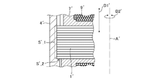
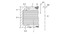
- FIG. 4 is a cross-sectional view taken along the line AA'shown in FIG. 4, showing a first housing, a stator core, and an insulator. It is sectional drawing which follows AA' shown in FIG. 4, and is sectional drawing which shows the insulator. It is explanatory drawing which shows the state which the stator core in the motor for comparison is held by the housing. It is explanatory drawing which shows the state which the stator core in the motor which concerns on Embodiment 1 is held by the 1st housing.
- FIG. 1 is a cross-sectional view showing a main part of the motor according to the first embodiment.
- FIG. 2 is a plan view showing a stator core in the motor according to the first embodiment.
- FIG. 3 is an explanatory diagram showing a state in which the stator core of the motor according to the first embodiment is insert-molded into the first housing.
- FIG. 4 is a plan view showing a state in which an insulator is provided on a stator core in the motor according to the first embodiment.
- FIG. 5 is a cross-sectional view taken along the line AA'shown in FIG. 4, showing a first housing, a stator core, and an insulator.
- FIG. 6 is a cross-sectional view taken along the line AA'shown in FIG. 4, and is a cross-sectional view showing an insulator.
- the motor according to the first embodiment will be described with reference to FIGS. 1 to 6.
- axial direction the direction along the axis A of the motor 100
- machine angle direction the rotation direction with respect to the axis A
- the motor 100 has a stator core 1.
- the stator core 1 is made of, for example, a laminated steel plate.
- the stator core 1 has an annular back yoke portion 2 and has a plurality of teeth portions 3. In the examples shown in FIGS. 1 to 6, the stator core 1 has 12 teeth portions 3.
- the plurality of tooth portions 3 are arranged in the machine angular direction D2 and are arranged at equal intervals.
- the individual teeth portions 3 project to the inner peripheral portion of the back yoke portion 2.
- each tooth portion 3 is integrally molded with the back yoke portion 2.
- each tooth portion 3 is formed in a non-divided manner with the back yoke portion 2.
- the stator core 1 is formed in a non-divided manner with respect to the mechanical angular direction D2.
- the stator core 1 is insert-molded into a housing (hereinafter referred to as "first housing") 4 made of an aluminum alloy. More specifically, a portion including the outer peripheral portion of the back yoke portion 2 is insert-molded in the first housing 4. That is, the first housing 4 holds the stator core 1.
- the first housing 4 is manufactured by casting (for example, die casting). That is, the first housing 4 is a cast product (for example, a die-cast product).
- a plurality of convex portions 5 are provided on the outer peripheral portion of the back yoke portion 2.
- 12 convex portions 5 are provided.
- the plurality of convex portions 5 are arranged in the machine angular direction D2 and are arranged at equal intervals.
- the shape of the outer peripheral portion of the back yoke portion 2 is a gear shape.
- the back yoke portion 2 is provided with a plurality of through-hole-shaped hole portions 6.
- 12 hole portions 6 are provided.
- the plurality of hole portions 6 are arranged in the machine angular direction D2 and are arranged at equal intervals.
- a resin insulator 7 is provided on the stator core 1.
- the resin is contained in each hole 6. This makes it possible to facilitate the positioning of the insulator 7 with respect to the stator core 1. Further, the holding property of the insulator 7 by the stator core 1 can be improved.
- a plurality of notched grooves 8 are provided in the inner peripheral portion of the first housing 4.
- 12 groove portions 8 are provided.
- the plurality of groove portions 8 are arranged in the mechanical angular direction D2 and are arranged at equal intervals.
- the resin is contained in each groove 8. This makes it possible to facilitate the positioning of the insulator 7 with respect to the first housing 4. Further, the holding property of the insulator 7 by the first housing 4 can be improved.
- Winding 9 is provided around each tooth portion 3. However, the resin of the insulator 7 is interposed between the individual teeth portions 3 and the winding 9. That is, when the motor 100 is manufactured, the insulator 7 is provided on the stator core 1, and then the winding 9 is provided on the stator core 1.
- the main part of the stator 10 is composed of the stator core 1, the insulator 7, and the winding 9.
- the motor 100 has an inverter circuit 11 for supplying a current to the stator 10.
- the inverter circuit 11 is held by a housing (hereinafter referred to as "second housing") 12 made of an aluminum alloy.
- the second housing 12 is manufactured by casting (for example, die casting). That is, the second housing 12 is a cast product (for example, a die-cast product).
- the second housing 12 is fixed to the first housing 4 by a plurality of screws (hereinafter referred to as “first screws") 13.
- a sealing material (hereinafter referred to as “first sealing material”) 14 is provided between the first housing 4 and the second housing 12.
- the first sealing material 14 uses, for example, a packing, a gasket, or an O-ring.
- the first sealing material 14 may be in a solid state or a liquid state.
- the second housing 12 may be fixed to the first housing 4 by welding. Alternatively, the second housing 12 may be fixed to the first housing 4 by press fitting. In these cases, the plurality of first screws 13 are unnecessary.
- the rotor 15 is passed through the stator 10. That is, the motor 100 is an inner rotor type.
- the rotor 15 is rotatably supported by a main bearing 16 and an auxiliary bearing 17.
- the auxiliary bearing 17 is held by the first housing 4.
- the main bearing 16 is held by a sheet metal housing (hereinafter referred to as "third housing") 18.
- the third housing 18 is manufactured by a sheet metal press.
- the third housing 18 is fixed to the first housing 4 by a plurality of screws (hereinafter referred to as “second screws") 19.
- a sealing material (hereinafter referred to as “second sealing material”) 20 is provided between the first housing 4 and the third housing 18.
- the second sealing material 20 uses, for example, a packing, a gasket, or an O-ring.
- the second sealing material 20 may be in a solid state or a liquid state.
- the third housing 18 is not limited to the one made of sheet metal.
- the third housing 18 may be made of the same aluminum alloy as the first housing 4 or the second housing 12. That is, the third housing 18 may be a cast product (for example, a die-cast product).
- the same material for example, iron
- the material of the main bearing 16 is used as the material of the third housing 18.
- the difference between the coefficient of linear expansion in the third housing 18 and the coefficient of linear expansion in the main bearing 16 can be reduced.
- the third housing 18 may be fixed to the first housing 4 by welding. Alternatively, the third housing 18 may be fixed to the first housing 4 by press fitting. In these cases, the plurality of second screws 19 are unnecessary.
- first passage 21 a passage for liquid cooling (hereinafter referred to as “first passage") 21 is formed in the first housing 4.
- the first passage 21 includes a U-shaped (that is, U-shaped) portion arranged around the stator 10.
- the stator 10 is cooled by the cooling liquid (hereinafter referred to as “cooling liquid”) flowing in the first passage 21.
- F in FIG. 3 shows the flow of the coolant in the first passage 21.
- the second housing 12 is formed with a passage for liquid cooling (hereinafter referred to as "second passage") 22.
- the second passage 22 communicates with the first passage 21.
- the second passage 22 includes a U-shaped (that is, U-shaped) portion arranged around the inverter circuit 11. The inverter circuit 11 is cooled by the cooling liquid flowing in the second passage 22.
- the motor 100 is used for various purposes. Specifically, for example, the motor 100 is used for an in-vehicle actuator (not shown).
- the actuator is used for opening degree control of an engine valve (not shown). Specifically, for example, the actuator is used for throttle valve opening control, wastegate valve opening control, or EGR valve opening control.
- the motor 100 is used in a high temperature environment and is used in a vibration environment. Therefore, the motor 100 is required to have high cooling performance and high vibration resistance.
- cooling by liquid cooling is realized as described above.
- the cooling performance can be improved due to the following factors.
- the back yoke portion 2 and the individual tooth portions 3 are non-divided. Therefore, inside the stator core 1, there is no interface between the back yoke portion 2 and the individual teeth portions 3. This makes it possible to smoothly transfer heat from the winding 9 to the first housing 4 through the stator core 1 as compared with the case where such an interface is present. As a result, the cooling performance of the stator 10 can be improved as compared with a motor having such an interface (that is, a conventional motor).
- the back yoke portion 2 is insert-molded in the first housing 4. Further, since a plurality of convex portions 5 are formed on the outer peripheral portion of the back yoke portion 2, the contact area between the stator core 1 and the first housing 4 is expanded. As a result, the heat transfer from the winding 9 to the first housing 4 via the stator core 1 can be further smoothed. As a result, the cooling performance of the stator 10 can be further improved.
- the vibration resistance can be improved due to the following factors.
- the back yoke portion 2 is insert-molded into the first housing 4. Further, since a plurality of convex portions 5 are formed on the outer peripheral portion of the back yoke portion 2, the contact area between the stator core 1 and the first housing 4 is expanded. Thereby, the holding property of the stator core 1 by the first housing 4 can be improved. As a result, vibration resistance can be further improved.
- the housing for the inverter circuit 11 (that is, the second housing 12) is composed of a separate member from the housing for the stator 10 (that is, the first housing 4).
- the housing for the rotor 15 (that is, the third housing 18) is composed of a separate member from the housing for the stator 10 (that is, the first housing 4).
- liquid cooling passages (21, 22) are provided in each of the two housings (4, 12), and these passages (21, 22) communicate with each other.
- liquid cooling passages (21, 22) are provided over the two parts (4, 12). This makes it possible to facilitate the manufacture of individual housings (4, 12) by casting with respect to the overall shape of the liquid cooling passages (21, 22). Specifically, for example, the shape of the mold used for manufacturing the individual housings (4, 12) can be simplified.
- stator core 1' is not insert-molded into the housing 4'.
- the stator core 1' is press-fitted into the housing 4'.
- the stator core 1' is adhered to the housing 4'.
- the stator core 1'does not have a plurality of convex portions corresponding to the plurality of convex portions 5.
- A' indicates the axis of the motor 100'.
- the outer peripheral portion of the stator core 1' is in contact with the inner peripheral portion of the housing 4'.
- the stator core 1' since the stator core 1'is press-fitted into the housing 4', friction is generated between the outer peripheral portion of the stator core 1'and the inner peripheral portion of the housing 4'.
- the outer peripheral portion of the stator core 1' is adhered to the inner peripheral portion of the housing 4'. Therefore, a force for holding the stator core 1'is generated in the contact portion S'_1 with respect to the axial direction D1'. Further, in the contact portion S'_1, a force for holding the stator core 1'is generated in the mechanical angular direction D2'.
- a stepped portion is formed on the inner peripheral portion of the housing 4'.
- the stator core 1' is arranged so as to be placed on the stepped surface of the stepped portion (see FIG. 7). That is, the stator core 1 is in contact with the stepped surface. Therefore, a force for holding the stator core 1'is generated in the contact portion S'_2 with respect to the axial direction D1'.
- the stator core 1 is insert-molded into the first housing 4. Further, a plurality of convex portions 5 are provided on the outer peripheral portion of the stator core 1. Therefore, a force for holding the stator core 1 is generated mainly in the contact portion S_1 with respect to the mechanical angular direction D2 (see FIG. 8). Further, in the contact portions S_2 and S_3, a force for holding the stator core 1 is generated with respect to the axial direction D1 (see FIG. 8).
- the stator core 1 is manufactured by punching out an electromagnetic steel sheet and laminating the punched out electromagnetic steel sheet.
- stator core 1 is insert-molded into the first housing 4.
- the insulator 7 is insert-molded on the stator core 1. At this time, the resin of the insulator 7 enters the individual hole portions 6, and the resin of the insulator 7 enters the individual groove portions 8.
- the winding 9 is provided on the stator core 1.
- the stator core 1 is manufactured by punching out an electromagnetic steel sheet and laminating the punched out electromagnetic steel sheet.
- the insulator 7 is manufactured by resin molding.
- the shape of the manufactured insulator 7 includes a portion that enters the individual hole portion 6 and includes a portion that enters the individual groove portion 8.
- stator core 1 is insert-molded into the first housing 4.
- the winding 9 is provided on the stator core 1.
- the first housing 4 and the stator 10 can be manufactured by such a manufacturing method.
- the housing portion of the motor 100 is divided into three parts (4, 12, 18), and the work of providing the winding 9 can be facilitated. That is, when the winding 9 is provided, it is possible to avoid disturbing such work because the second housing 12 and the third housing 18 are not provided.
- the housing portion of the motor 100 is divided into three parts (4, 12, 18), but the motor It is possible to improve the sealing performance in the housing portion of 100. As a result, it is possible to prevent foreign matter from entering the inside of the housing portion of the motor 100.
- the shapes of the individual corners of the first housing 4 and the second housing 12 are right-angled shapes.
- the shape of the individual corners is not limited to the right-angled shape.
- the shape of each corner may be any shape that can be realized by casting.
- the shape of the individual corners may be an R shape.
- the application of the motor 100 is not limited to the actuator for vehicles. Further, the application of the actuator is not limited to the opening control of the engine valve.
- the motor 100 may be used for any purpose as long as it is used in a high temperature environment and a vibration environment.
- the motor 100 holds the stator core 1 having the annular back yoke portion 2 and the plurality of teeth portions 3 protruding from the inner peripheral portions of the back yoke portion 2, and the stator core 1.
- An inner rotor type motor 100 including a first housing 4 made of an aluminum alloy, each tooth portion 3 is integrally molded with a back yoke portion 2, and the back yoke portion 2 is a first casing. It is insert-molded into the body 4, and a first passage 21 for liquid cooling is formed in the first housing 4. With such a structure, the cooling performance can be improved and the vibration resistance can be improved. As a result, the output of the motor 100 can be improved, and the durability of the motor 100 can be improved.
- a resin insulator 7 is provided in the stator core 1, a plurality of groove portions 8 are formed in the first housing 4, and the resin of the insulator 7 is contained in each groove portion 8. This makes it possible to facilitate the positioning of the insulator 7 with respect to the first housing 4. Further, the holding property of the insulator 7 by the first housing 4 can be improved.
- a resin insulator 7 is provided in the stator core 1, a plurality of holes 6 are formed in the back yoke portion 2, and the resin of the insulator 7 is contained in each hole portion 6. This makes it possible to facilitate the positioning of the insulator 7 with respect to the stator core 1. Further, the holding property of the insulator 7 by the stator core 1 can be improved.
- a plurality of convex portions 5 are formed on the outer peripheral portion of the back yoke portion 2. As a result, the contact area between the stator core 1 and the first housing 4 can be expanded. As a result, the cooling performance can be further improved and the vibration resistance can be further improved.
- the motor 100 includes an inverter circuit 11 and a second housing 12 made of an aluminum alloy that holds the inverter circuit 11, and a first sealing material is provided between the first housing 4 and the second housing 12. 14 is provided, the second housing 12 is fixed to the first housing 4, the second passage 22 for liquid cooling is formed in the second housing 12, and the second passage 22 is the second. It communicates with 1 passage 21. Since the housing portion of the motor 100 is divided, the work of providing the winding 9 can be facilitated. Further, by providing the second passage 22 communicating with the first passage 21, the stator 10 can be cooled with the improved cooling capacity, and the inverter circuit 11 can be cooled. can.
- the motor 100 includes a rotor 15 and a main bearing 16, a third housing 18 for holding the rotor 15 and the main bearing 16, and a second housing 18 between the first housing 4 and the third housing 18.
- a sealing material 20 is provided, and the third housing 18 is fixed to the first housing 4. Since the housing portion of the motor 100 is divided, the work of providing the winding 9 can be facilitated. Further, by using the same material (for example, iron) as the material of the main bearing 16 for the material of the third housing 18, the main housing 18 responds to changes in temperature in the environment in which the motor 100 is used. The holding of the bearing 16 can be stabilized.
- the manufacturing method according to the first embodiment is a stator core 1 having a plurality of tooth portions 3 protruding from the annular back yoke portion 2 and the inner peripheral portion of the back yoke portion 2, and an aluminum alloy holding the stator core 1.
- a method for manufacturing an inner rotor type motor 100 including a first housing 4 manufactured by the manufacturer, a resin insulator 7 provided on the stator core 1, and a winding 9 provided around the teeth portion 3.
- a step of insert molding and a step of providing the winding 9 are provided. In this way, the first housing 4 and the stator 10 can be manufactured according to the first specific example.
- the manufacturing method according to the first embodiment is a stator core 1 having a plurality of teeth portions 3 protruding from the annular back yoke portion 2 and the inner peripheral portions of the back yoke portion 2, and an aluminum alloy holding the stator core 1.
- a method for manufacturing an inner rotor type motor 100 including a first housing 4 manufactured by the manufacturer, a resin insulator 7 provided on the stator core 1, and a winding 9 provided around the teeth portion 3.
- the manufacturing method according to the present disclosure can be used for manufacturing a motor.
- the motor according to the present disclosure can be used, for example, for throttle valve opening control, wastegate valve opening control, or EGR valve opening control.
- stator core 1 stator core, 2 back yoke part, 3 teeth part, 4 first housing, 5 convex part, 6 hole part, 7 insulator, 8 groove part, 9 winding, 10 stator, 11 inverter circuit, 12 second housing, 13 1st screw, 14 1st sealing material, 15 rotor, 16 main bearing, 17 auxiliary bearing, 18 3rd housing, 19 2nd screw, 20 2nd sealing material, 21 1st passage, 22 2nd passage, 100 motor ..
Landscapes
- Engineering & Computer Science (AREA)
- Power Engineering (AREA)
- Iron Core Of Rotating Electric Machines (AREA)
- Motor Or Generator Cooling System (AREA)
Priority Applications (2)
| Application Number | Priority Date | Filing Date | Title |
|---|---|---|---|
| JP2022532895A JP7446427B2 (ja) | 2020-06-30 | 2020-06-30 | モータ及び製造方法 |
| PCT/JP2020/025703 WO2022003835A1 (ja) | 2020-06-30 | 2020-06-30 | モータ及び製造方法 |
Applications Claiming Priority (1)
| Application Number | Priority Date | Filing Date | Title |
|---|---|---|---|
| PCT/JP2020/025703 WO2022003835A1 (ja) | 2020-06-30 | 2020-06-30 | モータ及び製造方法 |
Publications (1)
| Publication Number | Publication Date |
|---|---|
| WO2022003835A1 true WO2022003835A1 (ja) | 2022-01-06 |
Family
ID=79314974
Family Applications (1)
| Application Number | Title | Priority Date | Filing Date |
|---|---|---|---|
| PCT/JP2020/025703 Ceased WO2022003835A1 (ja) | 2020-06-30 | 2020-06-30 | モータ及び製造方法 |
Country Status (2)
| Country | Link |
|---|---|
| JP (1) | JP7446427B2 (https=) |
| WO (1) | WO2022003835A1 (https=) |
Citations (4)
| Publication number | Priority date | Publication date | Assignee | Title |
|---|---|---|---|---|
| JPH08237900A (ja) * | 1995-02-27 | 1996-09-13 | Hitachi Ltd | 回転電機 |
| JP2009136130A (ja) * | 2007-10-31 | 2009-06-18 | Mitsuba Corp | ブラシレスモータ |
| JP2012115050A (ja) * | 2010-11-25 | 2012-06-14 | Mitsubishi Electric Corp | 電動機のステータ及びその製造方法 |
| JP2013188030A (ja) * | 2012-03-08 | 2013-09-19 | Mitsubishi Electric Corp | 液冷式回転電機 |
Family Cites Families (1)
| Publication number | Priority date | Publication date | Assignee | Title |
|---|---|---|---|---|
| JP4313086B2 (ja) | 2003-05-19 | 2009-08-12 | 三菱電機株式会社 | 回転機および回転機の製造方法 |
-
2020
- 2020-06-30 WO PCT/JP2020/025703 patent/WO2022003835A1/ja not_active Ceased
- 2020-06-30 JP JP2022532895A patent/JP7446427B2/ja active Active
Patent Citations (4)
| Publication number | Priority date | Publication date | Assignee | Title |
|---|---|---|---|---|
| JPH08237900A (ja) * | 1995-02-27 | 1996-09-13 | Hitachi Ltd | 回転電機 |
| JP2009136130A (ja) * | 2007-10-31 | 2009-06-18 | Mitsuba Corp | ブラシレスモータ |
| JP2012115050A (ja) * | 2010-11-25 | 2012-06-14 | Mitsubishi Electric Corp | 電動機のステータ及びその製造方法 |
| JP2013188030A (ja) * | 2012-03-08 | 2013-09-19 | Mitsubishi Electric Corp | 液冷式回転電機 |
Also Published As
| Publication number | Publication date |
|---|---|
| JP7446427B2 (ja) | 2024-03-08 |
| JPWO2022003835A1 (https=) | 2022-01-06 |
Similar Documents
| Publication | Publication Date | Title |
|---|---|---|
| JP3688898B2 (ja) | 電動機のロータ | |
| EP2719877B1 (en) | Motor rotor structure for electric turbocharger, and method for installing same | |
| US10554092B2 (en) | Rotary electric machine | |
| JP2003070199A (ja) | モータまたは発電機及びその製造方法 | |
| US11867309B2 (en) | Throttle valve device and method for magnetizing the same | |
| US11092086B2 (en) | Throttle valve device | |
| JP2018157644A (ja) | モータユニット | |
| US11092087B2 (en) | Throttle valve device | |
| WO2016174711A1 (ja) | 回転電機 | |
| JP2008167609A (ja) | 電動機 | |
| JP2009148115A (ja) | モータ | |
| WO2022003835A1 (ja) | モータ及び製造方法 | |
| JP2019134567A (ja) | 回転電機のステータ | |
| CN112483547A (zh) | 混合式磁悬浮径向轴承、包含其的设备以及装配方法 | |
| JP2009213218A (ja) | 回転電機の冷却構造およびその製造方法 | |
| JP2004040924A (ja) | 回転電機の冷却構造 | |
| JP5402001B2 (ja) | 回転電機の冷却構造およびその製造方法 | |
| JP7371790B2 (ja) | 固定子 | |
| JPWO2016047310A1 (ja) | 回転電機 | |
| JP7328526B2 (ja) | 絞り弁装置 | |
| KR102481461B1 (ko) | 전기자동차용 모터 하우징 및 그 제조방법 | |
| JP7504320B1 (ja) | モータ | |
| CN222127731U (zh) | 转子组件和电子水泵 | |
| CN221978740U (zh) | 一种油冷电机 | |
| JPWO2022003835A5 (https=) |
Legal Events
| Date | Code | Title | Description |
|---|---|---|---|
| 121 | Ep: the epo has been informed by wipo that ep was designated in this application |
Ref document number: 20943631 Country of ref document: EP Kind code of ref document: A1 |
|
| ENP | Entry into the national phase |
Ref document number: 2022532895 Country of ref document: JP Kind code of ref document: A |
|
| NENP | Non-entry into the national phase |
Ref country code: DE |
|
| 122 | Ep: pct application non-entry in european phase |
Ref document number: 20943631 Country of ref document: EP Kind code of ref document: A1 |