WO2021261404A1 - 表示媒体、表示支援媒体、処理装置、プログラムおよびプログラムを記録したコンピュータ読み取り可能な記録媒体 - Google Patents
表示媒体、表示支援媒体、処理装置、プログラムおよびプログラムを記録したコンピュータ読み取り可能な記録媒体 Download PDFInfo
- Publication number
- WO2021261404A1 WO2021261404A1 PCT/JP2021/023236 JP2021023236W WO2021261404A1 WO 2021261404 A1 WO2021261404 A1 WO 2021261404A1 JP 2021023236 W JP2021023236 W JP 2021023236W WO 2021261404 A1 WO2021261404 A1 WO 2021261404A1
- Authority
- WO
- WIPO (PCT)
- Prior art keywords
- color
- display
- projecting member
- colors
- medium
- Prior art date
- Legal status (The legal status is an assumption and is not a legal conclusion. Google has not performed a legal analysis and makes no representation as to the accuracy of the status listed.)
- Ceased
Links
Images


Classifications
-
- G—PHYSICS
- G02—OPTICS
- G02F—OPTICAL DEVICES OR ARRANGEMENTS FOR THE CONTROL OF LIGHT BY MODIFICATION OF THE OPTICAL PROPERTIES OF THE MEDIA OF THE ELEMENTS INVOLVED THEREIN; NON-LINEAR OPTICS; FREQUENCY-CHANGING OF LIGHT; OPTICAL LOGIC ELEMENTS; OPTICAL ANALOGUE/DIGITAL CONVERTERS
- G02F1/00—Devices or arrangements for the control of the intensity, colour, phase, polarisation or direction of light arriving from an independent light source, e.g. switching, gating or modulating; Non-linear optics
- G02F1/01—Devices or arrangements for the control of the intensity, colour, phase, polarisation or direction of light arriving from an independent light source, e.g. switching, gating or modulating; Non-linear optics for the control of the intensity, phase, polarisation or colour
- G02F1/13—Devices or arrangements for the control of the intensity, colour, phase, polarisation or direction of light arriving from an independent light source, e.g. switching, gating or modulating; Non-linear optics for the control of the intensity, phase, polarisation or colour based on liquid crystals, e.g. single liquid crystal display cells
- G02F1/1323—Arrangements for providing a switchable viewing angle
-
- G—PHYSICS
- G09—EDUCATION; CRYPTOGRAPHY; DISPLAY; ADVERTISING; SEALS
- G09F—DISPLAYING; ADVERTISING; SIGNS; LABELS OR NAME-PLATES; SEALS
- G09F19/00—Advertising or display means not otherwise provided for
- G09F19/12—Advertising or display means not otherwise provided for using special optical effects
- G09F19/14—Advertising or display means not otherwise provided for using special optical effects displaying different signs depending upon the view-point of the observer
-
- G—PHYSICS
- G02—OPTICS
- G02F—OPTICAL DEVICES OR ARRANGEMENTS FOR THE CONTROL OF LIGHT BY MODIFICATION OF THE OPTICAL PROPERTIES OF THE MEDIA OF THE ELEMENTS INVOLVED THEREIN; NON-LINEAR OPTICS; FREQUENCY-CHANGING OF LIGHT; OPTICAL LOGIC ELEMENTS; OPTICAL ANALOGUE/DIGITAL CONVERTERS
- G02F1/00—Devices or arrangements for the control of the intensity, colour, phase, polarisation or direction of light arriving from an independent light source, e.g. switching, gating or modulating; Non-linear optics
- G02F1/01—Devices or arrangements for the control of the intensity, colour, phase, polarisation or direction of light arriving from an independent light source, e.g. switching, gating or modulating; Non-linear optics for the control of the intensity, phase, polarisation or colour
- G02F1/13—Devices or arrangements for the control of the intensity, colour, phase, polarisation or direction of light arriving from an independent light source, e.g. switching, gating or modulating; Non-linear optics for the control of the intensity, phase, polarisation or colour based on liquid crystals, e.g. single liquid crystal display cells
- G02F1/133—Constructional arrangements; Operation of liquid crystal cells; Circuit arrangements
- G02F1/1333—Constructional arrangements; Manufacturing methods
- G02F1/1335—Structural association of cells with optical devices, e.g. polarisers or reflectors
- G02F1/133509—Filters, e.g. light shielding masks
- G02F1/133512—Light shielding layers, e.g. black matrix
-
- G—PHYSICS
- G02—OPTICS
- G02F—OPTICAL DEVICES OR ARRANGEMENTS FOR THE CONTROL OF LIGHT BY MODIFICATION OF THE OPTICAL PROPERTIES OF THE MEDIA OF THE ELEMENTS INVOLVED THEREIN; NON-LINEAR OPTICS; FREQUENCY-CHANGING OF LIGHT; OPTICAL LOGIC ELEMENTS; OPTICAL ANALOGUE/DIGITAL CONVERTERS
- G02F1/00—Devices or arrangements for the control of the intensity, colour, phase, polarisation or direction of light arriving from an independent light source, e.g. switching, gating or modulating; Non-linear optics
- G02F1/01—Devices or arrangements for the control of the intensity, colour, phase, polarisation or direction of light arriving from an independent light source, e.g. switching, gating or modulating; Non-linear optics for the control of the intensity, phase, polarisation or colour
- G02F1/13—Devices or arrangements for the control of the intensity, colour, phase, polarisation or direction of light arriving from an independent light source, e.g. switching, gating or modulating; Non-linear optics for the control of the intensity, phase, polarisation or colour based on liquid crystals, e.g. single liquid crystal display cells
- G02F1/133—Constructional arrangements; Operation of liquid crystal cells; Circuit arrangements
- G02F1/1333—Constructional arrangements; Manufacturing methods
- G02F1/1335—Structural association of cells with optical devices, e.g. polarisers or reflectors
- G02F1/133553—Reflecting elements
-
- G—PHYSICS
- G02—OPTICS
- G02F—OPTICAL DEVICES OR ARRANGEMENTS FOR THE CONTROL OF LIGHT BY MODIFICATION OF THE OPTICAL PROPERTIES OF THE MEDIA OF THE ELEMENTS INVOLVED THEREIN; NON-LINEAR OPTICS; FREQUENCY-CHANGING OF LIGHT; OPTICAL LOGIC ELEMENTS; OPTICAL ANALOGUE/DIGITAL CONVERTERS
- G02F1/00—Devices or arrangements for the control of the intensity, colour, phase, polarisation or direction of light arriving from an independent light source, e.g. switching, gating or modulating; Non-linear optics
- G02F1/01—Devices or arrangements for the control of the intensity, colour, phase, polarisation or direction of light arriving from an independent light source, e.g. switching, gating or modulating; Non-linear optics for the control of the intensity, phase, polarisation or colour
- G02F1/13—Devices or arrangements for the control of the intensity, colour, phase, polarisation or direction of light arriving from an independent light source, e.g. switching, gating or modulating; Non-linear optics for the control of the intensity, phase, polarisation or colour based on liquid crystals, e.g. single liquid crystal display cells
- G02F1/133—Constructional arrangements; Operation of liquid crystal cells; Circuit arrangements
- G02F1/1333—Constructional arrangements; Manufacturing methods
- G02F1/1335—Structural association of cells with optical devices, e.g. polarisers or reflectors
- G02F1/133509—Filters, e.g. light shielding masks
- G02F1/133514—Colour filters
-
- G—PHYSICS
- G02—OPTICS
- G02F—OPTICAL DEVICES OR ARRANGEMENTS FOR THE CONTROL OF LIGHT BY MODIFICATION OF THE OPTICAL PROPERTIES OF THE MEDIA OF THE ELEMENTS INVOLVED THEREIN; NON-LINEAR OPTICS; FREQUENCY-CHANGING OF LIGHT; OPTICAL LOGIC ELEMENTS; OPTICAL ANALOGUE/DIGITAL CONVERTERS
- G02F1/00—Devices or arrangements for the control of the intensity, colour, phase, polarisation or direction of light arriving from an independent light source, e.g. switching, gating or modulating; Non-linear optics
- G02F1/01—Devices or arrangements for the control of the intensity, colour, phase, polarisation or direction of light arriving from an independent light source, e.g. switching, gating or modulating; Non-linear optics for the control of the intensity, phase, polarisation or colour
- G02F1/13—Devices or arrangements for the control of the intensity, colour, phase, polarisation or direction of light arriving from an independent light source, e.g. switching, gating or modulating; Non-linear optics for the control of the intensity, phase, polarisation or colour based on liquid crystals, e.g. single liquid crystal display cells
- G02F1/133—Constructional arrangements; Operation of liquid crystal cells; Circuit arrangements
- G02F1/1333—Constructional arrangements; Manufacturing methods
- G02F1/1335—Structural association of cells with optical devices, e.g. polarisers or reflectors
- G02F1/13356—Structural association of cells with optical devices, e.g. polarisers or reflectors characterised by the placement of the optical elements
- G02F1/133562—Structural association of cells with optical devices, e.g. polarisers or reflectors characterised by the placement of the optical elements on the viewer side
Definitions
- the present invention relates to a display medium, a display support medium, a processing device, a program, and a computer-readable recording medium on which the program is recorded.
- a medium see Patent Document 1.
- the display medium displays different contents in a plurality of designated directions.
- the color of the projecting member is a single color.
- the color of the content displayed by the display medium may be affected by the color of the projecting member.
- the color of the content displayed by the display medium is blackish, and when the projecting member is red, the color of the content is reddish. If the color of the content and the color of the projecting member match, the color of the projecting member does not significantly affect the visibility of the displayed content. In order to improve the visibility of the content, it is necessary that there is no big difference in the color of each content displayed in each direction, which limits the selection of the content.
- an object of the present invention is to provide a display medium, a display support medium, a processing device, a program, and a computer-readable recording medium on which the program is recorded, which are in harmony with any content.
- the display medium of one aspect of the present invention is a display medium capable of displaying a predetermined number of contents corresponding to a predetermined number of azimuths from a predetermined elevation angle and azimuth angle, and emits light. It is provided with a reflective flat member, the flat member is divided into a plurality of unit cells, each of the plurality of unit cells is divided into a predetermined number of subcells corresponding to a predetermined number of azimuths, and each subcell corresponding to a predetermined azimuth angle is provided.
- a projecting member having a surface that shields light and parallel to a predetermined azimuth on the planar member is formed perpendicular to the planar member, and the projecting member is a plurality of colors forming an achromatic color by additive color mixing. Be colored.
- the upper surface of the projecting member is divided into a plurality of regions to which each color is given, and different colors are given to the regions adjacent to each other in the vertical and horizontal directions, and the regions are adjacent to each other in the diagonal direction.
- the areas may be given the same color.
- the plurality of colors colored on the projecting member may be the primary colors of the ink used in the inkjet printing machine.
- the region may be formed by a plurality of injections by an inkjet printing machine.
- the display medium of one aspect of the present invention is a display medium capable of displaying a predetermined number of contents corresponding to a predetermined number of azimuths from a predetermined elevation angle and azimuth angle, and is provided with a flat member that reflects light and is flat.
- the member is divided into a plurality of unit cells, each of the plurality of unit cells is divided into a predetermined number of subcells corresponding to a predetermined number of azimuths, and each subcell corresponding to a predetermined azimuth is flattened to a predetermined azimuth angle.
- a projecting member having a surface that is parallel to the member and shields light is formed perpendicular to the planar member, and the projecting member is formed in gray.
- the display support medium of one aspect of the present invention can be attached to a display surface having a plane that reflects light, and can display a predetermined number of contents corresponding to a predetermined number of azimuths from a predetermined elevation angle and azimuth angle.
- each subcell corresponding to a predetermined azimuth is formed with a projecting member having a light-shielding surface parallel to the sheet-like member at a predetermined azimuth and perpendicular to the sheet-like member.
- the protruding member is colored with a plurality of colors forming an achromatic color by additive color mixing.
- the display support medium of one aspect of the present invention can be attached to a display surface having a plane that reflects light, and can display a predetermined number of contents corresponding to a predetermined number of azimuths from a predetermined elevation angle and azimuth angle.
- each subcell corresponding to a predetermined azimuth is formed with a projecting member having a light-shielding surface parallel to the sheet-shaped member at a predetermined azimuth angle and perpendicular to the sheet-shaped member.
- the protruding member is formed in gray.
- the processing apparatus of one aspect of the present invention is a processing apparatus used for manufacturing the display medium or the display support medium, and is a color determination that determines a color combination in which a protruding member forms an achromatic color by additive mixing. It has a part.
- the processing apparatus is a processing apparatus used for manufacturing the display medium or the display support medium, and is a color that forms an achromatic color by additive mixing so that the protruding member looks achromatic. It is provided with an arrangement determination unit for determining the arrangement of.
- the processing program of one aspect of the present invention is a processing program for causing a computer to function as the above-mentioned processing apparatus.
- a display medium a display support medium, a processing device, a program, and a computer-readable recording medium on which the program is recorded, which are in harmony with any content.
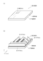
- FIG. 1 (a) is a perspective view of a display medium according to an embodiment of the present invention
- FIG. 1 (b) is a perspective view of a unit cell.
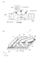
- FIG. 2 is a diagram illustrating a relationship between an azimuth for observing content on a display medium and a protruding member.
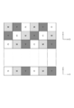
- FIG. 3 is an example of the colors assigned to the projecting members in the top view of the display medium.
- FIG. 4 is an example of the color assigned to the projecting member in the top view of the display medium.
- FIG. 4A shows the area having a small particle size
- FIG. 4B shows the area having a medium particle size.
- FIG. 4C the particle size of the region is large.
- FIG. 5 is a diagram illustrating a display support medium according to the third embodiment.
- FIG. 5 is a diagram illustrating a display support medium according to the third embodiment.
- FIG. 6 is a diagram illustrating a hardware configuration and a functional block of a processing device used for forming a display medium or a display support medium according to an embodiment of the present invention.
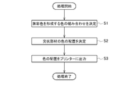
- FIG. 7 is a flowchart illustrating a process according to an embodiment of the present invention.
- the display medium 1 according to the embodiment of the present invention will be described with reference to FIG.
- the display medium 1 according to the embodiment of the present invention is formed so as to be able to display a predetermined number of contents corresponding to a predetermined number of azimuth angles from a predetermined elevation angle and azimuth angle.
- the display medium 1 can display contents by observing from a predetermined elevation angle at a predetermined azimuth angle, and can display different contents by changing the azimuth angle.
- the display medium 1 can display a plurality of contents for each predetermined azimuth angle. Further, the elevation angle when the observer observes the content may be different for each content.
- the content is a still image.
- the direction in which the display medium 1 displays the content may be referred to as a designated direction.
- the display medium 1 is provided with a coloring portion 4 on the flat surface of the flat surface member 2.
- the plane member 2 has a plane that reflects light.
- the flat member 2 may be any as long as it can be specularly reflected or diffused. Further, the flat member 2 is preferably formed of a metal having a high mirror surface component from the viewpoint of improving visibility.
- the colored portion 4 is a portion colored with ink.
- the plane of the plane member 2 is divided into a plurality of unit cells C.
- the plane of the plane member 2 has a plurality of unit cells arranged in the vertical direction and the horizontal direction, respectively.
- each of the plurality of unit cells C is divided into a predetermined number of subcells B corresponding to a predetermined number of azimuth angles.
- the unit cell C and the subcell B may be virtual divisions. For example, if the same color value is given to two adjacent subcells B, or depending on the arrangement of the projecting member 3, the boundary between the subcells B or the unit cell C may not be visible.
- the plane member 2 is a rectangular parallelepiped in the example shown in FIG. 1
- the plane member 2 has a plane and the coloring portion 4 is provided on the plane.
- the unit cell C and the subcell B are each rectangular will be described, but the shapes of the unit cell C and the subcell B are not limited.
- the number of subcells B in one unit cell C corresponds to the number of contents that can be displayed on the display medium 1. For example, in the example shown in FIG. 1, since one unit cell C is divided into three subcells B, it is possible to display at least three contents.
- Each subcell B corresponding to a predetermined azimuth angle of the coloring unit 4 is given a color of each portion corresponding to the position of each subcell B constituting the content corresponding to the predetermined azimuth angle.
- a plate-shaped projecting member 3 is arranged perpendicular to the flat member 2.
- the case where two projecting members 3 are provided in each subcell B is described, but one projecting member 3 may be provided in each subcell B, or three.
- the above protruding member 3 may be provided.
- the projecting member 3 has a surface that is parallel on the flat member 2 and shields light with respect to each of a predetermined number of azimuth angles.
- the projecting member 3 is preferably formed of an opaque member that shields light, but may be formed so that a part of light is transmitted within a range that does not affect the visibility of the observer.
- a protruding member 3 having a surface parallel to the predetermined azimuth angle is formed.
- the projecting members 3 When a plurality of projecting members 3 are provided in one subcell B, the projecting members 3 are arranged in parallel with each other.
- the projecting members 3 are arranged in different directions for each subcell B in which the projecting members 3 are provided, and the projecting members 3 disposed in the different subcells B are arranged so as not to be parallel to each other. ..
- the display medium 1 according to the embodiment of the present invention is observed at a predetermined elevation angle. As shown in FIG. 1 (b), since the plate-shaped projecting member 3 is vertically provided on the plane of the flat surface member 2, the display medium 1 is shielded by the projecting member 3 when the display medium 1 is observed from a predetermined elevation angle. The colored portion 4 that is not formed is confirmed.
- the area ratio of each subcell B in the unit cell C and the shape of the projecting member 3 are (1) the amount of light shielding by the projecting member 3 with respect to the light of the predetermined subcell B viewed from a predetermined azimuth angle, and (1). 2) At least one of (1) to (3) with respect to the amount of light from a direction other than the predetermined direction or the subcell B other than the predetermined subcell B and (3) the standard deviation of the reflected brightness of each subcell B. Is formed so that there is less.
- the shapes of each subcell B and the projecting member 3 are specified by the method described in Patent Document 1.
- FIG. 2A describes a case where the contents I0, I1 and I2 are displayed on the display medium 1.
- the color values of the coordinates of the content I0 corresponding to the coordinates x on the display medium 1 can be confirmed.
- the coordinates x on the display medium 1 are observed at a predetermined elevation angle ⁇ 1 and an azimuth angle ⁇ 1
- the color values of the coordinates of the content I1 corresponding to the coordinates x on the display medium 1 can be confirmed.
- the coordinates x on the display medium 1 are observed at a predetermined elevation angle ⁇ 2 and an azimuth angle ⁇ 2
- the color values of the coordinates of the content I2 corresponding to the coordinates x on the display medium 1 can be confirmed.
- the unit cell C of the display medium 1 shown in FIG. 1 (a) is formed as shown in FIG. 2 (b), for example.
- the unit cell C includes a subcell B0, a subcell B1 and a subcell B2.
- the subcell B0 three projecting members L0 parallel to the direction of the azimuth angle ⁇ 0 are arranged.
- the subcell B1 two projecting members L1 parallel to the direction of the azimuth angle ⁇ 1 are arranged.
- three projecting members L2 parallel to the direction of the azimuth angle ⁇ 2 are arranged.
- the unit cell C when the unit cell C is observed from the direction of the azimuth angle ⁇ 0, the color of the colored portion 4 of the subcell B0 can be seen, and the protruding members L0 and the subcells B1 arranged in the subcell B0 can be seen.
- the protruding member L1 and the protruding member L2 arranged in the subcell B2 can be seen. Since the projecting member L0 arranged in the subcell B0 is formed in parallel with the azimuth angle ⁇ 0, the thick portion of the projecting member L0 is observed, so that the color of the projecting member L0 gives the visibility of the content. The impact may be limited.
- the projecting member L1 arranged in the subcell B1 and the projecting member L2 arranged in the subcell B2 are formed so that the longitudinal direction intersects the azimuth angle ⁇ 0, so that the subcell B1 and the subcell B2 are arranged in a wide surface.
- the color of the colored portion 4 of the above is shielded.
- the color of the wide surface of the projecting member L1 and the projecting member L2 has a great influence on the visibility of the content.
- the projecting member 3 is formed of gray, which is an achromatic color.
- the projecting member 3 may be formed of a gray member, or may be formed by coloring a member having a color other than gray with gray.
- the first embodiment is suitable for the display medium 1 in which the gray member can be formed as the projecting member 3.
- the achromatic color is gray excluding white and black.
- the projecting member 3 may be colored with a plurality of colors forming an achromatic color by additive mixing, or may be formed by connecting members formed of the plurality of colors. For example, when viewed from a position facing the plane member 2, the upper surface of the projecting member is divided into a plurality of regions to which each color is given, and different colors are given to the regions adjacent to each other in the vertical and horizontal directions, and the diagonal direction is obtained. Colored so that the adjacent areas are given the same color. When observing the projecting member 3 at a close distance, even if each color can be confirmed separately, when the content displayed by the display medium 1 is observed from a distant place where it can be visually recognized, it is gray due to additive color, specifically. It is good if the color looks brighter than black.
- the display medium 1 can be harmonized with any content without limiting the color of the content.
- the projecting member 3 may be formed in gray by irradiating the projecting member 3 with a plurality of colors in an overlapping manner by simultaneous addition color mixing.
- the coloring of the projecting member 3 can be changed by time division, it may be formed so as to be recognized as gray in the human brain by time-sharing additive color mixing.
- the inkjet printing machine scans on the flat surface member 2 to color the colored portion 4 and forms the projecting member 3.
- the inkjet printing machine colors the colored portion 4 according to the color value given to each subcell calculated by the method described in Patent Document 1.
- the coloring portion 4 is formed by the color of the ink mounted on the inkjet printing machine or the color mixed with the ink.
- the inkjet printing machine injects UV resin at the position of the projecting member 3 so as to have a desired height.
- the UV resin is cured, a fine uneven shape of the projecting member 3 is formed on the flat member 2.
- the inkjet printing machine forms the projecting member 3 so as to have a light-shielding property, for example, to have a thickness of 0.005 mm or more.
- the inkjet printing machine mixes UV ink and gray ink to form the projecting member 3.
- the display medium 1 that can be harmonized with any content without limiting the color of the content.
- Half toning and contouring are methods for forming a neutral color such as gray that is different from the color of the ink mounted on the inkjet printing machine. Since half toning is expressed by dither pattern or error diffusion, it cannot be used for a protruding member in principle. In the contouring, when the colors are controlled by superimposing them, the height may differ depending on the neutral color, and it is not possible to form a projecting member having a uniform height. Therefore, it is not possible to form the projecting member 3 by a method in which a printer generally forms a neutral color.
- the projecting member 3 is colored with a plurality of colors forming an achromatic color by additive color mixing.
- each color applied to the protruding member 3 can be confirmed at a close position, but the color of the protruding member 3 is achromatic at a position visible by additive color mixing.
- the color is brighter than black. As a result, the color of the projecting member 3 does not affect the hue of the color of the content.
- the plurality of colors colored on the projecting member 3 are the primary colors of the ink used in the inkjet printing machine.
- Each color constituting the plurality of colors may be the color of the ink mounted on the inkjet printing machine.
- the colors constituting the plurality of colors may be a combination of other colors such as RGB.
- the height of the projecting member 3 is made uniform, and the projecting shape accompanying the color mixing is further performed. It is possible to avoid a decrease in the brightness of the member 3.
- the inkjet printing machine independently injects each ink to be mounted on each adjacent minute area without mixing them.
- each color of CMY can be distinguished at a close distance where the colors of each ink can be distinguished and visually recognized
- the CMY becomes mixed gray at a distant position where additive color mixing is possible.
- the display medium 1 does not limit the color of the content, and any content can be used. Can be in harmony with.
- the projecting member 3 may be formed in gray by irradiating the projecting member 3 with a plurality of colors in an overlapping manner by simultaneous addition color mixing.
- the coloring of the projecting member 3 can be changed by time division, it may be formed so as to be recognized as gray in the human brain by time-sharing additive color mixing.
- the upper surface of the projecting member 3 is divided into a plurality of regions to which each color is given, and each region is given each color of CMY.
- the upper surface of each protruding member 3 provided in each cell is divided into a plurality of regions, and each region is colored with the color of the ink mounted on the inkjet printing machine.
- the region divided on the upper surface of the projecting member 3 may have the same unit cell C or may be different. For example, one color may be given in the unit cell C, one color may be given over a plurality of unit cells C, or a plurality of colors may be given in one unit cell C.
- each color of CMY it is sufficient that the protruding member 3 looks gray due to additive mixing when displaying the content, and the arrangement of each color of CMY is not limited.
- the Y-axis direction is divided into a plurality of regions without dividing the X-axis direction of the projecting member 3, so that the X-axis direction is the longitudinal direction. Multiple regions of are formed in the Y-axis direction.
- Each of the plurality of areas is colored with any color of CMY.
- the color given on the upper surface of the projecting member 3 is colored perpendicularly to the plane member 2 in the Z-axis direction.
- the X-axis direction of the projecting member 3 is divided into a plurality of regions and the Y-axis direction is not set, so that the Y-axis direction is a plurality of longitudinal directions.
- the region is formed in the X-axis direction.
- Each of the plurality of areas is colored with any color of CMY.
- the color given on the upper surface of the projecting member 3 is colored perpendicularly to the plane member 2 in the Z-axis direction. Specifically, in the example shown in FIG.
- any color of CMY is colored on one surface, and the cell is colored from the front side in the Y-axis direction.
- the side surface of the projecting member 3 is colored in a vertical stripe shape in the order of CMY.
- the projecting member 3 There is also a method of dividing the projecting member 3 into diagonal stripe shapes in the top view and coloring each color of CMY.
- the X-axis direction and the Y-axis direction of the projecting member 3 are divided into a plurality of regions, and the regions are formed diagonally to form an oblique region.
- a plurality of regions in the longitudinal direction are formed in the XY plane.
- Each of the plurality of areas is colored with any color of CMY.
- the color given on the upper surface of the projecting member 3 is colored perpendicularly to the plane member 2 in the Z-axis direction. Specifically, in the example shown in FIG.
- FIGS. 1 (b) and 2 (b) There is also a method of dividing the projecting member 3 into grid-like regions in a top view and coloring each color of CMY.
- a plurality of rectangles are arranged in a grid pattern by dividing the X-axis direction and the Y-axis direction of the projecting member 3 into a plurality of regions. Form multiple regions.
- the color given on the upper surface of the projecting member 3 is colored perpendicular to the Z-axis direction up to the colored portion 4. Specifically, in the example shown in FIG.
- the projecting members 3 are given different colors to the regions adjacent to each other in the vertical direction and the horizontal direction, and the same color is given to the regions adjacent to each other in the oblique direction in the top view. ..
- the upper figure of FIG. 3 shows a color pattern given to the projecting member 3 in a top view of the display medium 1.
- the figure below shows a color pattern given to the projecting member 3 in a side view of the display medium 1.
- white indicates cyan (C)
- light gray indicates magenta (M)
- dark gray indicates yellow (Y).
- the regions of each color of CMY are arranged diagonally in the 45-degree direction, and CMY is repeatedly arranged in both the X-axis direction and the Y-axis direction.
- the CMY is arranged adjacent to the surrounding rectangle. Therefore, when the display medium 1 is confirmed from the position where additive color mixing occurs, the achromatic color becomes uniform. It is formed.
- the pattern as shown in FIG. 3 does not depend on the direction of the projecting member 3, in other words, the direction in which the display medium 1 displays the content, and thus can be applied to any display medium 1.
- one region that divides the upper surface of the projecting member 3 in the top view is formed by a plurality of injections by an inkjet printing machine.
- UV curable ink is a liquid until it is cured, so when only one dot is struck alone, it tends to spread and may not be able to form a desired height. Further, in general, when inks of different colors are struck next to each other, they are mixed and the color becomes muddy, so that the color cannot be controlled in dot units.
- the dots are printing surfaces formed by one injection by an inkjet printing machine.
- each region is formed by a plurality of dots, it is possible to prevent the UV curable ink from spreading and the colors from being mixed, and to form the projecting member 3 having a desired color and a desired height.
- each area by forming each area with a plurality of dots, it is conceivable that color mixing may occur at the boundary portion of different colors, but it is possible to secure the dot portion where the color mixing does not occur.
- the two dots at both ends are adjacent to the regions to which different colors are given, so that color mixing occurs, but the other 8 With dots, color mixing is unlikely to occur.
- color mixing occurs in a portion where different colors are adjacent to each other, color mixing does not occur in a portion where the same color is adjacent to each other, so that reduction in brightness due to color mixing can be suppressed.
- the number of dots constituting each region is determined so that the effect that the UV effect ink does not spread and the colors are not mixed and the effect that the color in the surrounding region and the additive color are additively mixed can be compatible with each other. ..
- the present invention is not limited to this.
- the display medium 1 is referred to from each position where the content displayed by the display medium 1 is visually recognized, the projecting member 3 may be achromatic, and the colors do not have to be the same. It is preferable that the projecting member 3 is colored without leakage with any of the inks mounted on the inkjet printing machine, and each color has the same area. Further, although the case where the color combination forming the achromatic color is the three colors of CMY has been described, the combination of four or more primary colors of the ink mounted on the inkjet printing machine may be used.
- FIG. 4 An example in which the projecting member 3 is colored will be described with reference to FIG.
- unit cells C are arranged in a size of 5 ⁇ 5, and a T-shaped projecting member 3 is formed in each cell.
- the particle size of the region (rectangle) formed on the upper surface of the projecting member 3 gradually increases in the order of FIGS. 4 (a), 4 (b), and 4 (c).
- a region of the same color is provided in the diagonal 45-degree direction in the top view.
- the coarser the grain size of each region the easier it is to see the shadow in the same color direction of the region, and the finer the particle size, the harder it is to see the shadow in the same color direction of the region.
- the particle size of each area may be determined by the content or the like displayed by the display medium 1.
- the display medium 1 according to the second embodiment has improved visibility of the content as compared with the display medium in which the protruding member 3 is formed of black.
- the first embodiment and the second embodiment have described the case where the display medium 1 provided with the colored portion 4 and the achromatic member 3 on the flat surface member 2 is formed, but other embodiments are described. It can be realized in an embodiment.
- the display support medium 11 in which the protruding member 3 described above is formed on the sheet-shaped member having a sheet shape and transmitting light reflects light. It is attached to the display surface 13 of the general display device 12 to be used.
- the display device 12 displays an image in which the color of each subcell is determined according to the shapes of the unit cell C, the subcell B, and the projecting member 3 formed by the display support medium 11. In other words, the display device 12 electrically realizes the coloring unit 4 according to the first embodiment and the second embodiment.
- the sheet-shaped member used for the display support medium 11 is preferably formed of a transparent member that transmits light, but is formed so that a part of light is transmitted within a range that does not affect the visibility of the observer. May be done.
- the display device 12 is preferably a liquid crystal display, an organic EL display, or the like, and is a display that uses a bright backlight or a bright light emitting element.
- the display support medium 11 according to the third embodiment is suitable when it is desired to display an arbitrary different image depending on the azimuth angle.
- the display support medium 11 displays, for example, information according to the position of each observer and other conditions to a plurality of observers who observe the display support medium 11 attached to the display device 12 from different directions. Is possible.
- the protruding member 3 formed on the sheet-shaped member may be formed in gray as described in the first embodiment or the second embodiment, or may be additive. It may be colored with a plurality of colors that form an achromatic color by mixing colors.
- the plurality of colors colored on the projecting member 3 are each of the inkjet printing machine. It is preferable that it is the primary color of the ink used in.
- the upper surface of the projecting member 3 is divided into a plurality of regions to which each color is given, and different colors are given to the regions adjacent to each other in the vertical direction and the horizontal direction, and the diagonal direction is obtained. It is preferable that the same color is given to the regions adjacent to each other. Further, these regions are preferably formed by a plurality of injections by an inkjet printing machine.
- the display device 12 can display an arbitrary image, it is possible to appropriately display an image according to an arbitrary condition. Further, by continuously changing the image by the display device 12, it is possible to observe different moving image contents from each azimuth angle.
- a display support medium 11 having a protruding member 3 formed of a plurality of colors formed in gray or achromatic color formed by additive color mixing is attached to such a display device 12, thereby supporting display.
- the medium 11 can be harmonized with any content without affecting the hue of the content displayed by the display device 12.
- the display support medium 11 Since the pixels of the image displayed by the display device 12 correspond to the subcells formed on the display support medium 11, the display support medium 11 is appropriately aligned so that the display support medium 11 is appropriately attached to the display surface 13. ..
- the processing apparatus 100 is a general computer including a storage device 110, a processing control device 120, and an input / output interface 130.
- the function shown in FIG. 6 is realized by executing a processing program by a general computer.
- the processing apparatus 100 shown in FIG. 6 determines a color combination or a color arrangement when coloring the projecting member 3 by additive color mixing by combining a plurality of colors.
- the processing device 100 is used by the inkjet printing machine to manufacture the display support medium 11 according to the display medium 1 according to the second embodiment or the display support medium 11 according to the third embodiment.
- the storage device 110 is a ROM (Read Only Memory), a RAM (Random access memory), a hard disk, an SSD (Solid State Drive), or the like, and is an input data, an output data, and an intermediate for the processing control device 120 to execute processing. Stores various data such as data.
- the processing control device 120 is a CPU (Central Processing Unit) that reads and writes data stored in the storage device 110 and inputs / outputs data to / from the input / output interface 130 to execute processing in the processing device 100. do.
- the input / output interface 130 inputs the processing result of the processing device 100 to the inkjet printing machine.
- the inkjet printing machine forms the projecting member 3 of the display medium 1 with reference to the result obtained from the processing device 100.
- the storage device 110 stores the processing program and also stores the color data 111 and the arrangement data 112.
- the color data 111 is a color determined by the color determining unit 121, and is data for specifying a combination of colors forming an achromatic color by additive mixing.
- the arrangement data 112 is the arrangement of colors determined by the arrangement determination unit 122, and is data for specifying the size of a region in which the same color is arranged and the arrangement of colors forming an achromatic color by additive mixing.
- the processing program can be stored in a computer-readable recording medium such as HDD, SSD, USB (Universal Serial Bus) memory, CD (Compact Disc), DVD (Digital Versatile Disc), or distributed via a network. can.
- the processing control device 120 includes a color determination unit 121, an arrangement determination unit 122, and an output unit 123.
- the color determination unit 121 determines a color combination in which the protruding member 3 forms an achromatic color by additive mixing. For example, when the inkjet printing machine mounts each ink of CMY, the color determining unit 121 determines CMY as a combination of colors forming an achromatic color by additive mixing. When the ink jet printing machine mounts inks of other colors, the color determining unit 121 determines a color combination that is a combination of the primary colors of the inks that can be mounted on the inkjet printing machine and forms an achromatic color by additive color mixing. ..
- the color determination unit 121 outputs the determined color combination as color data 111.
- the arrangement determination unit 122 determines the arrangement of colors that form an achromatic color by additive mixing so that the projecting member 3 looks achromatic.
- the arrangement determination unit 122 determines the size of a region forming one color on the upper surface of the projecting member 3. When the size of the area is large, the effect of color mixing in the adjacent part of the area is small, while the shadow of the color connection given to the area becomes easy to see, and when the size of the area is small, the color in the adjacent part of the area is easy to see. While the effect of color mixing is large, the shadow of the color connection given to the area becomes difficult to see.
- the arrangement determination unit 122 may determine the size of the region forming one color depending on the content to be displayed.
- the arrangement determination unit 122 further determines the color of each area.
- the arrangement determination unit 122 determines the arrangement of each color forming an achromatic color by additive color mixing so as to have a predetermined shape such as a vertical stripe shape or a horizontal stripe shape in a top view.
- the arrangement determination unit 122 is an additive color mixture so that different colors are given to the regions adjacent to each other in the vertical direction and the horizontal direction and the same color is given to the regions adjacent to each other in the diagonal direction, for example, as shown in FIG. Determines the arrangement of each color that forms an achromatic color.
- the arrangement determination unit 122 outputs the size of the area in which the same color is arranged and the arrangement of the colors forming the achromatic color by additive color mixing as the arrangement data 112.
- the output unit 123 inputs data for the inkjet printing machine to form the projecting member 3 into the inkjet printing machine.
- the output unit 123 outputs the color data 111 output by the color determination unit 121 or the arrangement data output by the arrangement determination unit 122.
- the output unit 123 may output the color data 111 output by the color determination unit 121 and the arrangement data 112 output by the arrangement determination unit 122.
- step S1 the processing apparatus 100 determines a combination of colors forming an achromatic color.
- step S2 the processing apparatus 100 determines the arrangement of the colors to be colored on the projecting member 3 with respect to the color combination determined in step S1.
- step S3 the processing apparatus 100 outputs the color arrangement determined in step S2 to the inkjet printing machine.
- Such a processing device 100 can output data for manufacturing the display support medium 11 according to the display medium 1 according to the second embodiment or the display support medium 11 according to the third embodiment.
- the present invention is not limited to this. It may be used as design data for designing a color arrangement when forming a projecting member 3 by combining members having a predetermined color, such as a display medium 1 having a size that cannot be formed by an inkjet printing machine. ..
- the processing apparatus described in the embodiment of the present invention may be configured on one hardware as shown in FIG. 1, or may be configured on a plurality of hardware according to its function and the number of processes. May be. Further, it may be realized on an existing processing system.
- Display medium 1 Display medium 2 Flat member 3 Protruding member 4 Coloring part 11 Display support medium 12 Display device 100 Processing device 110 Storage device 111 Color data 112 Arrangement data 120 Processing control device 121 Color determination unit 122 Arrangement determination unit C Unit cell
Landscapes
- Physics & Mathematics (AREA)
- Nonlinear Science (AREA)
- General Physics & Mathematics (AREA)
- Optics & Photonics (AREA)
- Crystallography & Structural Chemistry (AREA)
- Chemical & Material Sciences (AREA)
- Mathematical Physics (AREA)
- Business, Economics & Management (AREA)
- Accounting & Taxation (AREA)
- Marketing (AREA)
- Engineering & Computer Science (AREA)
- Theoretical Computer Science (AREA)
- Illuminated Signs And Luminous Advertising (AREA)
- Printing Methods (AREA)
- Devices For Indicating Variable Information By Combining Individual Elements (AREA)
Priority Applications (2)
| Application Number | Priority Date | Filing Date | Title |
|---|---|---|---|
| US17/908,995 US12292628B2 (en) | 2020-06-26 | 2021-06-18 | Display medium, display assistance medium, processing device, program, and computer-readable recording medium where program is recorded |
| CN202180035872.XA CN115668337B (zh) | 2020-06-26 | 2021-06-18 | 显示介质、显示辅助介质、处理装置、程序以及记录有程序的计算机可读取的记录介质 |
Applications Claiming Priority (2)
| Application Number | Priority Date | Filing Date | Title |
|---|---|---|---|
| JP2020110274A JP6854375B1 (ja) | 2020-06-26 | 2020-06-26 | 表示媒体、表示支援媒体および処理装置 |
| JP2020-110274 | 2020-06-26 |
Publications (1)
| Publication Number | Publication Date |
|---|---|
| WO2021261404A1 true WO2021261404A1 (ja) | 2021-12-30 |
Family
ID=75267871
Family Applications (1)
| Application Number | Title | Priority Date | Filing Date |
|---|---|---|---|
| PCT/JP2021/023236 Ceased WO2021261404A1 (ja) | 2020-06-26 | 2021-06-18 | 表示媒体、表示支援媒体、処理装置、プログラムおよびプログラムを記録したコンピュータ読み取り可能な記録媒体 |
Country Status (4)
| Country | Link |
|---|---|
| US (1) | US12292628B2 (https=) |
| JP (2) | JP6854375B1 (https=) |
| CN (1) | CN115668337B (https=) |
| WO (1) | WO2021261404A1 (https=) |
Families Citing this family (2)
| Publication number | Priority date | Publication date | Assignee | Title |
|---|---|---|---|---|
| EP4300618A4 (en) | 2021-02-25 | 2025-08-27 | Canon Kk | SOLID ELECTROLYTE, ACTIVE MATERIAL LAYER, ELECTROLYTE LAYER AND SECONDARY BATTERY |
| JP7496922B1 (ja) | 2023-07-28 | 2024-06-07 | 株式会社ドワンゴ | 表示媒体、処理装置、処理方法、プログラムおよびプログラム記録媒体 |
Citations (6)
| Publication number | Priority date | Publication date | Assignee | Title |
|---|---|---|---|---|
| US4483087A (en) * | 1982-01-06 | 1984-11-20 | Glavna Directsia Pri Tvorcheski Fond Na Sayuza Na Bulgarskite Hudojnitsi (Sbh) | Display with changeable image and method of its production |
| JPH08186680A (ja) * | 1994-12-28 | 1996-07-16 | Canon Inc | 画像処理装置 |
| JPH10315512A (ja) * | 1997-05-15 | 1998-12-02 | Oki Data:Kk | カラー画像記録方法及び装置 |
| JP2000318144A (ja) * | 1999-05-17 | 2000-11-21 | Seiko Epson Corp | 印刷装置、印刷方法、および記録媒体 |
| JP2017154438A (ja) * | 2016-03-03 | 2017-09-07 | 株式会社秀峰 | 装飾体 |
| JP2019133124A (ja) * | 2018-07-19 | 2019-08-08 | 株式会社ドワンゴ | 表示媒体、表示支援媒体、処理装置および処理プログラム |
Family Cites Families (9)
| Publication number | Priority date | Publication date | Assignee | Title |
|---|---|---|---|---|
| JP2002099223A (ja) | 2000-09-21 | 2002-04-05 | Sharp Corp | 表示装置 |
| JP4871526B2 (ja) * | 2004-05-14 | 2012-02-08 | キヤノン株式会社 | カラー表示素子及びカラー表示素子の駆動方法 |
| EP2457256B1 (en) * | 2009-07-18 | 2020-06-17 | Semiconductor Energy Laboratory Co., Ltd. | Semiconductor device and method for manufacturing semiconductor device |
| JP5717396B2 (ja) * | 2010-10-20 | 2015-05-13 | キヤノン株式会社 | 画像処理装置および画像処理方法 |
| JP6146143B2 (ja) * | 2013-05-31 | 2017-06-14 | 株式会社Jvcケンウッド | マルチプロジェクタシステム、投射装置、調整装置および画像調整方法、ならびに、画像調整プログラム |
| CN105934701B (zh) * | 2014-01-31 | 2020-08-11 | 惠普发展公司,有限责任合伙企业 | 具有凹入式电子纸显示器的介质 |
| CN106249501A (zh) * | 2015-06-08 | 2016-12-21 | 御智管理顾问有限公司 | 显示层结构、显示模块及其制作方法 |
| FR3042048B1 (fr) | 2015-10-06 | 2018-04-20 | Patrick RUBINSTEIN | Dispositif formant affiche triple |
| JP6374625B1 (ja) * | 2018-02-02 | 2018-08-15 | 株式会社ドワンゴ | 表示媒体、表示支援媒体、処理装置および処理プログラム |
-
2020
- 2020-06-26 JP JP2020110274A patent/JP6854375B1/ja active Active
-
2021
- 2021-03-11 JP JP2021039158A patent/JP7496792B2/ja active Active
- 2021-06-18 WO PCT/JP2021/023236 patent/WO2021261404A1/ja not_active Ceased
- 2021-06-18 CN CN202180035872.XA patent/CN115668337B/zh active Active
- 2021-06-18 US US17/908,995 patent/US12292628B2/en active Active
Patent Citations (6)
| Publication number | Priority date | Publication date | Assignee | Title |
|---|---|---|---|---|
| US4483087A (en) * | 1982-01-06 | 1984-11-20 | Glavna Directsia Pri Tvorcheski Fond Na Sayuza Na Bulgarskite Hudojnitsi (Sbh) | Display with changeable image and method of its production |
| JPH08186680A (ja) * | 1994-12-28 | 1996-07-16 | Canon Inc | 画像処理装置 |
| JPH10315512A (ja) * | 1997-05-15 | 1998-12-02 | Oki Data:Kk | カラー画像記録方法及び装置 |
| JP2000318144A (ja) * | 1999-05-17 | 2000-11-21 | Seiko Epson Corp | 印刷装置、印刷方法、および記録媒体 |
| JP2017154438A (ja) * | 2016-03-03 | 2017-09-07 | 株式会社秀峰 | 装飾体 |
| JP2019133124A (ja) * | 2018-07-19 | 2019-08-08 | 株式会社ドワンゴ | 表示媒体、表示支援媒体、処理装置および処理プログラム |
Also Published As
| Publication number | Publication date |
|---|---|
| CN115668337B (zh) | 2025-11-25 |
| US12292628B2 (en) | 2025-05-06 |
| JP2022007999A (ja) | 2022-01-13 |
| JP7496792B2 (ja) | 2024-06-07 |
| US20230099123A1 (en) | 2023-03-30 |
| CN115668337A (zh) | 2023-01-31 |
| JP6854375B1 (ja) | 2021-04-07 |
| JP2022007354A (ja) | 2022-01-13 |
Similar Documents
| Publication | Publication Date | Title |
|---|---|---|
| CN110419073B (zh) | 显示介质、辅助显示介质、处理装置以及处理程序 | |
| US11215820B2 (en) | Three-dimensional display apparatus, three-dimensional display system, head up display, head up display system, three-dimensional display apparatus design method, and mobile object | |
| US10642063B2 (en) | Methods and system for performing color filter offsets in order to reduce moire interference in a display system including multiple displays | |
| EP3267430B1 (en) | 3d display device and associated driving method | |
| WO2021261404A1 (ja) | 表示媒体、表示支援媒体、処理装置、プログラムおよびプログラムを記録したコンピュータ読み取り可能な記録媒体 | |
| US11616940B2 (en) | Three-dimensional display device, three-dimensional display system, head-up display, and mobile object | |
| CN119731725A (zh) | 显示介质、处理装置、程序以及存储介质 | |
| JP7227116B2 (ja) | 3次元表示装置、コントローラ、3次元表示方法、3次元表示システム、及び、移動体 | |
| CN105448950B (zh) | 一种有机发光二极管显示面板及显示面板的像素排列结构 | |
| JP5624575B2 (ja) | 光学装置および画像表示装置 | |
| JP7051628B2 (ja) | 表示媒体、表示支援媒体、処理装置および処理プログラム | |
| JP7618381B2 (ja) | 3次元表示装置、3次元表示システム及び移動体 | |
| WO2023221887A1 (zh) | 显示屏及显示装置 | |
| JP7269403B2 (ja) | 表示媒体、表示支援媒体、処理装置、処理プログラムおよび記録媒体 | |
| CN116466511B (zh) | 显示面板及显示装置 | |
| WO2024018256A1 (en) | Auto-stereoscop ic vi sual projection screen and anti-crosstalk filter associable with said screen | |
| JP3879766B2 (ja) | 画像表示装置 | |
| JP2007156477A (ja) | 分割された電極を持つ反射型表示装置 | |
| JP2006072348A (ja) | 画像処理回路及び画像表示装置 | |
| JP2007114320A (ja) | 液晶表示装置 | |
| JP2021056284A (ja) | プロジェクター | |
| KR20190078905A (ko) | 프로젝터 | |
| JP2018077425A (ja) | 反射型表示装置 | |
| JP2018205413A (ja) | カラーフィルタ及びそれを備えた反射型表示装置 |
Legal Events
| Date | Code | Title | Description |
|---|---|---|---|
| 121 | Ep: the epo has been informed by wipo that ep was designated in this application |
Ref document number: 21829193 Country of ref document: EP Kind code of ref document: A1 |
|
| NENP | Non-entry into the national phase |
Ref country code: DE |
|
| 122 | Ep: pct application non-entry in european phase |
Ref document number: 21829193 Country of ref document: EP Kind code of ref document: A1 |
|
| WWG | Wipo information: grant in national office |
Ref document number: 17908995 Country of ref document: US |