WO2021261276A1 - Lame polarisante, lame polarisante équipée d'une couche de retard et dispositif d'affichage d'image - Google Patents
Lame polarisante, lame polarisante équipée d'une couche de retard et dispositif d'affichage d'image Download PDFInfo
- Publication number
- WO2021261276A1 WO2021261276A1 PCT/JP2021/022148 JP2021022148W WO2021261276A1 WO 2021261276 A1 WO2021261276 A1 WO 2021261276A1 JP 2021022148 W JP2021022148 W JP 2021022148W WO 2021261276 A1 WO2021261276 A1 WO 2021261276A1
- Authority
- WO
- WIPO (PCT)
- Prior art keywords
- resin
- polarizing plate
- layer
- polarizing element
- protective layer
- Prior art date
Links
- 229920005989 resin Polymers 0.000 claims abstract description 295
- 239000011347 resin Substances 0.000 claims abstract description 295
- 239000011241 protective layer Substances 0.000 claims abstract description 200
- 239000004372 Polyvinyl alcohol Substances 0.000 claims abstract description 172
- 229920002451 polyvinyl alcohol Polymers 0.000 claims abstract description 172
- 238000002834 transmittance Methods 0.000 claims abstract description 56
- 239000000126 substance Substances 0.000 claims abstract description 41
- 239000010410 layer Substances 0.000 claims description 274
- 239000003822 epoxy resin Substances 0.000 claims description 139
- 229920000647 polyepoxide Polymers 0.000 claims description 139
- 238000000576 coating method Methods 0.000 claims description 83
- 239000011248 coating agent Substances 0.000 claims description 77
- 239000004925 Acrylic resin Substances 0.000 claims description 69
- 229920000178 Acrylic resin Polymers 0.000 claims description 69
- 229910052740 iodine Inorganic materials 0.000 claims description 39
- 239000011630 iodine Substances 0.000 claims description 38
- ZCYVEMRRCGMTRW-UHFFFAOYSA-N 7553-56-2 Chemical compound [I] ZCYVEMRRCGMTRW-UHFFFAOYSA-N 0.000 claims description 37
- 238000010521 absorption reaction Methods 0.000 claims description 22
- 239000012790 adhesive layer Substances 0.000 claims description 21
- 239000003960 organic solvent Substances 0.000 claims description 20
- KNCYXPMJDCCGSJ-UHFFFAOYSA-N piperidine-2,6-dione Chemical group O=C1CCCC(=O)N1 KNCYXPMJDCCGSJ-UHFFFAOYSA-N 0.000 claims description 11
- 229920001169 thermoplastic Polymers 0.000 claims description 8
- 239000004416 thermosoftening plastic Substances 0.000 claims description 8
- FPYJFEHAWHCUMM-UHFFFAOYSA-N maleic anhydride Chemical group O=C1OC(=O)C=C1 FPYJFEHAWHCUMM-UHFFFAOYSA-N 0.000 claims description 5
- 229920001225 polyester resin Polymers 0.000 claims description 5
- 239000004645 polyester resin Substances 0.000 claims description 5
- VANNPISTIUFMLH-UHFFFAOYSA-N glutaric anhydride Chemical group O=C1CCCC(=O)O1 VANNPISTIUFMLH-UHFFFAOYSA-N 0.000 claims description 4
- 229920005749 polyurethane resin Polymers 0.000 claims description 3
- 125000005439 maleimidyl group Chemical group C1(C=CC(N1*)=O)=O 0.000 claims description 2
- 125000000686 lactone group Chemical group 0.000 claims 1
- 238000010438 heat treatment Methods 0.000 abstract description 58
- 238000005336 cracking Methods 0.000 abstract description 2
- 239000010408 film Substances 0.000 description 157
- 239000000463 material Substances 0.000 description 87
- 239000002585 base Substances 0.000 description 73
- 238000011282 treatment Methods 0.000 description 66
- 238000000034 method Methods 0.000 description 55
- -1 trimethylolpropane Chemical class 0.000 description 51
- 239000000243 solution Substances 0.000 description 50
- XLYOFNOQVPJJNP-UHFFFAOYSA-N water Substances O XLYOFNOQVPJJNP-UHFFFAOYSA-N 0.000 description 46
- ZUOUZKKEUPVFJK-UHFFFAOYSA-N diphenyl Chemical group C1=CC=CC=C1C1=CC=CC=C1 ZUOUZKKEUPVFJK-UHFFFAOYSA-N 0.000 description 44
- 229920005992 thermoplastic resin Polymers 0.000 description 40
- 238000001035 drying Methods 0.000 description 37
- NLKNQRATVPKPDG-UHFFFAOYSA-M potassium iodide Chemical compound [K+].[I-] NLKNQRATVPKPDG-UHFFFAOYSA-M 0.000 description 36
- 230000010287 polarization Effects 0.000 description 32
- 230000003287 optical effect Effects 0.000 description 31
- ZWEHNKRNPOVVGH-UHFFFAOYSA-N 2-Butanone Chemical compound CCC(C)=O ZWEHNKRNPOVVGH-UHFFFAOYSA-N 0.000 description 30
- 238000005259 measurement Methods 0.000 description 29
- KGBXLFKZBHKPEV-UHFFFAOYSA-N boric acid Chemical compound OB(O)O KGBXLFKZBHKPEV-UHFFFAOYSA-N 0.000 description 27
- 239000004327 boric acid Substances 0.000 description 27
- NIXOWILDQLNWCW-UHFFFAOYSA-M Acrylate Chemical compound [O-]C(=O)C=C NIXOWILDQLNWCW-UHFFFAOYSA-M 0.000 description 26
- 239000007788 liquid Substances 0.000 description 26
- AHHWIHXENZJRFG-UHFFFAOYSA-N oxetane Chemical compound C1COC1 AHHWIHXENZJRFG-UHFFFAOYSA-N 0.000 description 24
- NIXOWILDQLNWCW-UHFFFAOYSA-N acrylic acid group Chemical group C(C=C)(=O)O NIXOWILDQLNWCW-UHFFFAOYSA-N 0.000 description 22
- 125000003118 aryl group Chemical group 0.000 description 22
- 239000004305 biphenyl Substances 0.000 description 22
- 235000010290 biphenyl Nutrition 0.000 description 22
- 239000000758 substrate Substances 0.000 description 22
- 239000000523 sample Substances 0.000 description 20
- 230000000052 comparative effect Effects 0.000 description 19
- 238000004043 dyeing Methods 0.000 description 19
- 150000004820 halides Chemical class 0.000 description 19
- 239000002904 solvent Substances 0.000 description 19
- 239000000203 mixture Substances 0.000 description 17
- 239000003505 polymerization initiator Substances 0.000 description 17
- 238000005401 electroluminescence Methods 0.000 description 16
- 239000000178 monomer Substances 0.000 description 15
- VZSRBBMJRBPUNF-UHFFFAOYSA-N 2-(2,3-dihydro-1H-inden-2-ylamino)-N-[3-oxo-3-(2,4,6,7-tetrahydrotriazolo[4,5-c]pyridin-5-yl)propyl]pyrimidine-5-carboxamide Chemical compound C1C(CC2=CC=CC=C12)NC1=NC=C(C=N1)C(=O)NCCC(N1CC2=C(CC1)NN=N2)=O VZSRBBMJRBPUNF-UHFFFAOYSA-N 0.000 description 14
- 239000004593 Epoxy Substances 0.000 description 14
- PPBRXRYQALVLMV-UHFFFAOYSA-N Styrene Chemical compound C=CC1=CC=CC=C1 PPBRXRYQALVLMV-UHFFFAOYSA-N 0.000 description 14
- 125000000217 alkyl group Chemical group 0.000 description 14
- 239000007864 aqueous solution Substances 0.000 description 14
- 230000009477 glass transition Effects 0.000 description 14
- 229920000515 polycarbonate Polymers 0.000 description 14
- 239000004417 polycarbonate Substances 0.000 description 14
- 150000001875 compounds Chemical class 0.000 description 13
- 238000000465 moulding Methods 0.000 description 13
- 125000004432 carbon atom Chemical group C* 0.000 description 12
- 238000004519 manufacturing process Methods 0.000 description 12
- 229920002799 BoPET Polymers 0.000 description 11
- 238000002156 mixing Methods 0.000 description 11
- 229920000728 polyester Polymers 0.000 description 11
- 239000004973 liquid crystal related substance Substances 0.000 description 10
- 238000006116 polymerization reaction Methods 0.000 description 10
- XEKOWRVHYACXOJ-UHFFFAOYSA-N Ethyl acetate Chemical compound CCOC(C)=O XEKOWRVHYACXOJ-UHFFFAOYSA-N 0.000 description 9
- YXFVVABEGXRONW-UHFFFAOYSA-N Toluene Chemical compound CC1=CC=CC=C1 YXFVVABEGXRONW-UHFFFAOYSA-N 0.000 description 9
- 239000002253 acid Substances 0.000 description 9
- 125000003700 epoxy group Chemical group 0.000 description 9
- 125000004435 hydrogen atom Chemical group [H]* 0.000 description 9
- 150000002596 lactones Chemical group 0.000 description 9
- 125000002496 methyl group Chemical group [H]C([H])([H])* 0.000 description 9
- 229920003229 poly(methyl methacrylate) Polymers 0.000 description 9
- 239000004926 polymethyl methacrylate Substances 0.000 description 9
- 238000012360 testing method Methods 0.000 description 9
- 239000000853 adhesive Substances 0.000 description 8
- 230000001070 adhesive effect Effects 0.000 description 8
- IISBACLAFKSPIT-UHFFFAOYSA-N bisphenol A Chemical group C=1C=C(O)C=CC=1C(C)(C)C1=CC=C(O)C=C1 IISBACLAFKSPIT-UHFFFAOYSA-N 0.000 description 8
- 230000000694 effects Effects 0.000 description 8
- 229910052757 nitrogen Inorganic materials 0.000 description 8
- 238000002360 preparation method Methods 0.000 description 8
- 125000001424 substituent group Chemical group 0.000 description 8
- 239000004820 Pressure-sensitive adhesive Substances 0.000 description 7
- 230000007423 decrease Effects 0.000 description 7
- 239000006185 dispersion Substances 0.000 description 7
- 229920005668 polycarbonate resin Polymers 0.000 description 7
- 239000004431 polycarbonate resin Substances 0.000 description 7
- 238000001179 sorption measurement Methods 0.000 description 7
- SOGAXMICEFXMKE-UHFFFAOYSA-N Butylmethacrylate Chemical compound CCCCOC(=O)C(C)=C SOGAXMICEFXMKE-UHFFFAOYSA-N 0.000 description 6
- NTIZESTWPVYFNL-UHFFFAOYSA-N Methyl isobutyl ketone Chemical compound CC(C)CC(C)=O NTIZESTWPVYFNL-UHFFFAOYSA-N 0.000 description 6
- UIHCLUNTQKBZGK-UHFFFAOYSA-N Methyl isobutyl ketone Natural products CCC(C)C(C)=O UIHCLUNTQKBZGK-UHFFFAOYSA-N 0.000 description 6
- 238000000862 absorption spectrum Methods 0.000 description 6
- 239000000654 additive Substances 0.000 description 6
- 150000001450 anions Chemical class 0.000 description 6
- 230000008859 change Effects 0.000 description 6
- 239000003795 chemical substances by application Substances 0.000 description 6
- 229920001577 copolymer Polymers 0.000 description 6
- 238000002425 crystallisation Methods 0.000 description 6
- 230000008025 crystallization Effects 0.000 description 6
- JHIVVAPYMSGYDF-UHFFFAOYSA-N cyclohexanone Chemical compound O=C1CCCCC1 JHIVVAPYMSGYDF-UHFFFAOYSA-N 0.000 description 6
- BGTOWKSIORTVQH-UHFFFAOYSA-N cyclopentanone Chemical compound O=C1CCCC1 BGTOWKSIORTVQH-UHFFFAOYSA-N 0.000 description 6
- NIHNNTQXNPWCJQ-UHFFFAOYSA-N fluorene Chemical compound C1=CC=C2CC3=CC=CC=C3C2=C1 NIHNNTQXNPWCJQ-UHFFFAOYSA-N 0.000 description 6
- 229910052739 hydrogen Inorganic materials 0.000 description 6
- 239000001257 hydrogen Substances 0.000 description 6
- QSHDDOUJBYECFT-UHFFFAOYSA-N mercury Chemical compound [Hg] QSHDDOUJBYECFT-UHFFFAOYSA-N 0.000 description 6
- 229910052753 mercury Inorganic materials 0.000 description 6
- 238000004445 quantitative analysis Methods 0.000 description 6
- 238000007711 solidification Methods 0.000 description 6
- 230000008023 solidification Effects 0.000 description 6
- FNYWFRSQRHGKJT-UHFFFAOYSA-N 3-ethyl-3-[(3-ethyloxetan-3-yl)methoxymethyl]oxetane Chemical compound C1OCC1(CC)COCC1(CC)COC1 FNYWFRSQRHGKJT-UHFFFAOYSA-N 0.000 description 5
- KLDXJTOLSGUMSJ-JGWLITMVSA-N Isosorbide Chemical compound O[C@@H]1CO[C@@H]2[C@@H](O)CO[C@@H]21 KLDXJTOLSGUMSJ-JGWLITMVSA-N 0.000 description 5
- VVQNEPGJFQJSBK-UHFFFAOYSA-N Methyl methacrylate Chemical compound COC(=O)C(C)=C VVQNEPGJFQJSBK-UHFFFAOYSA-N 0.000 description 5
- AFCARXCZXQIEQB-UHFFFAOYSA-N N-[3-oxo-3-(2,4,6,7-tetrahydrotriazolo[4,5-c]pyridin-5-yl)propyl]-2-[[3-(trifluoromethoxy)phenyl]methylamino]pyrimidine-5-carboxamide Chemical compound O=C(CCNC(=O)C=1C=NC(=NC=1)NCC1=CC(=CC=C1)OC(F)(F)F)N1CC2=C(CC1)NN=N2 AFCARXCZXQIEQB-UHFFFAOYSA-N 0.000 description 5
- 239000004642 Polyimide Substances 0.000 description 5
- BAPJBEWLBFYGME-UHFFFAOYSA-N acrylic acid methyl ester Natural products COC(=O)C=C BAPJBEWLBFYGME-UHFFFAOYSA-N 0.000 description 5
- 125000002723 alicyclic group Chemical group 0.000 description 5
- 210000004027 cell Anatomy 0.000 description 5
- 239000002131 composite material Substances 0.000 description 5
- GYZLOYUZLJXAJU-UHFFFAOYSA-N diglycidyl ether Chemical compound C1OC1COCC1CO1 GYZLOYUZLJXAJU-UHFFFAOYSA-N 0.000 description 5
- XMBWDFGMSWQBCA-UHFFFAOYSA-N hydrogen iodide Chemical compound I XMBWDFGMSWQBCA-UHFFFAOYSA-N 0.000 description 5
- 229960002479 isosorbide Drugs 0.000 description 5
- IJGRMHOSHXDMSA-UHFFFAOYSA-N nitrogen Substances N#N IJGRMHOSHXDMSA-UHFFFAOYSA-N 0.000 description 5
- 230000002093 peripheral effect Effects 0.000 description 5
- 229920002492 poly(sulfone) Polymers 0.000 description 5
- 229920002647 polyamide Polymers 0.000 description 5
- 229920001721 polyimide Polymers 0.000 description 5
- 238000007127 saponification reaction Methods 0.000 description 5
- 238000000870 ultraviolet spectroscopy Methods 0.000 description 5
- 229920002554 vinyl polymer Polymers 0.000 description 5
- UNMJLQGKEDTEKJ-UHFFFAOYSA-N (3-ethyloxetan-3-yl)methanol Chemical compound CCC1(CO)COC1 UNMJLQGKEDTEKJ-UHFFFAOYSA-N 0.000 description 4
- YLZOPXRUQYQQID-UHFFFAOYSA-N 3-(2,4,6,7-tetrahydrotriazolo[4,5-c]pyridin-5-yl)-1-[4-[2-[[3-(trifluoromethoxy)phenyl]methylamino]pyrimidin-5-yl]piperazin-1-yl]propan-1-one Chemical compound N1N=NC=2CN(CCC=21)CCC(=O)N1CCN(CC1)C=1C=NC(=NC=1)NCC1=CC(=CC=C1)OC(F)(F)F YLZOPXRUQYQQID-UHFFFAOYSA-N 0.000 description 4
- BVKZGUZCCUSVTD-UHFFFAOYSA-L Carbonate Chemical compound [O-]C([O-])=O BVKZGUZCCUSVTD-UHFFFAOYSA-L 0.000 description 4
- 229920002284 Cellulose triacetate Polymers 0.000 description 4
- JOYRKODLDBILNP-UHFFFAOYSA-N Ethyl urethane Chemical compound CCOC(N)=O JOYRKODLDBILNP-UHFFFAOYSA-N 0.000 description 4
- 238000005033 Fourier transform infrared spectroscopy Methods 0.000 description 4
- ISWSIDIOOBJBQZ-UHFFFAOYSA-N Phenol Chemical compound OC1=CC=CC=C1 ISWSIDIOOBJBQZ-UHFFFAOYSA-N 0.000 description 4
- 239000004721 Polyphenylene oxide Substances 0.000 description 4
- WYURNTSHIVDZCO-UHFFFAOYSA-N Tetrahydrofuran Chemical compound C1CCOC1 WYURNTSHIVDZCO-UHFFFAOYSA-N 0.000 description 4
- NNLVGZFZQQXQNW-ADJNRHBOSA-N [(2r,3r,4s,5r,6s)-4,5-diacetyloxy-3-[(2s,3r,4s,5r,6r)-3,4,5-triacetyloxy-6-(acetyloxymethyl)oxan-2-yl]oxy-6-[(2r,3r,4s,5r,6s)-4,5,6-triacetyloxy-2-(acetyloxymethyl)oxan-3-yl]oxyoxan-2-yl]methyl acetate Chemical compound O([C@@H]1O[C@@H]([C@H]([C@H](OC(C)=O)[C@H]1OC(C)=O)O[C@H]1[C@@H]([C@@H](OC(C)=O)[C@H](OC(C)=O)[C@@H](COC(C)=O)O1)OC(C)=O)COC(=O)C)[C@@H]1[C@@H](COC(C)=O)O[C@@H](OC(C)=O)[C@H](OC(C)=O)[C@H]1OC(C)=O NNLVGZFZQQXQNW-ADJNRHBOSA-N 0.000 description 4
- 230000000996 additive effect Effects 0.000 description 4
- 230000002411 adverse Effects 0.000 description 4
- 230000015572 biosynthetic process Effects 0.000 description 4
- 150000001768 cations Chemical class 0.000 description 4
- 238000006243 chemical reaction Methods 0.000 description 4
- 238000002485 combustion reaction Methods 0.000 description 4
- 238000004132 cross linking Methods 0.000 description 4
- 238000004090 dissolution Methods 0.000 description 4
- 238000011156 evaluation Methods 0.000 description 4
- 239000007789 gas Substances 0.000 description 4
- 229910052732 germanium Inorganic materials 0.000 description 4
- GNPVGFCGXDBREM-UHFFFAOYSA-N germanium atom Chemical compound [Ge] GNPVGFCGXDBREM-UHFFFAOYSA-N 0.000 description 4
- 229910052736 halogen Inorganic materials 0.000 description 4
- 150000002367 halogens Chemical class 0.000 description 4
- LNEPOXFFQSENCJ-UHFFFAOYSA-N haloperidol Chemical compound C1CC(O)(C=2C=CC(Cl)=CC=2)CCN1CCCC(=O)C1=CC=C(F)C=C1 LNEPOXFFQSENCJ-UHFFFAOYSA-N 0.000 description 4
- 150000002430 hydrocarbons Chemical group 0.000 description 4
- 125000001997 phenyl group Chemical group [H]C1=C([H])C([H])=C(*)C([H])=C1[H] 0.000 description 4
- 229920000642 polymer Polymers 0.000 description 4
- 229920006324 polyoxymethylene Polymers 0.000 description 4
- 150000003839 salts Chemical class 0.000 description 4
- 239000003381 stabilizer Substances 0.000 description 4
- 125000000391 vinyl group Chemical group [H]C([*])=C([H])[H] 0.000 description 4
- UHOVQNZJYSORNB-UHFFFAOYSA-N Benzene Chemical compound C1=CC=CC=C1 UHOVQNZJYSORNB-UHFFFAOYSA-N 0.000 description 3
- 229930185605 Bisphenol Natural products 0.000 description 3
- YMWUJEATGCHHMB-UHFFFAOYSA-N Dichloromethane Chemical compound ClCCl YMWUJEATGCHHMB-UHFFFAOYSA-N 0.000 description 3
- LYCAIKOWRPUZTN-UHFFFAOYSA-N Ethylene glycol Chemical compound OCCO LYCAIKOWRPUZTN-UHFFFAOYSA-N 0.000 description 3
- ZMXDDKWLCZADIW-UHFFFAOYSA-N N,N-Dimethylformamide Chemical compound CN(C)C=O ZMXDDKWLCZADIW-UHFFFAOYSA-N 0.000 description 3
- 239000004696 Poly ether ether ketone Substances 0.000 description 3
- 239000004952 Polyamide Substances 0.000 description 3
- 239000004698 Polyethylene Substances 0.000 description 3
- 239000002202 Polyethylene glycol Substances 0.000 description 3
- 239000004734 Polyphenylene sulfide Substances 0.000 description 3
- 239000004743 Polypropylene Substances 0.000 description 3
- 239000004793 Polystyrene Substances 0.000 description 3
- 125000003647 acryloyl group Chemical group O=C([*])C([H])=C([H])[H] 0.000 description 3
- 238000007334 copolymerization reaction Methods 0.000 description 3
- 125000000113 cyclohexyl group Chemical group [H]C1([H])C([H])([H])C([H])([H])C([H])(*)C([H])([H])C1([H])[H] 0.000 description 3
- 230000006866 deterioration Effects 0.000 description 3
- 125000001495 ethyl group Chemical group [H]C([H])([H])C([H])([H])* 0.000 description 3
- 239000011521 glass Substances 0.000 description 3
- 238000007602 hot air drying Methods 0.000 description 3
- 229910044991 metal oxide Inorganic materials 0.000 description 3
- 150000004706 metal oxides Chemical class 0.000 description 3
- 125000004108 n-butyl group Chemical group [H]C([H])([H])C([H])([H])C([H])([H])C([H])([H])* 0.000 description 3
- 125000004123 n-propyl group Chemical group [H]C([H])([H])C([H])([H])C([H])([H])* 0.000 description 3
- 125000003566 oxetanyl group Chemical group 0.000 description 3
- 238000000059 patterning Methods 0.000 description 3
- 239000004014 plasticizer Substances 0.000 description 3
- 229920002530 polyetherether ketone Polymers 0.000 description 3
- 229920001601 polyetherimide Polymers 0.000 description 3
- 229920000573 polyethylene Polymers 0.000 description 3
- 229920001223 polyethylene glycol Polymers 0.000 description 3
- 229920006380 polyphenylene oxide Polymers 0.000 description 3
- 229920000069 polyphenylene sulfide Polymers 0.000 description 3
- 229920001155 polypropylene Polymers 0.000 description 3
- 229920002223 polystyrene Polymers 0.000 description 3
- 229920002635 polyurethane Polymers 0.000 description 3
- 239000004814 polyurethane Substances 0.000 description 3
- FVAUCKIRQBBSSJ-UHFFFAOYSA-M sodium iodide Chemical compound [Na+].[I-] FVAUCKIRQBBSSJ-UHFFFAOYSA-M 0.000 description 3
- 230000003595 spectral effect Effects 0.000 description 3
- 238000003756 stirring Methods 0.000 description 3
- 238000012546 transfer Methods 0.000 description 3
- 230000000007 visual effect Effects 0.000 description 3
- HMUNWXXNJPVALC-UHFFFAOYSA-N 1-[4-[2-(2,3-dihydro-1H-inden-2-ylamino)pyrimidin-5-yl]piperazin-1-yl]-2-(2,4,6,7-tetrahydrotriazolo[4,5-c]pyridin-5-yl)ethanone Chemical compound C1C(CC2=CC=CC=C12)NC1=NC=C(C=N1)N1CCN(CC1)C(CN1CC2=C(CC1)NN=N2)=O HMUNWXXNJPVALC-UHFFFAOYSA-N 0.000 description 2
- BXGYYDRIMBPOMN-UHFFFAOYSA-N 2-(hydroxymethoxy)ethoxymethanol Chemical compound OCOCCOCO BXGYYDRIMBPOMN-UHFFFAOYSA-N 0.000 description 2
- BIDWUUDRRVHZLQ-UHFFFAOYSA-N 3-ethyl-3-(2-ethylhexoxymethyl)oxetane Chemical compound CCCCC(CC)COCC1(CC)COC1 BIDWUUDRRVHZLQ-UHFFFAOYSA-N 0.000 description 2
- LMIOYAVXLAOXJI-UHFFFAOYSA-N 3-ethyl-3-[[4-[(3-ethyloxetan-3-yl)methoxymethyl]phenyl]methoxymethyl]oxetane Chemical compound C=1C=C(COCC2(CC)COC2)C=CC=1COCC1(CC)COC1 LMIOYAVXLAOXJI-UHFFFAOYSA-N 0.000 description 2
- VVJKKWFAADXIJK-UHFFFAOYSA-N Allylamine Chemical compound NCC=C VVJKKWFAADXIJK-UHFFFAOYSA-N 0.000 description 2
- BTBUEUYNUDRHOZ-UHFFFAOYSA-N Borate Chemical compound [O-]B([O-])[O-] BTBUEUYNUDRHOZ-UHFFFAOYSA-N 0.000 description 2
- IAZDPXIOMUYVGZ-UHFFFAOYSA-N Dimethylsulphoxide Chemical compound CS(C)=O IAZDPXIOMUYVGZ-UHFFFAOYSA-N 0.000 description 2
- 229920000219 Ethylene vinyl alcohol Polymers 0.000 description 2
- PEDCQBHIVMGVHV-UHFFFAOYSA-N Glycerine Chemical compound OCC(O)CO PEDCQBHIVMGVHV-UHFFFAOYSA-N 0.000 description 2
- UFHFLCQGNIYNRP-UHFFFAOYSA-N Hydrogen Chemical compound [H][H] UFHFLCQGNIYNRP-UHFFFAOYSA-N 0.000 description 2
- 229930182556 Polyacetal Natural products 0.000 description 2
- 239000004695 Polyether sulfone Substances 0.000 description 2
- 239000004697 Polyetherimide Substances 0.000 description 2
- FAPWRFPIFSIZLT-UHFFFAOYSA-M Sodium chloride Chemical compound [Na+].[Cl-] FAPWRFPIFSIZLT-UHFFFAOYSA-M 0.000 description 2
- XLOMVQKBTHCTTD-UHFFFAOYSA-N Zinc monoxide Chemical compound [Zn]=O XLOMVQKBTHCTTD-UHFFFAOYSA-N 0.000 description 2
- 238000002835 absorbance Methods 0.000 description 2
- 239000006096 absorbing agent Substances 0.000 description 2
- 239000002216 antistatic agent Substances 0.000 description 2
- 238000001210 attenuated total reflectance infrared spectroscopy Methods 0.000 description 2
- 238000007611 bar coating method Methods 0.000 description 2
- 238000005452 bending Methods 0.000 description 2
- 230000008901 benefit Effects 0.000 description 2
- 125000001797 benzyl group Chemical group [H]C1=C([H])C([H])=C(C([H])=C1[H])C([H])([H])* 0.000 description 2
- 125000000484 butyl group Chemical group [H]C([*])([H])C([H])([H])C([H])([H])C([H])([H])[H] 0.000 description 2
- 229920002678 cellulose Polymers 0.000 description 2
- 239000001913 cellulose Substances 0.000 description 2
- 239000000919 ceramic Substances 0.000 description 2
- 238000004140 cleaning Methods 0.000 description 2
- 230000006835 compression Effects 0.000 description 2
- 238000007906 compression Methods 0.000 description 2
- 239000000470 constituent Substances 0.000 description 2
- 230000008602 contraction Effects 0.000 description 2
- 239000013078 crystal Substances 0.000 description 2
- 238000007766 curtain coating Methods 0.000 description 2
- 125000004122 cyclic group Chemical group 0.000 description 2
- 238000007607 die coating method Methods 0.000 description 2
- 238000003618 dip coating Methods 0.000 description 2
- ROORDVPLFPIABK-UHFFFAOYSA-N diphenyl carbonate Chemical compound C=1C=CC=CC=1OC(=O)OC1=CC=CC=C1 ROORDVPLFPIABK-UHFFFAOYSA-N 0.000 description 2
- OZLBDYMWFAHSOQ-UHFFFAOYSA-N diphenyliodanium Chemical class C=1C=CC=CC=1[I+]C1=CC=CC=C1 OZLBDYMWFAHSOQ-UHFFFAOYSA-N 0.000 description 2
- KPUWHANPEXNPJT-UHFFFAOYSA-N disiloxane Chemical class [SiH3]O[SiH3] KPUWHANPEXNPJT-UHFFFAOYSA-N 0.000 description 2
- 238000005516 engineering process Methods 0.000 description 2
- 238000001125 extrusion Methods 0.000 description 2
- 239000003063 flame retardant Substances 0.000 description 2
- 125000003983 fluorenyl group Chemical group C1(=CC=CC=2C3=CC=CC=C3CC12)* 0.000 description 2
- 150000002334 glycols Chemical class 0.000 description 2
- LEQAOMBKQFMDFZ-UHFFFAOYSA-N glyoxal Chemical compound O=CC=O LEQAOMBKQFMDFZ-UHFFFAOYSA-N 0.000 description 2
- 125000002887 hydroxy group Chemical group [H]O* 0.000 description 2
- 230000001771 impaired effect Effects 0.000 description 2
- RHZWSUVWRRXEJF-UHFFFAOYSA-N indium tin Chemical compound [In].[Sn] RHZWSUVWRRXEJF-UHFFFAOYSA-N 0.000 description 2
- 239000011256 inorganic filler Substances 0.000 description 2
- 229910003475 inorganic filler Inorganic materials 0.000 description 2
- 125000001449 isopropyl group Chemical group [H]C([H])([H])C([H])(*)C([H])([H])[H] 0.000 description 2
- HSZCZNFXUDYRKD-UHFFFAOYSA-M lithium iodide Chemical compound [Li+].[I-] HSZCZNFXUDYRKD-UHFFFAOYSA-M 0.000 description 2
- 125000004184 methoxymethyl group Chemical group [H]C([H])([H])OC([H])([H])* 0.000 description 2
- 125000001280 n-hexyl group Chemical group C(CCCCC)* 0.000 description 2
- 125000001624 naphthyl group Chemical group 0.000 description 2
- 239000002736 nonionic surfactant Substances 0.000 description 2
- 230000000474 nursing effect Effects 0.000 description 2
- 239000012766 organic filler Substances 0.000 description 2
- 125000004430 oxygen atom Chemical group O* 0.000 description 2
- 239000008188 pellet Substances 0.000 description 2
- PNJWIWWMYCMZRO-UHFFFAOYSA-N pent‐4‐en‐2‐one Natural products CC(=O)CC=C PNJWIWWMYCMZRO-UHFFFAOYSA-N 0.000 description 2
- 229910052698 phosphorus Inorganic materials 0.000 description 2
- 229920006393 polyether sulfone Polymers 0.000 description 2
- 229920000139 polyethylene terephthalate Polymers 0.000 description 2
- 239000005020 polyethylene terephthalate Substances 0.000 description 2
- 229920005672 polyolefin resin Polymers 0.000 description 2
- 229920001296 polysiloxane Polymers 0.000 description 2
- 230000009467 reduction Effects 0.000 description 2
- 238000010992 reflux Methods 0.000 description 2
- 238000007151 ring opening polymerisation reaction Methods 0.000 description 2
- 238000004528 spin coating Methods 0.000 description 2
- 238000005507 spraying Methods 0.000 description 2
- 150000005846 sugar alcohols Polymers 0.000 description 2
- 239000004094 surface-active agent Substances 0.000 description 2
- 238000010345 tape casting Methods 0.000 description 2
- 125000000999 tert-butyl group Chemical group [H]C([H])([H])C(*)(C([H])([H])[H])C([H])([H])[H] 0.000 description 2
- YLQBMQCUIZJEEH-UHFFFAOYSA-N tetrahydrofuran Natural products C=1C=COC=1 YLQBMQCUIZJEEH-UHFFFAOYSA-N 0.000 description 2
- 229920001187 thermosetting polymer Polymers 0.000 description 2
- 230000007704 transition Effects 0.000 description 2
- WLOQLWBIJZDHET-UHFFFAOYSA-N triphenylsulfonium Chemical class C1=CC=CC=C1[S+](C=1C=CC=CC=1)C1=CC=CC=C1 WLOQLWBIJZDHET-UHFFFAOYSA-N 0.000 description 2
- 238000005406 washing Methods 0.000 description 2
- MUTGBJKUEZFXGO-OLQVQODUSA-N (3as,7ar)-3a,4,5,6,7,7a-hexahydro-2-benzofuran-1,3-dione Chemical compound C1CCC[C@@H]2C(=O)OC(=O)[C@@H]21 MUTGBJKUEZFXGO-OLQVQODUSA-N 0.000 description 1
- KMOUUZVZFBCRAM-OLQVQODUSA-N (3as,7ar)-3a,4,7,7a-tetrahydro-2-benzofuran-1,3-dione Chemical compound C1C=CC[C@@H]2C(=O)OC(=O)[C@@H]21 KMOUUZVZFBCRAM-OLQVQODUSA-N 0.000 description 1
- PSGCQDPCAWOCSH-UHFFFAOYSA-N (4,7,7-trimethyl-3-bicyclo[2.2.1]heptanyl) prop-2-enoate Chemical compound C1CC2(C)C(OC(=O)C=C)CC1C2(C)C PSGCQDPCAWOCSH-UHFFFAOYSA-N 0.000 description 1
- IVSZLXZYQVIEFR-UHFFFAOYSA-N 1,3-Dimethylbenzene Natural products CC1=CC=CC(C)=C1 IVSZLXZYQVIEFR-UHFFFAOYSA-N 0.000 description 1
- RPPHVWXGHJVLOL-UHFFFAOYSA-N 1-(4,5-dihydro-1,3-oxazol-2-yl)prop-2-en-1-one Chemical compound C=CC(=O)C1=NCCO1 RPPHVWXGHJVLOL-UHFFFAOYSA-N 0.000 description 1
- BQTPKSBXMONSJI-UHFFFAOYSA-N 1-cyclohexylpyrrole-2,5-dione Chemical compound O=C1C=CC(=O)N1C1CCCCC1 BQTPKSBXMONSJI-UHFFFAOYSA-N 0.000 description 1
- UCBQKJQXUPVHFJ-UHFFFAOYSA-N 1-cyclopenta-2,4-dien-1-yl-2-propan-2-ylbenzene Chemical compound CC(C)C1=CC=CC=C1C1C=CC=C1 UCBQKJQXUPVHFJ-UHFFFAOYSA-N 0.000 description 1
- HIDBROSJWZYGSZ-UHFFFAOYSA-N 1-phenylpyrrole-2,5-dione Chemical compound O=C1C=CC(=O)N1C1=CC=CC=C1 HIDBROSJWZYGSZ-UHFFFAOYSA-N 0.000 description 1
- LDXJRKWFNNFDSA-UHFFFAOYSA-N 2-(2,4,6,7-tetrahydrotriazolo[4,5-c]pyridin-5-yl)-1-[4-[2-[[3-(trifluoromethoxy)phenyl]methylamino]pyrimidin-5-yl]piperazin-1-yl]ethanone Chemical compound C1CN(CC2=NNN=C21)CC(=O)N3CCN(CC3)C4=CN=C(N=C4)NCC5=CC(=CC=C5)OC(F)(F)F LDXJRKWFNNFDSA-UHFFFAOYSA-N 0.000 description 1
- SMZOUWXMTYCWNB-UHFFFAOYSA-N 2-(2-methoxy-5-methylphenyl)ethanamine Chemical compound COC1=CC=C(C)C=C1CCN SMZOUWXMTYCWNB-UHFFFAOYSA-N 0.000 description 1
- NDAJRGYVXNVVNP-UHFFFAOYSA-N 2-(2-phenylethenyl)-4,5-dihydro-1,3-oxazole Chemical compound O1CCN=C1C=CC1=CC=CC=C1 NDAJRGYVXNVVNP-UHFFFAOYSA-N 0.000 description 1
- JKNCOURZONDCGV-UHFFFAOYSA-N 2-(dimethylamino)ethyl 2-methylprop-2-enoate Chemical compound CN(C)CCOC(=O)C(C)=C JKNCOURZONDCGV-UHFFFAOYSA-N 0.000 description 1
- AAMTXHVZOHPPQR-UHFFFAOYSA-N 2-(hydroxymethyl)prop-2-enoic acid Chemical compound OCC(=C)C(O)=O AAMTXHVZOHPPQR-UHFFFAOYSA-N 0.000 description 1
- BWKTWZBHXAMSQP-UHFFFAOYSA-N 2-(propylamino)ethyl prop-2-enoate Chemical compound CCCNCCOC(=O)C=C BWKTWZBHXAMSQP-UHFFFAOYSA-N 0.000 description 1
- IMSODMZESSGVBE-UHFFFAOYSA-N 2-Oxazoline Chemical compound C1CN=CO1 IMSODMZESSGVBE-UHFFFAOYSA-N 0.000 description 1
- CRQSAKXMWFFXJG-UHFFFAOYSA-N 2-[(4-ethenylphenyl)methyl]oxirane Chemical compound C1=CC(C=C)=CC=C1CC1OC1 CRQSAKXMWFFXJG-UHFFFAOYSA-N 0.000 description 1
- AGXAFZNONAXBOS-UHFFFAOYSA-N 2-[[3-(oxiran-2-ylmethyl)phenyl]methyl]oxirane Chemical compound C=1C=CC(CC2OC2)=CC=1CC1CO1 AGXAFZNONAXBOS-UHFFFAOYSA-N 0.000 description 1
- FSYPIGPPWAJCJG-UHFFFAOYSA-N 2-[[4-(oxiran-2-ylmethoxy)phenoxy]methyl]oxirane Chemical compound C1OC1COC(C=C1)=CC=C1OCC1CO1 FSYPIGPPWAJCJG-UHFFFAOYSA-N 0.000 description 1
- UGIJCMNGQCUTPI-UHFFFAOYSA-N 2-aminoethyl prop-2-enoate Chemical compound NCCOC(=O)C=C UGIJCMNGQCUTPI-UHFFFAOYSA-N 0.000 description 1
- UGCSBAYAYZNGRD-UHFFFAOYSA-N 2-anilinoethyl 2-methylprop-2-enoate Chemical compound CC(=C)C(=O)OCCNC1=CC=CC=C1 UGCSBAYAYZNGRD-UHFFFAOYSA-N 0.000 description 1
- 125000001340 2-chloroethyl group Chemical group [H]C([H])(Cl)C([H])([H])* 0.000 description 1
- BQBSIHIZDSHADD-UHFFFAOYSA-N 2-ethenyl-4,5-dihydro-1,3-oxazole Chemical compound C=CC1=NCCO1 BQBSIHIZDSHADD-UHFFFAOYSA-N 0.000 description 1
- 125000000954 2-hydroxyethyl group Chemical group [H]C([*])([H])C([H])([H])O[H] 0.000 description 1
- LWRBVKNFOYUCNP-UHFFFAOYSA-N 2-methyl-1-(4-methylsulfanylphenyl)-2-morpholin-4-ylpropan-1-one Chemical compound C1=CC(SC)=CC=C1C(=O)C(C)(C)N1CCOCC1 LWRBVKNFOYUCNP-UHFFFAOYSA-N 0.000 description 1
- VXDHQYLFEYUMFY-UHFFFAOYSA-N 2-methylprop-2-en-1-amine Chemical compound CC(=C)CN VXDHQYLFEYUMFY-UHFFFAOYSA-N 0.000 description 1
- 125000000094 2-phenylethyl group Chemical group [H]C1=C([H])C([H])=C(C([H])=C1[H])C([H])([H])C([H])([H])* 0.000 description 1
- LPIQIQPLUVLISR-UHFFFAOYSA-N 2-prop-1-en-2-yl-4,5-dihydro-1,3-oxazole Chemical compound CC(=C)C1=NCCO1 LPIQIQPLUVLISR-UHFFFAOYSA-N 0.000 description 1
- 125000003903 2-propenyl group Chemical group [H]C([*])([H])C([H])=C([H])[H] 0.000 description 1
- SALYTGCQNQCYIV-UHFFFAOYSA-N 3-(ethylamino)propyl 2-methylprop-2-enoate Chemical compound CCNCCCOC(=O)C(C)=C SALYTGCQNQCYIV-UHFFFAOYSA-N 0.000 description 1
- 229940018563 3-aminophenol Drugs 0.000 description 1
- JUXZNIDKDPLYBY-UHFFFAOYSA-N 3-ethyl-3-(phenoxymethyl)oxetane Chemical compound C=1C=CC=CC=1OCC1(CC)COC1 JUXZNIDKDPLYBY-UHFFFAOYSA-N 0.000 description 1
- QOXOZONBQWIKDA-UHFFFAOYSA-N 3-hydroxypropyl Chemical group [CH2]CCO QOXOZONBQWIKDA-UHFFFAOYSA-N 0.000 description 1
- OFNISBHGPNMTMS-UHFFFAOYSA-N 3-methylideneoxolane-2,5-dione Chemical compound C=C1CC(=O)OC1=O OFNISBHGPNMTMS-UHFFFAOYSA-N 0.000 description 1
- VPWNQTHUCYMVMZ-UHFFFAOYSA-N 4,4'-sulfonyldiphenol Chemical compound C1=CC(O)=CC=C1S(=O)(=O)C1=CC=C(O)C=C1 VPWNQTHUCYMVMZ-UHFFFAOYSA-N 0.000 description 1
- LBSXSAXOLABXMF-UHFFFAOYSA-N 4-Vinylaniline Chemical compound NC1=CC=C(C=C)C=C1 LBSXSAXOLABXMF-UHFFFAOYSA-N 0.000 description 1
- NGUGWHFIVAQVMN-UHFFFAOYSA-N 4-aminobut-3-en-2-one Chemical compound CC(=O)C=CN NGUGWHFIVAQVMN-UHFFFAOYSA-N 0.000 description 1
- NJMYQRVWBCSLEU-UHFFFAOYSA-N 4-hydroxy-2-methylidenebutanoic acid Chemical compound OCCC(=C)C(O)=O NJMYQRVWBCSLEU-UHFFFAOYSA-N 0.000 description 1
- DEXFNLNNUZKHNO-UHFFFAOYSA-N 6-[3-[4-[2-(2,3-dihydro-1H-inden-2-ylamino)pyrimidin-5-yl]piperidin-1-yl]-3-oxopropyl]-3H-1,3-benzoxazol-2-one Chemical compound C1C(CC2=CC=CC=C12)NC1=NC=C(C=N1)C1CCN(CC1)C(CCC1=CC2=C(NC(O2)=O)C=C1)=O DEXFNLNNUZKHNO-UHFFFAOYSA-N 0.000 description 1
- PGDIJTMOHORACQ-UHFFFAOYSA-N 9-prop-2-enoyloxynonyl prop-2-enoate Chemical compound C=CC(=O)OCCCCCCCCCOC(=O)C=C PGDIJTMOHORACQ-UHFFFAOYSA-N 0.000 description 1
- QTBSBXVTEAMEQO-UHFFFAOYSA-M Acetate Chemical compound CC([O-])=O QTBSBXVTEAMEQO-UHFFFAOYSA-M 0.000 description 1
- NLHHRLWOUZZQLW-UHFFFAOYSA-N Acrylonitrile Chemical compound C=CC#N NLHHRLWOUZZQLW-UHFFFAOYSA-N 0.000 description 1
- LCFVJGUPQDGYKZ-UHFFFAOYSA-N Bisphenol A diglycidyl ether Chemical compound C=1C=C(OCC2OC2)C=CC=1C(C)(C)C(C=C1)=CC=C1OCC1CO1 LCFVJGUPQDGYKZ-UHFFFAOYSA-N 0.000 description 1
- WKBOTKDWSSQWDR-UHFFFAOYSA-N Bromine atom Chemical compound [Br] WKBOTKDWSSQWDR-UHFFFAOYSA-N 0.000 description 1
- HBBVCYPYUWWRAF-UHFFFAOYSA-N CCC1(CCC2(CC)COC2)COC1 Chemical compound CCC1(CCC2(CC)COC2)COC1 HBBVCYPYUWWRAF-UHFFFAOYSA-N 0.000 description 1
- OKTJSMMVPCPJKN-UHFFFAOYSA-N Carbon Chemical compound [C] OKTJSMMVPCPJKN-UHFFFAOYSA-N 0.000 description 1
- 229920000049 Carbon (fiber) Polymers 0.000 description 1
- MQJKPEGWNLWLTK-UHFFFAOYSA-N Dapsone Chemical compound C1=CC(N)=CC=C1S(=O)(=O)C1=CC=C(N)C=C1 MQJKPEGWNLWLTK-UHFFFAOYSA-N 0.000 description 1
- RPNUMPOLZDHAAY-UHFFFAOYSA-N Diethylenetriamine Chemical compound NCCNCCN RPNUMPOLZDHAAY-UHFFFAOYSA-N 0.000 description 1
- JIGUQPWFLRLWPJ-UHFFFAOYSA-N Ethyl acrylate Chemical compound CCOC(=O)C=C JIGUQPWFLRLWPJ-UHFFFAOYSA-N 0.000 description 1
- PIICEJLVQHRZGT-UHFFFAOYSA-N Ethylenediamine Chemical compound NCCN PIICEJLVQHRZGT-UHFFFAOYSA-N 0.000 description 1
- PXGOKWXKJXAPGV-UHFFFAOYSA-N Fluorine Chemical compound FF PXGOKWXKJXAPGV-UHFFFAOYSA-N 0.000 description 1
- SXRSQZLOMIGNAQ-UHFFFAOYSA-N Glutaraldehyde Chemical compound O=CCCCC=O SXRSQZLOMIGNAQ-UHFFFAOYSA-N 0.000 description 1
- DKNPRRRKHAEUMW-UHFFFAOYSA-N Iodine aqueous Chemical compound [K+].I[I-]I DKNPRRRKHAEUMW-UHFFFAOYSA-N 0.000 description 1
- 229920000106 Liquid crystal polymer Polymers 0.000 description 1
- 239000004977 Liquid-crystal polymers (LCPs) Substances 0.000 description 1
- CERQOIWHTDAKMF-UHFFFAOYSA-N Methacrylic acid Chemical compound CC(=C)C(O)=O CERQOIWHTDAKMF-UHFFFAOYSA-N 0.000 description 1
- GYCMBHHDWRMZGG-UHFFFAOYSA-N Methylacrylonitrile Chemical compound CC(=C)C#N GYCMBHHDWRMZGG-UHFFFAOYSA-N 0.000 description 1
- FXHOOIRPVKKKFG-UHFFFAOYSA-N N,N-Dimethylacetamide Chemical compound CN(C)C(C)=O FXHOOIRPVKKKFG-UHFFFAOYSA-N 0.000 description 1
- SECXISVLQFMRJM-UHFFFAOYSA-N N-Methylpyrrolidone Chemical compound CN1CCCC1=O SECXISVLQFMRJM-UHFFFAOYSA-N 0.000 description 1
- MKYBYDHXWVHEJW-UHFFFAOYSA-N N-[1-oxo-1-(2,4,6,7-tetrahydrotriazolo[4,5-c]pyridin-5-yl)propan-2-yl]-2-[[3-(trifluoromethoxy)phenyl]methylamino]pyrimidine-5-carboxamide Chemical compound O=C(C(C)NC(=O)C=1C=NC(=NC=1)NCC1=CC(=CC=C1)OC(F)(F)F)N1CC2=C(CC1)NN=N2 MKYBYDHXWVHEJW-UHFFFAOYSA-N 0.000 description 1
- NIPNSKYNPDTRPC-UHFFFAOYSA-N N-[2-oxo-2-(2,4,6,7-tetrahydrotriazolo[4,5-c]pyridin-5-yl)ethyl]-2-[[3-(trifluoromethoxy)phenyl]methylamino]pyrimidine-5-carboxamide Chemical compound O=C(CNC(=O)C=1C=NC(=NC=1)NCC1=CC(=CC=C1)OC(F)(F)F)N1CC2=C(CC1)NN=N2 NIPNSKYNPDTRPC-UHFFFAOYSA-N 0.000 description 1
- GHAZCVNUKKZTLG-UHFFFAOYSA-N N-ethyl-succinimide Natural products CCN1C(=O)CCC1=O GHAZCVNUKKZTLG-UHFFFAOYSA-N 0.000 description 1
- HDFGOPSGAURCEO-UHFFFAOYSA-N N-ethylmaleimide Chemical compound CCN1C(=O)C=CC1=O HDFGOPSGAURCEO-UHFFFAOYSA-N 0.000 description 1
- OAICVXFJPJFONN-UHFFFAOYSA-N Phosphorus Chemical compound [P] OAICVXFJPJFONN-UHFFFAOYSA-N 0.000 description 1
- NINIDFKCEFEMDL-UHFFFAOYSA-N Sulfur Chemical compound [S] NINIDFKCEFEMDL-UHFFFAOYSA-N 0.000 description 1
- ZJCCRDAZUWHFQH-UHFFFAOYSA-N Trimethylolpropane Chemical compound CCC(CO)(CO)CO ZJCCRDAZUWHFQH-UHFFFAOYSA-N 0.000 description 1
- PQYJRMFWJJONBO-UHFFFAOYSA-N Tris(2,3-dibromopropyl) phosphate Chemical compound BrCC(Br)COP(=O)(OCC(Br)CBr)OCC(Br)CBr PQYJRMFWJJONBO-UHFFFAOYSA-N 0.000 description 1
- 229910000611 Zinc aluminium Inorganic materials 0.000 description 1
- PSGCQDPCAWOCSH-BREBYQMCSA-N [(1r,3r,4r)-4,7,7-trimethyl-3-bicyclo[2.2.1]heptanyl] prop-2-enoate Chemical compound C1C[C@@]2(C)[C@H](OC(=O)C=C)C[C@@H]1C2(C)C PSGCQDPCAWOCSH-BREBYQMCSA-N 0.000 description 1
- FHKPLLOSJHHKNU-INIZCTEOSA-N [(3S)-3-[8-(1-ethyl-5-methylpyrazol-4-yl)-9-methylpurin-6-yl]oxypyrrolidin-1-yl]-(oxan-4-yl)methanone Chemical compound C(C)N1N=CC(=C1C)C=1N(C2=NC=NC(=C2N=1)O[C@@H]1CN(CC1)C(=O)C1CCOCC1)C FHKPLLOSJHHKNU-INIZCTEOSA-N 0.000 description 1
- JAWMENYCRQKKJY-UHFFFAOYSA-N [3-(2,4,6,7-tetrahydrotriazolo[4,5-c]pyridin-5-ylmethyl)-1-oxa-2,8-diazaspiro[4.5]dec-2-en-8-yl]-[2-[[3-(trifluoromethoxy)phenyl]methylamino]pyrimidin-5-yl]methanone Chemical compound N1N=NC=2CN(CCC=21)CC1=NOC2(C1)CCN(CC2)C(=O)C=1C=NC(=NC=1)NCC1=CC(=CC=C1)OC(F)(F)F JAWMENYCRQKKJY-UHFFFAOYSA-N 0.000 description 1
- PFHLXMMCWCWAMA-UHFFFAOYSA-N [4-(4-diphenylsulfoniophenyl)sulfanylphenyl]-diphenylsulfanium Chemical compound C=1C=C([S+](C=2C=CC=CC=2)C=2C=CC=CC=2)C=CC=1SC(C=C1)=CC=C1[S+](C=1C=CC=CC=1)C1=CC=CC=C1 PFHLXMMCWCWAMA-UHFFFAOYSA-N 0.000 description 1
- 239000011354 acetal resin Substances 0.000 description 1
- 229920001893 acrylonitrile styrene Polymers 0.000 description 1
- 125000001931 aliphatic group Chemical group 0.000 description 1
- 239000003513 alkali Substances 0.000 description 1
- 125000002947 alkylene group Chemical group 0.000 description 1
- XYLMUPLGERFSHI-UHFFFAOYSA-N alpha-Methylstyrene Chemical compound CC(=C)C1=CC=CC=C1 XYLMUPLGERFSHI-UHFFFAOYSA-N 0.000 description 1
- HXFVOUUOTHJFPX-UHFFFAOYSA-N alumane;zinc Chemical compound [AlH3].[Zn] HXFVOUUOTHJFPX-UHFFFAOYSA-N 0.000 description 1
- 150000001412 amines Chemical class 0.000 description 1
- 238000004458 analytical method Methods 0.000 description 1
- 125000000129 anionic group Chemical group 0.000 description 1
- 239000003945 anionic surfactant Substances 0.000 description 1
- 229910000410 antimony oxide Inorganic materials 0.000 description 1
- GVFOJDIFWSDNOY-UHFFFAOYSA-N antimony tin Chemical compound [Sn].[Sb] GVFOJDIFWSDNOY-UHFFFAOYSA-N 0.000 description 1
- 239000003963 antioxidant agent Substances 0.000 description 1
- 238000013459 approach Methods 0.000 description 1
- 239000003125 aqueous solvent Substances 0.000 description 1
- 239000012298 atmosphere Substances 0.000 description 1
- NEPKLUNSRVEBIX-UHFFFAOYSA-N bis(oxiran-2-ylmethyl) benzene-1,4-dicarboxylate Chemical compound C=1C=C(C(=O)OCC2OC2)C=CC=1C(=O)OCC1CO1 NEPKLUNSRVEBIX-UHFFFAOYSA-N 0.000 description 1
- XUCHXOAWJMEFLF-UHFFFAOYSA-N bisphenol F diglycidyl ether Chemical compound C1OC1COC(C=C1)=CC=C1CC(C=C1)=CC=C1OCC1CO1 XUCHXOAWJMEFLF-UHFFFAOYSA-N 0.000 description 1
- 238000000071 blow moulding Methods 0.000 description 1
- 238000007664 blowing Methods 0.000 description 1
- 229910021538 borax Inorganic materials 0.000 description 1
- 150000001639 boron compounds Chemical class 0.000 description 1
- GDTBXPJZTBHREO-UHFFFAOYSA-N bromine Substances BrBr GDTBXPJZTBHREO-UHFFFAOYSA-N 0.000 description 1
- 229910052794 bromium Inorganic materials 0.000 description 1
- XQKKWWCELHKGKB-UHFFFAOYSA-L calcium acetate monohydrate Chemical compound O.[Ca+2].CC([O-])=O.CC([O-])=O XQKKWWCELHKGKB-UHFFFAOYSA-L 0.000 description 1
- 229940067460 calcium acetate monohydrate Drugs 0.000 description 1
- 238000004364 calculation method Methods 0.000 description 1
- 229910052799 carbon Inorganic materials 0.000 description 1
- 239000004917 carbon fiber Substances 0.000 description 1
- 238000005266 casting Methods 0.000 description 1
- 239000003054 catalyst Substances 0.000 description 1
- 125000002091 cationic group Chemical group 0.000 description 1
- 239000003093 cationic surfactant Substances 0.000 description 1
- 239000012461 cellulose resin Substances 0.000 description 1
- 238000005229 chemical vapour deposition Methods 0.000 description 1
- 125000004218 chloromethyl group Chemical group [H]C([H])(Cl)* 0.000 description 1
- 239000003086 colorant Substances 0.000 description 1
- 238000000748 compression moulding Methods 0.000 description 1
- 238000003851 corona treatment Methods 0.000 description 1
- 239000003431 cross linking reagent Substances 0.000 description 1
- LDHQCZJRKDOVOX-NSCUHMNNSA-N crotonic acid Chemical compound C\C=C\C(O)=O LDHQCZJRKDOVOX-NSCUHMNNSA-N 0.000 description 1
- 210000002858 crystal cell Anatomy 0.000 description 1
- 125000000753 cycloalkyl group Chemical group 0.000 description 1
- 125000000582 cycloheptyl group Chemical group [H]C1([H])C([H])([H])C([H])([H])C([H])([H])C([H])(*)C([H])([H])C1([H])[H] 0.000 description 1
- 125000000640 cyclooctyl group Chemical group [H]C1([H])C([H])([H])C([H])([H])C([H])([H])C([H])(*)C([H])([H])C([H])([H])C1([H])[H] 0.000 description 1
- 125000001511 cyclopentyl group Chemical group [H]C1([H])C([H])([H])C([H])([H])C([H])(*)C1([H])[H] 0.000 description 1
- 230000007547 defect Effects 0.000 description 1
- 230000002950 deficient Effects 0.000 description 1
- 238000010586 diagram Methods 0.000 description 1
- 239000000539 dimer Substances 0.000 description 1
- 125000006182 dimethyl benzyl group Chemical group 0.000 description 1
- 125000006840 diphenylmethane group Chemical group 0.000 description 1
- 239000000975 dye Substances 0.000 description 1
- 238000010828 elution Methods 0.000 description 1
- 239000005038 ethylene vinyl acetate Substances 0.000 description 1
- 230000001747 exhibiting effect Effects 0.000 description 1
- 229910052731 fluorine Inorganic materials 0.000 description 1
- 239000011737 fluorine Substances 0.000 description 1
- 238000001879 gelation Methods 0.000 description 1
- 239000003365 glass fiber Substances 0.000 description 1
- 235000011187 glycerol Nutrition 0.000 description 1
- 229940015043 glyoxal Drugs 0.000 description 1
- 238000007654 immersion Methods 0.000 description 1
- 230000006872 improvement Effects 0.000 description 1
- 229910003437 indium oxide Inorganic materials 0.000 description 1
- NJWNEWQMQCGRDO-UHFFFAOYSA-N indium zinc Chemical compound [Zn].[In] NJWNEWQMQCGRDO-UHFFFAOYSA-N 0.000 description 1
- PJXISJQVUVHSOJ-UHFFFAOYSA-N indium(iii) oxide Chemical compound [O-2].[O-2].[O-2].[In+3].[In+3] PJXISJQVUVHSOJ-UHFFFAOYSA-N 0.000 description 1
- 239000003999 initiator Substances 0.000 description 1
- 238000001746 injection moulding Methods 0.000 description 1
- 239000001023 inorganic pigment Substances 0.000 description 1
- 150000004694 iodide salts Chemical class 0.000 description 1
- 238000007733 ion plating Methods 0.000 description 1
- 230000001678 irradiating effect Effects 0.000 description 1
- 125000004491 isohexyl group Chemical group C(CCC(C)C)* 0.000 description 1
- 125000001972 isopentyl group Chemical group [H]C([H])([H])C([H])(C([H])([H])[H])C([H])([H])C([H])([H])* 0.000 description 1
- 239000003446 ligand Substances 0.000 description 1
- 239000000314 lubricant Substances 0.000 description 1
- 238000000691 measurement method Methods 0.000 description 1
- 229910052751 metal Inorganic materials 0.000 description 1
- 239000002184 metal Substances 0.000 description 1
- 229910001507 metal halide Inorganic materials 0.000 description 1
- 150000005309 metal halides Chemical class 0.000 description 1
- 125000005641 methacryl group Chemical group 0.000 description 1
- 125000006178 methyl benzyl group Chemical group 0.000 description 1
- 239000003607 modifier Substances 0.000 description 1
- 238000012544 monitoring process Methods 0.000 description 1
- IQFXJRXOTKFGPN-UHFFFAOYSA-N n-ethenyl-n-ethylethanamine Chemical compound CCN(CC)C=C IQFXJRXOTKFGPN-UHFFFAOYSA-N 0.000 description 1
- 125000003136 n-heptyl group Chemical group [H]C([H])([H])C([H])([H])C([H])([H])C([H])([H])C([H])([H])C([H])([H])C([H])([H])* 0.000 description 1
- SEEYREPSKCQBBF-UHFFFAOYSA-N n-methylmaleimide Chemical compound CN1C(=O)C=CC1=O SEEYREPSKCQBBF-UHFFFAOYSA-N 0.000 description 1
- IOXXVNYDGIXMIP-UHFFFAOYSA-N n-methylprop-2-en-1-amine Chemical compound CNCC=C IOXXVNYDGIXMIP-UHFFFAOYSA-N 0.000 description 1
- 125000000740 n-pentyl group Chemical group [H]C([H])([H])C([H])([H])C([H])([H])C([H])([H])C([H])([H])* 0.000 description 1
- 125000004923 naphthylmethyl group Chemical group C1(=CC=CC2=CC=CC=C12)C* 0.000 description 1
- 125000001971 neopentyl group Chemical group [H]C([*])([H])C(C([H])([H])[H])(C([H])([H])[H])C([H])([H])[H] 0.000 description 1
- 239000012299 nitrogen atmosphere Substances 0.000 description 1
- 125000004433 nitrogen atom Chemical group N* 0.000 description 1
- QJGQUHMNIGDVPM-UHFFFAOYSA-N nitrogen group Chemical group [N] QJGQUHMNIGDVPM-UHFFFAOYSA-N 0.000 description 1
- JFNLZVQOOSMTJK-KNVOCYPGSA-N norbornene Chemical compound C1[C@@H]2CC[C@H]1C=C2 JFNLZVQOOSMTJK-KNVOCYPGSA-N 0.000 description 1
- 229920003986 novolac Polymers 0.000 description 1
- 239000012788 optical film Substances 0.000 description 1
- 239000012860 organic pigment Substances 0.000 description 1
- 150000002921 oxetanes Chemical class 0.000 description 1
- AFEQENGXSMURHA-UHFFFAOYSA-N oxiran-2-ylmethanamine Chemical compound NCC1CO1 AFEQENGXSMURHA-UHFFFAOYSA-N 0.000 description 1
- VTRUBDSFZJNXHI-UHFFFAOYSA-N oxoantimony Chemical compound [Sb]=O VTRUBDSFZJNXHI-UHFFFAOYSA-N 0.000 description 1
- 230000035515 penetration Effects 0.000 description 1
- 230000035699 permeability Effects 0.000 description 1
- GROIHDHFSBIQKH-UHFFFAOYSA-N phenyl 3-[9-[[9-(3-oxo-3-phenoxypropyl)fluoren-9-yl]methyl]fluoren-9-yl]propanoate Chemical compound C=1C=CC=CC=1OC(=O)CCC1(C2=CC=CC=C2C2=CC=CC=C21)CC1(C2=CC=CC=C2C2=CC=CC=C21)CCC(=O)OC1=CC=CC=C1 GROIHDHFSBIQKH-UHFFFAOYSA-N 0.000 description 1
- 239000011574 phosphorus Substances 0.000 description 1
- 239000003504 photosensitizing agent Substances 0.000 description 1
- 229920003023 plastic Polymers 0.000 description 1
- 239000004033 plastic Substances 0.000 description 1
- 229920001200 poly(ethylene-vinyl acetate) Polymers 0.000 description 1
- 229920006122 polyamide resin Polymers 0.000 description 1
- 229920001230 polyarylate Polymers 0.000 description 1
- 229920000570 polyether Polymers 0.000 description 1
- 229920013716 polyethylene resin Polymers 0.000 description 1
- 229920000098 polyolefin Polymers 0.000 description 1
- 229920005990 polystyrene resin Polymers 0.000 description 1
- 239000011118 polyvinyl acetate Substances 0.000 description 1
- 229920002689 polyvinyl acetate Polymers 0.000 description 1
- 239000000843 powder Substances 0.000 description 1
- 238000003672 processing method Methods 0.000 description 1
- SCUZVMOVTVSBLE-UHFFFAOYSA-N prop-2-enenitrile;styrene Chemical compound C=CC#N.C=CC1=CC=CC=C1 SCUZVMOVTVSBLE-UHFFFAOYSA-N 0.000 description 1
- 238000011084 recovery Methods 0.000 description 1
- 239000012779 reinforcing material Substances 0.000 description 1
- 238000007650 screen-printing Methods 0.000 description 1
- 125000002914 sec-butyl group Chemical group [H]C([H])([H])C([H])([H])C([H])(*)C([H])([H])[H] 0.000 description 1
- 238000000926 separation method Methods 0.000 description 1
- 239000011780 sodium chloride Substances 0.000 description 1
- 235000009518 sodium iodide Nutrition 0.000 description 1
- 239000004328 sodium tetraborate Substances 0.000 description 1
- 235000010339 sodium tetraborate Nutrition 0.000 description 1
- 239000007921 spray Substances 0.000 description 1
- 238000004544 sputter deposition Methods 0.000 description 1
- 238000010186 staining Methods 0.000 description 1
- 229910052717 sulfur Inorganic materials 0.000 description 1
- 239000011593 sulfur Substances 0.000 description 1
- 125000001973 tert-pentyl group Chemical group [H]C([H])([H])C([H])([H])C(*)(C([H])([H])[H])C([H])([H])[H] 0.000 description 1
- 238000002076 thermal analysis method Methods 0.000 description 1
- 229920002803 thermoplastic polyurethane Polymers 0.000 description 1
- XOLBLPGZBRYERU-UHFFFAOYSA-N tin dioxide Chemical compound O=[Sn]=O XOLBLPGZBRYERU-UHFFFAOYSA-N 0.000 description 1
- 229910001887 tin oxide Inorganic materials 0.000 description 1
- LDHQCZJRKDOVOX-UHFFFAOYSA-N trans-crotonic acid Natural products CC=CC(O)=O LDHQCZJRKDOVOX-UHFFFAOYSA-N 0.000 description 1
- 238000001721 transfer moulding Methods 0.000 description 1
- XHGIFBQQEGRTPB-UHFFFAOYSA-N tris(prop-2-enyl) phosphate Chemical compound C=CCOP(=O)(OCC=C)OCC=C XHGIFBQQEGRTPB-UHFFFAOYSA-N 0.000 description 1
- 238000001771 vacuum deposition Methods 0.000 description 1
- 238000001291 vacuum drying Methods 0.000 description 1
- 238000001039 wet etching Methods 0.000 description 1
- 230000037303 wrinkles Effects 0.000 description 1
- 229910052724 xenon Inorganic materials 0.000 description 1
- FHNFHKCVQCLJFQ-UHFFFAOYSA-N xenon atom Chemical compound [Xe] FHNFHKCVQCLJFQ-UHFFFAOYSA-N 0.000 description 1
- 229910052727 yttrium Inorganic materials 0.000 description 1
- 239000011787 zinc oxide Substances 0.000 description 1
Images


Classifications
-
- G—PHYSICS
- G02—OPTICS
- G02B—OPTICAL ELEMENTS, SYSTEMS OR APPARATUS
- G02B5/00—Optical elements other than lenses
- G02B5/30—Polarising elements
-
- G—PHYSICS
- G02—OPTICS
- G02F—OPTICAL DEVICES OR ARRANGEMENTS FOR THE CONTROL OF LIGHT BY MODIFICATION OF THE OPTICAL PROPERTIES OF THE MEDIA OF THE ELEMENTS INVOLVED THEREIN; NON-LINEAR OPTICS; FREQUENCY-CHANGING OF LIGHT; OPTICAL LOGIC ELEMENTS; OPTICAL ANALOGUE/DIGITAL CONVERTERS
- G02F1/00—Devices or arrangements for the control of the intensity, colour, phase, polarisation or direction of light arriving from an independent light source, e.g. switching, gating or modulating; Non-linear optics
- G02F1/01—Devices or arrangements for the control of the intensity, colour, phase, polarisation or direction of light arriving from an independent light source, e.g. switching, gating or modulating; Non-linear optics for the control of the intensity, phase, polarisation or colour
- G02F1/13—Devices or arrangements for the control of the intensity, colour, phase, polarisation or direction of light arriving from an independent light source, e.g. switching, gating or modulating; Non-linear optics for the control of the intensity, phase, polarisation or colour based on liquid crystals, e.g. single liquid crystal display cells
- G02F1/133—Constructional arrangements; Operation of liquid crystal cells; Circuit arrangements
- G02F1/1333—Constructional arrangements; Manufacturing methods
- G02F1/1335—Structural association of cells with optical devices, e.g. polarisers or reflectors
- G02F1/13363—Birefringent elements, e.g. for optical compensation
-
- G—PHYSICS
- G09—EDUCATION; CRYPTOGRAPHY; DISPLAY; ADVERTISING; SEALS
- G09F—DISPLAYING; ADVERTISING; SIGNS; LABELS OR NAME-PLATES; SEALS
- G09F9/00—Indicating arrangements for variable information in which the information is built-up on a support by selection or combination of individual elements
-
- H—ELECTRICITY
- H05—ELECTRIC TECHNIQUES NOT OTHERWISE PROVIDED FOR
- H05B—ELECTRIC HEATING; ELECTRIC LIGHT SOURCES NOT OTHERWISE PROVIDED FOR; CIRCUIT ARRANGEMENTS FOR ELECTRIC LIGHT SOURCES, IN GENERAL
- H05B33/00—Electroluminescent light sources
- H05B33/02—Details
-
- H—ELECTRICITY
- H05—ELECTRIC TECHNIQUES NOT OTHERWISE PROVIDED FOR
- H05B—ELECTRIC HEATING; ELECTRIC LIGHT SOURCES NOT OTHERWISE PROVIDED FOR; CIRCUIT ARRANGEMENTS FOR ELECTRIC LIGHT SOURCES, IN GENERAL
- H05B33/00—Electroluminescent light sources
- H05B33/12—Light sources with substantially two-dimensional radiating surfaces
- H05B33/14—Light sources with substantially two-dimensional radiating surfaces characterised by the chemical or physical composition or the arrangement of the electroluminescent material, or by the simultaneous addition of the electroluminescent material in or onto the light source
-
- H—ELECTRICITY
- H10—SEMICONDUCTOR DEVICES; ELECTRIC SOLID-STATE DEVICES NOT OTHERWISE PROVIDED FOR
- H10K—ORGANIC ELECTRIC SOLID-STATE DEVICES
- H10K59/00—Integrated devices, or assemblies of multiple devices, comprising at least one organic light-emitting element covered by group H10K50/00
- H10K59/80—Constructional details
- H10K59/8791—Arrangements for improving contrast, e.g. preventing reflection of ambient light
Definitions
- the present invention relates to a polarizing plate, a polarizing plate with a retardation layer, and an image display device.
- image display devices represented by liquid crystal displays and electroluminescence (EL) display devices for example, organic EL display devices and inorganic EL display devices
- An image display device usually uses a polarizing plate and a retardation plate including a polarizing element and a protective layer that protects the polarizing element.
- a polarizing plate with a retardation layer in which a polarizing plate and a retardation plate are integrated is widely used (for example, Patent Document 1).
- Patent Document 1 Recently, as the demand for thinner image display devices has increased, the demand for thinner polarizing plates and polarizing plates with retardation layers has also increased.
- the present invention has been made to solve the above-mentioned conventional problems, and a main object thereof is to provide a polarizing plate in which the generation of cracks due to heating is suppressed even though it is very thin.
- a polarizing plate having a polarizing element made of a polyvinyl alcohol-based resin film containing a dichroic substance and a protective layer arranged on one side of the polarizing element.
- the polarizing element has a single transmittance of x% and the birefringence of the polyvinyl alcohol-based resin is y, the following formula (1) is satisfied, and the protective layer has a thickness of 10 ⁇ m or less.
- a polarizing plate composed of a resin film is provided.
- a polarizing plate having a polarizing element made of a polyvinyl alcohol-based resin film containing a dichroic substance and a protective layer arranged on one side of the polarizing element.
- the polarizing element has a single transmittance of x% and the in-plane retardation of the polyvinyl alcohol-based resin film is znm, the following formula (2) is satisfied, and the protective layer is 10 ⁇ m or less.
- a polarizing plate is provided, which is composed of a thick resin film.
- a polarizing plate having a polarizing element made of a polyvinyl alcohol-based resin film containing a dichroic substance and a protective layer arranged on one side of the polarizing element.
- the polarizing element has a single transmittance of x% and the orientation function of the polyvinyl alcohol-based resin is f, the following formula (3) is satisfied, and the protective layer has a thickness of 10 ⁇ m or less.
- a polarizing plate composed of a resin film is provided.
- a polarizing plate having a polarizing element made of a polyvinyl alcohol-based resin film containing a dichroic substance and a protective layer arranged on one side of the polarizing element. Further, there is provided a polarizing plate in which the piercing strength of the polarizing element is 30 gf / ⁇ m or more, and the protective layer is made of a resin film having a thickness of 10 ⁇ m or less.
- the resin film comprises at least one resin selected from epoxy resins, (meth) acrylic resins, polyester resins and polyurethane resins.
- the resin film is composed of a photocationically cured product of an epoxy resin, and the softening temperature of the resin film is 100 ° C. or higher. In one embodiment, the resin film is composed of a solidified coating film of an organic solvent solution of an epoxy resin, and the softening temperature of the resin film is 100 ° C. or higher. In one embodiment, the resin film is composed of a solidified coating film of an organic solvent solution of a thermoplastic (meth) acrylic resin, and the softening temperature of the resin film is 100 ° C. or higher.
- the thermoplastic (meth) acrylic resin has at least one selected from the group consisting of a lactone ring unit, a glutaric anhydride unit, a glutarimide unit, a maleic anhydride unit and a maleimide unit.
- the iodine adsorption amount of the protective layer is 25% by weight or less.
- the thickness of the polarizing element is 10 ⁇ m or less.
- the polarizing plate is wound in a roll shape. According to another aspect of the present invention, the polarizing plate and the retardation layer are included, and the retardation layer is arranged on the side opposite to the side where the protection layer of the polarizing element is arranged.
- the retardation layer is laminated on the polarizing plate via an adhesive layer.
- Re (550) of the retardation layer is 100 nm to 190 nm
- Re (450) / Re (550) is 0.8 or more and less than 1
- the retard axis of the retardation layer is used.
- the angle formed by the polarizing element with the absorption axis is 40 ° to 50 °.
- the polarizing plate of the present invention by adopting a polarizing element in which the orientation state of the polyvinyl alcohol (PVA) -based resin is controlled, even when an extremely thin resin film is used as the protective layer, it is used during heating. The generation of cracks can be suppressed. Further, since such a polarizing element can exhibit practically acceptable optical characteristics, the polarizing plate of the present invention has practically acceptable optical characteristics and cracks during heating even though it is very thin. It is possible to suppress the occurrence at the same time.
- PVA polyvinyl alcohol
- Refractive index (nx, ny, nz) "Nx" is the refractive index in the direction in which the refractive index in the plane is maximized (that is, the slow-phase axis direction), and "ny” is the direction orthogonal to the slow-phase axis in the plane (that is, the phase-advancing axis direction). Is the refractive index of, and "nz” is the refractive index in the thickness direction.
- In-plane phase difference (Re) “Re ( ⁇ )” is an in-plane phase difference measured with light having a wavelength of ⁇ nm at 23 ° C.
- Re (550) is an in-plane phase difference measured with light having a wavelength of 550 nm at 23 ° C.
- Phase difference in the thickness direction (Rth) is a phase difference in the thickness direction measured with light having a wavelength of ⁇ nm at 23 ° C.
- Rth (550) is a phase difference in the thickness direction measured with light having a wavelength of 550 nm at 23 ° C.
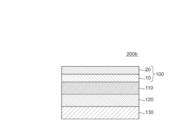
- FIG. 1 is a schematic cross-sectional view of a polarizing plate according to one embodiment of the present invention.
- the polarizing plate 100 of the illustrated example has a polarizing element 10, a first protective layer 20 arranged on one side of the polarizing element 10, and a second protective layer 30 arranged on the other side.
- the polarizing element 10 is made of a polyvinyl alcohol-based resin film containing a dichroic substance.
- the first protective layer 20 is made of a resin film having a thickness of 10 ⁇ m or less.
- the second protective layer 30 may be omitted depending on the purpose.
- a hard coat layer may be provided on the opposite side of the first protective layer 20 from the polarizing element 10, and it is easy between the first protective layer 20 and the polarizing element 10.
- An adhesive layer may be provided.
- the polarizing element 10 satisfies the following formula (1) when the simple substance transmittance is x% and the birefringence of the polyvinyl alcohol-based resin constituting the polarizing element is y. In one embodiment, the polarizing element 10 satisfies the following formula (2) when the simple substance transmittance is x% and the in-plane retardation of the polyvinyl alcohol-based resin film constituting the polarizing element is znm. In one embodiment, the polarizing element 10 satisfies the following formula (3) when the simple substance transmittance is x% and the orientation function of the polyvinyl alcohol-based resin constituting the polarizing element is f. In one embodiment, the puncture strength of the polarizing element is 30 gf / ⁇ m or more. y ⁇ -0.011x + 0.525 (1) z ⁇ -60x + 2875 (2) f ⁇ -0.018x + 1.11 (3)
- the total thickness of the polarizing plate 100 is, for example, 20 ⁇ m or less, preferably 15 ⁇ m or less, further preferably 12 ⁇ m or less, and even more preferably 10 ⁇ m or less.
- the total thickness of the polarizing plate is, for example, 5 ⁇ m or more.
- Each layer or optical film constituting the polarizing plate may be bonded via an adhesive layer, or may be formed in close contact with each other without interposing an adhesive layer.
- the adhesive layer include an adhesive layer and an adhesive layer.
- the adhesive layer can be preferably adopted. With such a configuration, the polarizing plate can be further reduced in thickness.
- Typical examples of the adhesive constituting the adhesive layer include an active energy ray-curable adhesive (for example, an ultraviolet curable adhesive).
- the thickness of the polarizing plate can be extremely thin. Therefore, it can be suitably applied to a flexible image display device. More preferably, the image display device has a curved shape (substantially a curved display screen) and / or is bendable or bendable. Specific examples of the image display device include a liquid crystal display device and an electroluminescence (EL) display device (for example, an organic EL display device and an inorganic EL display device). Needless to say, the above description does not prevent the polarizing plate of the present invention from being applied to a normal image display device.
- EL electroluminescence
- the change amount ⁇ Ts of the simple substance transmittance Ts and the change amount ⁇ P of the degree of polarization P of the polarizing plate after being left in an environment of 60 ° C. and 95% RH for 500 hours are very small, respectively.
- the single transmittance Ts can be measured using, for example, an ultraviolet-visible spectrophotometer (manufactured by JASCO Corporation, product name "V7100").
- the degree of polarization P is calculated by the following equation from the single transmittance (Ts), the parallel transmittance (Tp) and the orthogonal transmittance (Tc) measured by using an ultraviolet-visible spectrophotometer.
- Ts 0 is the single transmittance before leaving (initial)
- Ts 500 is the single transmittance after leaving
- P 0 is the degree of polarization before leaving (initial)
- P 500 is after leaving.
- the degree of polarization. ⁇ Ts is preferably 3.0% or less, more preferably 2.5% or less, still more preferably 2.0% or less, still more preferably 1.5% or less.
- ⁇ P is preferably ⁇ 5.0% to 0%, more preferably ⁇ 3.0% to 0%, still more preferably ⁇ 1.0% to 0%, and even more preferably ⁇ 0. It is 5.5% to 0%.
- the polarizing plate of the present invention may be single-wafer-shaped or long-shaped.
- the term "long” means an elongated shape having a length sufficiently long with respect to the width, and for example, an elongated shape having a length of 10 times or more, preferably 20 times or more with respect to the width. include.
- the long polarizing plate can be wound in a roll shape.
- the polarizing element is composed of a polyvinyl alcohol-based resin film containing a dichroic substance.
- the polarizing element satisfies the following formula (1) when the simple substance transmittance is x% and the birefringence of the polyvinyl alcohol-based resin constituting the polarizing element is y.
- the substituent satisfies the following formula (2) when the simple substance transmittance is x% and the in-plane retardation of the polyvinyl alcohol-based resin film constituting the polarizing element is znm.
- the polarizing element satisfies the following formula (3) when the simple substance transmittance is x% and the orientation function of the polyvinyl alcohol-based resin constituting the polarizing element is f.
- the puncture strength of the polarizing element is 30 gf / ⁇ m or more.
- a polarizing element composed of a polyvinyl alcohol-based resin film containing a bicolor substance, double refraction of PVA-based resin (hereinafter referred to as PVA double refraction or PVA ⁇ n) and in-plane phase difference of PVA-based resin film.
- PVA double refraction or PVA ⁇ n double refraction of PVA-based resin
- in-plane phase difference of PVA the orientation function of PVA-based resin
- orientation function of PVA hereinafter referred to as "orientation function of PVA”
- the piercing strength of the polarizing element all constitute the polarizing element. It is a value related to the degree of orientation of the molecular chain of the PVA-based resin.
- the birefringence, in-plane phase difference and orientation function of PVA can be large as the degree of orientation increases, and the puncture strength can decrease as the degree of orientation increases.
- the polarizing element used in the present invention that is, the polarizing element satisfying the above formulas (1) to (3) or the piercing strength
- the orientation of the molecular chain of the PVA-based resin in the absorption axis direction is gentler than that of the conventional polarizing element. Due to this, heat shrinkage in the absorption axis direction is suppressed. As a result, it is possible to obtain a polarizing plate that is extremely thin and has suppressed crack generation during heating.
- a polarizing element is also excellent in flexibility, it is possible to obtain a polarizing plate having excellent flexibility and bending durability, preferably a curved image display device, and more preferably a bendable image. It can be applied to display devices, more preferably foldable image display devices. Conventionally, it has been difficult to obtain acceptable optical characteristics (typically, simple substance transmittance and degree of polarization) with a polarizing element having a low degree of orientation, but the substituent used in the present invention is lower than the conventional one. It is possible to achieve both the degree of orientation of the PVA-based resin and the acceptable optical characteristics.
- the polarizing element preferably satisfies the following formulas (1a) and / or the formula (2a), and more preferably the following formulas (1b) and / or the formula (2b).
- the in-plane retardation value of PVA is the in-plane retardation value of the PVA-based resin film at 23 ° C. and a wavelength of 1000 nm.
- the birefringence (in-plane birefringence) of PVA is a value obtained by dividing the in-plane birefringence of PVA by the thickness (nm) of the polarizing element.
- the method for evaluating the in-plane phase difference of the PVA is also described in Japanese Patent No. 5923760, and can be referred to as necessary.
- the birefringence ( ⁇ n) of PVA can be calculated by dividing this phase difference by the thickness.
- Examples of commercially available devices for measuring the in-plane phase difference of PVA at a wavelength of 1000 nm include KOBRA-WR / IR series and KOBRA-31X / IR series manufactured by Oji Measurement Co., Ltd.
- the orientation function (f) of the polarizing element used in the present invention preferably satisfies the following formula (3a), and more preferably the following formula (3b). If the orientation function is too small, acceptable single transmittance and / or degree of polarization may not be obtained. -0.01x + 0.50 ⁇ f ⁇ -0.018x + 1.11 (3a) -0.01x + 0.57 ⁇ f ⁇ -0.018x + 1.1 (3b)
- the orientation function (f) is determined by total internal reflection spectroscopy (ATR) measurement using, for example, a Fourier transform infrared spectrophotometer (FT-IR) and polarized light as measurement light.
- ATR total internal reflection spectroscopy
- germanium is used as the crystallite to which the polarizing element is brought into close contact
- the incident angle of the measurement light is 45 °
- the polarized infrared light (measurement light) to be incident is the surface to which the sample of the germanium crystal is brought into close contact.
- the intensity I as a reference peak to 3330cm -1, a value of 2941cm -1 / 3330cm -1.
- the peak of 2941 cm -1 is considered to be absorption caused by the vibration of the main chain (-CH 2-) of PVA in the polarizing element.
- ⁇ Angle of molecular chain with respect to stretching direction
- ⁇ Angle of transition dipole moment with respect to molecular chain axis
- I ⁇ Absorption intensity when the polarization direction of the measurement light and the extension direction of the modulator are perpendicular
- I // Absorption intensity when the polarization direction of the measurement light and the extension direction of the modulator are parallel
- the thickness of the polarizing element is preferably 10 ⁇ m or less, more preferably 8 ⁇ m or less.
- the lower limit of the thickness of the transducer can be, for example, 1 ⁇ m.
- the thickness of the polarizing element may be 2 ⁇ m to 10 ⁇ m in one embodiment and 2 ⁇ m to 8 ⁇ m in another embodiment.
- the polarizing element preferably exhibits absorption dichroism at any wavelength of 380 nm to 780 nm.
- the simple substance transmittance of the polarizing element is preferably 40.0% or more, more preferably 41.0% or more.
- the simple substance transmittance can be, for example, 49.0% or less.
- the simple substance transmittance of the polarizing element is 40.0% to 45.0% in one embodiment.
- the degree of polarization of the polarizing element is preferably 99.0% or more, more preferably 99.4% or more.
- the degree of polarization can be, for example, 99.999% or less.
- the degree of polarization of the polarizing element is 99.0% to 99.99% in one embodiment.
- the polarizing element used in the present invention has a lower degree of orientation of the PVA-based resin constituting the polarizing element than the conventional one and has the above-mentioned in-plane phase difference, birefringence and / or orientation function.
- One of the features is that such a practically acceptable single-unit transmittance and degree of polarization can be realized. It is presumed that this is due to the manufacturing method described later.
- the single transmittance is typically a Y value measured with an ultraviolet-visible spectrophotometer and corrected for luminosity factor.
- the degree of polarization is typically determined by the following equation based on the parallel transmittance Tp and the orthogonal transmittance Tc measured with an ultraviolet-visible spectrophotometer and corrected for luminosity factor.
- Polarization degree (%) ⁇ (Tp-Tc) / (Tp + Tc) ⁇ 1/2 ⁇ 100
- the puncture strength of the polarizing element is, for example, 30 gf / ⁇ m or more, preferably 35 gf / ⁇ m or more, more preferably 40 gf / ⁇ m or more, still more preferably 45 gf / ⁇ m or more, and particularly preferably 50 gf / ⁇ m or more. That is all.
- the upper limit of the piercing strength can be, for example, 80 gf / ⁇ m.
- the piercing strength indicates the cracking resistance of the polarizing element when the polarizing element is pierced with a predetermined strength.
- the piercing strength can be expressed as, for example, the strength (breaking strength) at which the polarizing element is cracked when a predetermined needle is attached to a compression tester and the needle is pierced into the polarizing element at a predetermined speed.
- the piercing strength means the piercing strength per unit thickness (1 ⁇ m) of the polarizing element.
- the polarizing element is composed of a PVA-based resin film containing a dichroic substance.
- the PVA-based resin constituting the PVA-based resin film (substantially, a polarizing element) contains an acetoacetyl-modified PVA-based resin.
- a polarizing element having a desired piercing strength can be obtained.
- the blending amount of the acetoacetyl-modified PVA-based resin is preferably 5% by weight to 20% by weight, more preferably 8% by weight to 12% by weight, when the total amount of the PVA-based resin is 100% by weight. .. When the blending amount is in such a range, the piercing strength can be in a more suitable range.
- the decoder can typically be made using a laminate of two or more layers.
- Specific examples of the polarizing element obtained by using the laminated body include a polarizing element obtained by using a laminated body of a resin base material and a PVA-based resin layer coated and formed on the resin base material.
- the polarizing element obtained by using the laminate of the resin base material and the PVA-based resin layer coated and formed on the resin base material is, for example, a resin base material obtained by applying a PVA-based resin solution to the resin base material and drying it.
- a PVA-based resin layer is formed on the PVA-based resin layer to obtain a laminate of a resin base material and a PVA-based resin layer; and stretching and dyeing the laminate to make the PVA-based resin layer a stator. obtain.
- a polyvinyl alcohol-based resin layer containing a halide and a polyvinyl alcohol-based resin is preferably formed on one side of the resin base material. Stretching typically involves immersing the laminate in an aqueous boric acid solution for stretching. Further, stretching preferably further comprises stretching the laminate in the air at a high temperature (eg, 95 ° C. or higher) prior to stretching in an aqueous boric acid solution.
- the total magnification of stretching is preferably 3.0 to 4.5 times, which is significantly smaller than usual. Even at the total magnification of such stretching, a stator having acceptable optical properties can be obtained by combining the addition of a halide and the drying shrinkage treatment.
- the stretching ratio of the aerial auxiliary stretching is preferably larger than the stretching ratio of the boric acid water stretching. With such a configuration, it is possible to obtain a polarizing element having acceptable optical characteristics even if the total magnification of stretching is small.
- the laminate is preferably subjected to a dry shrinkage treatment of shrinking by 2% or more in the width direction by heating while transporting in the longitudinal direction.
- the method for producing a polarizing element includes subjecting a laminate to an aerial auxiliary stretching treatment, a dyeing treatment, an underwater stretching treatment, and a drying shrinkage treatment in this order.
- auxiliary stretching even when the PVA-based resin is coated on the thermoplastic resin, the crystallinity of the PVA-based resin can be enhanced, and high optical characteristics can be achieved.
- by increasing the orientation of the PVA-based resin in advance it is possible to prevent problems such as deterioration of the orientation of the PVA-based resin and dissolution when immersed in water in the subsequent dyeing step or stretching step. , It becomes possible to achieve high optical characteristics.
- the disorder of the orientation of the polyvinyl alcohol molecule and the decrease in the orientation can be suppressed as compared with the case where the PVA-based resin layer does not contain a halide.
- This makes it possible to improve the optical characteristics of the polarizing element obtained through a treatment step of immersing the laminate in a liquid, such as a dyeing treatment and a stretching treatment in water. Further, the optical characteristics can be improved by shrinking the laminated body in the width direction by the drying shrinkage treatment.
- the obtained resin base material / polarizing element laminate may be used as it is (that is, the resin base material may be used as a protective layer for the polarizing element), and the resin base material is peeled off from the resin base material / polarizing element laminate. Then, an arbitrary appropriate protective layer according to the purpose may be laminated on the peeled surface and used.
- the details of the method for manufacturing the stator will be described in detail in Section A-3.
- A-3. Method for Producing a Polarizer polyvinyl alcohol containing a halide and a polyvinyl alcohol-based resin (PVA-based resin) on one side of a long thermoplastic resin base material is used.
- PVA-based resin layer a based resin layer
- a drying shrinkage treatment of shrinking by 1% to 10% in the width direction and a drying shrinkage treatment are performed in this order.
- the content of the halide in the PVA-based resin layer is preferably 5 parts by weight to 20 parts by weight with respect to 100 parts by weight of the PVA-based resin.
- the drying shrinkage treatment is preferably performed using a heating roll, and the temperature of the heating roll is preferably 60 ° C. to 120 ° C.
- the shrinkage rate in the width direction of the laminated body by the drying shrinkage treatment is preferably 1% to 10%. According to such a manufacturing method, the modulator described in Section A-2 above can be obtained.
- a stator having excellent optical properties (typically, single transmittance and degree of polarization).
- A-3-1 Preparation of Laminate
- any appropriate method can be adopted.
- a coating liquid containing a halide and a PVA-based resin is applied to the surface of the thermoplastic resin base material and dried to form a PVA-based resin layer on the thermoplastic resin base material.
- the content of the halide in the PVA-based resin layer is preferably 5 parts by weight to 20 parts by weight with respect to 100 parts by weight of the PVA-based resin.
- any appropriate method can be adopted as the application method of the coating liquid.
- a roll coating method, a spin coating method, a wire bar coating method, a dip coating method, a die coating method, a curtain coating method, a spray coating method, a knife coating method (comma coating method, etc.) and the like can be mentioned.
- the coating / drying temperature of the coating liquid is preferably 50 ° C. or higher.
- the thickness of the PVA-based resin layer is preferably 2 ⁇ m to 30 ⁇ m, more preferably 2 ⁇ m to 20 ⁇ m.
- the thermoplastic resin base material Before forming the PVA-based resin layer, the thermoplastic resin base material may be surface-treated (for example, corona treatment or the like), or the easy-adhesion layer may be formed on the thermoplastic resin base material. By performing such a treatment, the adhesion between the thermoplastic resin base material and the PVA-based resin layer can be improved.
- thermoplastic resin substrate any suitable thermoplastic resin film can be adopted. Details of the thermoplastic resin base material are described in, for example, Japanese Patent Application Laid-Open No. 2012-73580 and Japanese Patent No. 6470455. The entire description of the publication is incorporated herein by reference.
- the coating liquid contains a halide and a PVA-based resin as described above.
- the coating liquid is typically a solution in which the halide and the PVA-based resin are dissolved in a solvent.
- the solvent include water, dimethyl sulfoxide, dimethylformamide, dimethylacetamide, N-methylpyrrolidone, various glycols, polyhydric alcohols such as trimethylolpropane, and amines such as ethylenediamine and diethylenetriamine. These can be used alone or in combination of two or more. Among these, water is preferable.
- the PVA-based resin concentration of the solution is preferably 3 parts by weight to 20 parts by weight with respect to 100 parts by weight of the solvent.
- the content of the halide in the coating liquid is preferably 5 parts by weight to 20 parts by weight with respect to 100 parts by weight of the PVA-based resin.
- Additives may be added to the coating liquid.
- the additive include a plasticizer, a surfactant and the like.
- the plasticizer include polyhydric alcohols such as ethylene glycol and glycerin.
- the surfactant include nonionic surfactants. These can be used for the purpose of further improving the uniformity, dyeability, and stretchability of the obtained PVA-based resin layer.
- any suitable resin can be adopted as the PVA-based resin.
- polyvinyl alcohol and ethylene-vinyl alcohol copolymers can be mentioned.
- Polyvinyl alcohol is obtained by saponifying polyvinyl acetate.
- the ethylene-vinyl alcohol copolymer is obtained by saponifying the ethylene-vinyl acetate copolymer.
- the saponification degree of the PVA-based resin is usually 85 mol% to 100 mol%, preferably 95.0 mol% to 99.95 mol%, and more preferably 99.0 mol% to 99.93 mol%. ..
- the degree of saponification can be determined according to JIS K 6726-1994.
- the PVA-based resin By using a PVA-based resin having such a degree of saponification, a polarizing element having excellent durability can be obtained. If the degree of saponification is too high, gelation may occur.
- the PVA-based resin preferably contains an acetoacetyl-modified PVA-based resin.
- the average degree of polymerization of the PVA-based resin can be appropriately selected according to the purpose.
- the average degree of polymerization is usually 1000 to 10000, preferably 1200 to 4500, and more preferably 1500 to 4300.
- the average degree of polymerization can be determined according to JIS K 6726-1994.
- any suitable halide can be adopted.
- iodide and sodium chloride can be mentioned.
- Iodides include, for example, potassium iodide, sodium iodide, and lithium iodide. Among these, potassium iodide is preferable.
- the amount of the halide in the coating liquid is preferably 5 parts by weight to 20 parts by weight with respect to 100 parts by weight of the PVA-based resin, and more preferably 10 parts by weight to 15 parts by weight with respect to 100 parts by weight of the PVA-based resin. It is a department. If the amount of the halide exceeds 20 parts by weight with respect to 100 parts by weight of the PVA-based resin, the halide may bleed out and the finally obtained polarizing element may become cloudy.
- the stretching of the PVA-based resin layer increases the orientation of the polyvinyl alcohol molecules in the PVA-based resin layer.
- the stretched PVA-based resin layer is immersed in a liquid containing water, the polyvinyl alcohol molecules become higher. The orientation of the plastic may be disturbed and the orientation may decrease.
- the laminate of the thermoplastic resin base material and the PVA-based resin layer is stretched in boric acid water, the laminate is stretched in boric acid water at a relatively high temperature in order to stabilize the stretching of the thermoplastic resin base material. In the case of stretching, the tendency of the degree of orientation to decrease is remarkable.
- stretching a PVA film alone in boric acid water is generally performed at 60 ° C.
- stretching of a laminate of A-PET (thermoplastic resin base material) and a PVA-based resin layer is performed. It is carried out at a high temperature of about 70 ° C., and in this case, the orientation of PVA at the initial stage of stretching may decrease before it is increased by stretching in water.
- A-PET thermoplastic resin base material
- auxiliary stretching before stretching it in boric acid water.
- Crystallization of the PVA-based resin in the PVA-based resin layer of the laminated body after the auxiliary stretching can be promoted.
- the disorder of the orientation of the polyvinyl alcohol molecule and the decrease in the orientation can be suppressed as compared with the case where the PVA-based resin layer does not contain a halide.
- A-3-2 Aerial auxiliary stretching treatment
- a two-stage stretching method that combines dry stretching (auxiliary stretching) and boric acid water stretching is selected.
- auxiliary stretching as in the case of two-step stretching, it is possible to stretch while suppressing the crystallization of the thermoplastic resin base material.
- the PVA-based resin is applied on the thermoplastic resin base material, it is compared with the case where the PVA-based resin is applied on a normal metal drum in order to suppress the influence of the glass transition temperature of the thermoplastic resin base material. Therefore, it is necessary to lower the coating temperature, and as a result, the crystallization of the PVA-based resin becomes relatively low, which may cause a problem that sufficient optical characteristics cannot be obtained.
- the stretching method of the aerial auxiliary stretching may be fixed-end stretching (for example, a method of stretching using a tenter stretching machine) or free-end stretching (for example, a method of uniaxial stretching through a laminate between rolls having different peripheral speeds). .. Free-end stretching can be positively adopted in order to obtain high optical properties.
- the aerial stretching treatment includes a heating roll stretching step of stretching the laminate by the difference in peripheral speed between the heating rolls while transporting the laminated body in the longitudinal direction thereof.
- the aerial stretching treatment typically includes a zone stretching step and a heating roll stretching step.
- the order of the zone stretching step and the heating roll stretching step is not limited, and the zone stretching step may be performed first, or the heating roll stretching step may be performed first.
- the zone stretching step may be omitted.
- the zone stretching step and the heating roll stretching step are performed in this order.
- the film in the tenter stretching machine, is stretched by grasping the end portion of the film and widening the distance between the tenters in the flow direction (the widening of the distance between the tenters is the stretching ratio).
- the distance of the tenter in the width direction (perpendicular to the flow direction) is set to approach arbitrarily.
- it can be set to be closer to the free end stretch with respect to the stretch ratio in the flow direction.
- the aerial auxiliary stretching may be performed in one step or in multiple steps. When performed in multiple stages, the draw ratio is the product of the draw ratios in each stage.
- the stretching direction in the aerial auxiliary stretching is preferably substantially the same as the stretching direction in the underwater stretching.
- the draw ratio in the aerial auxiliary stretching is preferably 1.0 to 4.0 times, more preferably 1.5 to 3.5 times, and further preferably 2.0 to 3.0 times. be.
- the stretching ratio of the aerial auxiliary stretching is in such a range, the total stretching ratio can be set in a desired range when combined with the underwater stretching, and a desired orientation function can be realized. As a result, it is possible to obtain a polarizing element in which crack generation due to heating is suppressed. Further, as described above, it is preferable that the stretching ratio of the aerial auxiliary stretching is larger than the stretching ratio of the boric acid water stretching. With such a configuration, it is possible to obtain a polarizing element having acceptable optical characteristics even if the total magnification of stretching is small. More specifically, the ratio of the stretching ratio of the aerial auxiliary stretching to the stretching ratio of the underwater stretching (underwater stretching / aerial auxiliary stretching) is preferably 0.4 to 0.9, more preferably 0.5 to 0. It is 8.8.
- the stretching temperature of the aerial auxiliary stretching can be set to an arbitrary appropriate value depending on the forming material of the thermoplastic resin base material, the stretching method, and the like.
- the stretching temperature is preferably the glass transition temperature (Tg) or higher of the thermoplastic resin base material, more preferably the glass transition temperature (Tg) of the thermoplastic resin base material (Tg) + 10 ° C. or higher, and particularly preferably Tg + 15 ° C. or higher.
- the upper limit of the stretching temperature is preferably 170 ° C.
- an insolubilization treatment is performed after the aerial auxiliary stretching treatment and before the underwater stretching treatment or the dyeing treatment.
- the insolubilization treatment is typically performed by immersing a PVA-based resin layer in a boric acid aqueous solution.
- the dyeing treatment is typically performed by dyeing the PVA-based resin layer with a dichroic substance (typically iodine).
- a cross-linking treatment is performed after the dyeing treatment and before the underwater stretching treatment.
- the cross-linking treatment is typically performed by immersing a PVA-based resin layer in an aqueous boric acid solution. Details of the insolubilization treatment, the dyeing treatment and the crosslinking treatment are described in, for example, Japanese Patent Application Laid-Open No. 2012-73580 (above).
- thermoplastic resin base material or the PVA-based resin layer can be stretched at a temperature lower than the glass transition temperature (typically, about 80 ° C.), and the PVA-based resin layer is crystallized. Can be stretched while suppressing. As a result, it is possible to manufacture a polarizing element having excellent optical characteristics.
- any appropriate method can be adopted as the stretching method of the laminated body. Specifically, it may be fixed-end stretching or free-end stretching (for example, a method of uniaxial stretching through a laminate between rolls having different peripheral speeds). Preferably, free-end stretching is selected.
- the stretching of the laminate may be carried out in one step or in multiple steps. When performed in multiple stages, the total stretching ratio is the product of the stretching ratios in each stage.
- the underwater stretching is preferably carried out by immersing the laminate in a boric acid aqueous solution (boric acid water stretching).
- boric acid aqueous solution as the stretching bath, it is possible to impart rigidity to withstand the tension applied during stretching and water resistance that does not dissolve in water to the PVA-based resin layer.
- boric acid can generate a tetrahydroxyboric acid anion in an aqueous solution and crosslink with a PVA-based resin by hydrogen bonding.
- the PVA-based resin layer can be imparted with rigidity and water resistance, can be stretched satisfactorily, and a polarizing element having excellent optical characteristics can be produced.
- the boric acid aqueous solution is preferably obtained by dissolving boric acid and / or borate in water as a solvent.
- the boric acid concentration is preferably 1 part by weight to 10 parts by weight, more preferably 2.5 parts by weight to 6 parts by weight, and particularly preferably 3 parts by weight to 5 parts by weight with respect to 100 parts by weight of water. Is.
- the boric acid concentration is preferably 1 part by weight or more, the dissolution of the PVA-based resin layer can be effectively suppressed, and a polarizing element having higher characteristics can be produced.
- an aqueous solution obtained by dissolving a boron compound such as borax, glyoxal, glutaraldehyde or the like in a solvent can also be used.
- iodide is added to the above stretching bath (boric acid aqueous solution).
- the elution of iodine adsorbed on the PVA-based resin layer can be suppressed.
- Specific examples of iodide are as described above.
- the concentration of iodide is preferably 0.05 parts by weight to 15 parts by weight, and more preferably 0.5 parts by weight to 8 parts by weight with respect to 100 parts by weight of water.
- the stretching temperature (liquid temperature of the stretching bath) is preferably 40 ° C to 85 ° C, more preferably 60 ° C to 75 ° C. At such a temperature, the PVA-based resin layer can be stretched at a high magnification while suppressing dissolution.
- the glass transition temperature (Tg) of the thermoplastic resin base material is preferably 60 ° C. or higher in relation to the formation of the PVA-based resin layer. In this case, if the stretching temperature is lower than 40 ° C., there is a possibility that the thermoplastic resin base material cannot be stretched satisfactorily even if the plasticization of the thermoplastic resin base material by water is taken into consideration.
- the higher the temperature of the stretching bath the higher the solubility of the PVA-based resin layer, and there is a possibility that excellent optical characteristics cannot be obtained.
- the immersion time of the laminate in the stretching bath is preferably 15 seconds to 5 minutes.
- the stretching ratio by stretching in water is preferably 1.0 to 2.2 times, more preferably 1.1 times to 2.0 times, and further preferably 1.1 times to 1.8 times. , Even more preferably 1.2 to 1.6 times.
- the total stretching ratio can be set in a desired range, and the desired birefringence, in-plane retardation and / or orientation function can be realized. As a result, it is possible to obtain a polarizing element in which crack generation due to heating is suppressed.
- the total stretching ratio (the total stretching ratio when the aerial auxiliary stretching and the underwater stretching are combined) is preferably 3.0 to 4.5 times with respect to the original length of the laminated body.
- the dry shrinkage treatment may be performed by heating the entire zone by heating the zone, or by heating the transport roll (using a so-called heating roll) (heating roll drying method). Preferably both are used.
- heating roll heating roll drying method
- the crystallization of the thermoplastic resin base material can be efficiently promoted and the crystallinity can be increased, which is relatively low. Even at the drying temperature, the crystallinity of the thermoplastic resin substrate can be satisfactorily increased.
- the rigidity of the thermoplastic resin base material is increased, and the PVA-based resin layer is in a state of being able to withstand shrinkage due to drying, and curling is suppressed.
- the laminated body can be dried while being maintained in a flat state, so that not only curling but also wrinkles can be suppressed.
- the laminated body can be improved in optical characteristics by shrinking in the width direction by a drying shrinkage treatment. This is because the orientation of PVA and the PVA / iodine complex can be effectively enhanced.
- the shrinkage ratio in the width direction of the laminate by the drying shrinkage treatment is preferably 1% to 10%, more preferably 2% to 8%, and particularly preferably 4% to 6%.
- FIG. 2 is a schematic view showing an example of the drying shrinkage treatment.
- the laminate 50 is dried while being transported by the transport rolls R1 to R6 heated to a predetermined temperature and the guide rolls G1 to G4.
- the transport rolls R1 to R6 are arranged so as to alternately and continuously heat the surface of the PVA resin layer and the surface of the thermoplastic resin base material.
- one surface of the laminate 50 (for example, thermoplasticity) is arranged.
- the transport rolls R1 to R6 may be arranged so as to continuously heat only the resin substrate surface).
- Drying conditions can be controlled by adjusting the heating temperature of the transport roll (temperature of the heating roll), the number of heating rolls, the contact time with the heating roll, and the like.
- the temperature of the heating roll is preferably 60 ° C. to 120 ° C., more preferably 65 ° C. to 100 ° C., and particularly preferably 70 ° C. to 80 ° C.
- the crystallinity of the thermoplastic resin can be satisfactorily increased, curling can be satisfactorily suppressed, and an optical laminate having extremely excellent durability can be produced.
- the temperature of the heating roll can be measured with a contact thermometer. In the illustrated example, six transport rolls are provided, but there is no particular limitation as long as there are a plurality of transport rolls.
- the number of transport rolls is usually 2 to 40, preferably 4 to 30.
- the contact time (total contact time) between the laminate and the heating roll is preferably 1 second to 300 seconds, more preferably 1 to 20 seconds, and further preferably 1 to 10 seconds.
- the heating roll may be provided in a heating furnace (for example, an oven) or in a normal production line (in a room temperature environment). Preferably, it is provided in a heating furnace provided with a blowing means.
- a heating furnace provided with a blowing means.
- the temperature of hot air drying is preferably 30 ° C to 100 ° C.
- the hot air drying time is preferably 1 second to 300 seconds.
- the wind speed of the hot air is preferably about 10 m / s to 30 m / s. The wind speed is the wind speed in the heating furnace and can be measured by a mini-vane type digital anemometer.
- a washing treatment is performed after the underwater stretching treatment and before the drying shrinkage treatment.
- the cleaning treatment is typically performed by immersing a PVA-based resin layer in an aqueous potassium iodide solution.
- the thickness of the first protective layer is 10 ⁇ m or less.
- the thickness of the first protective layer is 10 ⁇ m or less, it can contribute to the thinning of the polarizing plate.
- a protective layer having a thickness of 20 ⁇ m or more has been used.
- the polarizing element used in the embodiment of the present invention has a lower degree of orientation of the PVA-based resin than the conventional one, and as a result, shrinkage due to heating is small, so that the protective layer has a thickness of 10 ⁇ m or less. Even when the above is used, the generation of cracks during heating is suppressed.
- the thickness of the first protective layer is preferably 7 ⁇ m or less, more preferably 5 ⁇ m or less, and further preferably 3 ⁇ m or less.
- the thickness of the first protective layer is, for example, 1 ⁇ m or more.
- the first protective layer is composed of a resin film.
- any suitable resin can be used depending on the purpose. Specific examples include (meth) acrylic, cellulose-based such as triacetylcellulose (TAC), polyester-based, polyurethane-based, polyvinyl alcohol-based, polycarbonate-based, polyamide-based, polyimide-based, polyethersulfone-based, polysulfone-based, and polystyrene.
- Thermoplastic resins such as (meth) acrylic, urethane, (meth) acrylic urethane, epoxy, silicone, etc., or active energy ray-curable resins.
- Resin Glassy polymers such as siloxane-based polymers can be mentioned.
- as the resin forming the resin film at least one resin selected from an epoxy resin, a (meth) acrylic resin, a polyester resin, and a urethane resin is used.
- the resin film constituting the first protective layer may be, for example, a molded product of a molten resin, and is a solidified coating film of a resin solution obtained by dissolving or dispersing the resin in an aqueous solvent or an organic solvent. It may be a cured product of a curable resin (for example, a photocationic cured product).
- the first protective layer is a coating film of an organic solvent solution of a thermoplastic (meth) acrylic resin (hereinafter, the (meth) acrylic resin may be simply referred to as “acrylic resin”). It is composed of at least one selected from the group consisting of a solidified product of the above, a photocationically cured product of an epoxy resin, and a solidified product of a coating film of an organic solvent solution of an epoxy resin.
- acrylic resin thermoplastic (meth) acrylic resin
- the first protective layer is composed of the solidification of the coating film of the organic solvent solution of the thermoplastic acrylic resin.
- the softening temperature of the first protective layer of the present embodiment is preferably 100 ° C. or higher, more preferably 115 ° C. or higher, still more preferably 120 ° C. or higher, and particularly preferably 125 ° C. or higher. Further, from the viewpoint of moldability, it is preferably 300 ° C. or lower, more preferably 250 ° C. or lower, still more preferably 200 ° C. or lower, and particularly preferably 160 ° C. or lower.
- the acrylic resin has a glass transition temperature (Tg) of preferably 100 ° C. or higher.
- Tg glass transition temperature
- the softening temperature of the first protective layer is also about 100 ° C. or higher.
- the Tg of the acrylic resin is more preferably 110 ° C. or higher, further preferably 115 ° C. or higher, still more preferably 120 ° C. or higher, and particularly preferably 125 ° C. or higher.
- the Tg of the acrylic resin is preferably 300 ° C. or lower, more preferably 250 ° C. or lower, still more preferably 200 ° C. or lower, and particularly preferably 160 ° C. or lower. When the Tg of the acrylic resin is in such a range, the moldability can be excellent.
- the acrylic resin any suitable acrylic resin can be adopted as long as it has Tg as described above.
- the acrylic resin typically contains an alkyl (meth) acrylate as a main component as a monomer unit (repeating unit).
- (meth) acrylic means acrylic and / or methacryl.
- alkyl (meth) acrylate constituting the main skeleton of the acrylic resin include linear or branched alkyl groups having 1 to 18 carbon atoms. These can be used alone or in combination.
- any suitable copolymerization monomer may be introduced into the acrylic resin by copolymerization.
- the repeating unit derived from alkyl (meth) acrylate is typically represented by the following general formula (1):
- R 4 represents a hydrogen atom or a methyl group
- R 5 is a hydrogen atom or an aliphatic or alicyclic hydrocarbon group having 1 to 6 carbon atoms which may be substituted. show.
- the substituent include halogens and hydroxyl groups.
- alkyl (meth) acrylate include methyl (meth) acrylate, ethyl (meth) acrylate, n-propyl (meth) acrylate, n-butyl (meth) acrylate, and t-butyl (meth) acrylate.
- R 5 is preferably a
- Acrylic resins may also include only a single alkyl (meth) acrylate units, even if R 4 and R 5 include a plurality of different alkyl (meth) acrylate unit in the above general formula (1) good.
- the content ratio of the alkyl (meth) acrylate unit in the acrylic resin is preferably 50 mol% to 98 mol%, more preferably 55 mol% to 98 mol%, still more preferably 60 mol% to 98 mol%, and particularly preferably. It is 65 mol% to 98 mol%, most preferably 70 mol% to 97 mol%. If the content ratio is less than 50 mol%, the effects expressed from the alkyl (meth) acrylate unit (for example, high heat resistance and high transparency) may not be sufficiently exhibited. If the content ratio is more than 98 mol%, the resin is brittle and easily cracked, high mechanical strength cannot be sufficiently exhibited, and productivity may be inferior.
- the acrylic resin preferably has a repeating unit containing a ring structure.
- the repeating unit including a ring structure include a lactone ring unit, a glutaric anhydride unit, a glutarimide unit, a maleic anhydride unit, and a maleimide (N-substituted maleimide) unit. Only one type of the repeating unit including the ring structure may be contained in the repeating unit of the acrylic resin, or two or more types may be contained.
- the lactone ring unit is preferably represented by the following general formula (2):
- R 1 , R 2 and R 3 independently represent a hydrogen atom or an organic residue having 1 to 20 carbon atoms.
- the organic residue may contain an oxygen atom.
- the acrylic resin may contain only a single lactone ring unit, or may contain a plurality of lactone ring units having different R 1 , R 2 and R 3 in the above general formula (2). ..
- An acrylic resin having a lactone ring unit is described in, for example, Japanese Patent Application Laid-Open No. 2008-181078, and the description in this publication is incorporated herein by reference.
- the glutarimide unit is preferably represented by the following general formula (3):
- R 11 and R 12 each independently represent hydrogen or an alkyl group having 1 to 8 carbon atoms
- R 13 is hydrogen, an alkyl group having 1 to 18 carbon atoms, and 3 carbon atoms. It shows a cycloalkyl group of about 12 or an aryl group having 6 to 10 carbon atoms.
- R 11 and R 12 are independently hydrogen or methyl groups
- R 13 is a hydrogen, methyl group, butyl group or cyclohexyl group, respectively. More preferably, R 11 is a methyl group, R 12 is a hydrogen, and R 13 is a methyl group.
- the acrylic resin may contain only a single glutarimide unit, or may contain a plurality of glutarimide units having different R 11 , R 12 and R 13 in the above general formula (3). ..
- Examples of the acrylic resin having a glutarimide unit include JP-A-2006-309033, JP-A-2006-317560, JP-A-2006-328334, JP-A-2006-337491, and JP-A-2006-337492. It is described in Japanese Patent Application Laid-Open No. 2006-337493 and Japanese Patent Application Laid-Open No. 2006-337569, and the description of this publication is incorporated herein by reference. Note that the glutaric anhydride units, nitrogen atom substituted by R 13 in the general formula (3), except that the oxygen atom, the above description is applied about the glutarimide units.
- the structure of the maleic anhydride unit and the maleimide (N-substituted maleimide) unit is specified from the name, so specific description thereof will be omitted.
- the content ratio of the repeating unit including the ring structure in the acrylic resin is preferably 1 mol% to 50 mol%, more preferably 10 mol% to 40 mol%, and further preferably 20 mol% to 30 mol%. If the content ratio is too small, Tg may be less than 100 ° C., and the heat resistance, solvent resistance and surface hardness of the obtained protective layer may be insufficient. If the content is too high, moldability and transparency may be insufficient.
- the acrylic resin may contain a repeating unit other than an alkyl (meth) acrylate unit and a repeating unit including a ring structure.
- a repeating unit include a repeating unit derived from a vinyl-based monomer copolymerizable with the monomer constituting the above unit (another vinyl-based monomer unit).
- other vinyl-based monomers include acrylic acid, methacrylic acid, crotonic acid, 2- (hydroxymethyl) acrylic acid, 2- (hydroxyethyl) acrylic acid, acrylonitrile, methacrylonitrile, etacrylonitrile, and allyl.
- Glycidyl ether maleic anhydride, itaconic anhydride, N-methylmaleimide, N-ethylmaleimide, N-cyclohexylmaleimide, aminoethyl acrylate, propylaminoethyl acrylate, dimethylaminoethyl methacrylate, ethylaminopropyl methacrylate, methacryl Cyclohexylaminoethyl acid, N-vinyldiethylamine, N-acetylvinylamine, allylamine, methallylamine, N-methylallylamine, 2-isopropenyl-oxazoline, 2-vinyl-oxazoline, 2-acroyl-oxazoline, N-phenylmaleimide, Examples thereof include phenylaminoethyl methacrylate, styrene, ⁇ -methylstyrene, p-glycidylstyrene, p-a
- the weight average molecular weight of the acrylic resin is preferably 1,000,000 to 2000000, more preferably 5000 to 1,000,000, still more preferably 10,000 to 500,000, particularly preferably 50,000 to 500,000, and most preferably 60,000 to 150,000.
- the weight average molecular weight can be determined by polystyrene conversion using, for example, a gel permeation chromatograph (GPC system, manufactured by Tosoh). Tetrahydrofuran can be used as the solvent.
- the acrylic resin can be polymerized by any suitable polymerization method by appropriately combining the above-mentioned monomer units.
- an acrylic resin and another resin may be used in combination. That is, the monomer component constituting the acrylic resin and the monomer component constituting the other resin may be copolymerized, and the copolymer may be used for molding the protective layer described later; the acrylic resin and the other resin.
- the blend of may be used for forming the protective layer.
- other resins include thermoplastic resins such as styrene resin, polyethylene, polypropylene, polyamide, polyphenylene sulfide, polyether ether ketone, polyester, polysulfone, polyphenylene oxide, polyacetal, polyimide, and polyetherimide.
- the type and blending amount of the resin to be used in combination can be appropriately set according to the purpose and the desired characteristics of the obtained film.
- a styrene resin preferably an acrylonitrile-styrene copolymer
- a retardation control agent preferably an acrylonitrile-styrene copolymer
- the content of the acrylic resin in the first protective layer of the present embodiment is preferably 50% by weight to 100% by weight, more preferably 60% by weight to 100% by weight, still more preferably 70% by weight to 100% by weight. Particularly preferably, it is 80% by weight to 100% by weight. If the content is less than 50% by weight, the high heat resistance and high transparency inherent in the acrylic resin may not be sufficiently reflected.
- the first protective layer of the present embodiment can be formed, for example, by applying an organic solvent solution of an acrylic resin to the surface of a polarizing element to form a coating film, and solidifying the coating film.
- any suitable organic solvent capable of dissolving or uniformly dispersing the acrylic resin can be used.
- the organic solvent include ethyl acetate, toluene, methyl ethyl ketone (MEK), methyl isobutyl ketone (MIBK), cyclopentanone, and cyclohexanone.
- the concentration of the acrylic resin in the solution is preferably 3 parts by weight to 20 parts by weight with respect to 100 parts by weight of the solvent. With such a resin concentration, a uniform coating film in close contact with the polarizing element can be formed.
- the solution may be applied to any suitable substrate or to a polarizing element.
- the solidified material of the coating film formed on the substrate is transferred to the substituent.
- the coating film is applied to the polarizing element, the coating film is dried (solidified) so that the first protective layer is directly formed on the polarizing element.
- the solution is applied to the polarizing element and a first protective layer is formed directly on the polarizing element.
- the adhesive layer or the pressure-sensitive adhesive layer required for transfer can be omitted, so that the polarizing plate can be further thinned.
- Any suitable method can be adopted as the method for applying the solution. Specific examples include a roll coating method, a spin coating method, a wire bar coating method, a dip coating method, a die coating method, a curtain coating method, a spray coating method, and a knife coating method (comma coating method, etc.).
- a first protective layer can be formed by drying (solidifying) the coating film of the solution.
- the drying temperature is preferably 100 ° C. or lower, more preferably 50 ° C. to 70 ° C. When the drying temperature is in such a range, it is possible to prevent an adverse effect on the polarizing element.
- the drying time can vary depending on the drying temperature. The drying time can be, for example, 1 to 10 minutes.
- the first protective layer is composed of a photocationically cured product of epoxy resin.
- the protective layer forming composition contains a photocationic polymerization initiator.
- the photocationic polymerization initiator is a photosensitizer having a function of a photoacid generator, and a typical example thereof is an ionic onium salt composed of a cation portion and an anion portion. In this onium salt, the cation part absorbs light and the anion part becomes a source of acid.
- Ring-opening polymerization of the epoxy group proceeds by the acid generated from this photocationic polymerization initiator.
- the first protective layer which is the obtained photocationic cured product, has a high softening temperature, and the amount of iodine adsorbed can be reduced. Therefore, it is possible to provide a polarizing plate in which the occurrence of cracks is suppressed and has excellent humidification durability.
- the softening temperature of the first protective layer of the present embodiment is preferably 100 ° C. or higher, more preferably 110 ° C. or higher, still more preferably 120 ° C. or higher, and particularly preferably 125 ° C. or higher. Further, from the viewpoint of moldability, it is preferably 300 ° C. or lower, more preferably 250 ° C. or lower, still more preferably 200 ° C. or lower, and particularly preferably 160 ° C. or lower.
- Epoxy resin As the epoxy resin, any suitable epoxy resin can be used, and an epoxy resin having an aromatic ring or an alicyclic ring can be preferably used. In the present embodiment, an epoxy resin having at least one selected from the group consisting of an aromatic skeleton and a hydrogenated aromatic skeleton can be preferably used. Examples of the aromatic skeleton include a benzene ring, a naphthalene ring, a fluorene ring and the like. Only one type of epoxy resin may be used, or two or more types may be used in combination. Preferably, an epoxy resin having a biphenyl skeleton or a bisphenol skeleton or a hydrogenated product thereof is used as the aromatic skeleton. By using such an epoxy resin, a polarizing plate having more excellent durability and excellent flexibility can be provided.
- an epoxy resin having a biphenyl skeleton will be described in detail.
- the epoxy resin having a biphenyl skeleton is an epoxy resin containing the following structure. Only one type of epoxy resin having a biphenyl skeleton may be used, or two or more types may be used in combination.
- R 14 to R 21 each independently represent a hydrogen atom, a linear or branched substituted or unsubstituted hydrocarbon group having 1 to 12 carbon atoms, or a halogen element).
- R 14 to R 21 independently represent a hydrogen atom, a linear or branched substituted or unsubstituted hydrocarbon group having 1 to 12 carbon atoms, or a halogen element.
- Examples of the linear or branched substituted or unsubstituted hydrocarbon group having 1 to 12 carbon atoms include a methyl group, an ethyl group, an n-propyl group, an isopropyl group, an n-butyl group and a sec-butyl group.
- n-pentyl group isopentyl group, neopentyl group, tert-pentyl group, cyclopentyl group, n-hexyl group, isohexyl group, cyclohexyl group, n-heptyl group, cycloheptyl group, methylcyclohexyl group, n- Octyl group, cyclooctyl group, n-nonyl group, 3,3,5-trimethylcyclohexyl group, n-decyl group, cyclodecyl group, n-undecyl group, n-dodecyl group, cyclododecyl group, phenyl group, benzyl group, Examples thereof include a methylbenzyl group, a dimethylbenzyl group, a trimethylbenzyl group, a naphthylmethyl group, a pheneth
- the linear or branched substituted or unsubstituted hydrocarbon group having 1 to 12 carbon atoms preferably has 1 to 1 to 12 carbon atoms such as a methyl group, an ethyl group, an n-propyl group, an isopropyl group and an n-butyl group.
- the alkyl group of 4 is mentioned.
- Preferred halogen elements include fluorine and bromine.
- the epoxy resin having a biphenyl skeleton is an epoxy resin represented by the following formula. (In the equation, R 14 to R 21 are as described above, and n represents an integer of 0 to 6).
- the epoxy resin having a biphenyl skeleton is an epoxy resin having only a biphenyl skeleton.
- the epoxy resin having a biphenyl skeleton may contain a chemical structure other than the biphenyl skeleton.
- the chemical structure other than the biphenyl skeleton include a bisphenol skeleton, an alicyclic structure, an aromatic ring structure and the like.
- the proportion (molar ratio) of the chemical structure other than the biphenyl skeleton is preferably smaller than that of the biphenyl skeleton.
- a commercially available product may be used as the epoxy resin having a biphenyl skeleton.
- Examples of commercially available products include Mitsubishi Chemical Corporation, trade names: jER YX4000, jER YX4000H, jER YL6121, jER YL664, jER YL6677, jER YL6810, jER YL7399 and the like.
- the epoxy resin (epoxy resin after photocation curing) preferably has a glass transition temperature (Tg) of 100 ° C. or higher.
- Tg glass transition temperature
- the softening temperature of the protective layer is also approximately 100 ° C. or higher.
- the Tg of the epoxy resin is more preferably 110 ° C. or higher, further preferably 120 ° C. or higher, and particularly preferably 125 ° C. or higher.
- the Tg of the epoxy resin is preferably 300 ° C. or lower, more preferably 250 ° C. or lower, still more preferably 200 ° C. or lower, and particularly preferably 160 ° C. or lower. When the Tg of the epoxy resin is in such a range, the moldability can be excellent.
- the epoxy equivalent of the epoxy resin is preferably 100 g / equivalent or more, more preferably 150 g / equivalent or more, and further preferably 200 g / equivalent or more.
- the epoxy equivalent of the epoxy resin is preferably 3000 g / equivalent or less, more preferably 2500 g / equivalent or less, still more preferably 2000 g / equivalent or less.
- a more stable protective layer a protective layer having less residual monomer and sufficiently cured
- "epoxy equivalent” means "mass of epoxy resin containing 1 equivalent of epoxy group” and can be measured according to JIS K7236.
- the above epoxy resin may be used in combination with another resin. That is, even if a blend of the above epoxy resin (for example, an epoxy resin having at least one selected from the group consisting of an aromatic skeleton and a hydrogenated aromatic skeleton) and another resin is used for molding the protective layer. good.
- other resins include thermoplastic resins such as styrene resins, polyethylenes, polypropylenes, polyamides, polyphenylene sulfides, polyether ether ketones, polyesters, polysulfones, polyphenylene oxides, polyacetals, polyimides, and polyetherimides, acrylic resins and Examples thereof include curable resins such as oxetane resins.
- an acrylic resin and an oxetane resin are used.
- the type and blending amount of the resin to be used in combination can be appropriately set according to the purpose and the desired characteristics of the obtained film.
- the styrene resin can be used in combination as a retardation control agent.
- any suitable (meth) acrylic compound can be used.
- the (meth) acrylic compound for example, a (meth) acrylic compound having one (meth) acryloyl group in the molecule (hereinafter, also referred to as “monofunctional (meth) acrylic compound”), intramolecular.
- examples thereof include (meth) acrylic compounds having two or more (meth) acryloyl groups (hereinafter, also referred to as “polyfunctional (meth) acrylic compounds”).
- These (meth) acrylic compounds may be used alone or in combination of two or more.
- These acrylic resins are described in, for example, Japanese Patent Application Laid-Open No. 2019-168500. The entire description of the publication is incorporated herein by reference.
- any suitable compound having one or more oxetanyl groups in the molecule is used.
- Oxetane compound having one oxetane group in the molecule such as oxetane, 3-ethyl-3- (oxylanylmethoxy) oxetane, (meth) acrylic acid (3-ethyloxetane-3-yl) methyl; 3-ethyl- 3 ⁇ [(3-ethyloxetane-3-yl) methoxy] methyl ⁇ oxetane, 1,4-bis [(3-ethyl-3-oxetanyl) methoxymethyl] benzene, 4,4'-bis [(3-ethyl) -3-Oxetane) methoxymethyl]
- An oxetane compound having two or more oxetane groups in a molecule such as biphenyl; and the like. Only one kind of these oxetane resins may be used, or two or more kinds thereof may be combined.
- the oxetane resin is preferably 3-ethyl-3-hydroxymethyloxetane, 1,4-bis [(3-ethyl-3-oxetanyl) methoxymethyl] benzene, 3-ethyl-3- (2-ethylhexyloxymethyl).
- Oxetane, 3-Ethyl-3- (oxylanylmethoxy) oxetane, (meth) acrylic acid (3-ethyloxetane-3-yl) methyl, 3-ethyl-3 ⁇ [(3-ethyloxetane-3-yl) Methyl] methyl ⁇ oxetane and the like are used.
- These oxetane resins are easily available and can be excellent in dilutability (low viscosity) and compatibility.
- an oxetane resin having a molecular weight of 500 or less and liquid at room temperature (25 ° C.) is preferably used from the viewpoint of compatibility and adhesiveness. In one embodiment, it preferably contains an oxetane compound containing two or more oxetanel groups in the molecule, one oxetaneyl group and one (meth) acryloyl group or one epoxy group in the molecule.
- Oxetane compounds are used, more preferably 3-ethyl-3 ⁇ [(3-ethyloxetane-3-yl) methoxy] methyl ⁇ oxetane, 3-ethyl-3- (oxylanylmethoxy) oxetane, (meth) acrylic. Acid (3-ethyloxetane-3-yl) methyl is used.
- oxetane resin a commercially available product may be used. Specifically, Aron Oxetane OXT-101, Aron Oxetane OXT-121, Aron Oxetane OXT-212, and Aron Oxetane OXT-221 (all manufactured by Toagosei Co., Ltd.) can be used. Preferably, Aron Oxetane OXT-101 and Aron Oxetane OXT-221 can be used.
- the content of the epoxy resin (for example, an epoxy resin having at least one selected from the group consisting of an aromatic skeleton and a hydrogenated aromatic skeleton) in the first protective layer of the present embodiment is preferably 50.
- weight% to 100% by weight more preferably 60% by weight to 100% by weight, still more preferably 70% by weight to 100% by weight, and particularly preferably 80% by weight to 100% by weight. If the content is less than 50% by weight, the heat resistance of the protective layer and sufficient adhesion to the polarizing element may not be obtained.
- the content of the oxetane resin is preferably 1 part by weight to 50 parts by weight with respect to 100 parts by weight of the total amount of the epoxy resin and the oxetane resin. It is more preferably 5 parts by weight to 45 parts by weight, and further preferably 10 parts by weight to 40 parts by weight. Within the above range, the curability can be improved and the adhesion between the protective layer and the polarizing element can be improved.
- the photocationic polymerization initiator is a photosensitive agent having a function of a photoacid generator, and a typical example thereof is an ionic onium salt composed of a cation portion and an anion portion. In this onium salt, the cation part absorbs light and the anion part becomes a source of acid. Ring-opening polymerization of the epoxy group proceeds by the acid generated from this photocationic polymerization initiator.
- any suitable compound capable of curing an epoxy resin having at least one selected from the group consisting of an aromatic skeleton and a hydrogenated aromatic skeleton by irradiation with light such as ultraviolet rays. Can be used. Only one type of photocationic polymerization initiator may be used, or two or more types may be used in combination.
- photocationic polymerization initiator examples include triphenylsulfonium hexafluoroantimonate, triphenylsulfonium hexafluorophosphate, p- (phenylthio) phenyldiphenylsulfonium hexafluoroantimonate, p- (phenylthio) phenyldiphenylsulfonium hexafluorophosphate, and the like.
- a triphenylsulfonium salt-based hexafluoroantimonate type photocationic polymerization initiator and a diphenyliodonium salt-based hexafluoroantimonate type photocationic polymerization initiator are used.
- a commercially available product may be used as the photocationic polymerization initiator.
- Commercially available products include triphenylsulfonium salt-based hexafluoroantimonate type SP-170 (manufactured by ADEKA), CPI-101A (manufactured by San-Apro), WPAG-1056 (manufactured by Wako Pure Chemical Industries, Ltd.), and diphenyliodonium salt-based.
- Hexafluoroantimonate type WPI-116 manufactured by Wako Pure Chemical Industries, Ltd.
- WPI-116 manufactured by Wako Pure Chemical Industries, Ltd.
- the content of the photocationic polymerization initiator is preferably 100 parts by weight of the above epoxy resin (for example, an epoxy resin having at least one selected from the group consisting of an aromatic skeleton and a hydrogenated aromatic skeleton). Is 0.1 parts by weight to 3 parts by weight, more preferably 0.25 parts by weight to 2 parts by weight. When the content of the photocationic polymerization initiator is less than 0.1 parts by weight, it may not be sufficiently cured even when irradiated with light (ultraviolet rays).
- a composition containing the epoxy resin and a photocationic polymerization initiator is applied to form a coating film, and the coating film is irradiated with light (for example, ultraviolet rays).
- light for example, ultraviolet rays
- any suitable solvent capable of dissolving or uniformly dispersing the epoxy resin and the curing agent can be used.
- the solvent include ethyl acetate, toluene, methyl ethyl ketone (MEK), methyl isobutyl ketone (MIBK), cyclopentanone, and cyclohexanone.
- the epoxy resin concentration in the above composition is preferably 10 parts by weight to 30 parts by weight with respect to 100 parts by weight of the solvent. With such a resin concentration, a uniform coating film in close contact with the polarizing element can be formed.
- the above composition may be applied to any suitable substrate or may be applied to a polarizing element.
- the cured product of the coating film formed on the substrate is transferred to the substituent.
- the coating film is applied to the polarizing element, the coating film is cured by, for example, light irradiation, so that the first protective layer is directly formed on the polarizing element.
- the composition is applied to a polarizing element and a first protective layer is formed directly on the polarizing element.
- the adhesive layer or the pressure-sensitive adhesive layer required for transfer can be omitted, so that the polarizing plate can be further thinned.
- the method for applying the composition is as described above.
- the coating film When the coating film is cured by light irradiation, the coating film can be irradiated with light (typically ultraviolet rays) so as to have an arbitrary appropriate irradiation amount by using an arbitrary appropriate light source.
- a light source of the ultraviolet rays for example, a low pressure mercury lamp, a high pressure mercury lamp, an ultrahigh pressure mercury lamp, an electrodeless lamp, a carbon arc lamp, a xenon lamp, a metal halide lamp, a chemical lamp, a black light, an LED lamp and the like can be used.
- the dose of ultraviolet rays for example, 2mJ / cm 2 ⁇ 3000mJ / cm 2, preferably 10mJ / cm 2 ⁇ 2000mJ / cm 2.
- the irradiation dose when using a high pressure mercury lamp as a light source, is usually 5mJ / cm 2 ⁇ 3000mJ / cm 2, preferably at the conditions of 50mJ / cm 2 ⁇ 2000mJ / cm 2.
- the irradiation amount is usually 2 mJ / cm 2 to 2000 mJ / cm 2, preferably 10 mJ / cm 2 to 1000 mJ / cm 2 .
- the irradiation time can be set to any appropriate value according to the type of light source, the distance between the light source and the coating surface, the coating thickness, and other conditions.
- the irradiation time is usually several seconds to several tens of seconds, and may be a fraction of a second. Irradiation of light can be performed from any suitable direction. From the viewpoint of preventing non-uniform curing, it is preferable to irradiate from the coated surface side of the protective layer forming composition.
- the heat treatment can be performed at any suitable temperature and time.
- the heating temperature is, for example, 80 ° C. to 250 ° C., preferably 100 ° C. to 150 ° C.
- the heating time is, for example, 10 seconds to 2 hours, preferably 5 minutes to 1 hour.
- the first protective layer is composed of the solidification of the coating film of the organic solvent solution of the epoxy resin.
- the softening temperature of the first protective layer of the present embodiment is preferably 100 ° C. or higher, more preferably 110 ° C. or higher, still more preferably 120 ° C. or higher, and particularly preferably 125 ° C. or higher. Further, from the viewpoint of moldability, it is preferably 300 ° C. or lower, more preferably 250 ° C. or lower, still more preferably 200 ° C. or lower, and particularly preferably 160 ° C. or lower.
- the epoxy resin preferably has a glass transition temperature (Tg) of 100 ° C. or higher.
- Tg glass transition temperature
- the softening temperature of the protective layer is also approximately 100 ° C. or higher.
- the Tg of the epoxy resin is more preferably 110 ° C. or higher, further preferably 120 ° C. or higher, and particularly preferably 125 ° C. or higher.
- the Tg of the epoxy resin is preferably 300 ° C. or lower, more preferably 250 ° C. or lower, still more preferably 200 ° C. or lower, and particularly preferably 160 ° C. or lower.
- the Tg of the epoxy resin is in such a range, the moldability can be excellent.
- the epoxy resin any suitable epoxy resin can be adopted as long as it has Tg as described above.
- the epoxy resin typically refers to a resin having an epoxy group in its molecular structure.
- an epoxy resin having an aromatic ring in the molecular structure is preferably used.
- an epoxy resin having a higher Tg can be obtained.
- the aromatic ring in the epoxy resin having an aromatic ring in the molecular structure include a benzene ring, a naphthalene ring, a fluorene ring and the like. Only one type of epoxy resin may be used, or two or more types may be used in combination. When two or more kinds of epoxy resins are used, an epoxy resin containing an aromatic ring and an epoxy resin not containing an aromatic ring may be used in combination.
- epoxy resin having an aromatic ring in its molecular structure examples include bisphenol A diglycidyl ether type epoxy resin, bisphenol F diglycidyl ether type epoxy resin, bisphenol S diglycidyl ether type epoxy resin, and resorcin diglycidyl ether.
- Type epoxy resin hydroquinone diglycidyl ether type epoxy resin, terephthalic acid diglycidyl ester type epoxy resin, bisphenoxyethanol full orange glycidyl ether type epoxy resin, bisphenol full orange glycidyl ether type epoxy resin, biscresol full orange glycidyl ether type epoxy resin, etc.
- Epoxy resin having two epoxy groups novolak type epoxy resin, N, N, O-triglycidyl-P- or -m-aminophenol type epoxy resin, N, N, O-triglycidyl-4-amino-m -Or-5-Amino-o-cresol type epoxy resin, 1,1,1- (triglycidyloxyphenyl) methane type epoxy resin and other epoxy resins with three epoxy groups; glycidylamine type epoxy resin (eg, diamino) Examples thereof include epoxy resins having four epoxy groups such as diphenylmethane type, diaminodiphenylsulfone type, and metaxylene diamine type).
- a glycidyl ester type epoxy resin such as a hexahydrophthalic anhydride type epoxy resin, a tetrahydrophthalic anhydride type epoxy resin, a dimer acid type epoxy resin, and a p-oxybenzoic acid type may be used.
- the weight average molecular weight of the epoxy resin is preferably 1,000,000 to 2000000, more preferably 5000 to 1,000,000, still more preferably 10,000 to 500,000, particularly preferably 50,000 to 500,000, and most preferably 60,000 to 150,000.
- the weight average molecular weight can be determined by polystyrene conversion using, for example, a gel permeation chromatograph (GPC system, manufactured by Tosoh). Tetrahydrofuran can be used as the solvent.
- the epoxy equivalent of the epoxy resin is preferably 1000 g / equivalent or more, more preferably 3000 g / equivalent or more, and further preferably 5000 g / equivalent or more.
- the epoxy equivalent of the epoxy resin is preferably 30,000 g / equivalent or less, more preferably 25,000 g / equivalent or less, and further preferably 20,000 g / equivalent or less. When the epoxy equivalent is in the above range, a more stable protective layer can be obtained.
- epoxy equivalent means "mass of epoxy resin containing 1 equivalent of epoxy group” and can be measured according to JIS K7236.
- the epoxy resin and another resin may be used in combination. That is, a blend of the epoxy resin and another resin may be used for molding the protective layer.
- other resins include thermoplastic resins such as styrene resin, polyethylene, polypropylene, polyamide, polyphenylene sulfide, polyether ether ketone, polyester, polysulfone, polyphenylene oxide, polyacetal, polyimide, and polyetherimide.
- the type and blending amount of the resin to be used in combination can be appropriately set according to the purpose and the desired characteristics of the obtained film.
- the styrene resin can be used in combination as a retardation control agent.
- the content of the epoxy resin in the first protective layer of the present embodiment is preferably 50% by weight to 100% by weight, more preferably 60% by weight to 100% by weight, still more preferably 70% by weight to 100% by weight. Particularly preferably, it is 80% by weight to 100% by weight. If the content is less than 50% by weight, the heat resistance of the protective layer and sufficient adhesion to the polarizing element may not be obtained.
- the first protective layer of the present embodiment can be formed, for example, by applying an organic solvent solution containing the epoxy resin to form a coating film and solidifying the coating film.
- the epoxy resin concentration in the organic solvent solution is preferably 3 parts by weight to 20 parts by weight with respect to 100 parts by weight of the solvent. With such a resin concentration, a uniform coating film in close contact with the polarizing element can be formed.
- any suitable solvent capable of dissolving or uniformly dispersing the epoxy resin can be used.
- the solvent include ethyl acetate, toluene, methyl ethyl ketone (MEK), methyl isobutyl ketone (MIBK), cyclopentanone, and cyclohexanone.
- the solution may be applied to any suitable substrate or to a polarizing element.
- the solidified material of the coating film formed on the substrate is transferred to the substituent.
- the coating film is applied to the polarizing element, the coating film is dried (solidified) so that the first protective layer is directly formed on the polarizing element.
- the solution is applied to the polarizing element and a first protective layer is formed directly on the polarizing element.
- a protective layer that is a solidified coating film By drying (solidifying) the coating film of the solution, a protective layer that is a solidified coating film can be formed.
- the drying temperature is preferably 100 ° C. or lower, more preferably 50 ° C. to 70 ° C. When the drying temperature is in such a range, it is possible to prevent an adverse effect on the polarizing element.
- the drying time can vary depending on the drying temperature. The drying time can be, for example, 1 to 10 minutes.
- the first protective layer is, as described above, a solidified coating film of an organic solvent solution of a thermoplastic acrylic resin, a photocationic cured product of an epoxy resin, and an epoxy resin. It is composed of at least one selected from the group consisting of solidified coating films of organic solvent solutions.
- the thickness of the first protective layer is 10 ⁇ m or less as described above. Further, although it is not theoretically clear, such a protective layer shrinks during film molding as compared with a cured product of other thermosetting resin or active energy ray curable resin (for example, ultraviolet curable resin).
- the first protective layer is preferably substantially optically isotropic.
- substantially optically isotropic means that the in-plane retardation Re (550) is 0 nm to 10 nm and the thickness direction retardation Rth (550) is ⁇ 20 nm to +10 nm. Say something.
- the in-plane retardation Re (550) is more preferably 0 nm to 5 nm, further preferably 0 nm to 3 nm, and particularly preferably 0 nm to 2 nm.
- the phase difference Rth (550) in the thickness direction is more preferably ⁇ 5 nm to +5 nm, further preferably -3 nm to +3 nm, and particularly preferably ⁇ 2 nm to +2 nm.
- Re (550) and Rth (550) of the first protective layer are in such a range, it is possible to prevent adverse effects on the display characteristics when the polarizing plate containing the protective layer is applied to an image display device. ..
- the light transmittance is preferably 85% or more, more preferably 88% or more, still more preferably 90% or more. If the light transmittance is in such a range, the desired transparency can be ensured.
- the light transmittance can be measured, for example, by a method according to ASTM-D-1003.
- the haze of the first protective layer is preferably 5% or less, more preferably 3% or less, still more preferably 1.5% or less, and particularly preferably 1% or less.
- the haze is 5% or less, a good clear feeling can be given to the film. Further, even when the polarizing plate on the visual recognition side of the image display device is used, the displayed contents can be visually recognized satisfactorily.
- the YI of the first protective layer at a thickness of 3 ⁇ m is preferably 1.27 or less, more preferably 1.25 or less, still more preferably 1.23 or less, and particularly preferably 1.20 or less. If the YI exceeds 1.3, the optical transparency may be insufficient.
- the b value (a measure of hue according to the Munsell color system of the hunter) at a thickness of 3 ⁇ m of the first protective layer is preferably less than 1.5, more preferably 1.0 or less. When the b value is 1.5 or more, an undesired color may appear.
- a sample of the film constituting the protective layer is cut into 3 cm squares, and a high-speed integrating sphere type spectral transmittance measuring machine (trade name: DOT-3C: manufactured by Murakami Color Technology Laboratory) is used to determine the hue. Can be obtained by measuring and evaluating the hue according to the color system of the hunter.
- the iodine adsorption amount of the first protective layer is preferably 25% by weight or less, more preferably 10% by weight or less, still more preferably 6.0% by weight or less, and particularly preferably 3.0% by weight. It is as follows. The smaller the amount of iodine adsorbed, the more preferable. If the amount of iodine adsorbed is within such a range, a polarizing plate having even better durability can be obtained.
- the iodine adsorption amount can be measured by the following method. A protective layer (thickness 3 ⁇ m) is formed on the base material (PET film) to obtain a PET film with a protective layer.
- the obtained PET film with a protective layer is cut into 1 cm ⁇ 1 cm (1 cm 2 ) to be used as a sample, and collected and weighed in a headspace vial (20 mL capacity).
- a screw tube bottle (1.5 mL capacity) containing 1 mL of iodine solution is also placed in this headspace vial and sealed.
- the headspace vial is placed in a dryer at 65 ° C. and heated for 6 hours to adsorb I 2 in a gas state on the sample.
- the sample is collected in a ceramic boat and burned using an automatic sample combustion device, and the generated gas is collected in 10 mL of the absorbing liquid.
- this absorbed solution is prepared in 15 mL with pure water, and IC quantitative analysis is performed on the undiluted solution or the appropriately diluted solution.
- the amount of iodine adsorbed is almost 0 when the same measurement is performed only with the PET film.
- the following measuring devices can be used. [measuring device] Automatic sample combustion device: "AQF-2100H” manufactured by Mitsubishi Chemical Analytech Co., Ltd. IC (anion): "ICS-3000" manufactured by Thermo Fisher Scientific.
- the first protective layer may contain any suitable additive depending on the purpose.
- the additives include ultraviolet absorbers; leveling agents; antioxidants such as hindered phenol-based, phosphorus-based and sulfur-based; stabilizers such as light-resistant stabilizers, weather-resistant stabilizers and heat-stabilizing agents; glass fibers, Reinforcing materials such as carbon fibers; Near infrared absorbers; Flame retardants such as tris (dibromopropyl) phosphate, triallyl phosphate, antimony oxide; Antistatic agents such as anionic, cationic and nonionic surfactants; Inorganic pigments , Organic pigments, colorants such as dyes; organic fillers or inorganic fillers; resin modifiers; organic fillers and inorganic fillers; plasticizers; lubricants; antistatic agents; flame retardants; etc.
- the additive may be added at the time of polymerization of the resin, or may be added
- the second protective layer is formed of any suitable film that can be used as a protective layer for the stator.
- the material that is the main component of the film include cellulose-based resins such as triacetyl cellulose (TAC), polyester-based, polyvinyl alcohol-based, polycarbonate-based, polyamide-based, polyimide-based, polyethersulfone-based, and polysulfone-based.
- TAC triacetyl cellulose
- thermosetting resins such as (meth) acrylic, urethane, (meth) acrylic urethane, epoxy, and silicone, or ultraviolet curable resins can also be mentioned.
- glassy polymers such as siloxane-based polymers can also be mentioned.
- the thickness of the second protective layer in the present embodiment is preferably 5 ⁇ m to 80 ⁇ m, more preferably 5 ⁇ m to 40 ⁇ m, and even more preferably 5 ⁇ m to 25 ⁇ m.
- the second protective layer may be a solidified product of a coating film of a resin solution, or may be a cured product of a curable resin (for example, a photocationic cured product).
- a curable resin for example, a photocationic cured product
- An easy-adhesion layer may be formed on the polarizing element side of the protective layer (typically, the first protective layer).
- the easy-adhesion layer contains, for example, a water-based polyurethane and an oxazoline-based cross-linking agent. By forming such an easy-adhesion layer, the adhesion between the protective layer and the polarizing element can be enhanced. Further, a hard coat layer may be formed on the opposite side of the protective layer (typically, the first protective layer) from the polarizing element.
- the total thickness of the protective layer for example, the solidified coating film
- the thickness of the hard coat layer is 10 ⁇ m or less, preferably 7 ⁇ m or less, and more preferably 5 ⁇ m or less.
- a hardcourt layer can be formed.
- the hardcoat layer may be formed on the visible side of the visible side protective layer. If both the easy-adhesion layer and the hardcourt layer are formed, typically they can be formed on different sides of the protective layer, respectively.
- FIG. 3 is a schematic cross-sectional view of the polarizing plate with a retardation layer according to one embodiment of the present invention.
- a polarizing plate 100 having a polarizing element 10 and a first protective layer 20 arranged on one side thereof, and a first protective layer 20 of the polarizing element 10 are included. It has a retardation layer 110 arranged on the opposite side to the arranged side.
- the retardation layer 110 can also function as a protective layer for the polarizing element 10.
- the retardation layer 110 is typically laminated on the polarizing plate 100 via an adhesive layer (not shown).
- the adhesive layer is an adhesive layer or an adhesive layer, and is preferably an adhesive layer (for example, an acrylic pressure-sensitive adhesive layer) from the viewpoint of reworkability and the like.
- the polarizing plate 100 may have a second protective layer on the retardation layer 110 side of the polarizing element 10, if necessary.
- another retardation layer 120 and / or a conductive layer or an isotropic base material 130 with a conductive layer may be provided.
- Another retardation layer 120 and the conductive layer or the isotropic base material 130 with the conductive layer are typically provided on the outside of the retardation layer 110 (opposite to the polarizing plate 100).
- Another retardation layer 120 and the conductive layer or the isotropic base material 130 with the conductive layer are typically provided in this order from the retardation layer 110 side.
- the other retardation layer 120 and the conductive layer or the isotropic base material 130 with the conductive layer are typically arbitrary layers provided as needed, and one or both of them may be omitted.
- the retardation layer 110 may be referred to as a first retardation layer
- another retardation layer 120 may be referred to as a second retardation layer.
- the polarizing plate with a retardation layer is a so-called inner in which a touch sensor is incorporated between an image display cell (for example, an organic EL cell) and the polarizing plate. It can be applied to a touch panel type input display device.
- the Re (550) of the first retardation layer 110 is preferably 100 nm to 190 nm, and the Re (450) / Re (550) is preferably 0.8 or more and less than 1. be. Further, typically, the angle formed by the slow axis of the first retardation layer 110 and the absorption axis of the polarizing element 10 is 40 ° to 50 °.
- the above embodiments may be combined as appropriate, and the components in the above embodiments may be modified in a manner obvious in the art.
- the configuration in which the isotropic base material 130 with a conductive layer is provided outside the second retardation layer 120 is replaced with an optically equivalent configuration (for example, a laminate of the second retardation layer and the conductive layer). It is also good.
- the polarizing plate with a retardation layer according to the embodiment of the present invention may further include another retardation layer.
- the optical characteristics for example, refractive index characteristics, in-plane retardation, Nz coefficient, photoelastic coefficient
- thickness, arrangement position, and the like of the other retardation layers can be appropriately set according to the purpose.
- the polarizing plate 100 is the polarizing plate according to the item A.
- the first phase difference layer 110 may have any suitable optical and / or mechanical properties depending on the intended purpose.
- the first retardation layer typically has a slow phase axis.
- the angle ⁇ formed by the slow axis of the first retardation layer and the absorption axis of the polarizing element 10 is 40 ° to 50 °, preferably 42 ° to 48 ° as described above. Yes, more preferably about 45 °. If the angle ⁇ is in such a range, by using a ⁇ / 4 plate as the first retardation layer as described later, very excellent circularly polarized light characteristics (as a result, very excellent antireflection characteristics). A polarizing plate with a retardation layer can be obtained.
- the first retardation layer preferably shows a relationship in which the refractive index characteristic is nx> ny ⁇ nz.
- the first retardation layer is typically provided to impart antireflection properties to the polarizing plate and can function as a ⁇ / 4 plate in one embodiment.
- the in-plane retardation Re (550) of the first retardation layer is preferably 100 nm to 190 nm, more preferably 110 nm to 170 nm, and even more preferably 130 nm to 160 nm.
- the Nz coefficient of the first retardation layer is preferably 0.9 to 3, more preferably 0.9 to 2.5, still more preferably 0.9 to 1.5, and particularly preferably 0.9 to 1. It is 3. By satisfying such a relationship, a very excellent reflected hue can be achieved when the obtained polarizing plate with a retardation layer is used in an image display device.
- the first retardation layer may exhibit a reverse dispersion wavelength characteristic in which the retardation value increases according to the wavelength of the measurement light, and a positive wavelength dispersion characteristic in which the retardation value decreases according to the wavelength of the measurement light. It may be shown, and may show a flat wavelength dispersion characteristic in which the phase difference value hardly changes with the wavelength of the measured light.
- the first retardation layer exhibits reverse dispersion wavelength characteristics.
- Re (450) / Re (550) of the retardation layer is preferably 0.8 or more and less than 1, and more preferably 0.8 or more and 0.95 or less. With such a configuration, very excellent antireflection characteristics can be realized.
- the absolute value of the photoelastic coefficient of the first retardation layer is preferably 2 ⁇ 10 -11 m 2 / N or less, more preferably 2.0 ⁇ 10 -13 m 2 / N to 1.5 ⁇ 10 -11. m 2 / N, more preferably from 1.0 ⁇ 10 -12 m 2 /N ⁇ 1.2 ⁇ 10 -11 m 2 / N resin.
- the absolute value of the photoelastic coefficient is in such a range, the phase difference change is unlikely to occur when the shrinkage stress during heating occurs. As a result, thermal unevenness of the obtained image display device can be satisfactorily prevented.
- the first retardation layer is typically composed of a stretched film of a resin film.
- the thickness of the first retardation layer is preferably 70 ⁇ m or less, more preferably 45 ⁇ m to 60 ⁇ m.
- the thickness of the first retardation layer is within such a range, it is possible to satisfactorily adjust the curl at the time of bonding while satisfactorily suppressing the curl at the time of heating.
- the thickness of the first retardation layer is preferably 40 ⁇ m or less, more preferably 10 ⁇ m to 40 ⁇ m. Yes, more preferably 20 ⁇ m to 30 ⁇ m.
- the first retardation layer may be composed of any suitable resin film that can satisfy the above characteristics.
- suitable resins include polycarbonate resins, polyester carbonate resins, polyester resins, polyvinyl acetal resins, polyarylate resins, cyclic olefin resins, cellulose resins, polyvinyl alcohol resins, and polyamide resins.
- the first retardation layer is composed of a resin film exhibiting a reverse dispersion wavelength characteristic
- a polycarbonate-based resin or a polyester carbonate-based resin (hereinafter, may be simply referred to as a polycarbonate-based resin) can be preferably used.
- the polycarbonate-based resin has a structural unit derived from a fluorene-based dihydroxy compound, a structural unit derived from an isosorbide-based dihydroxy compound, an alicyclic diol, an alicyclic dimethanol, di, tri or polyethylene glycol, and an alkylene.
- a structural unit derived from a fluorene-based dihydroxy compound a structural unit derived from an isosorbide-based dihydroxy compound
- an alicyclic diol an alicyclic dimethanol
- di, tri or polyethylene glycol and an alkylene.
- alkylene includes structural units derived from at least one dihydroxy compound selected from the group consisting of glycols or spiroglycols.
- the polycarbonate-based resin is a structural unit derived from a fluorene-based dihydroxy compound, a structural unit derived from an isosorbide-based dihydroxy compound, a structural unit derived from an alicyclic dimethanol, and / or di, tri or polyethylene glycol. Containing structural units derived from; more preferably structural units derived from fluorene dihydroxy compounds, structural units derived from isosorbide dihydroxy compounds, and structural units derived from di, tri or polyethylene glycol. ..
- the polycarbonate-based resin may contain structural units derived from other dihydroxy compounds, if necessary.
- polycarbonate-based resin that can be suitably used for the present invention are, for example, JP-A-2014-10291, JP-A-2014-226666, JP-A-2015-21816, JP-A-2015-21217. , 2015-21218, and the description is incorporated herein by reference.
- the glass transition temperature of the polycarbonate resin is preferably 110 ° C. or higher and 150 ° C. or lower, more preferably 120 ° C. or higher and 140 ° C. or lower. If the glass transition temperature is excessively low, the heat resistance tends to deteriorate, dimensional changes may occur after film molding, and the image quality of the obtained organic EL panel may be deteriorated. If the glass transition temperature is excessively high, the molding stability during film molding may be deteriorated, and the transparency of the film may be impaired.
- the glass transition temperature is determined according to JIS K7121 (1987).
- the molecular weight of the polycarbonate resin can be expressed by the reducing viscosity.
- the reduced viscosity is measured by using methylene chloride as a solvent, precisely adjusting the polycarbonate concentration to 0.6 g / dL, and using a Ubbelohde viscous tube at a temperature of 20.0 ° C. ⁇ 0.1 ° C.
- the lower limit of the reduction viscosity is usually preferably 0.30 dL / g, more preferably 0.35 dL / g or more.
- the upper limit of the reduction viscosity is usually preferably 1.20 dL / g, more preferably 1.00 dL / g, and further preferably 0.80 dL / g.
- the reduced viscosity is smaller than the lower limit, there may be a problem that the mechanical strength of the molded product is reduced.
- the reduced viscosity is larger than the upper limit value, the fluidity at the time of molding is lowered, and there may be a problem that the productivity and the moldability are lowered.
- a commercially available film may be used as the polycarbonate resin film.
- Specific examples of commercially available products include Teijin's product name "Pure Ace WR-S”, “Pure Ace WR-W”, “Pure Ace WR-M”, and Nitto Denko's product name "NRF”. Will be.
- the first retardation layer is obtained, for example, by stretching a film formed of the above-mentioned polycarbonate resin.
- a method for forming a film from a polycarbonate-based resin any appropriate molding processing method can be adopted. Specific examples include a compression molding method, a transfer molding method, an injection molding method, an extrusion molding method, a blow molding method, a powder molding method, an FRP molding method, a cast coating method (for example, a casting method), a calendar molding method, and a hot press. The law etc. can be mentioned. Extrusion molding method or cast coating method is preferable. This is because the smoothness of the obtained film can be enhanced and good optical uniformity can be obtained.
- the molding conditions can be appropriately set according to the composition and type of the resin used, the characteristics desired for the retardation layer, and the like. As described above, since many film products of the polycarbonate resin are commercially available, the commercially available film may be subjected to the stretching treatment as it is.
- the thickness of the resin film can be set to an arbitrary appropriate value according to a desired thickness of the first retardation layer, desired optical characteristics, stretching conditions described later, and the like. It is preferably 50 ⁇ m to 300 ⁇ m.
- any appropriate stretching method and stretching conditions for example, stretching temperature, stretching ratio, stretching direction
- various stretching methods such as free-end stretching, fixed-end stretching, free-end contraction, and fixed-end contraction can be used alone or simultaneously or sequentially.
- the stretching direction it can be performed in various directions and dimensions such as a length direction, a width direction, a thickness direction, and an oblique direction.
- the stretching temperature is preferably Tg-30 ° C to Tg + 60 ° C, more preferably Tg-10 ° C to Tg + 50 ° C with respect to the glass transition temperature (Tg) of the resin film.
- a retardation film having the desired optical characteristics for example, refractive index characteristics, in-plane retardation, Nz coefficient
- the retardation film is produced by uniaxially stretching or fixed-end uniaxially stretching the resin film.
- the fixed-end uniaxial stretching include a method of stretching the resin film in the width direction (lateral direction) while running the resin film in the longitudinal direction.
- the draw ratio is preferably 1.1 to 3.5 times.
- the retardation film can be produced by continuously diagonally stretching a long resin film in the direction of the above angle ⁇ with respect to the longitudinal direction.
- a long stretched film having an orientation angle of an angle ⁇ with respect to the longitudinal direction of the film (a slow axis in the direction of the angle ⁇ ) can be obtained.
- Roll-to-roll is possible, and the manufacturing process can be simplified.
- the angle ⁇ may be an angle formed by the absorption axis of the polarizing element and the slow axis of the retardation layer in the polarizing plate with a retardation layer.
- the angle ⁇ is preferably 40 ° to 50 °, more preferably 42 ° to 48 °, and even more preferably about 45 °.
- Examples of the stretching machine used for diagonal stretching include a tenter type stretching machine capable of applying a feeding force, a pulling force, or a pulling force at different speeds in the lateral and / or vertical directions.
- the tenter type stretching machine includes a horizontal uniaxial stretching machine, a simultaneous biaxial stretching machine, and the like, but any suitable stretching machine can be used as long as the long resin film can be continuously and diagonally stretched.
- the stretching temperature of the film can change depending on the in-plane retardation value and thickness desired for the retardation layer, the type of resin used, the thickness of the film used, the stretching ratio, and the like. Specifically, the stretching temperature is preferably Tg-30 ° C to Tg + 30 ° C, more preferably Tg-15 ° C to Tg + 15 ° C, and most preferably Tg-10 ° C to Tg + 10 ° C. By stretching at such a temperature, a first retardation layer having appropriate characteristics in the present invention can be obtained. Tg is the glass transition temperature of the constituent material of the film.
- the retardation Rth (550) in the thickness direction of the second retardation layer is preferably ⁇ 50 nm to ⁇ 300 nm, more preferably ⁇ 70 nm to ⁇ 250 nm, still more preferably ⁇ 90 nm to ⁇ 200 nm, and particularly preferably. It is -100 nm to -180 nm.
- the second retardation layer preferably consists of a film containing a liquid crystal material fixed in a homeotropic orientation.
- the liquid crystal material (liquid crystal compound) that can be homeotropically oriented may be a liquid crystal monomer or a liquid crystal polymer.
- Specific examples of the liquid crystal compound and the method for forming the retardation layer include the liquid crystal compound and the method for forming the retardation layer described in [0020] to [0028] of JP-A-2002-333642.
- the thickness of the second retardation layer is preferably 0.5 ⁇ m to 10 ⁇ m, more preferably 0.5 ⁇ m to 8 ⁇ m, and even more preferably 0.5 ⁇ m to 5 ⁇ m.
- Conductive layer or isotropic base material with conductive layer is an arbitrary suitable base material by any suitable film forming method (for example, vacuum deposition method, sputtering method, CVD method, ion plating method, spray method, etc.). It can be formed by forming a metal oxide film on top of it.
- suitable film forming method for example, vacuum deposition method, sputtering method, CVD method, ion plating method, spray method, etc.
- the metal oxide include indium oxide, tin oxide, zinc oxide, indium-tin composite oxide, tin-antimon composite oxide, zinc-aluminum composite oxide, and indium-zinc composite oxide. Of these, indium-tin composite oxide (ITO) is preferable.
- the thickness of the conductive layer is preferably 50 nm or less, more preferably 35 nm or less.
- the lower limit of the thickness of the conductive layer is preferably 10 nm.
- the conductive layer is transferred from the base material to the first retardation layer (or the second retardation layer if present) and the conductive layer alone is used as a constituent layer of a polarizing plate with a retardation layer. Often, it may be laminated on the first retardation layer (or the second retardation layer if present) as a laminate with the substrate (base material with a conductive layer).
- the substrate is optically isotropic, and therefore the conductive layer can be used as an isotropic substrate with a conductive layer in a polarizing plate with a retardation layer.
- any suitable isotropic base material can be adopted as the optically isotropic base material (isotropic base material).
- the material constituting the isotropic base material for example, a material having a resin having no conjugate system such as a norbornene resin or an olefin resin as a main skeleton, or an acrylic resin having a cyclic structure such as a lactone ring or a glutarimide ring. Examples include materials contained in the main chain. When such a material is used, when an isotropic substrate is formed, the expression of the phase difference due to the orientation of the molecular chains can be suppressed to be small.
- the thickness of the isotropic substrate is preferably 50 ⁇ m or less, more preferably 35 ⁇ m or less. The lower limit of the thickness of the isotropic substrate is, for example, 20 ⁇ m.
- the conductive layer and / or the conductive layer of the isotropic base material with the conductive layer can be patterned as needed. By patterning, a conductive part and an insulating part can be formed. As a result, electrodes can be formed.
- the electrode can function as a touch sensor electrode that senses contact with the touch panel.
- any suitable method may be adopted. Specific examples of the patterning method include a wet etching method and a screen printing method.
- the present invention includes an image display device including the above-mentioned polarizing plate or a polarizing plate with a retardation layer.
- the image display device include a liquid crystal display device and an electroluminescence (EL) display device (for example, an organic EL display device and an inorganic EL display device).
- the image display device according to the embodiment of the present invention includes the polarizing plate according to the above item A or the polarizing plate with a retardation layer according to the item B on the visible side thereof.
- the polarizing plate with a retardation layer is laminated so that the retardation layer is on the image display cell side (for example, a liquid crystal cell, an organic EL cell, an inorganic EL cell) (so that the polarizing element is on the visual recognition side).
- the image display device has a curved shape (substantially a curved display screen) and / or is bendable or bendable. In such an image display device, the effect of the polarizing plate with a retardation layer of the present invention becomes remarkable.
- the thickness of the polarizing element was measured using an interference film thickness meter (manufactured by Otsuka Electronics Co., Ltd., product name "MCPD-3000").
- the calculated wavelength range used for the thickness calculation was 400 nm to 500 nm, and the refractive index was 1.53.
- the thickness of the protective layer was measured by using an interference film thickness meter (manufactured by Otsuka Electronics Co., Ltd., product name "MCPD-3000”), and the calculated wavelength range and refractive index were appropriately selected and measured.
- the thickness of the easy-adhesion layer was determined by observation with a scanning electron microscope (SEM).
- Thicknesses exceeding 10 ⁇ m were measured using a digital micrometer (manufactured by Anritsu, product name “KC-351C”).
- a digital micrometer manufactured by Anritsu, product name “KC-351C”.
- a Fourier transform infrared spectrophotometer (FT-IR) (manufactured by Perkin Elmer, trade name: "Frontier") is used for the surface on the opposite side to the surface, and the polarized infrared light is used as the measurement light.
- FT-IR Fourier transform infrared spectrophotometer
- Total internal reflection spectroscopy (ATR) measurement of the surface was performed. Germanium was used as the crystallite to which the polarizing element was brought into close contact, and the incident angle of the measured light was 45 °.
- the orientation function was calculated according to the following procedure.
- the incident polarized infrared light (measurement light) is polarized light (s-polarized light) that vibrates parallel to the surface to which the germanium crystal sample is in close contact, and the extension direction of the substituent is perpendicular to the polarization direction of the measurement light (measurement light).
- ⁇ and the absorption spectra of each were measured in parallel (//). From the obtained absorbance spectrum was calculated and a reference to (3330cm -1 intensity) (2941cm -1 intensity) I.
- I ⁇ is a stretching direction of the polarizer perpendicular to the polarization direction of the measuring light ( ⁇ ) obtained from the resulting absorbance spectrum when placed (2941cm -1 intensity) / (3330cm -1 strength). Further, I // is obtained from the absorbance spectrum obtained when the stretching direction of the splitter is arranged parallel (//) with respect to the polarization direction of the measurement light (2941 cm -1 intensity) / (3330 cm -1 intensity). Is.
- (2941cm -1 strength) is the bottom of the absorption spectrum, the absorbance of 2941cm -1 when the 2770Cm -1 and 2990cm -1 were the baseline, (3330cm -1 strength), 2990Cm - 1 and 3650 cm -1 which is the absorbance of 3330cm -1 when the baseline.
- KOBRA-31X100 / IR was used to evaluate the in-plane phase difference (Rpva) of PVA at a wavelength of 1000 nm (according to the explained principle, from the total in-plane phase difference at a wavelength of 1000 nm, the in-plane phase difference of iodine. (Ri) is subtracted).
- the absorption edge wavelength was set to 600 nm.
- Birefringence of PVA ( ⁇ n) The birefringence ( ⁇ n) of PVA was calculated by dividing the in-plane phase difference of PVA measured in (3) above by the thickness of the substituent.
- Puncture strength A compression tester (manufactured by Kato Tech Co., Ltd., product name "NDG5" needle penetration force) in which the polarizing element is peeled off from the laminate of the polarizing element / resin base material used in the examples and comparative examples, and a needle is attached. It was placed on the (measurement specifications) and pierced at a piercing speed of 0.33 cm / sec under a room temperature (23 ° C ⁇ 3 ° C) environment, and the strength when the polarizing element was broken was defined as the breaking strength (piercing strength). As the evaluation value, the breaking strength of 10 sample pieces was measured, and the average value thereof was used. The needle used had a tip diameter of 1 mm ⁇ and 0.5R.
- the polarizing element to be measured was fixed by sandwiching a jig having a circular opening having a diameter of about 11 mm from both sides of the polarizing element, and a needle was pierced into the center of the opening to perform a test.
- the polarizing plates obtained in Examples and Comparative Examples or the polarizing plates with a retardation layer were cut out to a size of 100 mm ⁇ 100 mm.
- the cut-out sample was attached to a glass plate (thickness 1.1 mm) via an acrylic pressure-sensitive adhesive layer having a thickness of 15 ⁇ m so that the protective layer was on the outside. After the sample attached to the glass plate was placed in an oven at 85 ° C.
- a single transmittance Ts, a parallel transmittance Tp, and a orthogonal transmittance Tc were measured using a meter (“V-7100” manufactured by JASCO Corporation). These Ts, Tp and Tc are Y values measured by the JIS Z8701 two-degree visual field (C light source) and corrected for luminosity factor. From the obtained Tp and Tc, the degree of polarization P was determined by the following formula.
- Polarization degree P (%) ⁇ (Tp-Tc) / (Tp + Tc) ⁇ 1/2 ⁇ 100 It should be noted that the spectrophotometer can be used for the same measurement with "LPF-200" manufactured by Otsuka Electronics Co., Ltd., and the same measurement result can be obtained regardless of which spectrophotometer is used. Has been confirmed.
- Humidity durability From the polarizing plates obtained in Examples and Comparative Examples or the polarizing plates with a retardation layer, a test piece having two sides facing each other in the direction orthogonal to the absorption axis direction of the polarizing element and in the absorption axis direction. (50 mm ⁇ 50 mm) was cut out.
- the test piece was attached to a non-alkali glass plate with an adhesive so that the protective layer was on the outside to form a test sample, and an ultraviolet-visible spectrophotometer (manufactured by JASCO Corporation, product name "V7100") was used for the test sample. Then, in the same manner as in (7), the single transmittance (Ts), the parallel transmittance (Tp) and the orthogonal transmittance (Tc) were measured, and the degree of polarization (P) was obtained. At this time, the measurement light was incident from the protective layer side. Next, the test sample was left in an oven at 60 ° C.
- a protective layer (thickness: 3 ⁇ m) was formed on one side of (total draw ratio: 5.5 times).
- Local thermal analysis (nano TA measurement) was performed on the surface of the protective layer of the obtained polarizing plate [protective layer / polarizing element], and the softening temperature of the protective layer was calculated.
- the measuring device and measuring conditions are as follows.
- Measuring device Hitachi High-Tech Science, product name "AFM5300E // Nano-TA2" Measurement mode: Contact mode Probe: AN2-200 Measurement area: 8 ⁇ m ⁇ Scan Measurement atmosphere: Atmospheric pressure (10) Iodine adsorption amount A protective layer (thickness: 3 ⁇ m) was formed on one side of the PET film in the same manner as in the formation of the protective layer in each Example and Comparative Example. The obtained PET film with a protective layer was cut into 1 cm ⁇ 1 cm (1 cm 2 ) to be used as a sample, and collected and weighed in a headspace vial (20 mL capacity).
- a screw tube bottle (1.5 mL capacity) containing 1 mL of an iodine solution (iodine concentration 1% by weight, potassium iodide concentration 7% by weight) was also placed in this headspace vial and sealed. Then, the headspace vial was placed in a dryer at 65 ° C. and heated for 6 hours (this causes I 2 in the gas state to be adsorbed on the sample). Then, the sample was collected in a ceramic boat and burned using an automatic sample combustion device, and the generated gas was collected in 10 mL of the absorbing liquid. After collection, this absorbed solution was prepared in 15 mL with pure water, and IC quantitative analysis was performed on the undiluted solution or the appropriately diluted solution.
- an iodine solution iodine concentration 1% by weight, potassium iodide concentration 7% by weight
- Example 1-1 1. Fabrication of Laminate of Polarizer / Resin Base Material Amorphous isophthal copolymer polyethylene terephthalate film (thickness: 100 ⁇ m) having a long shape, water absorption of 0.75%, and Tg of about 75 ° C. as a resin base material. Was used. One side of the resin base material was corona-treated. Polyvinyl alcohol (polymerization degree 4200, saponification degree 99.2 mol%) and acetacetyl-modified PVA (manufactured by Mitsubishi Chemical Co., Ltd., trade name "Gosefimer Z410”) are mixed in a ratio of 9: 1 to 100 parts by weight of a PVA-based resin.
- a PVA aqueous solution (coating liquid).
- the PVA aqueous solution was applied to the corona-treated surface of the resin base material and dried at 60 ° C. to form a PVA-based resin layer having a thickness of 13 ⁇ m, and a laminate was prepared.
- the obtained laminate was stretched 2.4 times in the longitudinal direction (longitudinal direction) between rolls having different peripheral speeds in an oven at 130 ° C. (aerial auxiliary stretching treatment). Next, the laminate was immersed in an insolubilizing bath at a liquid temperature of 40 ° C.
- a polyurethane-based water-based dispersion resin (manufactured by Dai-ichi Kogyo Seiyaku Co., Ltd., product name: Superflex SF210) is applied as an easy-adhesion layer on the polarizing surface of the obtained laminate so that the thickness becomes 0.1 ⁇ m. Was applied to form an easy-adhesion layer.
- Example 1-2 A hard coat was formed in the same manner as in Example 1-1, except that the thickness of the protective layer was 2 ⁇ m and a hard coat layer (thickness 3 ⁇ m) was further formed on the surface of the protective layer opposite to the easy-adhesion layer.
- a polarizing plate having a structure of a layer / a protective layer (solidified coating film) / an easy-adhesion layer / a polarizing element was obtained.
- the hard coat layer is 70 parts by weight of dimethylol-tricyclodecanediacrylate (manufactured by Kyoeisha Chemical Co., Ltd., trade name: light acrylate DCP-A), isobornyl acrylate (manufactured by Kyoeisha Chemical Co., Ltd., trade name: light acrylate IB-XA).
- Example 1-3 instead of the acrylic resin which is 100% polymethylmethacrylate, an acrylic resin which is a polymethylmethacrylate having a lactone ring unit (lactone ring unit 30 mol%) was used, the protective layer thickness was set to 2 ⁇ m, and The hard coat layer / protective layer (solidified coating film) is the same as in Example 1-1, except that a hard coat layer (thickness 3 ⁇ m) is further formed on the surface of the protective layer opposite to the easy-adhesion layer. ) / A polarizing plate having a structure of an easy-adhesion layer / a polarizing element was obtained. The hard coat layer was formed in the same manner as in Example 1-2.
- Example 1-4 instead of the 100% polymethylmethacrylate acrylic resin, an acrylic resin (glutarimide ring unit 4 mol%) which is a polymethylmethacrylate having a glutarimide ring unit was used, and the protective layer thickness was set to 2 ⁇ m. , And a hard coat layer / protective layer (of the coating film) in the same manner as in Example 1-1, except that a hard coat layer (thickness 3 ⁇ m) was further formed on the surface of the protective layer opposite to the easy-adhesion layer. A polarizing plate having a structure of solidified material) / easy-adhesion layer / polarizing element was obtained. The hard coat layer was formed in the same manner as in Example 1-2.
- Example 1-5 The same as in Example 1-1 except that the acrylic resin which is a copolymer of methyl methacrylate / butyl methacrylate (molar ratio 80/20) was used instead of the acrylic resin which is 100% polymethyl methacrylate. , A polarizing plate having a structure of a protective layer (solidified coating film) / easy-adhesion layer / polarizing element was obtained.
- Example 1-6 instead of the 100% polymethylmethacrylate acrylic resin, an acrylic resin which is a copolymer of methylmethacrylate / butylmethacrylate (molar ratio 80/20) was used, the protective layer thickness was set to 2 ⁇ m, and The hard coat layer / protective layer (solidified coating film) is the same as in Example 1-1, except that a hard coat layer (thickness 3 ⁇ m) is further formed on the surface of the protective layer opposite to the easy-adhesion layer. ) / Easy-adhesion layer / A polarizing plate having a structure of a polarizing element was obtained. The hard coat layer was formed in the same manner as in Example 1-2.
- Example 1-7 instead of the 100% polymethylmethacrylate acrylic resin, an acrylic resin (manufactured by Kusumoto Kasei Co., Ltd., product name "B-722”), which is a copolymer of methyl methacrylate / ethyl acrylate (molar ratio 55/45), is used.
- a polarizing plate having a protective layer (solidified coating film) / easy-adhesion layer / polarizing element was obtained in the same manner as in Example 1-1 except that it was used.
- Example 1-8 instead of the acrylic resin which is 100% polymethylmethacrylate, the acrylic resin which is a copolymer of methylmethacrylate / butylmethacrylate (molar ratio 35/65) (manufactured by Kusumoto Kasei Co., Ltd., product name "B-734") is used.
- a polarizing plate having a protective layer (solidified coating film) / easy-adhesion layer / polarizing element was obtained in the same manner as in Example 1-1 except that it was used.
- Example 2-1 1.
- a polarizing element having a thickness of 6.7 ⁇ m was formed on the resin base material to prepare a laminate of the stator / resin base material.
- 2. Preparation of Protective Layer 15 parts of an epoxy resin having a biphenyl skeleton (manufactured by Mitsubishi Chemical Corporation, trade name: jER (registered trademark) YX4000) was dissolved in 83.8 parts of methyl ethyl ketone to obtain an epoxy resin solution.
- a photocationic polymerization initiator manufactured by San-Apro Co., Ltd., trade name: CPI (registered trademark) -100P
- the obtained protective layer forming composition was applied directly to the surface of the polarizing element using a wire bar (that is, without forming an easy-adhesive layer), and the coating film was dried at 60 ° C. for 3 minutes.
- a high-pressure mercury lamp ultraviolet rays were irradiated so that the integrated light amount was 600 mJ / cm 2, and a protective layer was formed.
- the thickness of the protective layer was 3 ⁇ m.
- the resin base material was peeled off from the obtained laminate to obtain a polarizing plate having a protective layer (photocationic curing layer of epoxy resin) / polarizing element.
- Example 2-2 Epoxy resin with biphenyl skeleton (manufactured by Mitsubishi Chemical Co., Ltd., trade name: jER (registered trademark) YX4000) 15 parts and oxetane resin (manufactured by Toagosei Co., Ltd., trade name: Aron Oxetane (registered trademark) OXT-221) 10 parts by weight , was dissolved in 73 parts of methyl ethyl ketone to obtain an epoxy resin solution.
- jER registered trademark
- oxetane resin manufactured by Toagosei Co., Ltd., trade name: Aron Oxetane (registered trademark) OXT-221
- a photocationic polymerization initiator manufactured by San-Apro Co., Ltd., trade name: CPI (registered trademark) -100P
- CPI registered trademark
- Protective layer photocationic curing layer of epoxy resin
- polarized light in the same manner as in Example 2-1 except that the stretching ratio for underwater stretching was 1.25 times (total stretching ratio: 3.0 times).
- a polarizing plate having a child composition was obtained.
- Example 2-6 The protective layer (epoxy) is the same as in Example 2-1 except that a bisphenol type epoxy resin (manufactured by Mitsubishi Chemical Corporation, trade name: jER® 828) is used instead of the epoxy resin having a biphenyl skeleton.
- a polarizing plate having a structure of a photocationic cured layer of a resin) / a polarizing element was obtained.
- Example 2-7 The protective layer (epoxy) is the same as in Example 2-3 except that a bisphenol type epoxy resin (manufactured by Mitsubishi Chemical Corporation, trade name: jER® 828) is used instead of the epoxy resin having a biphenyl skeleton.
- a polarizing plate having a structure of a photocationic cured layer of a resin) / a polarizing element was obtained.
- Example 2-8 The protective layer is the same as in Example 2-1 except that a hydrogenated bisphenol type epoxy resin (manufactured by Mitsubishi Chemical Co., Ltd., trade name: jER (registered trademark) YX8000) is used instead of the epoxy resin having a biphenyl skeleton. (Photocationic curing layer of epoxy resin) / A polarizing plate having a structure of a polarizing element was obtained.
- a hydrogenated bisphenol type epoxy resin manufactured by Mitsubishi Chemical Co., Ltd., trade name: jER (registered trademark) YX8000
- Example 2-9 The protective layer is the same as in Example 2-3 except that a hydrogenated bisphenol type epoxy resin (manufactured by Mitsubishi Chemical Co., Ltd., trade name: jER (registered trademark) YX8000) is used instead of the epoxy resin having a biphenyl skeleton. (Photocationic curing layer of epoxy resin) / A polarizing plate having a structure of a polarizing element was obtained.
- a hydrogenated bisphenol type epoxy resin manufactured by Mitsubishi Chemical Co., Ltd., trade name: jER (registered trademark) YX8000
- Example 2-10 1.
- a polarizing plate having a protective layer (photocationic curing layer of epoxy resin) / polarizing element was obtained in the same manner as in Example 2-3.
- a long resin film having a thickness of 130 ⁇ m was prepared by using a film forming apparatus equipped with a chill roll (set temperature: 120 to 130 ° C.) and a winder.
- the obtained long resin film was stretched while adjusting so that a predetermined retardation was obtained, to obtain a retardation film having a thickness of 48 ⁇ m.
- the stretching conditions were a stretching temperature of 143 ° C. and a stretching ratio of 2.8 times in the width direction.
- the Re (550) of the obtained retardation film was 141 nm, the Re (450) / Re (550) was 0.86, and the Nz coefficient was 1.12.
- a second retardation layer was bonded to the first phase difference layer surface via an ultraviolet curable adhesive.
- the first retardation layer surface of the laminate of the first retardation layer / second retardation layer was bonded to the polarizing element surface of the polarizing plate via an acrylic pressure-sensitive adhesive layer having a thickness of 12 ⁇ m. ..
- the slow axis of the first retardation layer and the absorption axis of the polarizing element were bonded so as to form an angle of 45 °.
- a polarizing plate with a retardation layer having a structure of a protective layer (photocationic curing layer of epoxy resin) / polarizing element / pressure-sensitive adhesive layer / first retardation layer / second retardation layer was obtained. ..
- Example 3-1 1.
- a polarizing element having a thickness of 6.7 ⁇ m was formed on the resin base material to prepare a laminate of the stator / resin base material.
- Preparation of Protective Layer Epoxy resin 1 manufactured by Mitsubishi Chemical Corporation, trade name: jER (registered trademark) 1256B40, weight average molecular weight: 40,000, epoxy equivalent: 7350 was dissolved in 80 parts of methyl ethyl ketone, and an epoxy resin solution (20) was dissolved. %) Was obtained.
- This epoxy resin solution was applied to the surface of the polarizing element of the laminate using a wire bar, and the coating film was dried at 60 ° C. for 3 minutes to form a protective layer formed as a solidified product of the coating film.
- the thickness of the protective layer was 3 ⁇ m.
- the resin base material was peeled off from the obtained laminate to obtain a polarizing plate having a protective layer (solidified layer of an epoxy resin coating film) / a polarizing element.
- Example 3-2 Example 3-1 except that epoxy resin 2 (manufactured by Mitsubishi Chemical Co., Ltd., trade name: jER® YX6954BH30, weight average molecular weight: 36000, epoxy equivalent: 13000) was used instead of the epoxy resin 1. Similarly, a polarizing plate having a protective layer (solidified layer of an epoxy resin coating film) / a polarizing element was obtained.
- epoxy resin 2 manufactured by Mitsubishi Chemical Co., Ltd., trade name: jER® YX6954BH30, weight average molecular weight: 36000, epoxy equivalent: 13000
- a polarizing plate having a protective layer (solidified layer of an epoxy resin coating film) / a polarizing element was obtained.
- Example 4 Implemented except that an easy-adhesion layer was not formed (that is, a protective layer was formed directly on the polarizing element) and that a water-based polyester resin (manufactured by Nippon Synthetic Chemical Co., Ltd., product name "Polyester WR905") was used.
- a polarizing plate having a protective layer (solidified coating film) / polarizing element was obtained.
- Example 5 Implemented except that an easy-adhesion layer was not formed (that is, a protective layer was formed directly on the polarizing element) and that a water-based polyurethane resin (manufactured by Dai-ichi Kogyo Seiyaku Co., Ltd., product name "Superflex SF210") was used.
- a polarizing plate having a protective layer (solidified coating film) / polarizing element was obtained.
- Example 1 The protective layer (solidification of the coating film) was the same as in Example 1-1 except that the stretching ratio for stretching in water when producing the polarizing element was 2.29 times (total stretching ratio: 5.5 times). ) / A polarizing plate having a structure of an easy-adhesion layer / a polarizing element was obtained.
- Example 2 The hard coat layer / protective layer (coating) is the same as in Example 1-2 except that the draw ratio for stretching in water when producing the polarizing element is 2.29 times (total draw ratio: 5.5 times). A polarizing plate having a structure of (solidified film) / easy-adhesion layer / polarizing element was obtained.
- Example 4 The protective layer (photocation of epoxy resin) was the same as in Example 2-10 except that the stretching ratio of stretching in water when producing the polarizing element was 2.29 times (total stretching ratio: 5.5 times).
- a polarizing plate with a retardation layer having a structure of a cured layer) / a polarizing element / an adhesive layer / a first retardation layer / a second retardation layer was obtained.
- Example 5 The protective layer (solidification of the coating film) was the same as in Example 1-7 except that the stretching ratio for stretching in water when producing the polarizing element was 2.29 times (total stretching ratio: 5.5 times). ) / A polarizing plate having a structure of an easy-adhesion layer / a polarizing element was obtained.
- Example 6 The draw ratio for stretching in water when producing a polarizing element was set to 2.29 times (total draw ratio: 5.5 times), and an acrylic resin film (refractive index) with easy adhesion treatment on one side as a protective layer.
- a polarizing plate having a protective layer (acrylic resin film) / polarizing element was obtained in the same manner as in Example 1-1, except that a: 1.50; thickness: 20 ⁇ m) was used.
- the acrylic resin film was directly bonded to the polarizing element surface via an ultraviolet curable adhesive. Specifically, the curable adhesive was coated so as to have a total thickness of 1.0 ⁇ m, and bonded using a roll machine. Then, a UV ray was irradiated from the side of the acrylic resin film to cure the adhesive.
- the polarizing plate of the example using a polarizing element in which the degree of orientation of the PVA-based resin is controlled to a predetermined state (as a result, a polarizing element having a piercing strength in a predetermined range) is used. Even when the thickness of the protective layer is extremely small, cracks during heating are suppressed. In addition, a polarizing plate having a specific protective layer exhibits excellent humidification durability.
- FIGS. 5 to 7 show the polarizing elements used in Examples and Comparative Examples (polarizers having a total draw ratio of 3.0, 3.5, 4.0, 4.5 or 5.5 times), respectively.
- the relationship between the single transmittance and ⁇ n of PVA, the in-plane phase difference or the orientation function is shown.
- the polarizing element satisfying the formula (1), the formula (2) and / or the formula (3) exhibits a piercing strength of a predetermined value or less, and the piercing strength thereof is also the same. It can be seen that the polarizing plate manufactured by using such a polarizing element suppresses cracks during heating even when the thickness of the protective layer is extremely small.
- the polarizing plate of the present invention is suitably used for an image display device.
- the image display device include portable devices such as mobile information terminals (PDAs), smartphones, mobile phones, watches, digital cameras, and portable game machines; OA devices such as personal computer monitors, laptop computers, and copy machines; video cameras, televisions, etc. , Home electrical equipment such as microwave ovens; In-vehicle equipment such as back monitors, car navigation system monitors, car audio; Exhibition equipment such as digital signage and information monitors for commercial stores; Security equipment such as monitoring monitors; Nursing care Nursing care / medical equipment such as monitors for medical use and monitors for medical use;
- Polarizer 20 First protective layer 100 Polarizing plate 110 Phase difference layer 200 Polarizing plate with retardation layer
Landscapes
- Physics & Mathematics (AREA)
- General Physics & Mathematics (AREA)
- Nonlinear Science (AREA)
- Chemical & Material Sciences (AREA)
- Optics & Photonics (AREA)
- Mathematical Physics (AREA)
- Crystallography & Structural Chemistry (AREA)
- Engineering & Computer Science (AREA)
- Theoretical Computer Science (AREA)
- Health & Medical Sciences (AREA)
- Chemical Kinetics & Catalysis (AREA)
- Medicinal Chemistry (AREA)
- Polymers & Plastics (AREA)
- Organic Chemistry (AREA)
- Polarising Elements (AREA)
- Manufacturing & Machinery (AREA)
- Materials Engineering (AREA)
Abstract
La présente invention concerne une plaque de polarisation dans laquelle l'apparition d'une fissure pendant le chauffage est supprimée même tout en ayant une forme mince. La plaque polarisante selon la présente invention comprend : un polariseur formé à partir d'un film d'une résine à base d'alcool polyvinylique contenant une substance dichroïque ; et une couche protectrice agencée sur un côté du polariseur. La couche de protection est formée à partir d'un film de résine ayant une épaisseur inférieure ou égale 10 µm. Dans un mode de réalisation, la formule (1) est satisfaite lorsque la transmittance du polariseur seul est définie comme x % et la biréfringence de la résine à base d'alcool polyvinylique est définie comme y. Dans un mode de réalisation, la formule (2) est satisfaite lorsque la transmittance du polariseur seul est définie comme x % et le retard dans le plan du film de résine à base d'alcool polyvinylique est défini comme z nm. Dans un mode de réalisation, la formule (3) est satisfaite lorsque la transmittance du polariseur seul est définie comme x % et une fonction d'alignement de la résine à base d'alcool polyvinylique est définie comme f. Dans un mode de réalisation, la résistance au perçage du polariseur est de 30 gf/µm ou plus. (1) : y<-0,011x+0,525 (2) : z<-60x+2 875 (3) : f<-0,018x+1,11
Priority Applications (3)
| Application Number | Priority Date | Filing Date | Title |
|---|---|---|---|
| KR1020227044062A KR20230030575A (ko) | 2020-06-26 | 2021-06-10 | 편광판, 위상차층 부착 편광판 및 화상 표시 장치 |
| JP2022531749A JPWO2021261276A1 (fr) | 2020-06-26 | 2021-06-10 | |
| CN202180045471.2A CN115997144A (zh) | 2020-06-26 | 2021-06-10 | 偏光板、带相位差层的偏光板及图像显示装置 |
Applications Claiming Priority (4)
| Application Number | Priority Date | Filing Date | Title |
|---|---|---|---|
| JP2020-110306 | 2020-06-26 | ||
| JP2020110306 | 2020-06-26 | ||
| JP2020133457 | 2020-08-06 | ||
| JP2020-133457 | 2020-08-06 |
Publications (1)
| Publication Number | Publication Date |
|---|---|
| WO2021261276A1 true WO2021261276A1 (fr) | 2021-12-30 |
Family
ID=79281171
Family Applications (1)
| Application Number | Title | Priority Date | Filing Date |
|---|---|---|---|
| PCT/JP2021/022148 WO2021261276A1 (fr) | 2020-06-26 | 2021-06-10 | Lame polarisante, lame polarisante équipée d'une couche de retard et dispositif d'affichage d'image |
Country Status (5)
| Country | Link |
|---|---|
| JP (1) | JPWO2021261276A1 (fr) |
| KR (1) | KR20230030575A (fr) |
| CN (1) | CN115997144A (fr) |
| TW (1) | TW202208181A (fr) |
| WO (1) | WO2021261276A1 (fr) |
Citations (9)
| Publication number | Priority date | Publication date | Assignee | Title |
|---|---|---|---|---|
| JP2006291173A (ja) * | 2005-03-16 | 2006-10-26 | Nippon Synthetic Chem Ind Co Ltd:The | ポリビニルアルコール系フィルムおよびその製造方法 |
| JP2016071350A (ja) * | 2014-09-30 | 2016-05-09 | 住友化学株式会社 | 偏光フィルムの強度測定方法及び偏光板 |
| WO2016093277A1 (fr) * | 2014-12-12 | 2016-06-16 | 住友化学株式会社 | Procédé de production de film polarisant et film polarisant |
| JP2017003954A (ja) * | 2015-06-12 | 2017-01-05 | 住友化学株式会社 | 偏光フィルム及びそれを含む偏光板 |
| WO2017010218A1 (fr) * | 2015-07-16 | 2017-01-19 | 東海精密工業株式会社 | Corps moulé polarisable |
| JP2017062517A (ja) * | 2017-01-12 | 2017-03-30 | 日東電工株式会社 | 位相差層付偏光板および画像表示装置 |
| JP2017182017A (ja) * | 2016-03-31 | 2017-10-05 | 住友化学株式会社 | 偏光板、偏光フィルムの製造方法、偏光板の製造方法 |
| JP2017187731A (ja) * | 2016-03-30 | 2017-10-12 | 住友化学株式会社 | 延伸フィルムの製造方法及び偏光フィルムの製造方法 |
| WO2018235630A1 (fr) * | 2017-06-22 | 2018-12-27 | 日東電工株式会社 | Stratifié et procédé de production d'un stratifié |
Family Cites Families (1)
| Publication number | Priority date | Publication date | Assignee | Title |
|---|---|---|---|---|
| JP2015210474A (ja) | 2014-04-30 | 2015-11-24 | 株式会社カネカ | 偏光子保護フィルムおよび偏光板 |
-
2021
- 2021-06-10 KR KR1020227044062A patent/KR20230030575A/ko active Search and Examination
- 2021-06-10 WO PCT/JP2021/022148 patent/WO2021261276A1/fr active Application Filing
- 2021-06-10 JP JP2022531749A patent/JPWO2021261276A1/ja active Pending
- 2021-06-10 CN CN202180045471.2A patent/CN115997144A/zh active Pending
- 2021-06-18 TW TW110122358A patent/TW202208181A/zh unknown
Patent Citations (9)
| Publication number | Priority date | Publication date | Assignee | Title |
|---|---|---|---|---|
| JP2006291173A (ja) * | 2005-03-16 | 2006-10-26 | Nippon Synthetic Chem Ind Co Ltd:The | ポリビニルアルコール系フィルムおよびその製造方法 |
| JP2016071350A (ja) * | 2014-09-30 | 2016-05-09 | 住友化学株式会社 | 偏光フィルムの強度測定方法及び偏光板 |
| WO2016093277A1 (fr) * | 2014-12-12 | 2016-06-16 | 住友化学株式会社 | Procédé de production de film polarisant et film polarisant |
| JP2017003954A (ja) * | 2015-06-12 | 2017-01-05 | 住友化学株式会社 | 偏光フィルム及びそれを含む偏光板 |
| WO2017010218A1 (fr) * | 2015-07-16 | 2017-01-19 | 東海精密工業株式会社 | Corps moulé polarisable |
| JP2017187731A (ja) * | 2016-03-30 | 2017-10-12 | 住友化学株式会社 | 延伸フィルムの製造方法及び偏光フィルムの製造方法 |
| JP2017182017A (ja) * | 2016-03-31 | 2017-10-05 | 住友化学株式会社 | 偏光板、偏光フィルムの製造方法、偏光板の製造方法 |
| JP2017062517A (ja) * | 2017-01-12 | 2017-03-30 | 日東電工株式会社 | 位相差層付偏光板および画像表示装置 |
| WO2018235630A1 (fr) * | 2017-06-22 | 2018-12-27 | 日東電工株式会社 | Stratifié et procédé de production d'un stratifié |
Also Published As
| Publication number | Publication date |
|---|---|
| TW202208181A (zh) | 2022-03-01 |
| KR20230030575A (ko) | 2023-03-06 |
| JPWO2021261276A1 (fr) | 2021-12-30 |
| CN115997144A (zh) | 2023-04-21 |
Similar Documents
| Publication | Publication Date | Title |
|---|---|---|
| CN112840252B (zh) | 带相位差层的偏光板及使用其的图像显示装置 | |
| CN112840254A (zh) | 带相位差层的偏光板及使用其的图像显示装置 | |
| US20160062020A1 (en) | Retardation film, and circularly polarizing plate and image display device using the retardation film | |
| CN112840245B (zh) | 带相位差层的偏光板及使用其的图像显示装置 | |
| CN112840248A (zh) | 带相位差层的偏光板及使用其的图像显示装置 | |
| TW202017989A (zh) | 帶相位差層的偏光板及使用了該帶相位差層的偏光板的影像顯示裝置 | |
| JP6797499B2 (ja) | 位相差層付偏光板およびそれを用いた画像表示装置 | |
| WO2021261344A1 (fr) | Plaque de polarisation équipée d'une couche de retard et dispositif d'affichage d'image l'utilisant | |
| TW202018340A (zh) | 帶相位差層的偏光板及使用了該帶相位差層的偏光板的影像顯示裝置 | |
| TW202017988A (zh) | 帶相位差層的偏光板及使用了該帶相位差層的偏光板的影像顯示裝置 | |
| WO2021065107A1 (fr) | Plaque de polarisation équipée d'une couche de retard et dispositif d'affichage d'image l'utilisant | |
| WO2021261276A1 (fr) | Lame polarisante, lame polarisante équipée d'une couche de retard et dispositif d'affichage d'image | |
| CN112840251B (zh) | 带相位差层的偏光板及使用其的图像显示装置 | |
| JP6804168B2 (ja) | 位相差層付偏光板およびそれを用いた画像表示装置 | |
| JP2021177230A (ja) | 偏光板および位相差層付偏光板 | |
| CN112840250A (zh) | 带相位差层的偏光板及使用其的图像显示装置 | |
| CN113272688A (zh) | 偏光板及偏光板卷材 | |
| WO2021220741A1 (fr) | Lame polarisante et lame polarisante avec couche de retard | |
| WO2022024798A1 (fr) | Plaque de polarisation, plaque de polarisation avec couche de différence de phase, et dispositif d'affichage d'image utilisant ladite plaque de polarisation ou ladite plaque de polarisation avec couche de différence de phase | |
| CN115236785B (zh) | 带相位差层的偏光板及使用其的图像显示装置 | |
| TWI842922B (zh) | 附相位差層之偏光板及使用其之影像顯示裝置 | |
| WO2022107394A1 (fr) | Plaque de polarisation équipée d'une couche à différence de phase et dispositif d'affichage électroluminescent organique l'utilisant | |
| KR20230152587A (ko) | 위상차층 부착 편광판 및 화상 표시 장치 | |
| CN112840249A (zh) | 带相位差层的偏光板及使用其的图像显示装置 | |
| CN112840246A (zh) | 带相位差层的偏光板及使用其的图像显示装置 |
Legal Events
| Date | Code | Title | Description |
|---|---|---|---|
| 121 | Ep: the epo has been informed by wipo that ep was designated in this application |
Ref document number: 21829199 Country of ref document: EP Kind code of ref document: A1 |
|
| ENP | Entry into the national phase |
Ref document number: 2022531749 Country of ref document: JP Kind code of ref document: A |
|
| NENP | Non-entry into the national phase |
Ref country code: DE |
|
| 122 | Ep: pct application non-entry in european phase |
Ref document number: 21829199 Country of ref document: EP Kind code of ref document: A1 |