WO2021255893A1 - 電熱装置 - Google Patents
電熱装置 Download PDFInfo
- Publication number
- WO2021255893A1 WO2021255893A1 PCT/JP2020/023962 JP2020023962W WO2021255893A1 WO 2021255893 A1 WO2021255893 A1 WO 2021255893A1 JP 2020023962 W JP2020023962 W JP 2020023962W WO 2021255893 A1 WO2021255893 A1 WO 2021255893A1
- Authority
- WO
- WIPO (PCT)
- Prior art keywords
- electric heating
- heating device
- heater
- ceramic insulator
- ceramic
- Prior art date
- Legal status (The legal status is an assumption and is not a legal conclusion. Google has not performed a legal analysis and makes no representation as to the accuracy of the status listed.)
- Ceased
Links
Images


Classifications
-
- H—ELECTRICITY
- H05—ELECTRIC TECHNIQUES NOT OTHERWISE PROVIDED FOR
- H05B—ELECTRIC HEATING; ELECTRIC LIGHT SOURCES NOT OTHERWISE PROVIDED FOR; CIRCUIT ARRANGEMENTS FOR ELECTRIC LIGHT SOURCES, IN GENERAL
- H05B3/00—Ohmic-resistance heating
- H05B3/62—Heating elements specially adapted for furnaces
- H05B3/64—Heating elements specially adapted for furnaces using ribbon, rod, or wire heater
-
- H—ELECTRICITY
- H05—ELECTRIC TECHNIQUES NOT OTHERWISE PROVIDED FOR
- H05B—ELECTRIC HEATING; ELECTRIC LIGHT SOURCES NOT OTHERWISE PROVIDED FOR; CIRCUIT ARRANGEMENTS FOR ELECTRIC LIGHT SOURCES, IN GENERAL
- H05B3/00—Ohmic-resistance heating
- H05B3/02—Details
- H05B3/06—Heater elements structurally combined with coupling elements or holders
-
- H—ELECTRICITY
- H05—ELECTRIC TECHNIQUES NOT OTHERWISE PROVIDED FOR
- H05B—ELECTRIC HEATING; ELECTRIC LIGHT SOURCES NOT OTHERWISE PROVIDED FOR; CIRCUIT ARRANGEMENTS FOR ELECTRIC LIGHT SOURCES, IN GENERAL
- H05B3/00—Ohmic-resistance heating
- H05B3/10—Heating elements characterised by the composition or nature of the materials or by the arrangement of the conductor
- H05B3/16—Heating elements characterised by the composition or nature of the materials or by the arrangement of the conductor the conductor being mounted on an insulating base
-
- H—ELECTRICITY
- H05—ELECTRIC TECHNIQUES NOT OTHERWISE PROVIDED FOR
- H05B—ELECTRIC HEATING; ELECTRIC LIGHT SOURCES NOT OTHERWISE PROVIDED FOR; CIRCUIT ARRANGEMENTS FOR ELECTRIC LIGHT SOURCES, IN GENERAL
- H05B3/00—Ohmic-resistance heating
- H05B3/40—Heating elements having the shape of rods or tubes
- H05B3/42—Heating elements having the shape of rods or tubes non-flexible
- H05B3/44—Heating elements having the shape of rods or tubes non-flexible heating conductor arranged within rods or tubes of insulating material
-
- H—ELECTRICITY
- H05—ELECTRIC TECHNIQUES NOT OTHERWISE PROVIDED FOR
- H05B—ELECTRIC HEATING; ELECTRIC LIGHT SOURCES NOT OTHERWISE PROVIDED FOR; CIRCUIT ARRANGEMENTS FOR ELECTRIC LIGHT SOURCES, IN GENERAL
- H05B3/00—Ohmic-resistance heating
- H05B3/40—Heating elements having the shape of rods or tubes
- H05B3/54—Heating elements having the shape of rods or tubes flexible
- H05B3/56—Heating cables
-
- Y—GENERAL TAGGING OF NEW TECHNOLOGICAL DEVELOPMENTS; GENERAL TAGGING OF CROSS-SECTIONAL TECHNOLOGIES SPANNING OVER SEVERAL SECTIONS OF THE IPC; TECHNICAL SUBJECTS COVERED BY FORMER USPC CROSS-REFERENCE ART COLLECTIONS [XRACs] AND DIGESTS
- Y02—TECHNOLOGIES OR APPLICATIONS FOR MITIGATION OR ADAPTATION AGAINST CLIMATE CHANGE
- Y02P—CLIMATE CHANGE MITIGATION TECHNOLOGIES IN THE PRODUCTION OR PROCESSING OF GOODS
- Y02P10/00—Technologies related to metal processing
- Y02P10/20—Recycling
Definitions
- the present invention relates to an electric heating device used in an industrial electric furnace, and particularly to a radiant tube heater in which a heat source is housed in a radiant tube.
- Patent Document 1 Japanese Patent No. 5270688
- the prior art is configured as follows. A radiant tube and a heating element arranged in the radiant tube are provided, and the heating element is composed of a heating wire and is connected to a current outlet at one end of the radiant tube. Further, the heating element is supported in the radiation tube with the support of the support. Then, a protective insert body made of a conductive material is arranged between the radiation tube and the heating element.
- a protective insert is placed between the radiation tube and the heating element so that the heating element residue and molten metal that can occur in the event of a device failure are with the help of gravity. Fall onto the protective insert. Therefore, it is said that it is possible to prevent unnecessary damage to the radiant tube and minimize the damage to the electric heating device due to the element failure.
- the above-mentioned prior art has the following problems. That is, in order to drop the heating element residue and molten metal that may occur in the event of an element failure onto the protective insert based on gravity, the above electric heating device must be horizontally mounted in the electric furnace. However, there is a problem that the arrangement structure of the electric heating device and its use are limited. Further, the above-mentioned conventional technique has a big problem that it does not prevent the element failure itself such as electric leakage from a heating element.
- the main object of the present invention is to provide an electric heating device capable of stable operation for a long period of time by reducing element failures that cause various troubles.
- the electric heating device is configured as follows. That is, the metal radiation tube 12, the plurality of heater wires 14 arranged so as to be parallel to each other in the radiation tube 12, and the surface thereof covered with an insulator on the central axis of the radiation tube 12 described above.
- a heater fixing shaft 16 arranged in the above and a disk-shaped ceramic insulator 18 attached to the heater fixing shaft 16 at predetermined intervals to support the heater wire 14 are provided.
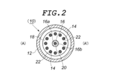
- the ceramic porcelain 18 is formed with a central hole 20 through which the heater fixing shaft 16 is inserted and a heater wire holding hole 22 uniformly distributed on the circumference having the same center as the central hole 20.
- the outer diameter of the ceramic porcelain 18 itself or the diameter of its circumscribed circle as seen from the axial direction of the above-mentioned radiation tube 12 is larger than the inner diameter of the above-mentioned radiation tube 12 or the diameter of its inscribed circle. It is characterized in that it is formed so as to be small.
- the present inventors have described this type of electric heating device, that is, an electric heating device in which an insulator such as a heater fixing shaft or a ceramic porcelain and a heater wire are housed in a metal radiant tube to protect them from an external atmosphere. Due to the difference in the thermal expansion rate of each member during heat generation operation or stop cooling, the inner surface of the radiation tube and the peripheral edge of the (mainly) ceramic porcelain contact and slide, and the metal oxidation generated on the inner surface of the radiation tube. Objects will be scraped off and deposited around the heater wire on the ceramic porcelain. Then, as the amount of deposited metal oxide increases, a short circuit occurs between adjacent heater wires. We found that this was a major cause of element failure.
- the outer diameter of the ceramic porcelain 18 itself or the diameter of its circumscribed circle as seen from the axial direction of the radiant tube 12 is larger than the inner diameter of the radiant tube 12 or the diameter of its inscribed circle. Since it is formed so as to be small, the contact between the inner surface of the radiant tube 12 and the peripheral edge of the ceramic porcelain 18 at the time of heat generation operation or stop cooling of the electric heating device can be minimized, and the contact between the two can be minimized. The amount of scraped off metal oxide can be significantly reduced.
- the peripheral portion of the ceramic insulator 18 in contact with the radiation tube 12 is formed in an R shape. In this case, even if the inner surface of the radiation tube 12 and the peripheral edge of the ceramic insulator 18 come into contact with each other, the amount of metal oxide scraped off due to the contact between the two can be further reduced.
- the ceramic insulator 18 into a polygonal shape that is rotationally symmetric in a plan view.
- a gap can always be provided between the two, and the inner surface of the radiation tube 12 is scraped off through the gap. It is possible to reduce the amount of the metal oxide deposited on the ceramic insulator 18 by discharging the metal oxide downward.
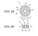
- a concave groove 30 is formed at a position between the heater wire holding holes 22 adjacent to each other in the outer peripheral direction of the central hole 20 on the upper surface of the ceramic insulator 18. It is preferable to install it. In this case, the metal oxide that is scraped off from the inner surface of the radiation tube 12 or is released / dropped and deposited on the ceramic insulator 18 is accommodated in the groove 30. Therefore, it becomes possible to significantly delay the short circuit between the adjacent heater wires 14 due to the metal oxide.
- a substantially vertically steep step portion 32 by forming a wall thickness around the central hole 20 of the ceramic insulator 18.
- the metal oxide scraped off from the inner surface of the radiation tube 12 or released / dropped off is deposited above and below the stepped portion 32, and the adjacent heater wires 14 are connected to each other in the same manner as the above-mentioned concave groove 30. It will be possible to significantly delay the short circuit due to the metal oxide.
- the ceramic insulator 18 is lightened between the heater wire holding holes 22 adjacent to each other in the outer peripheral direction of the central hole 20 and adjacent to each other. It is preferable to dispose one of the heater wires 14 to be lightened. In this case, the adjacent heater wires 14 are supported by different ceramic insulators 18, and the short-circuiting of the adjacent heater wires 14 due to the metal oxide deposited on the ceramic insulator 18 is almost completely eliminated. You will be able to do it.
- FIG. 5A is a plan view showing a ceramic insulator of another embodiment (fourth embodiment) of the present invention.
- FIG. 5B is a cut end view of the BB'line in FIG. 5A.
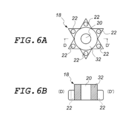
- FIG. 6A is a plan view showing a ceramic insulator of another embodiment (fifth embodiment) of the present invention.
- FIG. 6B is a cross-sectional view taken along the line DD'in FIG. 6A.
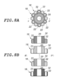
- FIG. 7A is a plan view showing an arrangement state of ceramic insulators of another embodiment (sixth embodiment) of the present invention.
- FIG. 7B is a cross-sectional view taken along the line EE'in FIG. 7A (partially omitted).
- FIG. 8A is a plan view showing an arrangement state of ceramic insulators of another embodiment (seventh embodiment) of the present invention.
- FIG. 8B is a cross-sectional view taken along the line FF'in FIG. 8A (partially omitted).
- FIG. 1 is a vertical cross-sectional view omitting a part of the internal structure (specifically, the heater wire 14 arranged on the front side) in the electric heating device 10 of the present embodiment.
- the electric heating device 10 of the present embodiment is a device used as a heat source for an industrial electric furnace used in various industrial processes, and as shown in this figure, a radiant tube 12, a heater wire 14, and a heater fixed shaft 16 It is roughly composed of a ceramic porcelain 18 and a ceramic porcelain 18.
- the radiation tube 12 is a metal tube in which a heating unit such as a heater wire 14 is housed by closing one end in the longitudinal direction and opening the other end in the longitudinal direction.
- the metal material constituting the radiant tube 12 is appropriately selected according to the usage environment of the electric heating device 10.
- a highly corrosion-resistant metal material such as Hastelloy (registered trademark of Haynes Co., Ltd .; the same applies hereinafter) C22. ..
- a pipe flange 24 is provided on the open end side of the other end in the longitudinal direction of the radiant pipe 12, and the electric heating device 10 can be used as a furnace wall (not shown) of an electric furnace via the pipe flange 24. Be attached to.
- the radiation tube 12 is formed of a cylindrical body is shown, but the form of the radiation tube 12 is not limited to this, and if necessary, for example, a polygonal cylinder or the like. May be.
- the heater wire 14 is a long heating resistor made of a metal wire such as a nichrome wire or a Kanthal (registered trademark of Sandvik) wire, or a rod-shaped heating element such as SiC. By passing an electric current, the temperature rises to about 800 ° C to 1400 ° C depending on the type of material and the like. As shown in FIG. 2, in the present embodiment, twelve heater wires 14 are installed around the axis of the heater fixing shaft 16 described later at equal intervals, and the conductors are conductive such as Ni (nickel). They are electrically connected in series via a heater crossover plate (not shown) made of a material with excellent corrosion resistance. A plug 26 is attached to one end of the heater wire 14 in the longitudinal direction (lower end in the embodiment of FIG.
- the heater wire 14 is formed of a metal wire, the shape may be a straight single wire (rod shape) as shown in the illustrated embodiment, or the heater wire 14 may be a spirally wound metal wire. May be good.
- the heater fixing shaft 16 is a long member that supports the heater wire 14 via a ceramic insulator 18 described later, and functions as a core material 16a made of a stainless round bar and an insulator that covers the surface of the core material 16a. It is composed of a ceramic insulating cladding tube 16b.
- the heater fixing shaft 16 is arranged on the central axis of the radiation tube 12, and a plurality of ceramic insulators 18, which will be described later, are attached at predetermined intervals.
- the ceramic insulator 18 is a disk-shaped instrument that insulates and fixes the heater wire 14 at a predetermined position in the radiation tube 12 in cooperation with the heater fixing shaft 16.
- the ceramic insulator 18 is formed into a perfect circular shape in a plan view, and as shown in FIG. 1, the shape of the peripheral edge thereof is the center “C” in the thickness direction. Is the maximum outer diameter, and the outer diameter is gradually reduced toward both front and back sides. That is, the entire peripheral surface is formed in an R shape.
- a central hole 20 through which the heater fixing shaft 16 is inserted is inserted in the center thereof, and 12 heater wires are held evenly distributed on the circumference having the same center as the central hole 20.
- a hole 22 is formed.
- the outer diameter of the ceramic insulator 18 seen from the axial direction of the radiation tube 12 is set to be smaller than the inner diameter of the radiation tube 12, and the heater wire 14 is not operated at room temperature (normal temperature state). That is, in the normal state), the size is such that the two do not come into contact with each other.
- the entire peripheral surface of the porcelain 18 is formed in an R shape, the stress applied to the inner surface of the radiating tube 12 by the peripheral surface of the ceramic porcelain 18 when the inner surface of the radiation tube 12 and the peripheral edge of the ceramic porcelain 18 come into contact with each other. Can be alleviated and the amount of scraped off metal oxide can be significantly reduced. Therefore, the occurrence of element failure that causes various troubles can be delayed as much as possible, and stable operation for a long period of time becomes possible.
- the heater wire 14 and the heater fixing shaft 16 are in the shape of a round bar, but the shape of the heater wire 14 and the heater fixing shaft 16 is not limited to this.
- a square rod-shaped one may be used.
- the shape of the central hole 20 and the heater wire holding hole 22 of the ceramic insulator 18 is not a perfect circular shape, but a shape that follows the outer shape of the square rod-shaped heater wire 14 and the heater fixing shaft 16.
- the case where the radiation tube 12 is formed of a cylindrical body and the ceramic porcelain 18 is formed into a perfect circular shape in a plan view is shown.
- 18 may be formed into a polygonal shape in a plan view as described later.
- the ceramic insulator 18 may be formed into an elliptical shape in a plan view.
- the diameter of the circumscribed circle of the ceramic porcelain 18 seen from the axial direction of the radiation tube 12 is formed to be smaller than the diameter of the inscribed circle of the radiation tube 12. Will be done.
- FIG. 1 a case is shown in which the pipe flange 24 and the plug 26 are arranged under the radiation pipe 12 and the electric heating device 10 is erected in an electric furnace (not shown).
- the installation mode of the electric heating device 10 of the present invention in the electric furnace is not limited to this.
- the electric heating device 10 may be vertically installed in an electric furnace (not shown) by arranging it on the upper side.
- the plugs 26 may be provided at both ends in the longitudinal direction of the radiant tube 12 and the power may be supplied from both sides in the longitudinal direction of the radiant tube 12. Further, in the embodiment of FIG.
- the structure in which the tip (upper end) of the heater wire 14 reaches the ceiling surface of the radiation tube 12 is shown, but the tip end (upper end) of the heater wire 14 and the radiation tube 12 are shown. It may have a structure in which a space is provided between the ceiling surface and the ceiling surface. The same applies to this point when the top and bottom of the electric heating device 10 are reversed as described above.
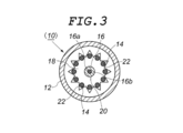
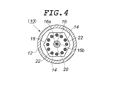
- the ceramic porcelain 18 is formed in a perfect circular shape in a plan view, but the ceramic porcelain 18 is, for example, rotationally symmetric in a plan view as shown in FIG. It is more preferable to have a polygonal shape that is rotationally symmetric in a plane view, such as an object formed in a star-shaped polygonal shape or an object having a regular hexagonal shape in a plan view as shown in FIG. Further, as described above, the ceramic insulator 18 may be formed into an elliptical shape in a plan view. However, even in these cases, it is preferable that the shape of the peripheral edge of the ceramic insulator 18 is an R shape in the entire peripheral surface or a part in contact with the inner surface of the radiation tube 12.
- the surface (upper surface) of the ceramic insulator 18 is formed on a plane, but for example, as shown in FIG. 5, they are adjacent to each other in the outer peripheral direction of the central hole 20 on the upper surface of the ceramic insulator 18. It is preferable to dig a concave groove 30 at a position between the heater wire holding holes 22.
- the generation of metal oxides due to rubbing between the ceramic porcelain 18 and the inner surface of the radiation tube 12 can be dealt with by the above-mentioned technique, but in addition to rubbing, powder caused by oxidation of the metal surface due to high temperature is generated, and this metal is generated. Oxide powder may be released / dropped from the surface of the radiation tube 12 and deposited on the surface of the ceramic porcelain 18.
- the adjacent heater wires 14 are short-circuited by the metal oxide deposited on the ceramic insulator 18, which causes an electric leakage.
- the adjacent heaters are formed. It is possible to significantly delay the short circuit between the wires 14 due to the metal oxide powder.
- each of the ceramic insulators 18 holds all of the plurality (12) heater wires 14 arranged so as to be parallel to each other by the heater wire holding holes 22.
- the space between the heater wire holding holes 22 adjacent to each other in the outer peripheral direction of the central hole 20 of the ceramic insulator 18 is cut out, and the adjacent heater wires are used.
- one of 14 is arranged in the lightening portion. With this configuration, the adjacent heater wires 14 are supported by different ceramic insulators 18, and the metal oxides deposited on the ceramic insulators 18 cause the adjacent heater wires 14 to be almost completely short-circuited. You will be able to eliminate it.
- a rotationally symmetric ceramic insulator 18 provided with six heater wire holding holes 22 is used, and the ceramic insulator 18 is rotated by 30 ° up and down and arranged. , 12 heater wires 14 are held, but in this embodiment, the gaps between the heater wire holding holes 22 adjacent to each other in the outer peripheral direction of the central hole 20 of the ceramic insulator 18 are lightened and adjacent to each other. Any aspect may be used as long as one of the heater wires 14 is arranged in the lightening portion thereof, and the present invention is not limited to the one shown in the above illustration.
Landscapes
- Resistance Heating (AREA)
Priority Applications (5)
| Application Number | Priority Date | Filing Date | Title |
|---|---|---|---|
| JP2022531198A JP7161816B2 (ja) | 2020-06-18 | 2020-06-18 | 電熱装置 |
| CN202080100953.9A CN115669218A (zh) | 2020-06-18 | 2020-06-18 | 电热装置 |
| US18/000,890 US20240237155A1 (en) | 2020-06-18 | 2020-06-18 | Electric heating device |
| KR1020227041882A KR20230003190A (ko) | 2020-06-18 | 2020-06-18 | 전열 장치 |
| PCT/JP2020/023962 WO2021255893A1 (ja) | 2020-06-18 | 2020-06-18 | 電熱装置 |
Applications Claiming Priority (1)
| Application Number | Priority Date | Filing Date | Title |
|---|---|---|---|
| PCT/JP2020/023962 WO2021255893A1 (ja) | 2020-06-18 | 2020-06-18 | 電熱装置 |
Publications (1)
| Publication Number | Publication Date |
|---|---|
| WO2021255893A1 true WO2021255893A1 (ja) | 2021-12-23 |
Family
ID=79267657
Family Applications (1)
| Application Number | Title | Priority Date | Filing Date |
|---|---|---|---|
| PCT/JP2020/023962 Ceased WO2021255893A1 (ja) | 2020-06-18 | 2020-06-18 | 電熱装置 |
Country Status (5)
| Country | Link |
|---|---|
| US (1) | US20240237155A1 (enExample) |
| JP (1) | JP7161816B2 (enExample) |
| KR (1) | KR20230003190A (enExample) |
| CN (1) | CN115669218A (enExample) |
| WO (1) | WO2021255893A1 (enExample) |
Cited By (1)
| Publication number | Priority date | Publication date | Assignee | Title |
|---|---|---|---|---|
| JP7140440B1 (ja) * | 2022-01-28 | 2022-09-21 | カンケンテクノ株式会社 | 筒状加熱部と該筒状加熱部を備えた排ガス処理装置 |
Families Citing this family (1)
| Publication number | Priority date | Publication date | Assignee | Title |
|---|---|---|---|---|
| JP7325151B1 (ja) | 2023-04-10 | 2023-08-14 | カンケンテクノ株式会社 | 筒状加熱部と該筒状加熱部を備えた排ガス処理装置 |
Citations (6)
| Publication number | Priority date | Publication date | Assignee | Title |
|---|---|---|---|---|
| JPS5926895U (ja) * | 1982-08-13 | 1984-02-20 | ミクニ機工株式会社 | チユ−ブヒ−タ用支持碍子 |
| JPS61142685A (ja) * | 1984-12-14 | 1986-06-30 | ニムラ鋼機株式会社 | ラジアントチユ−ブ式ヒ−タ− |
| JPH02143795U (enExample) * | 1989-05-02 | 1990-12-06 | ||
| JPH07312278A (ja) * | 1993-04-02 | 1995-11-28 | Kanthal Gmbh | 産業用電気炉の加熱エレメントにおける発熱抵抗体支持用セラミックディスク |
| JP2011029028A (ja) * | 2009-07-27 | 2011-02-10 | Mikuni Kiko Kk | 炉内加熱ヒータ用碍子およびそれを用いた炉内加熱ヒータ |
| JP5270688B2 (ja) * | 2007-12-10 | 2013-08-21 | サンドビック インテレクチュアル プロパティー アクティエボラーグ | 電熱装置 |
Family Cites Families (3)
| Publication number | Priority date | Publication date | Assignee | Title |
|---|---|---|---|---|
| US2888546A (en) * | 1957-09-16 | 1959-05-26 | Theodore S Kinney | Immersion electric heater |
| US4322606A (en) * | 1980-04-28 | 1982-03-30 | Agf Inc. | Electrical heating element assembly |
| SE526522C2 (sv) * | 2003-06-27 | 2005-10-04 | Sandvik Intellectual Property | Keramisk stödskiva för värmeledare |
-
2020
- 2020-06-18 CN CN202080100953.9A patent/CN115669218A/zh active Pending
- 2020-06-18 JP JP2022531198A patent/JP7161816B2/ja active Active
- 2020-06-18 KR KR1020227041882A patent/KR20230003190A/ko active Pending
- 2020-06-18 US US18/000,890 patent/US20240237155A1/en active Pending
- 2020-06-18 WO PCT/JP2020/023962 patent/WO2021255893A1/ja not_active Ceased
Patent Citations (6)
| Publication number | Priority date | Publication date | Assignee | Title |
|---|---|---|---|---|
| JPS5926895U (ja) * | 1982-08-13 | 1984-02-20 | ミクニ機工株式会社 | チユ−ブヒ−タ用支持碍子 |
| JPS61142685A (ja) * | 1984-12-14 | 1986-06-30 | ニムラ鋼機株式会社 | ラジアントチユ−ブ式ヒ−タ− |
| JPH02143795U (enExample) * | 1989-05-02 | 1990-12-06 | ||
| JPH07312278A (ja) * | 1993-04-02 | 1995-11-28 | Kanthal Gmbh | 産業用電気炉の加熱エレメントにおける発熱抵抗体支持用セラミックディスク |
| JP5270688B2 (ja) * | 2007-12-10 | 2013-08-21 | サンドビック インテレクチュアル プロパティー アクティエボラーグ | 電熱装置 |
| JP2011029028A (ja) * | 2009-07-27 | 2011-02-10 | Mikuni Kiko Kk | 炉内加熱ヒータ用碍子およびそれを用いた炉内加熱ヒータ |
Cited By (5)
| Publication number | Priority date | Publication date | Assignee | Title |
|---|---|---|---|---|
| JP7140440B1 (ja) * | 2022-01-28 | 2022-09-21 | カンケンテクノ株式会社 | 筒状加熱部と該筒状加熱部を備えた排ガス処理装置 |
| WO2023145022A1 (ja) * | 2022-01-28 | 2023-08-03 | カンケンテクノ株式会社 | 筒状加熱部と該筒状加熱部を備えた排ガス処理装置 |
| KR20230117326A (ko) * | 2022-01-28 | 2023-08-08 | 칸켄 테크노 가부시키가이샤 | 통형상 가열부와 상기 통형상 가열부를 구비한 배기 가스 처리 장치 |
| KR102569040B1 (ko) | 2022-01-28 | 2023-08-22 | 칸켄 테크노 가부시키가이샤 | 통형상 가열부와 상기 통형상 가열부를 구비한 배기 가스 처리 장치 |
| US12161964B2 (en) | 2022-01-28 | 2024-12-10 | Kanken Techno Co., Ltd. | Cylindrical heating unit and exhaust gas processing device including the cylindrical heating unit |
Also Published As
| Publication number | Publication date |
|---|---|
| KR20230003190A (ko) | 2023-01-05 |
| US20240237155A1 (en) | 2024-07-11 |
| JPWO2021255893A1 (enExample) | 2021-12-23 |
| CN115669218A (zh) | 2023-01-31 |
| JP7161816B2 (ja) | 2022-10-27 |
Similar Documents
| Publication | Publication Date | Title |
|---|---|---|
| JP6049225B2 (ja) | ガラス製造装置および方法 | |
| CN110527984B (zh) | 加热炉体和半导体设备 | |
| TWI353631B (en) | Wafer heating device and semiconductor equipment | |
| TWI612177B (zh) | 加熱裝置 | |
| WO2021255893A1 (ja) | 電熱装置 | |
| CN219780426U (zh) | 电加热器系统 | |
| KR20070094445A (ko) | 반도체 뱃치 가열 어셈블리 | |
| TW201520366A (zh) | 用於cvd反應器之基座的加熱裝置 | |
| KR20180098428A (ko) | 고온 증발원용 히터 | |
| US3327041A (en) | Radiant heat reflecting device | |
| JP2022539906A (ja) | 電流フィードスルー | |
| CN106165080A (zh) | 用于加热单元的支撑系统 | |
| JP6853459B1 (ja) | 電熱装置 | |
| JP5272485B2 (ja) | 基板支持部材 | |
| JP2604944B2 (ja) | 半導体ウエハー加熱装置 | |
| JP3655308B2 (ja) | 電気的溶融装置 | |
| CN114207397A (zh) | 温度传感器及加热器单元 | |
| US20060193366A1 (en) | Heating element structure with efficient heat generation and mechanical stability | |
| JPS6341753Y2 (enExample) | ||
| US4499334A (en) | Heat resistant sheathed insulated electrical conductors | |
| CN110418576B (zh) | 用于丝网加热器的改进的电能传递系统 | |
| US3285593A (en) | Furnace heat shield | |
| JP2015023152A (ja) | 気相成長装置及び気相成長用加熱装置 | |
| CN205808112U (zh) | 一种热处理炉用加热体 | |
| JPH07161725A (ja) | ウエハー加熱装置および加熱装置用電極部材 |
Legal Events
| Date | Code | Title | Description |
|---|---|---|---|
| 121 | Ep: the epo has been informed by wipo that ep was designated in this application |
Ref document number: 20940715 Country of ref document: EP Kind code of ref document: A1 |
|
| ENP | Entry into the national phase |
Ref document number: 2022531198 Country of ref document: JP Kind code of ref document: A |
|
| ENP | Entry into the national phase |
Ref document number: 20227041882 Country of ref document: KR Kind code of ref document: A |
|
| WWE | Wipo information: entry into national phase |
Ref document number: 18000890 Country of ref document: US |
|
| NENP | Non-entry into the national phase |
Ref country code: DE |
|
| 122 | Ep: pct application non-entry in european phase |
Ref document number: 20940715 Country of ref document: EP Kind code of ref document: A1 |