WO2021255777A1 - 空気調和機 - Google Patents
空気調和機 Download PDFInfo
- Publication number
- WO2021255777A1 WO2021255777A1 PCT/JP2020/023365 JP2020023365W WO2021255777A1 WO 2021255777 A1 WO2021255777 A1 WO 2021255777A1 JP 2020023365 W JP2020023365 W JP 2020023365W WO 2021255777 A1 WO2021255777 A1 WO 2021255777A1
- Authority
- WO
- WIPO (PCT)
- Prior art keywords
- valve
- valves
- shielding
- indoor
- refrigerant
- Prior art date
- Legal status (The legal status is an assumption and is not a legal conclusion. Google has not performed a legal analysis and makes no representation as to the accuracy of the status listed.)
- Ceased
Links
Images




Classifications
-
- F—MECHANICAL ENGINEERING; LIGHTING; HEATING; WEAPONS; BLASTING
- F24—HEATING; RANGES; VENTILATING
- F24F—AIR-CONDITIONING; AIR-HUMIDIFICATION; VENTILATION; USE OF AIR CURRENTS FOR SCREENING
- F24F11/00—Control or safety arrangements
- F24F11/70—Control systems characterised by their outputs; Constructional details thereof
-
- F—MECHANICAL ENGINEERING; LIGHTING; HEATING; WEAPONS; BLASTING
- F25—REFRIGERATION OR COOLING; COMBINED HEATING AND REFRIGERATION SYSTEMS; HEAT PUMP SYSTEMS; MANUFACTURE OR STORAGE OF ICE; LIQUEFACTION SOLIDIFICATION OF GASES
- F25B—REFRIGERATION MACHINES, PLANTS OR SYSTEMS; COMBINED HEATING AND REFRIGERATION SYSTEMS; HEAT PUMP SYSTEMS
- F25B13/00—Compression machines, plants or systems, with reversible cycle
-
- F—MECHANICAL ENGINEERING; LIGHTING; HEATING; WEAPONS; BLASTING
- F25—REFRIGERATION OR COOLING; COMBINED HEATING AND REFRIGERATION SYSTEMS; HEAT PUMP SYSTEMS; MANUFACTURE OR STORAGE OF ICE; LIQUEFACTION SOLIDIFICATION OF GASES
- F25B—REFRIGERATION MACHINES, PLANTS OR SYSTEMS; COMBINED HEATING AND REFRIGERATION SYSTEMS; HEAT PUMP SYSTEMS
- F25B6/00—Compression machines, plants or systems, with several condenser circuits
- F25B6/02—Compression machines, plants or systems, with several condenser circuits arranged in parallel
Definitions
- This disclosure relates to a multi-type air conditioner to which multiple indoor units can be connected.
- a multi-type air conditioner in which a plurality of indoor units are connected to one outdoor unit is known.
- the state of each indoor unit may differ depending on the air conditioning condition of the air-conditioned space in which each indoor unit is installed. For example, while the outdoor unit is operating in the heating operation, the indoor unit whose room temperature in the air-conditioning target space does not reach the set value is in operation, and the indoor unit in which the room temperature in the air-conditioning target space meets the set value is thermo-off or Operation may be stopped when the switch is turned off. Normally, the electronic expansion valve of the stopped indoor unit is closed.
- the electronic expansion valve performing the expansion action is only the one provided on the liquid side of the outdoor heat exchanger. It becomes. Therefore, a high-pressure gas refrigerant exists in the indoor heat exchanger of the indoor unit that is stopped. Even if the indoor blower is stopped, the high-pressure gas refrigerant causes convection heat transfer with the indoor air in the indoor heat exchanger, so that the high-pressure gas refrigerant dissipates heat, condenses and is stopped as a liquid refrigerant. It will accumulate in the indoor unit. As a result, there is a shortage of refrigerant for the refrigeration cycle formed in the air conditioner.
- Patent Document 1 provides solenoid valves between the indoor unit and the gas side connection pipe and between the indoor unit and the liquid side connection pipe, and controls the opening and closing of these solenoid valves during heating operation. A configuration for preventing the accumulation of refrigerant in the heat exchanger of the indoor unit that is thermo-off is described.
- the air conditioner of Patent Document 1 it is the inside of the indoor heat exchanger that the accumulation of the refrigerant can be suppressed by controlling the opening and closing of the solenoid valve described above.
- the configuration of the air conditioner of Patent Document 1 it is difficult to suppress the accumulation of the refrigerant generated in the piping portion between the branch portion and the solenoid valve in the branch pipe branching from the gas side connection pipe to each indoor unit. Is.
- This disclosure is made against the background of the above-mentioned problems, and provides an air conditioner that can improve the operation efficiency during the heating operation and suppress the accumulation of the refrigerant in the piping.
- the air conditioner according to the present disclosure includes a plurality of indoor units having an indoor heat exchanger, an outdoor unit having a compressor and an outdoor heat exchanger, a gas main pipe connected to the outdoor unit, and the outdoor unit.
- the liquid main pipe connected to the liquid main pipe, a plurality of gas branch pipes branched from the gas main pipe and connected to the plurality of indoor units, and a plurality of gas branch pipes branched from the liquid main pipe and connected to the plurality of indoor units.
- a plurality of expansion valves provided on the pipe and a first control means are provided, and the indoor heat exchanger, the compressor, the outdoor heat exchanger, and the plurality of the indoor heat exchangers of the indoor unit are provided.
- a refrigerant circuit is formed by one shield valve, a plurality of the second shield valves, and a plurality of the expansion valves, and the first control means operates among the plurality of indoor units during the heating operation.
- the first shield valve connected to the indoor unit and the second shield valve are configured to be closed.
- the first shielding valve and the second shielding valve connected to the indoor unit whose operation is stopped among the plurality of indoor units are closed. Therefore, since the refrigerant is sealed in the pipe connecting the first shield valve, the indoor heat exchanger of the indoor unit whose operation is stopped, and the second shield valve, it is possible to prevent the liquid refrigerant from flowing into this pipe. Will be done. As a result, the accumulation of the liquid refrigerant and the heat dissipation loss of the refrigerant in the piping are suppressed, and the efficiency of the heating operation is improved.
- the air conditioner shown in the drawings shows an example of the equipment to which the air conditioner of the present disclosure is applied, and the air conditioner shown in the drawings does not limit the applicable equipment of the present disclosure. ..
- terms indicating directions for example, “top”, “bottom”, “right”, “left”, “front”, “rear”, etc.
- those having the same reference numerals are the same or equivalent thereof, which are common to the whole text of the specification. In each drawing, the relative dimensional relationship or shape of each component may differ from the actual one.
- FIG. 1 is a system configuration diagram of an air conditioner according to the first embodiment of the present disclosure.
- the air conditioner 1 includes a branching device 10, an outdoor unit 20, a plurality of indoor units 30, and a plurality of remote controllers 60.
- the air conditioner 1 is a multi-type air conditioner for buildings in which a plurality of indoor units 30 are connected to the outdoor unit 20.
- the three indoor units 30 are connected to the outdoor unit 20 via the branching device 10.
- A, B, and C are added to the end of each reference numeral.
- a plurality of indoor units may be collectively referred to as an indoor unit 30, and a plurality of remote controllers may be collectively referred to as a remote controller 60.
- the outdoor unit 20 has an outdoor heat exchanger 21, a compressor 22, a flow path switching unit 23, and an outdoor unit control means 24.
- the outdoor unit control means 24 corresponds to the second control means of the present disclosure.
- the compressor 22 is a variable capacity compressor in which the rotation speed is controlled by an inverter (not shown) and the operating capacity is variable.
- the outdoor heat exchanger 21 exchanges heat between the outside air supplied by an outdoor fan (not shown) and the refrigerant.
- the flow path switching unit 23 changes the flow of the refrigerant in the refrigerant circuit formed in the air conditioner 1 according to the heating operation and the cooling operation, and is, for example, a four-way valve. In FIG. 1, the flow of the refrigerant during the heating operation is indicated by a solid arrow, and the flow of the refrigerant during the cooling operation is indicated by a dotted arrow.
- Each of the three indoor units 30 has an indoor heat exchanger 31 and an indoor unit control means 32.
- the indoor unit 30 is a type of indoor unit that does not have a built-in electronic expansion valve.
- the indoor unit 30A has an indoor heat exchanger 31A and an indoor unit control means 32A
- the indoor unit 30B has an indoor heat exchanger 31B and an indoor unit control means 32B
- the indoor unit 30C has an indoor heat exchanger 31C.
- the indoor unit control means 32C The indoor heat exchanger 31A exchanges heat between the air supplied by the indoor fan (not shown) and the refrigerant.
- the indoor heat exchanger 31B exchanges heat between the air supplied by the indoor fan (not shown) and the refrigerant.
- the indoor heat exchanger 31C exchanges heat between the air supplied by the indoor fan (not shown) and the refrigerant.
- the branching device 10 is provided between the outdoor unit 20 and the indoor unit 30A, the indoor unit 30B, and the indoor unit 30C.
- the branching device 10 includes a plurality of first shielding valves 11, a plurality of second shielding valves 12, a plurality of expansion valves 13, and a branching device control means 100.
- the expansion valve 13 is an electronic expansion valve.
- the branching device control means 100 corresponds to the first control means of the present disclosure. In the following description, when each of the plurality of first shielding valves 11 is referred to, A, B, and C are added to the end of each reference numeral. The same applies to the plurality of second shielding valves 12 and the plurality of expansion valves 13.
- the plurality of first shield valves are collectively referred to as the first shield valve 11, the plurality of second shield valves are collectively referred to as the second shield valve, and the plurality of expansion valves 13 are collectively referred to as the expansion valve 13.
- the first shielding valve 11, the second shielding valve 12, and the expansion valve 13 are housed in a single housing 14.
- the gas main pipe 40 and the liquid main pipe 50 are connected to the outdoor unit 20.
- the discharge side of the compressor 22 is connected to the flow path switching unit 23, and the flow path switching unit 23 is connected to the gas main pipe 40.
- One of the outdoor heat exchangers 21 is connected to the flow path switching unit 23, and the other is connected to the liquid main pipe 50.
- a plurality of gas branch pipes 41 are branched from the gas main pipe 40, and a plurality of liquid branch pipes 51 are branched from the liquid main pipe 50.
- the three indoor units 30A, 30B, and 30C correspond to the three gas branch pipes 41A, 41B, and 41C, and the three liquid branch pipes 51A, 51B, and 51C are branched.
- A, B, and C are added to the end of each reference numeral.
- a plurality of gas branch pipes may be collectively referred to as a gas branch pipe 41, and a plurality of liquid branch pipes may be collectively referred to as a liquid branch pipe 51.
- the first shielding valve 11A is connected to the gas branch pipe 41A
- the first shielding valve 11B is connected to the gas branch pipe 41B
- the first shielding valve 11C is connected to the gas branch pipe 41C. There is.
- the second shielding valve 12A and the expansion valve 13A are connected to the liquid branch pipe 51A.
- the second shielding valve 12A is arranged so as to be located downstream of the expansion valve 13A in the flow of the refrigerant in the case of heating operation.
- a second shielding valve 12B and an expansion valve 13B are connected to the liquid branch pipe 51B.
- the second shielding valve 12B is arranged so as to be located downstream of the expansion valve 13B in the flow of the refrigerant in the case of heating operation.
- the second shielding valve 12C and the expansion valve 13C are connected to the liquid branch pipe 51C.
- the second shielding valve 12C is arranged so as to be located downstream of the expansion valve 13C in the flow of the refrigerant in the case of heating operation.
- a gas branch pipe 41A and a liquid branch pipe 51A are connected to the indoor heat exchanger 31A.
- a gas branch pipe 41B is connected to one of the indoor heat exchangers 31B, and a liquid branch pipe 51B is connected to the other.
- a gas branch pipe 41C is connected to one of the indoor heat exchangers 31C, and a liquid branch pipe 51C is connected to the other.
- the liquid branch pipe 51 forms a refrigerant circuit.
- the branching device 10 and the outdoor unit 20 are connected by an outdoor transmission line 70.
- a signal is transmitted and received between the branch device control means 100 and the outdoor unit 20 via the outdoor transmission line 70.
- the branching device 10 and the indoor units 30A, 30B, and 30C are connected by an indoor transmission line 80. Signals are transmitted and received between the branch device control means 100 and the indoor units 30A, 30B, and 30C via the indoor transmission line 80.
- a remote controller 60A is connected to the indoor unit 30A via the remote controller line 26A, and signals are transmitted and received between the indoor unit control means 32A and the remote controller 60A via the remote controller line 26A.
- a remote controller 60B is connected to the indoor unit 30B via the remote controller line 26B, and signals are transmitted and received between the indoor unit control means 32B and the remote controller 60B via the remote controller line 26B.
- a remote controller 60C is connected to the indoor unit 30C via the remote controller line 26C, and signals are transmitted and received between the indoor unit control means 32C and the remote controller 60C via the remote controller line 26C.
- the flow path switching unit 23 is switched to the state shown by the solid line by the outdoor unit control means 24.
- the gas refrigerant is guided to the branching device 10 via the gas main pipe 40 via the flow path switching unit 23.
- the gas refrigerant passes through the first shielding valve 11 and is guided to the indoor unit 30.
- the gas refrigerant branches by the gas branch pipes 41A, 41B, and 41C, and passes through the first shielding valves 11A, 11B, and 11C. , Guided to the indoor units 30A, 30B, and 30C.
- the gas refrigerant guided to the indoor unit 30 exchanges heat with the indoor air in the indoor heat exchanger 31 and is condensed to become a liquid refrigerant.
- the liquid refrigerant flowing out of the indoor heat exchanger 31 is guided to the expansion valve 13 of the branching device 10 via the liquid branch pipe 51.
- the liquid refrigerant is decompressed by the expansion valve 13 to enter a gas-liquid two-phase state.
- the refrigerant in the gas-liquid two-phase state passes through the second shielding valve 12 and is guided to the outdoor heat exchanger 21.
- the refrigerant exchanges heat with the outdoor air and evaporates to become a gas refrigerant.
- the gas refrigerant flowing out of the outdoor heat exchanger 21 is sucked into the compressor 22 via the flow path switching unit 23.
- the flow path switching unit 23 is switched to the state indicated by the dotted arrow by the outdoor unit control means 24.
- the gas refrigerant is guided to the outdoor heat exchanger 21 via the flow path switching unit 23.
- the outdoor heat exchanger 21 the gas refrigerant exchanges heat with the outdoor air and is condensed to become a liquid refrigerant.
- the liquid refrigerant flowing out of the outdoor heat exchanger 21 is guided to the branching device 10 via the liquid main pipe 50.
- the liquid refrigerant passes through the second shielding valve 12, is depressurized by the expansion valve 13, and is guided to the indoor unit 30 via the liquid branch pipe 51.
- the liquid refrigerant is branched by the liquid branch pipes 51A, 51B, and 51C according to the operating state of the indoor units 30A, 30B, and 30C, and is guided to the indoor units 30A, 30B, and 30C.
- the refrigerant guided to the indoor unit 30 exchanges heat with the indoor air in the indoor heat exchanger 31 and evaporates to become a low-pressure gas refrigerant.
- the low-pressure gas refrigerant flowing out of the indoor heat exchanger 31 passes through the first shielding valve 11 of the branching device 10 via the gas branch pipe 41, and is guided to the outdoor unit 20 via the gas main pipe 40.
- the low-pressure gas refrigerant guided to the outdoor unit 20 is sucked into the compressor 22 via the flow path switching unit 23.
- FIG. 2 is a configuration diagram of a branching device of an air conditioner according to the first embodiment of the present disclosure.
- the branching device 10 has a branching device control means 100.
- the branch device control means 100 is composed of dedicated hardware or a CPU (Central Processing Unit) that executes a program stored in a memory.
- the CPU is also referred to as a central processing unit, a processing unit, an arithmetic unit, a microprocessor, a microcomputer, or a processor.
- branch device control means 100 When the branch device control means 100 is dedicated hardware, the branch device control means 100 may use, for example, a single circuit, a composite circuit, an ASIC (Application Specific Integrated Circuit), an FPGA (Field-Programmable Gate Array), or these. The combination is applicable.
- Each of the functional units realized by the branch device control means 100 may be realized by individual hardware, or each functional unit may be realized by one hardware.
- each function executed by the branch device control means 100 is realized by software, firmware, or a combination of software and firmware.
- Software and firmware are written as programs and stored in memory.
- the CPU realizes each function of the branch device control means 100 by reading and executing the program stored in the memory.
- the memory is a non-volatile or volatile semiconductor memory such as, for example, RAM, ROM, flash memory, EPROM, or EEPROM.
- a part of the function of the branching device control means 100 may be realized by dedicated hardware, and a part may be realized by software or firmware.
- the indoor unit control means 32A, the indoor unit control means 32B, the indoor unit control means 32C, and the outdoor control means 33, which are shown in FIG. 1, are also stored in dedicated hardware or memory in the same manner as the branch device control means 100. It consists of a CPU that executes a program.
- the branching device control means 100 has the unique address identification means 101, the expansion valve control means 102, the outdoor unit communication means 103, the indoor unit communication means 104, and the first shielding valve as functional units. It has a control means 105 and a second shield valve control means 106.
- the first shield valve control means 105 is connected to the first shield valves 11A, 11B, and 11C by the first shield valve control line 110.
- the second shield valve control means 106 is connected to the second shield valves 12A, 12B, and 12C by the second shield valve control line 111.
- the expansion valve control means 102 is connected to the expansion valves 13A, 13B, and 13C by the expansion valve control line 112.
- a signal is transmitted and received between the outdoor unit communication means 103 and the outdoor unit control means 24 (see FIG. 1) via the outdoor transmission line 70.
- a signal is transmitted and received between the indoor unit communication means 104 and the indoor unit control means 32 (see FIG. 1) via the indoor transmission line 80.
- the indoor unit communication means 104 receives the indoor unit information output from the indoor unit control means 32 of the indoor unit 30. That is, the indoor unit information output by the indoor unit control means 32A of the indoor unit 30A, the indoor unit information output by the indoor unit control means 32B of the indoor unit 30B, and the indoor unit information output by the indoor unit control means 32C of the indoor unit 30C. Is input to the indoor unit communication means 104.
- the indoor unit information includes operation information indicating whether the indoor unit 30 is in the thermo-on state or the thermo-off state.
- the unique address identification means 101 adds the unique address of the indoor unit 30 that outputs the indoor unit information to the indoor unit information received by the indoor unit communication means 104. That is, in the unique address identification means 101, the unique address of the indoor unit 30A is added to the indoor unit information output from the indoor unit control means 32A, and the indoor unit information 30B is added to the indoor unit information output from the indoor unit control means 32B. The unique address of the indoor unit 30C is added to the indoor unit information output from the indoor unit control means 32C.
- the indoor unit information to which the unique address is added by the unique address identification means 101 is transmitted from the outdoor unit communication means 103 to the outdoor unit control means 24.
- the outdoor unit communication means 103 controls the outdoor unit by controlling the first shield valves 11A, 11B, and 11C, the second shield valves 12A, 12B, and 12C, and the signals instructing the opening and closing of the expansion valves 13A, 13B, and 13C. Received from means 24.
- the first shield valve control means 105 reaches the first shield valves 11A, 11B, and 11C via the first shield valve control line 110 based on the signal received by the outdoor unit communication means 103 from the outdoor unit control means 24. Outputs a signal instructing opening and closing.
- the second shield valve control means 106 reaches the second shield valves 12A, 12B, and 12C via the second shield valve control line 111 based on the signal received by the outdoor unit communication means 103 from the outdoor unit control means 24. Outputs a signal instructing opening and closing.
- the expansion valve control means 102 is a signal instructing the expansion valves 13A, 13B, and 13C via the expansion valve control line 112 based on the signal received from the outdoor unit control means 24 by the outdoor unit communication means 103. Is output.
- FIG. 3 is a flowchart showing a processing procedure for transmitting indoor unit information in the air conditioner of the present disclosure from the indoor unit to the outdoor unit.
- the remote control signal is transmitted from the remote control 60 operated by the user to the indoor unit 30 via the remote control line 26.
- the remote control signal includes a command to start or stop the operation of the indoor unit 30.
- the remote control signal is received by the indoor unit control means 32 of the indoor unit 30.
- the indoor unit control means 32 transmits the received indoor unit information to the branching device 10.
- the indoor unit information includes operation status information and thermostat status information.
- the operation state information is the operation information of the indoor unit corresponding to the command included in the received remote control signal, that is, the information indicating whether the indoor unit 30 is operating or stopped. When the indoor unit 30 is in operation, it is in a switch-on state, and when it is stopped, it is in a switch-off state.
- the thermo-state information is information indicating whether the indoor unit 30 is in the thermo-on state or the thermo-off state.
- thermo-on state is a state in which the temperature of the air-conditioning target space of the indoor unit 30 has not reached the set temperature and the indoor unit 30 is operating.
- thermo-off state is a state in which the temperature of the air-conditioning target space of the indoor unit 30 has reached the set temperature and the indoor unit 30 is not operating.
- step S104 the indoor unit communication means 104 of the branch device control means 100 receives the indoor unit information.
- step S105 the unique address identification means 101 of the branching device control means 100 adds the unique address of the indoor unit 30 to the received indoor unit information.
- step S106 the indoor unit information to which the unique address is added is transmitted from the branch device control means 100 to the outdoor unit 20 via the outdoor unit communication means 103.
- step S107 the outdoor unit control means 24 of the outdoor unit 20 receives the indoor unit information output from the branch device control means 100.
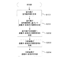
- FIG. 4 is a flowchart showing a control procedure of the first shield valve and the second shield valve in the air conditioner of the present disclosure.
- Step S107 in FIG. 4 is the same process as step S107 in FIG. 3 described above, and is a process in which the outdoor unit control means 24 of the outdoor unit 20 receives the indoor unit information output from the branch device control means 100. Is.
- step S201 the outdoor unit control means 24 of the outdoor unit 20 executes a subroutine for determining the opening and closing of the first shielding valve 11 and the second shielding valve 12.
- FIG. 5 is a flowchart showing a processing procedure for determining the opening / closing of the first shielding valve and the second shielding valve in the air conditioner of the present disclosure. That is, FIG. 5 shows a control procedure of the subroutine of step S201 of FIG. 4 executed by the outdoor unit control means 24 of the outdoor unit 20. In step S301, the outdoor unit control means 24 reads the operation state information and the thermo state information of the indoor unit 30 from the received indoor unit information.
- step S302 the outdoor unit control means 24 checks whether or not the indoor unit 30 is in operation based on the operation state information read in step S301. When it is confirmed that the indoor unit 30 is stopped, the process proceeds to step S303.
- step S303 the outdoor unit control means 24 is connected to the indoor unit 30 which is stopped because it is not necessary to circulate the refrigerant to the indoor unit 30 which is stopped, that is, in the switch-off state. It is determined to close the valve 11 and the second shielding valve 12. That is, the outdoor unit control means 24 determines to close the first shielding valve 11A and the second shielding valve 12A when the indoor unit 30A is stopped, and the first shielding valve when the indoor unit 30B is stopped. It is determined to close the 11B and the second shielding valve 12B, and when the indoor unit 30C is stopped, the closing of the first shielding valve 11C and the second shielding valve 12C is determined.
- step S304 the outdoor unit control means 24 confirms whether or not the indoor unit 30 confirmed to be in operation in step S302 is thermo-on based on the thermo state information read in step S301.
- step S305 The case of proceeding to step S305 is a case where the indoor unit 30 is in operation and is thermo-on, and the air conditioning process by the indoor unit 30 is in operation. Therefore, the outdoor unit control means 24 determines to open the first shield valve 11 and the second shield valve 12.
- the outdoor unit control means 24 determines to open the first shield valve 11A and the second shield valve 12A when the indoor unit 30A is in operation and is thermoon, and when the indoor unit 30B is in operation and is thermoon, the first It is determined to open the shielding valve 11B and the second shielding valve 12B, and when the indoor unit 30C is in operation and is thermo-on, it is determined to open the first shielding valve 11C and the second shielding valve 12C.
- step S304 if it is confirmed in step S304 that the indoor unit 30 is thermo-off, the process proceeds to step S303.
- the case where the indoor unit 30 is thermo-off is a case where the indoor unit 30 is in operation but the air conditioning process by the indoor unit 30 is suspended. Therefore, the process proceeds to step S303, and the outdoor unit control means 24 determines that the first shield valve 11 and the second shield valve 12 are closed as described above.
- step S303 When the process of step S303 or step S305 is executed, the subroutine of FIG. 5 ends, and the process proceeds to step S202 of FIG.
- step S202 the outdoor unit 20 transmits an opening / closing signal for the first shielding valve 11 and the second shielding valve 12 to the branching device control means 100.
- step S203 the outdoor unit communication means 103 of the branch device control means 100 receives the open / close signals of the first shield valve 11 and the second shield valve 12.
- step S204 the first shield valve control means 105 controls the opening / closing of the first shielding valves 11A, 11B, and 11C based on the opening / closing signal of the first shielding valve 11 received by the outdoor unit communication means 103.
- step S204 the second shield valve control means 106 controls the opening / closing of the second shielding valves 12A, 12B, and 12C based on the opening / closing signal of the second shielding valve 12 received by the outdoor unit communication means 103.
- the first shielding valve 11 and the second shielding valve 12 of the indoor unit 30 whose operation is stopped among the plurality of indoor units 30 Is configured to be closed.
- FIG. 6 is a system configuration diagram of the air conditioner according to the first embodiment of the present disclosure.
- FIG. 6 shows a case where the indoor unit 30A is stopped and the indoor units 30B and 30C are in the heating operation.
- the flow of the refrigerant in the air conditioner 1 during the heating operation will be described with reference to FIG.
- the flow of the refrigerant is indicated by a solid arrow, the open first shield valve 11 and the second shield valve 12 are shown in white, and the closed first shield valve 11 and second shield valve 12 are shown. 12 is shown in black. Since the indoor units 30 and 30C are being heated, the first shield valves 11B and 11C and the second shield valves 12B and 12C are open. Therefore, as described above with reference to FIG. 1, the refrigerant flows between the branching device 10, the indoor units 30B and 30C, and the outdoor unit 20.
- the indoor unit 30A is stopped, that is, the operation is stopped, the first shielding valve 11A and the second shielding valve 12A are closed. Therefore, heat exchange is not performed in the indoor heat exchanger 31A, the generation of heat dissipation loss of the refrigerant is suppressed, and the generation of warm air and refrigerant noise from the indoor unit 30A is suppressed. Further, in the first embodiment, the refrigerant is sealed in the pipe connecting the first shielding valve 11A, the indoor heat exchanger 31A, and the second shielding valve 12A.
- the inflow of the liquid refrigerant not only into the indoor heat exchanger 31A but also into the gas branch pipe 41A and the liquid branch pipe 51A connected to the indoor heat exchanger 31A is suppressed.
- the accumulation of the liquid refrigerant in the gas branch pipe 41A and the liquid branch pipe 51A and the generation of heat dissipation loss of the refrigerant are suppressed.
- three indoor units 30 are connected to one outdoor unit 20, but the present invention is not limited to this. Two or four or more indoor units 30 may be connected to the outdoor unit 20.
- the air conditioner 1 of the first embodiment is a multi-type air conditioner
- the above-mentioned processing is also applied to the air conditioner having a configuration in which one indoor unit is connected to the outdoor unit during the heating operation.
- the same processing as above can be performed.
- a gas-side shutoff valve is provided in the gas pipe connecting the outdoor unit and the indoor unit
- a liquid-side shutoff valve is provided in the liquid pipe connecting the outdoor unit and the indoor unit.
- the liquid pipe is provided with an expansion valve. Then, when the heating operation is stopped, the gas side shutoff valve and the liquid side shutoff valve are controlled to be closed.
- This control may be configured to be executed by a control device provided in the outdoor unit, or may be configured to be executed by a control device that controls the entire air conditioner.
- FIG. 7 is a configuration diagram of a branching device of the air conditioner according to the second embodiment of the present disclosure.
- the branching device 130 includes a plurality of first pressure relief valves 15, a plurality of first check valves 16, and a plurality of second pressure relief valves. It has a valve 17 and a plurality of second check valves 18.
- the indoor unit 30A and the gas branch pipe 41A and the liquid branch pipe 51A connected to the indoor unit 30A are typically shown.
- the first shielding valve 11A, the first pressure relief valve 15A, the first check valve 16A, the second shielding valve 12A, the second pressure relief valve 17A, and the second check valve 18A are typically shown. Has been done.
- the first pressure relief valve 15A is connected in parallel with the first shielding valve 11A by the first gas branch sub pipe 42A.
- the second pressure relief valve 17A is connected in parallel with the second shielding valve 12A by the first liquid branch sub-tube 52A.
- the first pressure relief valve 15A is configured to be closed when the refrigerant pressure in the pipe connecting the first shielding valve 11A, the indoor heat exchanger 31A, and the second shielding valve 12A is equal to or lower than the specified pressure. Further, the first pressure relief valve 15A is configured to be opened when the refrigerant pressure in the pipe connecting the first shielding valve 11A, the indoor heat exchanger 31A and the second shielding valve 12A exceeds a specified pressure. ..
- the first pressure relief valve 15A is closed when the refrigerant pressure inside the first gas branch sub pipe 42A is equal to or lower than a preset specified pressure, and the refrigerant pressure inside the first gas branch sub pipe 42A is reduced. It is released when the specified pressure is exceeded.
- the specified pressure is set lower than the withstand voltage capacity of the component forming the refrigerant circuit from the first shield valve 11A to the second shield valve 12A via the indoor heat exchanger 31A.
- the second pressure relief valve 17A is configured to be closed when the refrigerant pressure in the pipe connecting the first shielding valve 11A, the indoor heat exchanger 31A, and the second shielding valve 12A is equal to or lower than the specified pressure.
- the second pressure relief valve 17A is configured to be opened when the refrigerant pressure in the pipe connecting the first shielding valve 11A, the indoor heat exchanger 31A and the second shielding valve 12A exceeds a specified pressure. .. In other words, the second pressure relief valve 17A is closed when the refrigerant pressure inside the first liquid branch sub pipe 52A is equal to or less than the specified pressure, and the refrigerant pressure inside the first liquid branch sub pipe 52A exceeds the specified pressure. Is released.
- the first check valve 16A is connected in parallel with the first shielding valve 11A by the first gas branch sub pipe 42A.
- the first check valve 16A is arranged so that the refrigerant passes only in the direction from the indoor unit 30A to the outdoor unit 20.
- the second check valve 18A is connected in parallel with the second shielding valve 12A via the first liquid branch sub-tube 52A.
- the second check valve 18A is arranged so that the refrigerant passes only in the direction from the indoor unit 30A to the outdoor unit 20.
- the first pressure relief valve 15A and the first check valve 16A have a first gas branch sub-pipe 42A so that the first check valve 16A is located upstream of the first pressure relief valve 15A in the flow of the refrigerant in the heating operation. It is provided in.
- the second pressure relief valve 17A and the second check valve 18A have a first liquid branch sub-pipe 52A so that the second check valve 18A is located upstream of the second pressure relief valve 17A in the flow of the refrigerant in the cooling operation. It is provided in. That is, the first check valve 16A is located closer to the outdoor unit 20 than the first pressure relief valve 15A, and the second check valve 18A is located closer to the outdoor unit 20 than the second pressure relief valve 17A. is doing.
- the refrigerant is sealed in the piping from the first shield valve 11A to the second shield valve 12A via the indoor heat exchanger 31A and inside the indoor heat exchanger 31A. It will be in a stopped state. When the atmospheric temperature rises in this state, the refrigerant pressure of the sealed refrigerant rises accordingly. When the refrigerant pressure exceeds the specified pressures of the first shielding valve 11A and the second shielding valve 12A, the first pressure relief valve 15A and the second pressure relief valve 17A are opened.
- the sealed refrigerant passes through the first pressure relief valve 15A and the first check valve 16A, is guided to the gas main pipe 40, and passes through the second pressure relief valve 17A and the second check valve 18A. Then, it is guided to the liquid main pipe 50.
- the first pressure relief valve 15A is connected in parallel with the first shielding valve 11A
- the second pressure relief valve 17A is connected in parallel with the second shielding valve 12A
- the first pressure relief valve 15A and The second pressure relief valve 17A is configured to open when the refrigerant pressure exceeds a specified pressure.
- the refrigerant pressure may exceed the withstand voltage capacity of the component forming the refrigerant circuit. It is suppressed. As a result, it is possible to suppress damage or burst of the parts forming the refrigerant circuit.
- the effect of suppressing damage or burst of the parts forming the refrigerant circuit can be obtained.
- the first check valve 16A is located closer to the outdoor unit 20 than the first pressure relief valve 15A, and the second check valve 18A is outdoors more than the second pressure relief valve 17A. It is located near the machine 20. Therefore, even if the refrigerant leaks, the refrigerant can be shut off.
- the branching device 130 of the second embodiment includes the gas branch pipe 41B and the liquid branch pipe 51B connected to the indoor unit 30B, and the gas branch pipe 41C and the liquid branch pipe 51C connected to the indoor unit 30C. Also, a refrigerant circuit similar to the gas branch pipe 41A and the liquid branch pipe 51A is formed. Therefore, the same effect as described above can be obtained in the refrigerant circuit to which the indoor unit 30B and the indoor unit 30C are connected.
Landscapes
- Engineering & Computer Science (AREA)
- Mechanical Engineering (AREA)
- General Engineering & Computer Science (AREA)
- Physics & Mathematics (AREA)
- Thermal Sciences (AREA)
- Chemical & Material Sciences (AREA)
- Combustion & Propulsion (AREA)
- Air Conditioning Control Device (AREA)
- Compression-Type Refrigeration Machines With Reversible Cycles (AREA)
Priority Applications (2)
| Application Number | Priority Date | Filing Date | Title |
|---|---|---|---|
| JP2022531105A JP7297160B2 (ja) | 2020-06-15 | 2020-06-15 | 空気調和機 |
| PCT/JP2020/023365 WO2021255777A1 (ja) | 2020-06-15 | 2020-06-15 | 空気調和機 |
Applications Claiming Priority (1)
| Application Number | Priority Date | Filing Date | Title |
|---|---|---|---|
| PCT/JP2020/023365 WO2021255777A1 (ja) | 2020-06-15 | 2020-06-15 | 空気調和機 |
Publications (1)
| Publication Number | Publication Date |
|---|---|
| WO2021255777A1 true WO2021255777A1 (ja) | 2021-12-23 |
Family
ID=79268615
Family Applications (1)
| Application Number | Title | Priority Date | Filing Date |
|---|---|---|---|
| PCT/JP2020/023365 Ceased WO2021255777A1 (ja) | 2020-06-15 | 2020-06-15 | 空気調和機 |
Country Status (2)
| Country | Link |
|---|---|
| JP (1) | JP7297160B2 (https=) |
| WO (1) | WO2021255777A1 (https=) |
Citations (6)
| Publication number | Priority date | Publication date | Assignee | Title |
|---|---|---|---|---|
| JPS5019063U (https=) * | 1973-06-14 | 1975-03-03 | ||
| JPS5045759U (https=) * | 1973-08-10 | 1975-05-08 | ||
| JPS5525749A (en) * | 1978-08-11 | 1980-02-23 | Sharp Kk | Heattpumpptype coolerrheater |
| JPS5635731Y2 (https=) * | 1977-08-19 | 1981-08-22 | ||
| JPH03236555A (ja) * | 1990-02-14 | 1991-10-22 | Toshiba Corp | マルチ空気調和機 |
| JPH03244978A (ja) * | 1990-02-23 | 1991-10-31 | Toshiba Audio Video Eng Corp | 空気調和機 |
-
2020
- 2020-06-15 WO PCT/JP2020/023365 patent/WO2021255777A1/ja not_active Ceased
- 2020-06-15 JP JP2022531105A patent/JP7297160B2/ja active Active
Patent Citations (6)
| Publication number | Priority date | Publication date | Assignee | Title |
|---|---|---|---|---|
| JPS5019063U (https=) * | 1973-06-14 | 1975-03-03 | ||
| JPS5045759U (https=) * | 1973-08-10 | 1975-05-08 | ||
| JPS5635731Y2 (https=) * | 1977-08-19 | 1981-08-22 | ||
| JPS5525749A (en) * | 1978-08-11 | 1980-02-23 | Sharp Kk | Heattpumpptype coolerrheater |
| JPH03236555A (ja) * | 1990-02-14 | 1991-10-22 | Toshiba Corp | マルチ空気調和機 |
| JPH03244978A (ja) * | 1990-02-23 | 1991-10-31 | Toshiba Audio Video Eng Corp | 空気調和機 |
Also Published As
| Publication number | Publication date |
|---|---|
| JP7297160B2 (ja) | 2023-06-23 |
| JPWO2021255777A1 (https=) | 2021-12-23 |
Similar Documents
| Publication | Publication Date | Title |
|---|---|---|
| JP6693312B2 (ja) | 空気調和装置 | |
| JP5182358B2 (ja) | 冷凍装置 | |
| CN106152312B (zh) | 空气调节装置的室外机和空气调节装置 | |
| JP6300954B2 (ja) | 空気調和装置 | |
| WO2018185841A1 (ja) | 冷凍サイクル装置 | |
| KR100757442B1 (ko) | 공기조화기 | |
| JP2016020784A (ja) | 空気調和装置 | |
| JP2008039388A (ja) | マルチ式空気調和機 | |
| KR100575682B1 (ko) | 실외기간 균압관을 구비한 공기조화기 | |
| JP6844731B2 (ja) | 空調システム | |
| JP4105413B2 (ja) | マルチ式空気調和機 | |
| WO2021255777A1 (ja) | 空気調和機 | |
| JP2005291553A (ja) | マルチ型空気調和装置 | |
| JP7406124B2 (ja) | 空気調和装置 | |
| KR101218862B1 (ko) | 냉난방 동시형 멀티 공기 조화기 | |
| JP7709065B2 (ja) | 冷凍サイクル装置 | |
| WO2021065677A1 (ja) | 空気調和機 | |
| JP2022172976A (ja) | 空気調和装置 | |
| KR102363894B1 (ko) | 실외기 및 그를 갖는 공기조화기 | |
| JP7663108B2 (ja) | 空気調和機、熱源モジュールおよび空気調和機の制御方法 | |
| JP2005291558A (ja) | 空気調和装置 | |
| JP7453557B2 (ja) | 空調システム、空調システムの制御方法、及び空気調和装置 | |
| JP4326389B2 (ja) | マルチ型空気調和装置 | |
| JP5072386B2 (ja) | マルチ型空気調和装置 | |
| WO2022029846A1 (ja) | 空気調和システム |
Legal Events
| Date | Code | Title | Description |
|---|---|---|---|
| 121 | Ep: the epo has been informed by wipo that ep was designated in this application |
Ref document number: 20941125 Country of ref document: EP Kind code of ref document: A1 |
|
| ENP | Entry into the national phase |
Ref document number: 2022531105 Country of ref document: JP Kind code of ref document: A |
|
| NENP | Non-entry into the national phase |
Ref country code: DE |
|
| 122 | Ep: pct application non-entry in european phase |
Ref document number: 20941125 Country of ref document: EP Kind code of ref document: A1 |