WO2021251442A1 - Electric motor - Google Patents
Electric motor Download PDFInfo
- Publication number
- WO2021251442A1 WO2021251442A1 PCT/JP2021/022000 JP2021022000W WO2021251442A1 WO 2021251442 A1 WO2021251442 A1 WO 2021251442A1 JP 2021022000 W JP2021022000 W JP 2021022000W WO 2021251442 A1 WO2021251442 A1 WO 2021251442A1
- Authority
- WO
- WIPO (PCT)
- Prior art keywords
- stator
- hole
- rotor
- electric motor
- axial direction
- Prior art date
Links
Images


Classifications
-
- H—ELECTRICITY
- H02—GENERATION; CONVERSION OR DISTRIBUTION OF ELECTRIC POWER
- H02K—DYNAMO-ELECTRIC MACHINES
- H02K7/00—Arrangements for handling mechanical energy structurally associated with dynamo-electric machines, e.g. structural association with mechanical driving motors or auxiliary dynamo-electric machines
- H02K7/14—Structural association with mechanical loads, e.g. with hand-held machine tools or fans
-
- H—ELECTRICITY
- H02—GENERATION; CONVERSION OR DISTRIBUTION OF ELECTRIC POWER
- H02K—DYNAMO-ELECTRIC MACHINES
- H02K1/00—Details of the magnetic circuit
- H02K1/06—Details of the magnetic circuit characterised by the shape, form or construction
- H02K1/12—Stationary parts of the magnetic circuit
- H02K1/14—Stator cores with salient poles
- H02K1/145—Stator cores with salient poles having an annular coil, e.g. of the claw-pole type
-
- H—ELECTRICITY
- H02—GENERATION; CONVERSION OR DISTRIBUTION OF ELECTRIC POWER
- H02K—DYNAMO-ELECTRIC MACHINES
- H02K1/00—Details of the magnetic circuit
- H02K1/06—Details of the magnetic circuit characterised by the shape, form or construction
- H02K1/12—Stationary parts of the magnetic circuit
- H02K1/18—Means for mounting or fastening magnetic stationary parts on to, or to, the stator structures
- H02K1/187—Means for mounting or fastening magnetic stationary parts on to, or to, the stator structures to inner stators
-
- H—ELECTRICITY
- H02—GENERATION; CONVERSION OR DISTRIBUTION OF ELECTRIC POWER
- H02K—DYNAMO-ELECTRIC MACHINES
- H02K1/00—Details of the magnetic circuit
- H02K1/06—Details of the magnetic circuit characterised by the shape, form or construction
- H02K1/22—Rotating parts of the magnetic circuit
- H02K1/32—Rotating parts of the magnetic circuit with channels or ducts for flow of cooling medium
-
- H—ELECTRICITY
- H02—GENERATION; CONVERSION OR DISTRIBUTION OF ELECTRIC POWER
- H02K—DYNAMO-ELECTRIC MACHINES
- H02K9/00—Arrangements for cooling or ventilating
- H02K9/02—Arrangements for cooling or ventilating by ambient air flowing through the machine
- H02K9/04—Arrangements for cooling or ventilating by ambient air flowing through the machine having means for generating a flow of cooling medium
- H02K9/06—Arrangements for cooling or ventilating by ambient air flowing through the machine having means for generating a flow of cooling medium with fans or impellers driven by the machine shaft
Definitions
- This disclosure relates to motors.
- a heat sink may be provided in an electric motor that drives a fluid driving means such as a fan (see Patent Document 1).
- the motor may become larger.
- the purpose of this disclosure is to provide a technology capable of suppressing the increase in size of a motor.
- a rotor that is rotatably configured around the center of rotation and to which the fluid driving means is fixed, It has a claw pole type stator unit that includes a winding that is arranged inside the rotor and is wound in an annular shape around the center of rotation, and an iron core that is provided so as to surround the winding.
- a stator A hole provided at one end of the rotor and penetrating between the inside where the stator is provided and the outside where the fluid driving means is fixed.
- Inside the stator unit provided at the other end on the opposite side of the one end in the axial direction, an inflow path capable of allowing the surrounding fluid to flow in is provided.
- a motor is provided inside the stator unit provided at the other end on the opposite side of the one end in the axial direction.
- air can flow into the inside of the stator unit provided at the other end through the inflow path, and the fluid can flow out through the hole at one end. Therefore, an air flow can be created inside the stator unit provided with the winding from the other end to one end of the stator inside the rotor, and the winding can be cooled. Therefore, for example, it is not necessary to provide a heat sink or the like for cooling the electric motor, or even if it is necessary to provide a heat sink or the like, the size of the electric motor can be suppressed to the minimum size.
- the fluid driving means includes a through hole penetrating between the front surface side and the back surface side fixed to the stator.
- the hole may communicate with the through hole.
- a support member for supporting the stator at the other end in the axial direction is provided.
- the inflow path may include a gap between the rotor and the support member.
- a support member for supporting the stator at the other end in the axial direction is provided.
- the inflow path may include a through hole provided in the support member.
- the iron core may have a through hole penetrating in the axial direction, which is provided so as to overlap at least a part of the winding when viewed from the axial direction.
- the through hole of the iron core is provided so that the opening extends substantially in the radial direction, and the length in the circumferential direction of the opening is provided so as to be relatively smaller than the length in the radial direction. May be good.
- a resistance member may be provided that relatively increases the flow path resistance at the radial outer end of the stator.
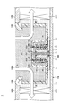
- FIG. 1 is a vertical sectional view showing an example of an indoor unit 1 of an air conditioner including an electric motor 400 according to the first embodiment.
- the indoor unit 1 of the air conditioner includes a housing 100, a heat exchanger 200, a turbofan 300, and an electric motor 400.
- the indoor unit 1 of the air conditioner is embedded in the ceiling inside the building, for example, in a state of being turned upside down from the state shown in FIG.
- the housing 100 accommodates a heat exchanger 200, a turbofan 300, an electric motor 400, and the like.
- the housing 100 includes a bottom plate portion 110, a top plate portion 120, and a bell mouth 130. Further, the top plate portion 120 is provided with an opening 120A for sucking air from the outside, and a bell mouth 130 is attached to the outer edge of the opening 120A.
- the heat exchanger 200 exchanges heat with the passing air by the action of the rotating turbofan 300, and cools or warms the air.
- the heat exchanger 200 is provided adjacent to the outer peripheral side of the turbofan 300 centered on the rotation axis AX and sandwiched between the bottom plate portion 110 and the top plate portion 120.
- the air sucked into the housing 100 from the opening 120A passes through the heat exchanger 200.
- a space hereinafter referred to as “low pressure space”) LP in which the air pressure is relatively low is formed upstream of the turbofan 300, and air is relatively downstream of the turbofan 300.
- a space with high pressure hereinafter referred to as "high pressure space” is formed.
- the turbofan 300 is attached to the rotor 10 of the electric motor 400, and is attached to a portion of the bottom plate portion 110 exposed from the opening 120A when the housing 100 is viewed as a single unit, via the electric motor 400.
- the turbofan 300 has a recess having a shape centered on the rotation axis AX and bulging toward the opening 120A, and the motor 400 is housed in this recess.
- the electric motor 400 rotates and drives the turbofan 300.
- the electric motor 400 is fixed to the portion of the bottom plate portion 110 exposed from the opening 120A when the housing 100 is viewed as a single unit, by fastening the fixing member 30 to the bottom plate portion 110 by bolts 34.
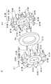
- FIG. 2 is a perspective view showing an outline of an example of the electric motor 400 according to the present embodiment.
- FIG. 3 is a perspective view showing an example of the configuration of the stator 20 according to the present embodiment. Specifically, FIG. 3 is a diagram in which the rotor 10 (rotor core 11, permanent magnet 12, and rotary shaft member 13) is not shown in FIG. 2.
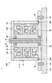
- FIG. 4 is an exploded view showing an example of the configuration of the stator unit 21 according to the present embodiment.
- FIG. 5 is an exploded view showing another example of the configuration of the stator unit 21 according to the present embodiment.
- the motor 400 is a so-called outer rotor type, and is driven by a multi-phase (three-phase in this example) armature current.
- the motor 400 includes a rotor 10, a stator 20, and a fixing member 30.
- the rotor 10 is arranged outside the radial direction (hereinafter, simply “diametrically”) of the motor 400 with respect to the stator 20, and the rotation axis AX. It is configured to be rotatable around.
- the rotor 10 includes a rotor core 11, a plurality of (20 in this example) permanent magnets 12, a rotating shaft member 13, and a connecting member 14.
- the rotor core (also referred to as “rotor core”) 11 has, for example, a substantially cylindrical shape, and is arranged so that the rotation axis AX of the motor 400 and the cylindrical axis substantially coincide with each other. Further, the rotor core 11 has substantially the same length as the stator 20 in the axial direction of the motor 400 (hereinafter, simply “axial direction”).
- the rotor core 11 is formed of, for example, a steel plate, cast iron, a dust core, or the like.
- the rotor core 11 is composed of, for example, one member in the axial direction. Further, as shown in FIG. 1, the rotor core 11 may be configured to include a plurality of (three in this example) rotor cores 11A to 11C stacked in the axial direction.
- a plurality of permanent magnets 12 (20 in this example) are arranged at equal intervals in the circumferential direction on the inner peripheral surface of the rotor core 11. Further, each of the plurality of permanent magnets 12 is formed so as to exist between substantially one end and substantially the other end of the rotor core 11 in the axial direction.
- the permanent magnet 12 is, for example, a neodymium sintered magnet or a ferrite magnet.
- Each of the plurality of permanent magnets 12 has different magnetic poles magnetized at both ends in the radial direction. Further, the two permanent magnets 12 adjacent to each other in the circumferential direction among the plurality of permanent magnets 12 have different magnetic poles magnetized inside in the radial direction facing the stator 20. Therefore, on the outside of the stator 20 in the radial direction, there are a permanent magnet 12 in which the N pole is magnetized inside in the radial direction and a permanent magnet 12 in which the S pole is magnetized inside in the radial direction. Are arranged alternately.
- Each of the plurality of permanent magnets 12 may be composed of one magnet member in the axial direction, or corresponds to the number of members of the plurality of (for example, stacked rotor cores 11) divided in the axial direction. It may be composed of three) magnet members. In this case, the same magnetic poles are all magnetized inside the plurality of magnet members constituting the permanent magnet 12 divided in the axial direction in the radial direction facing the stator 20.
- the plurality of permanent magnets 12 arranged in the circumferential direction include, for example, an annular ring magnet or a plastic magnet in which different magnetic poles are alternately magnetized in the circumferential direction, in the circumferential direction. It may be replaced with a permanent magnet composed of one member.
- the permanent magnet made of one member in the circumferential direction may be made of one member in the axial direction as well, and may be made of one member as a whole.
- the permanent magnet composed of one member in the circumferential direction may be divided into a plurality of members in the axial direction as in the case of the plurality of permanent magnets 12.
- the rotor core 11 may be omitted.
- the rotary shaft member 13 has, for example, a substantially cylindrical shape, and is arranged so that the rotary shaft center AX of the electric motor 400 and the columnar shaft center substantially coincide with each other.
- the rotary shaft member 13 is rotatably supported by, for example, bearings 25 and 32 (see FIG. 1 and the like) provided at both ends of the insertion member 24 in the axial direction.
- the insertion member 24 is fixed to the fixing member 30.
- the rotary shaft member 13 can rotate about the rotary shaft center AX with respect to the fixed member 30.
- the rotary shaft member 13 is, for example, an end portion (hereinafter, for convenience) opposite to the end portion on the fixing member 30 side of the motor 400 (hereinafter, “base end portion of the motor 400” for convenience) in the axial direction. It is connected to the rotor core 11 via the connecting member 14 at the "tip portion of the motor 400").
- the connecting member 14 may have, for example, a substantially disk shape that closes the open end of the substantially cylindrical shape of the rotor core 11.
- the rotor core 11 and the plurality of permanent magnets 12 fixed to the inner peripheral surfaces of the rotor core 11 match the rotation of the rotation shaft member 13 with respect to the rotation shaft core AX of the electric motor 400 with respect to the fixing member 30. Can rotate around.
- the connecting member 14 is fixed to the recess of the turbofan 300, that is, the back side opposite to the front side facing the opening 120A of the turbofan 300.
- the turbofan 300 can rotate with the rotation of the rotor 10.
- the turbofan 300 may be fixed to the outer side surface portion of the rotor core 11 in the radial direction instead of the connecting member 14 of the rotor 10. That is, the turbofan 300 may be fixed to the radial outer end of the rotor 10 instead of being fixed to one end in the axial direction of the rotor 10.
- the portion of the turbofan 300 facing the connecting member 14, that is, the portion corresponding to the bottom of the recess swelling toward the opening 120A in the turbofan 300 is omitted, and the connecting member 14 is viewed from the opening 120A. It may be a mode that is visibly exposed.
- stator 20 is arranged inside the rotor 10 (that is, the rotor core 11 and the permanent magnet 12) in the radial direction.
- the stator 20 includes a plurality of (three in this example) claw pole type stator units (hereinafter, simply “stator units”) 21, a plurality of (two in this example) interphase members 22, and an end.
- the portion member 23 and the insertion member 24 are included.
- the stator unit 21 includes a pair of stator cores 211 and winding 212.
- stator cores also referred to as "stator cores" 211 (an example of iron cores) are provided so as to surround the winding 212.
- the stator core 211 is formed of, for example, a steel plate, cast iron, a dust core, or the like.
- the stator core 211 includes a yoke portion 211A, a plurality of claw poles 211B, a yoke portion 211C, and an insertion hole 211D.
- the yoke portion 211A has an annular shape in the axial direction and has a predetermined thickness in the axial direction.
- the plurality of claw poles 211B are arranged at equal intervals in the circumferential direction on the outer peripheral surface of the yoke portion 211A, and each protrudes outward in the radial direction from the outer peripheral surface of the yoke portion 211A.
- the claw pole 211B includes the claw pole portion 211B1.
- the claw magnetic pole portion 211B1 has a predetermined width and protrudes from the outer peripheral surface of the yoke portion 211A by a predetermined length.
- the claw magnetic pole 211B further includes the claw magnetic pole portion 211B2.
- the claw magnetic pole portion 211B2 As a result, it is possible to secure a relatively wide facing area between the magnetic pole surface of the claw magnetic pole 211B magnetized by the armature current of the winding 212 and the rotor 10. Therefore, the torque of the electric motor 400 can be relatively increased, and the output of the electric motor 400 can be improved.
- the claw magnetic pole portion 211B2 protrudes from the tip of the claw magnetic pole portion 211B1 toward the other of the pair of stator cores 211 in an axial direction by a predetermined length.
- the claw magnetic pole portion 211B2 may have a constant width regardless of the distance from the claw magnetic pole portion 211B1.
- the claw magnetic pole portion 211B2 may have a tapered shape in which the width becomes narrower as the distance from the claw magnetic pole portion 211B1 in the axial direction increases.
- the claw magnetic pole portion 211B2 may be omitted.
- the yoke portion 211C is configured such that a portion near the inner peripheral surface of the yoke portion 211A projects by a predetermined amount toward the other of the pair of stator cores 211.
- the outer diameter of the yoke portion 211C is larger than that of the yoke portion 211A in the axial direction. It has a small ring shape.
- the pair of stator cores 211 come into contact with each other at the yoke portions 211C, and a space for accommodating the winding 212 is generated between the pair of yoke portions 211A corresponding to the pair of stator cores 211.
- the insertion member 24 is inserted into the insertion hole 211D.
- the insertion hole 211D is realized by the inner peripheral surfaces of the yoke portion 211A and the yoke portion 211C.
- the winding (also referred to as "coil") 212 is wound in an annular shape in the axial direction. One end of the winding 212 is electrically connected to the external terminal, and the other end is electrically connected to the neutral point or the external terminal.
- the winding 212 is arranged between the pair of stator cores 211 (yoke portion 211A) in the axial direction. Further, the winding 212 is wound so that the inner peripheral portion is radially outside the yoke portion 211C of the pair of stator cores 211.
- the claw poles 211B of one stator core 211 and the claw poles 211B of the other stator core 211 are alternately arranged in the circumferential direction. Can be combined with. Further, when an armature current flows through the annular winding 212, the claw magnetic pole 211B formed on one of the pair of stator cores 211 and the claw magnetic pole 211B formed on the other are magnetized to different magnetic poles. Will be done.
- one claw pole 211B protruding from one stator core 211 is adjacent in the circumferential direction, and is different from the other claw poles 211B protruding from the other stator core 211.
- the N-pole claw poles 211B and the S-pole claw poles 211B are alternately arranged in the circumferential direction of the pair of stator cores 211.
- stator units 21 are stacked in the axial direction.
- the plurality of stator units 21 include stator units 21 for a plurality of phases (three phases in this example). Specifically, the plurality of stator units 21 include a stator unit 21A corresponding to the U phase, a stator unit 21B corresponding to the V phase, and a stator unit 21C corresponding to the W phase. The plurality of stator units 21 are laminated in the order of the stator unit 21A corresponding to the U phase, the stator unit 21B corresponding to the V phase, and the stator unit 21C corresponding to the W phase from the tip of the motor 400. To. The stator units 21A to 21C are arranged so that their positions in the circumferential direction differ from each other by 120 ° in terms of electrical angle.
- the electric machine 400 may be driven by an armature current of two phases or less, or may be driven by an armature current of four or more phases.
- the interphase member 22 is provided between the stator units 21 of different phases adjacent in the axial direction.
- the interphase member 22 is, for example, a non-magnetic material. As a result, a predetermined distance can be secured between the two stator units 21 of different phases, and magnetic flux leakage between the two stator units 21 of different phases can be suppressed.
- the interphase member 22 includes a UV interphase member 22A and a VW interphase member 22B.
- the UV-phase member 22A is provided between the U-phase stator unit 21A and the V-phase stator unit 21B, which are adjacent in the axial direction.
- the UV interphase member 22A has, for example, a substantially cylindrical shape (substantially disk shape) having a predetermined thickness, and an insertion hole through which the insertion member 24 is inserted is formed in the central portion.
- the same may apply to the VW interphase member 22B.
- the VW interphase member 22B is provided between the V-phase stator unit 21B and the W-phase stator unit 21C, which are adjacent in the axial direction.
- the end member 23 is provided at the end on the tip end side of the motor 400 of the plurality of stator units 21 to be laminated. Specifically, the end member 23 is provided so as to be in contact with the end surface of the stator unit 21A on the side opposite to the side facing the stator unit 21B in the axial direction.
- the end member 23 has, for example, a substantially cylindrical shape (substantially disk shape) having a predetermined thickness, and an insertion hole through which the insertion member 24 is inserted is formed in the central portion.
- the end member 23 is, for example, a non-magnetic material. As a result, magnetic flux leakage from the stator unit 21A (specifically, the stator core 211 on the tip end side of the motor 400) can be suppressed.
- the insertion member 24 has the tip end member 23, the stator unit 21A, the UV interphase member 22A, the stator unit 21B, the VW interphase member 22B, and the stator unit 21C inserted in this order from the tip end side of the motor 400.
- the portion is fixed to the fixing member 30.
- the insertion member 24 has, for example, a male screw portion at the tip end portion, and is fixed to the fixing member 30 by being fastened to the corresponding female screw portion of the fixing member 30.
- the insertion member 24 has, for example, a substantially cylindrical shape, and the rotary shaft member 13 is rotatably arranged in the hole portion realized by the inner peripheral surface.
- a bearing 25 is provided at the tip of the insertion member 24 to rotatably support the rotary shaft member 13 on the tip side of the motor 400.
- the insertion member 24 has a head having an outer diameter relatively larger than the inner diameter of the insertion hole 211D of the stator unit 21 on the tip end side of the electric motor 400.
- a force in the axial direction toward the fixing member 30 can be applied to the end member 23 from the head. Therefore, the plurality of stator units 21 (stator units 21A to 21C) and the interphase member 22 (UV interphase member 22A, VW interphase member 22B) are fixed to the fixing member 30 by being sandwiched between the end member 23 and the fixing member 30. be able to.
- stator units 21A to 21C can be fixed to the stator units 21A to 21C in a form in which compressive stress acts on the stator core 211.
- the dust core has a relatively low strength against tensile stress, while a relatively high strength against compressive stress. Therefore, even when the stator core 211 is formed of a dust core, the stator units 21A to 21C can be fixed by a method more appropriate in terms of strength.
- the fixing member 30 is fastened to the bottom plate portion 110 by a plurality of bolts 34 as described above.
- the electric motor 400 is fixed to the bottom plate portion 110.
- the fixing member 30 has a predetermined distance from the bottom plate portion 110, and a vibration-proof member (for example, vibration-proof rubber) is interposed between the fixing member 30 and the bottom plate portion 110.
- the anti-vibration member may be fastened together with the fixing member 30 by, for example, bolts 34.
- the fixing member 30 (an example of a support member) has, for example, a substantially disk shape having an outer diameter larger than that of the rotor 10 (rotor core 11) in the axial direction, and has a predetermined thickness in the axial direction. As described above, the rotor 10 is rotatably supported on the fixing member 30 via the insertion member 24, and the stator 20 is fixed.
- the fixing member 30 is provided with a bearing 32 that rotatably supports the rotary shaft member 13 on the proximal end side of the motor 400.
- FIG. 6 is a perspective view of a vertical cross section showing the internal structure of an example of the electric motor 400 according to the present embodiment.
- a through hole 14A (hole) penetrating between the inner space in which the stator 20 is arranged and the outer space in which the turbofan 300 is fixed is formed.
- An example of the part) is provided.
- the number of through holes 14A may be one or a plurality. In this example (FIG. 1), a plurality of through holes 14A are provided in the circumferential direction centered on the rotation axis AX of the connecting member 14.
- the through hole 14A is such that at least a part of the through hole 14A overlaps with the portion of the stator core 211 located at the end on the tip end side of the motor 400 where the claw pole 211B (claw pole portion 211B1) is not provided. It will be provided.
- the turbofan 300 is provided with a through hole 302 penetrating between a portion on the front surface side that is visibly exposed from the opening 120A and a portion on the back surface side to which the connecting member 14 of the motor 400 is attached.
- the through hole 302 is provided so as to communicate with the through hole 14A.
- the turbofan 300 when the turbofan 300 is fixed to the radial outer surface of the rotor 10 and one end of the rotor 10 is not covered by the turbofan 300 and is exposed to the low pressure space LP, a through hole is formed.
- the 14A can communicate with the low pressure space LP without passing through the through hole 302.
- the pair of stator cores 211 of the stator unit 21 are combined so that the claw magnetic pole portions 211B2 are alternately arranged in the circumferential direction, and the adjacent claws are adjacent to each other.
- a predetermined gap is provided between the magnetic pole portions 211B2. Therefore, the space outside the stator unit 21 (stator core 211) in the radial direction and the space containing the winding 212 inside the stator core 211 (hereinafter, "inside the stator unit 21" for convenience. It communicates with the space ”) in a movable manner.
- the pair of stator cores 211 of the stator unit 21 are combined so that the claw magnetic poles 211B (claw magnetic pole portions 211B1) are alternately arranged in the circumferential direction in the axial direction. Therefore, by appropriately setting the shape of the end member 23 in the axial direction, the outer space of the stator unit 21 in the axial direction and the inner space of the stator units 21A and 21C located at the end in the axial direction are formed. The air communicates with the space in a movable manner.
- the end member 23 is arranged so that a portion of the stator core 211 adjacent to the stator core 211 where the claw magnetic pole 211B (claw magnetic pole portion 211B1) is not provided has an overlapping region in the axial direction.
- the UV interphase member 22A and the VW interphase member 22B each have a penetrating portion straddling a portion of the two adjacent stator cores 211 where the claw poles 211B (claw poles 211B1) are not provided. May have.
- the winding 212 provided inside the stator unit 21 can be cooled. Therefore, the cooling efficiency of the electric motor 400 can be improved. Further, when sufficient cooling efficiency can be obtained, it is not necessary to provide an additional cooling structure such as a heat sink, and even if sufficient cooling efficiency cannot be obtained, an additional cooling structure such as a heat sink can be used. Recruitment can be limited to a minimum. Therefore, it is possible to suppress the increase in size of the electric motor 400.
- FIGS. 2 to 5 will be referred to, and the description will be made focusing on the parts different from the first embodiment. Therefore, the description of the same or corresponding configuration as in the first embodiment may be simplified or omitted.
- FIG. 7 is a vertical sectional view schematically showing an example of an indoor unit 1 of an air conditioner including the motor 400 according to the second embodiment.
- FIG. 7 is drawn centering on the configuration near the motor 400, and shows the top plate portion 120, the bell mouth 130, the heat exchanger 200, the turbofan 300, and the like in the configuration of the indoor unit 1 of the air conditioner. Is omitted.
- the fixing member 30 is provided with the groove portion 30A.
- the groove portion 30A is a part or all of the circumferential direction centered on the rotating shaft center AX so as to include all the positions where the rotor core 11 and the permanent magnet 12 are arranged in the radial direction centered on the rotating shaft center AX. It is provided over.
- the gap 36 between the other end of the rotor 10 (rotor core 11 and the permanent magnet 12) opposite to the one end in the axial direction fixed to the connecting member 14 and the fixing member 30 is relatively wide. Can be made larger. Therefore, when the motor 400 is operating, the flow rate of the air (see the dotted arrow in the figure) flowing into the space inside the rotor 10 through the gap 36 can be relatively increased. Therefore, the cooling efficiency of the electric motor 400 can be further improved.
- FIGS. 2 to 5 will be referred to, and the description will be made focusing on the parts different from the first embodiment. Therefore, the description of the same or corresponding configuration as in the first embodiment may be simplified or omitted.
- FIG. 8 is a vertical sectional view showing an example of an indoor unit 1 of an air conditioner including an electric motor 400 according to a third embodiment.
- the configuration of the indoor unit 1 of the air conditioner other than the motor 400 may be the same as that of the first embodiment and the like. .. Therefore, the description thereof will be omitted.
- the fixing member 30 is provided with a through hole 38.
- the through hole 38 is arranged at a position where the stator unit 21C is provided in the radial direction about the rotation axis AX. Further, in the through hole 38, at least a part of the stator core 211 in which the opening on the stator unit 21C side is not provided with the claw pole 211B (claw pole portion 211B1) of the stator core 211 in the axial direction is at least a part. It is provided to include. As a result, the through hole 38 is in such a manner that air can move between the space inside the stator unit 21C and the space between the bottom plate portion 110 on the back side of the fixing member 30, that is, the high pressure space HP. Can be communicated. Therefore, as shown in FIG.
- the air in the high-voltage space HP flows into the space inside the rotor 10 through the through hole 38 in addition to the gap 36. Then, the inflowing air extends over the plurality of stator units 21, passes through the space inside each stator unit 21 in the axial direction, and flows out to the low pressure space LP through the through hole 14A and the through hole 302. Therefore, the flow rate of the air introduced into the space inside the rotor 10 can be increased, and the cooling efficiency of the motor 400 can be further improved.
- the air flowing into the space inside the rotor 10 flows in the axial direction from the through hole 38 with respect to the stator unit 21C located at the base end portion of the motor 400. Therefore, air easily hits the winding 212 of the stator unit 21C, the cooling efficiency of the stator unit 21C can be improved, and the cooling efficiency of the motor 400 as a whole can be further improved.
- FIGS. 2 to 5 will be referred to, and the description will be made focusing on the parts different from the first embodiment. Therefore, the description of the same or corresponding configuration as in the first embodiment may be simplified or omitted.
- FIG. 9 is a cross-sectional view showing an example of the electric motor 400 according to the fourth embodiment.
- the winding 212 is drawn with a dotted line in order to make the through hole 211E easy to see.
- the configuration of the indoor unit 1 of the air conditioner other than the motor 400 may be the same as that of the first embodiment and the like. .. Therefore, the illustration of the indoor unit 1 of the air conditioner including the motor 400 according to the fourth embodiment is omitted.
- the through hole 211E is provided in the claw magnetic pole portion 211B1.
- the through hole 211E penetrates the claw magnetic pole portion 211B1 in the axial direction. Further, the through hole 211E is provided so as to overlap at least a part of the radial position where the winding 212 is arranged in the axial direction. Thereby, for example, the air introduced into the space inside the rotor 10 through the gap 36 can flow inside the stator unit 21 while passing through the through hole 211E. Therefore, air can be directly applied to the winding 212 through the through hole 211E. Therefore, the cooling efficiency of the electric motor 400 can be further improved.
- the through hole 211E is provided so as to extend in the radial direction in the axial direction, and the circumferential length of the opening is relatively longer than the radial length.
- the cross-sectional area of the through hole 211E occupying the claw magnetic pole portion 211B1 can be made relatively small in the radial direction. Therefore, in the stator core 211, it is possible to improve the cooling efficiency of the motor 400 while suppressing the influence of the through hole 211E on the flow of the magnetic flux MF flowing in the radial direction.
- FIGS. 2 to 5 will be referred to, and the description will be made focusing on the parts different from the first embodiment. Therefore, the description of the same or corresponding configuration as in the first embodiment may be simplified or omitted.
- FIG. 10 is a cross-sectional view showing an example of the electric motor 400 according to the fifth embodiment.
- the configuration of the indoor unit 1 of the air conditioner other than the motor 400 may be the same as that of the first embodiment and the like. .. Therefore, the illustration of the indoor unit 1 of the air conditioner including the motor 400 according to the fifth embodiment is omitted.
- the spacer 40 is in contact with the pawl magnetic pole portions 211B2 adjacent to each other in the circumferential direction of the stator unit 21 (a pair of stator cores 211) over the entire circumference. It is provided in contact with each other.
- the spacer 40 (an example of a resistance member) is, for example, a non-magnetic material, and is used for positioning between a pair of stator cores in the stator unit 21.
- the spacer 40 is, for example, an annular inner peripheral portion that abuts on the radial inner surface of the claw magnetic pole portion 211B2 and the axial inner surface of the claw magnetic pole portion 211B1 and a claw magnetic pole that is adjacent to the claw magnetic pole portion in the circumferential direction. Includes an outer peripheral portion protruding into the space between portions 211B2. As a result, the flow path resistance at the outer end of the space inside the stator unit 21 becomes relatively large.
- the air introduced into the space inside the rotor 10 through the gap 36 passes through the space inside the rotor 10 in the radial direction (for example, the range surrounded by the dotted line in FIG. 10) of the stator unit 21. It flows inside. Therefore, inside the stator unit 21, air easily hits the windings 212 arranged relatively inward in the radial direction, and the cooling efficiency of the motor 400 can be further improved.
- At least two of the groove portion 30A of the second embodiment, the through hole 38 of the third embodiment, the through hole 211E of the fourth embodiment, and the spacer 40 of the fifth embodiment are of the first embodiment. It may be appropriately combined with the motor 400.
- FIGS. 2 to 5 will be referred to, and the description will be made focusing on the parts different from the first embodiment. Therefore, the description of the same or corresponding configuration as in the first embodiment may be simplified or omitted.
- the groove portion 30A provided in the fixing member 30 of the second embodiment described above may be used for a different purpose other than the use for improving the cooling efficiency of the motor 400.
- a method of using the groove portion 30A will be described.
- FIG. 11 is a vertical sectional view showing an example of the electric motor 400 according to another embodiment.
- the configuration of the indoor unit 1 of the air conditioner other than the motor 400 may be the same as that of the first embodiment. Therefore, in FIG. 11, the configuration near the motor 400 is drawn mainly, and the top plate portion 120, the bell mouth 130, the heat exchanger 200, the turbofan 300, and the like in the configuration of the indoor unit 1 of the air conditioner are shown. Is omitted.
- FIG. 12 which will be described later.
- the fixing member 30 is provided with the groove portion 30A as in the case of the second embodiment.
- the axial lengths of the rotor 10, that is, the rotor core 11 and the permanent magnet 12 are longer than in the case of the second embodiment described above, and the rotor core 11 is axially longer. And the tip of the permanent magnet 12 has entered the groove 30A. Thereby, the amount of the permanent magnet 12 can be relatively increased.
- the extension amount of the axial lengths of the rotor core 11 and the permanent magnet 12 with respect to the case where the groove portion 30A is not provided is about the same as the depth of the groove portion 30A. It may be smaller than the depth of the groove 30A.
- the amount of the permanent magnet 12 can be prioritized and the amount of the permanent magnet 12 can be maximized. Further, in the latter case, the amount of the permanent magnets 12 can be relatively increased, and the cooling efficiency of the electric motor 400 can be further improved.
- FIG. 12 is a vertical sectional view showing an example of the electric motor 400 according to another embodiment.
- the fixing member 30 is provided with the groove portion 30A as in the case of the second embodiment.
- the rotor 10 is moved to the fixing member 30 side in the axial direction, and the tip portions of the rotor core 11 and the permanent magnet 12 are placed in the groove portion 30A. It's getting in.
- the axial length of the electric motor 400 can be relatively shortened as compared with the case of the second embodiment described above (the length L1 of the electric motor 400 of the second embodiment in FIG. 12).
- the length L2 of the motor 400 of this example can be relatively shortened as compared with the case of the second embodiment described above.
- the amount of shortening of the axial length of the electric motor 400 when the groove portion 30A is not provided may be about the same as the depth of the groove portion 30A, or the groove portion 30A may be shortened. It may be smaller than the depth.
- priority is given to miniaturization of the motor 400 in the axial direction, and the length of the motor 400 can be shortened to the maximum. Further, in the latter case, the size of the electric motor 400 in the axial direction can be reduced, and the cooling efficiency of the electric motor 400 can be further improved.
- the axial length of the stator 20 is the same as in the case of the first embodiment described above as long as an axial gap between the connecting member 14 of the rotor 10 and the stator 20 can be secured. May be maintained. Further, the axial length of the stator 20 may be shortened as the rotor 10 is moved toward the fixing member 30 in the axial direction.
- the electric motor 400 includes a rotor 10 and a stator 20.
- the rotor 10 is rotatably configured around the rotation axis AX, and the turbofan 300 is fixed.
- the stator 20 is arranged inside the rotor 10 and has a winding 212 that is wound in an annular shape around the rotation axis AX and a stator core 211 that is provided so as to surround the winding 212.
- a through hole 14A penetrating between the inside where the stator 20 is provided and the outside where the turbofan 300 is provided is provided.
- an inflow path capable of allowing the surrounding fluid (air) to flow into the inside of the stator unit 21C provided at the other end on the opposite side of the motor 400 (that is, the surface of the winding 212) is provided.
- the air of the high pressure space HP can flow into the inside of the stator unit 21C provided at the other end through the inflow path, and the fluid can flow out to the low pressure space LP through the through hole 14A at the end. Therefore, an air flow can be created inside the stator unit 21 provided with the winding 212 from the other end to one end of the stator 20 inside the rotor 10 to cool the winding 212. .. Therefore, the cooling performance of the motor 400 can be improved. For example, it is not necessary to provide a heat sink or the like for cooling the motor 400, or even if it is necessary to provide a heat sink or the like, the size can be minimized. , It is possible to suppress the increase in size of the electric motor 400.
- the electric motor 400 may rotationally drive a fluid driving means other than the turbofan 300. Further, the motor 400 may rotate drive a fluid driving means for driving a fluid other than air. In this case as well, the same action / effect is obtained.
- the turbofan 300 has a through hole 302 penetrating between the front surface side exposed to the low pressure space LP and the back surface side fixed to the stator 20. May be prepared.
- the through hole 14A of the rotor 10 (connecting member 14) may communicate with the through hole 302.
- the fixing member 30 supports the stator 20 at the other end portion in the axial direction (that is, the base end portion of the motor 400).
- the inflow path through which the surrounding fluid can flow into the stator unit 21 may include a gap 36 between the rotor 10 and the fixing member 30.
- the fixing member 30 supports the stator 20 at the other end portion in the axial direction (base end portion of the motor 400).
- the inflow path through which the surrounding fluid can flow into the stator unit 21 includes a through hole 38 provided in the fixing member 30.
- the air of the high-pressure space HP is introduced from the through hole 38, the air is allowed to flow inside the stator unit 21, and the air is made to flow out from the through hole 14A to the low-pressure space LP. Can be done. Further, the air introduced into the space inside the rotor 10 flows into the stator unit 21 at the base end of the motor 400 in the axial direction from the through hole 38. Therefore, air easily hits the winding 212 of the stator unit 21C, and the cooling efficiency of the motor 400 can be further improved.
- the stator core 211 has a through hole 211E penetrating in the axial direction, which is provided so as to overlap at least a part of the winding 212 in the axial direction.
- the air introduced into the stator unit 21 through the inflow path can move in the axial direction while passing through the through hole 211E. Therefore, air can be directly applied to the winding 212 through the through hole 211E. Therefore, the cooling efficiency of the electric motor 400 can be further improved.
- the through hole 211E of the stator core 211 is provided so that the opening extends substantially in the radial direction, and the circumferential length of the opening is the radial length.
- it may be provided so as to be relatively small.
- the cross-sectional area of the through hole 211E occupying the stator core 211 (claw magnetic pole portion 211B1) can be made relatively small in the radial direction. Therefore, in the stator core 211 of the stator 20 (stator unit 21), it is possible to suppress the influence of the through hole 211E on the flow of the magnetic flux flowing in the radial direction.
- a spacer 40 is provided which relatively increases the flow path resistance at the outer end portion in the radial direction of the stator 20.
- the motor 400 according to the above-described embodiment may be applied to the outdoor unit of the air conditioner instead of or in addition to the indoor unit 1 of the air conditioner.
Abstract
Provided is a technique making it possible to suppress an increase in size of an electric motor. An electric motor 400 according to an embodiment of the present disclosure comprises: a rotor 10 that is configured to be rotatable around a rotation axis AX and has a turbo fan 300 fixed thereto; a stator 20 having a claw pole type stator unit 21 that includes a winding 212 arranged inside the rotor 10 and wound annularly around the rotation axis AX and a stator core 211 provided so as to surround the winding 212; a through hole 14A that is provided at one end of the rotor 10 and passes through between the inside where the stator 20 is provided and the outside where the turbo fan 300 is fixed; and an inflow path (for example, a gap 36, a through hole 38, etc.) into which surrounding fluid can be caused to flow inside a stator unit 21C provided at the other end on the opposite side of the one end in the axial direction.
Description
本開示は、電動機に関する。
This disclosure relates to motors.
例えば、ファン等の流体駆動手段を駆動する電動機にヒートシンクが設けられる場合がある(特許文献1参照)。
For example, a heat sink may be provided in an electric motor that drives a fluid driving means such as a fan (see Patent Document 1).
しかしながら、電動機にヒートシンクが設けられると、電動機が大型化する可能性がある。
However, if a heat sink is provided on the motor, the motor may become larger.
本開示は、電動機の大型化を抑制することが可能な技術を提供することを目的とする。
The purpose of this disclosure is to provide a technology capable of suppressing the increase in size of a motor.
本開示に係る一実施形態では、
回転軸心回りに回転自在に構成され、流体駆動手段が固定される回転子と、
前記回転子の内側に配置され、回転軸心回りに環状に巻回される巻線と、前記巻線の周囲を包囲するように設けられる鉄心とを含む、クローポール型の固定子ユニットを有する固定子と、
前記回転子の一端部に設けられ、前記固定子が設けられる内側と前記流体駆動手段が固定される外側との間を貫通する孔部と、
軸方向で前記一端部の反対側の他端部に設けられる前記固定子ユニットの内側に、周囲の流体を流入させることが可能な流入路と、を備える、
電動機が提供される。 In one embodiment of the present disclosure,
A rotor that is rotatably configured around the center of rotation and to which the fluid driving means is fixed,
It has a claw pole type stator unit that includes a winding that is arranged inside the rotor and is wound in an annular shape around the center of rotation, and an iron core that is provided so as to surround the winding. With a stator,
A hole provided at one end of the rotor and penetrating between the inside where the stator is provided and the outside where the fluid driving means is fixed.
Inside the stator unit provided at the other end on the opposite side of the one end in the axial direction, an inflow path capable of allowing the surrounding fluid to flow in is provided.
A motor is provided.
本実施形態によれば、流入路を通じて、他端部に設けられる固定子ユニットの内側に空気を流入させ、一端部の孔部を通じて、流体を流出させることができる。そのため、回転子の内側の固定子の他端部から一端部に亘って、巻線が設けられる固定子ユニットの内側に空気の流れを作り出し、巻線を冷却することができる。よって、例えば、電動機の冷却用のヒートシンク等を設ける必要がなくなったり、ヒートシンク等を設ける必要があっても、最小限のサイズにしたりすることで、電動機の大型化を抑制することができる。
According to the present embodiment, air can flow into the inside of the stator unit provided at the other end through the inflow path, and the fluid can flow out through the hole at one end. Therefore, an air flow can be created inside the stator unit provided with the winding from the other end to one end of the stator inside the rotor, and the winding can be cooled. Therefore, for example, it is not necessary to provide a heat sink or the like for cooling the electric motor, or even if it is necessary to provide a heat sink or the like, the size of the electric motor can be suppressed to the minimum size.
また、上述の実施形態において、
前記流体駆動手段は、表面側と前記固定子に固定される裏面側との間を貫通する貫通孔を備え、
前記孔部は、前記貫通孔に連通していてもよい。 Further, in the above-described embodiment,
The fluid driving means includes a through hole penetrating between the front surface side and the back surface side fixed to the stator.
The hole may communicate with the through hole.
前記流体駆動手段は、表面側と前記固定子に固定される裏面側との間を貫通する貫通孔を備え、
前記孔部は、前記貫通孔に連通していてもよい。 Further, in the above-described embodiment,
The fluid driving means includes a through hole penetrating between the front surface side and the back surface side fixed to the stator.
The hole may communicate with the through hole.
また、上述の実施形態において、
軸方向の前記他端部で前記固定子を支持する支持部材を備え、
前記流入路は、前記回転子と前記支持部材との間の隙間を含んでもよい。 Further, in the above-described embodiment,
A support member for supporting the stator at the other end in the axial direction is provided.
The inflow path may include a gap between the rotor and the support member.
軸方向の前記他端部で前記固定子を支持する支持部材を備え、
前記流入路は、前記回転子と前記支持部材との間の隙間を含んでもよい。 Further, in the above-described embodiment,
A support member for supporting the stator at the other end in the axial direction is provided.
The inflow path may include a gap between the rotor and the support member.
また、上述の実施形態において、
軸方向の前記他端部で前記固定子を支持する支持部材を備え、
前記流入路は、前記支持部材に設けられる貫通孔を含んでもよい。 Further, in the above-described embodiment,
A support member for supporting the stator at the other end in the axial direction is provided.
The inflow path may include a through hole provided in the support member.
軸方向の前記他端部で前記固定子を支持する支持部材を備え、
前記流入路は、前記支持部材に設けられる貫通孔を含んでもよい。 Further, in the above-described embodiment,
A support member for supporting the stator at the other end in the axial direction is provided.
The inflow path may include a through hole provided in the support member.
また、上述の実施形態において、
前記鉄心は、軸方向から見て、前記巻線と少なくとも一部が重複するように設けられる、軸方向に貫通する貫通孔を有してもよい。 Further, in the above-described embodiment,
The iron core may have a through hole penetrating in the axial direction, which is provided so as to overlap at least a part of the winding when viewed from the axial direction.
前記鉄心は、軸方向から見て、前記巻線と少なくとも一部が重複するように設けられる、軸方向に貫通する貫通孔を有してもよい。 Further, in the above-described embodiment,
The iron core may have a through hole penetrating in the axial direction, which is provided so as to overlap at least a part of the winding when viewed from the axial direction.
また、上述の実施形態において、
前記鉄心の貫通孔は、開口が略径方向に延びるように設けられ、且つ、前記開口の周方向の長さが、径方向の長さに対して、相対的に小さくなるように設けられてもよい。 Further, in the above-described embodiment,
The through hole of the iron core is provided so that the opening extends substantially in the radial direction, and the length in the circumferential direction of the opening is provided so as to be relatively smaller than the length in the radial direction. May be good.
また、上述の実施形態において、
前記固定子の径方向の外端部の流路抵抗を相対的に大きくする抵抗部材を備えてもよい。 Further, in the above-described embodiment,
A resistance member may be provided that relatively increases the flow path resistance at the radial outer end of the stator.
前記固定子の径方向の外端部の流路抵抗を相対的に大きくする抵抗部材を備えてもよい。 Further, in the above-described embodiment,
A resistance member may be provided that relatively increases the flow path resistance at the radial outer end of the stator.
上述の実施形態によれば、電動機の大型化を抑制することが可能な技術を提供することができる。
According to the above-described embodiment, it is possible to provide a technique capable of suppressing the increase in size of the electric motor.
以下、図面を参照して実施形態について説明する。
Hereinafter, embodiments will be described with reference to the drawings.
[第1実施形態]
第1実施形態について説明する。 [First Embodiment]
The first embodiment will be described.
第1実施形態について説明する。 [First Embodiment]
The first embodiment will be described.
<空気調和機の室内ユニットの概要>
まず、図1を参照して、第1実施形態に係る電動機400を含む空気調和機の室内ユニット1について説明する。 <Overview of the indoor unit of the air conditioner>
First, theindoor unit 1 of the air conditioner including the motor 400 according to the first embodiment will be described with reference to FIG.
まず、図1を参照して、第1実施形態に係る電動機400を含む空気調和機の室内ユニット1について説明する。 <Overview of the indoor unit of the air conditioner>
First, the
図1は、第1実施形態に係る電動機400を含む空気調和機の室内ユニット1の一例を示す縦断面図である。
FIG. 1 is a vertical sectional view showing an example of an indoor unit 1 of an air conditioner including an electric motor 400 according to the first embodiment.
図1に示すように、空気調和機の室内ユニット1は、筐体100と、熱交換器200と、ターボファン300と、電動機400とを含む。空気調和機の室内ユニット1は、例えば、図1の状態から上下逆転された状態で、建物の室内の天井に埋設される。
As shown in FIG. 1, the indoor unit 1 of the air conditioner includes a housing 100, a heat exchanger 200, a turbofan 300, and an electric motor 400. The indoor unit 1 of the air conditioner is embedded in the ceiling inside the building, for example, in a state of being turned upside down from the state shown in FIG.
筐体100は、熱交換器200、ターボファン300、及び電動機400等を収容する。筐体100は、底板部110と、天板部120と、ベルマウス130とを含む。また、天板部120には、外部から空気を吸入するための開口部120Aが設けられ、開口部120Aの外縁にベルマウス130が取り付けられる。
The housing 100 accommodates a heat exchanger 200, a turbofan 300, an electric motor 400, and the like. The housing 100 includes a bottom plate portion 110, a top plate portion 120, and a bell mouth 130. Further, the top plate portion 120 is provided with an opening 120A for sucking air from the outside, and a bell mouth 130 is attached to the outer edge of the opening 120A.
熱交換器200は、回転するターボファン300の作用により通過する空気と熱交換を行い、空気を冷やしたり、暖めたりする。熱交換器200は、回転軸心AXを中心とするターボファン300の外周側に隣接して、底板部110及び天板部120の間に挟持される形で設けられる。
The heat exchanger 200 exchanges heat with the passing air by the action of the rotating turbofan 300, and cools or warms the air. The heat exchanger 200 is provided adjacent to the outer peripheral side of the turbofan 300 centered on the rotation axis AX and sandwiched between the bottom plate portion 110 and the top plate portion 120.
ターボファン300(流体駆動手段の一例)は、開口部120Aから筐体100の内部に吸入した空気は熱交換器200を通過する。ターボファン300が回転駆動されることにより、ターボファン300の上流に相対的に空気の圧力が低い空間(以下、「低圧空間」)LPが形成され、ターボファン300の下流に相対的に空気の圧力が高い空間(以下、「高圧空間」)が形成される。ターボファン300は、電動機400の回転子10に取り付けられ、電動機400を介して、底板部110における筐体100単体で見たときに開口部120Aから露出する部分に取り付けられる。ターボファン300は、回転軸心AXを中心とする、開口部120A側に膨らむ形の凹部を有し、この凹部に電動機400が収容される。
In the turbofan 300 (an example of a fluid driving means), the air sucked into the housing 100 from the opening 120A passes through the heat exchanger 200. By rotationally driving the turbofan 300, a space (hereinafter referred to as “low pressure space”) LP in which the air pressure is relatively low is formed upstream of the turbofan 300, and air is relatively downstream of the turbofan 300. A space with high pressure (hereinafter referred to as "high pressure space") is formed. The turbofan 300 is attached to the rotor 10 of the electric motor 400, and is attached to a portion of the bottom plate portion 110 exposed from the opening 120A when the housing 100 is viewed as a single unit, via the electric motor 400. The turbofan 300 has a recess having a shape centered on the rotation axis AX and bulging toward the opening 120A, and the motor 400 is housed in this recess.
電動機400は、ターボファン300を回転駆動する。電動機400は、固定部材30がボルト34により底板部110に締結されることにより、底板部110における筐体100単体で見たときに開口部120Aから露出する部分に固定される。
The electric motor 400 rotates and drives the turbofan 300. The electric motor 400 is fixed to the portion of the bottom plate portion 110 exposed from the opening 120A when the housing 100 is viewed as a single unit, by fastening the fixing member 30 to the bottom plate portion 110 by bolts 34.
<電動機の基本構成>
次に、図1に加えて、図2~図5を参照して、本実施形態に係る電動機400の基本構成について説明する。 <Basic configuration of motor>
Next, in addition to FIG. 1, the basic configuration of theelectric motor 400 according to the present embodiment will be described with reference to FIGS. 2 to 5.
次に、図1に加えて、図2~図5を参照して、本実施形態に係る電動機400の基本構成について説明する。 <Basic configuration of motor>
Next, in addition to FIG. 1, the basic configuration of the
図2は、本実施形態に係る電動機400の一例の概要を示す斜視図である。図3は、本実施形態に係る固定子20の構成の一例を示す斜視図である。具体的には、図3は、図2において、回転子10(回転子鉄心11、永久磁石12、及び回転軸部材13)の図示を省略した図である。図4は、本実施形態に係る固定子ユニット21の構成の一例を示す分解図である。図5は、本実施形態に係る固定子ユニット21の構成の他の例を示す分解図である。
FIG. 2 is a perspective view showing an outline of an example of the electric motor 400 according to the present embodiment. FIG. 3 is a perspective view showing an example of the configuration of the stator 20 according to the present embodiment. Specifically, FIG. 3 is a diagram in which the rotor 10 (rotor core 11, permanent magnet 12, and rotary shaft member 13) is not shown in FIG. 2. FIG. 4 is an exploded view showing an example of the configuration of the stator unit 21 according to the present embodiment. FIG. 5 is an exploded view showing another example of the configuration of the stator unit 21 according to the present embodiment.
尚、図2では、図1に示す連結部材14の図示が省略されている。
Note that, in FIG. 2, the illustration of the connecting member 14 shown in FIG. 1 is omitted.
図1、図2に示すように、電動機400は、いわゆるアウタロータ型であり、複数相(本例では、3相)の電機子電流で駆動される。
As shown in FIGS. 1 and 2, the motor 400 is a so-called outer rotor type, and is driven by a multi-phase (three-phase in this example) armature current.
電動機400は、回転子10と、固定子20と、固定部材30とを含む。
The motor 400 includes a rotor 10, a stator 20, and a fixing member 30.
図2に示すように、回転子(「ロータ」とも称する)10は、固定子20に対して、電動機400の径方向(以下、単に「径方向」)の外側に配置され、回転軸心AXまわりに回転可能に構成される。回転子10は、回転子鉄心11と、複数(本例では、20個)の永久磁石12と、回転軸部材13と、連結部材14とを含む。
As shown in FIG. 2, the rotor (also referred to as “rotor”) 10 is arranged outside the radial direction (hereinafter, simply “diametrically”) of the motor 400 with respect to the stator 20, and the rotation axis AX. It is configured to be rotatable around. The rotor 10 includes a rotor core 11, a plurality of (20 in this example) permanent magnets 12, a rotating shaft member 13, and a connecting member 14.
回転子鉄心(「ロータコア」とも称する)11は、例えば、略円筒形状を有し、電動機400の回転軸心AXと円筒形状の軸心とが略一致するように配置される。また、回転子鉄心11は、電動機400の軸方向(以下、単に「軸方向」)において、固定子20と略同等の長さを有する。回転子鉄心11は、例えば、鋼板、鋳鉄、圧粉磁心等により形成される。回転子鉄心11は、例えば、軸方向において、一の部材で構成される。また、回転子鉄心11は、図1に示すように、軸方向に積層される複数(本例では、3つ)の回転子鉄心11A~11Cを含む形で構成されてもよい。
The rotor core (also referred to as “rotor core”) 11 has, for example, a substantially cylindrical shape, and is arranged so that the rotation axis AX of the motor 400 and the cylindrical axis substantially coincide with each other. Further, the rotor core 11 has substantially the same length as the stator 20 in the axial direction of the motor 400 (hereinafter, simply “axial direction”). The rotor core 11 is formed of, for example, a steel plate, cast iron, a dust core, or the like. The rotor core 11 is composed of, for example, one member in the axial direction. Further, as shown in FIG. 1, the rotor core 11 may be configured to include a plurality of (three in this example) rotor cores 11A to 11C stacked in the axial direction.
複数の永久磁石12は、回転子鉄心11の内周面において、周方向に等間隔で複数(本例では、20個)並べられる。また、複数の永久磁石12は、それぞれ、回転子鉄心11の軸方向の略一端から略他端までの間に存在するように形成されている。永久磁石12は、例えば、ネオジム焼結磁石やフェライト磁石である。
A plurality of permanent magnets 12 (20 in this example) are arranged at equal intervals in the circumferential direction on the inner peripheral surface of the rotor core 11. Further, each of the plurality of permanent magnets 12 is formed so as to exist between substantially one end and substantially the other end of the rotor core 11 in the axial direction. The permanent magnet 12 is, for example, a neodymium sintered magnet or a ferrite magnet.
複数の永久磁石12は、それぞれ、径方向の両端に異なる磁極が着磁されている。また、複数の永久磁石12のうちの周方向で隣接する二つの永久磁石12は、固定子20に面する径方向の内側に互いに異なる磁極が着磁されている。そのため、固定子20の径方向の外側には、周方向で、径方向の内側にN極が着磁された永久磁石12と、径方向の内側にS極が着磁された永久磁石12とが交互に配置される。
Each of the plurality of permanent magnets 12 has different magnetic poles magnetized at both ends in the radial direction. Further, the two permanent magnets 12 adjacent to each other in the circumferential direction among the plurality of permanent magnets 12 have different magnetic poles magnetized inside in the radial direction facing the stator 20. Therefore, on the outside of the stator 20 in the radial direction, there are a permanent magnet 12 in which the N pole is magnetized inside in the radial direction and a permanent magnet 12 in which the S pole is magnetized inside in the radial direction. Are arranged alternately.
複数の永久磁石12は、それぞれ、軸方向において、一の磁石部材で構成されていてもよいし、軸方向に分割される複数(例えば、積層される回転子鉄心11の部材の数に対応する3つ)の磁石部材で構成されていてもよい。この場合、軸方向に分割される永久磁石12を構成する複数の磁石部材は、固定子20に面する径方向の内側に全て同じ磁極が着磁される。
Each of the plurality of permanent magnets 12 may be composed of one magnet member in the axial direction, or corresponds to the number of members of the plurality of (for example, stacked rotor cores 11) divided in the axial direction. It may be composed of three) magnet members. In this case, the same magnetic poles are all magnetized inside the plurality of magnet members constituting the permanent magnet 12 divided in the axial direction in the radial direction facing the stator 20.
また、図1に示すように、周方向に配置される複数の永久磁石12は、例えば、周方向で異なる磁極が交互に着磁される円環状のリング磁石やプラスチック磁石等、周方向において、一の部材で構成される永久磁石に置換されてもよい。この場合、周方向において、一の部材で構成される永久磁石は、軸方向においても、一の部材で構成され、全体として、一の部材で構成されてもよい。また、周方向において、一の部材で構成される永久磁石は、複数の永久磁石12の場合と同様、軸方向において、複数の部材に分割されていてもよい。また、周方向において、一の部材で構成されるプラスチック磁石が採用される場合、回転子鉄心11は、省略されてもよい。
Further, as shown in FIG. 1, the plurality of permanent magnets 12 arranged in the circumferential direction include, for example, an annular ring magnet or a plastic magnet in which different magnetic poles are alternately magnetized in the circumferential direction, in the circumferential direction. It may be replaced with a permanent magnet composed of one member. In this case, the permanent magnet made of one member in the circumferential direction may be made of one member in the axial direction as well, and may be made of one member as a whole. Further, the permanent magnet composed of one member in the circumferential direction may be divided into a plurality of members in the axial direction as in the case of the plurality of permanent magnets 12. Further, when a plastic magnet composed of one member is adopted in the circumferential direction, the rotor core 11 may be omitted.
回転軸部材13は、例えば、略円柱形状を有し、電動機400の回転軸心AXと円柱形状の軸心とが略一致するように配置される。回転軸部材13は、例えば、挿通部材24の軸方向の両端部に設けられるベアリング25,32(図1等参照)によって回転可能に支持される。後述の如く、挿通部材24は、固定部材30に固定される。これにより、回転軸部材13は、固定部材30に対して回転軸心AX回りで回転することができる。回転軸部材13は、例えば、軸方向において、電動機400の固定部材30側の端部(以下、便宜的に、「電動機400の基端部」)とは反対側の端部(以下、便宜的に「電動機400の先端部」)で、連結部材14を介して、回転子鉄心11と連結される。
The rotary shaft member 13 has, for example, a substantially cylindrical shape, and is arranged so that the rotary shaft center AX of the electric motor 400 and the columnar shaft center substantially coincide with each other. The rotary shaft member 13 is rotatably supported by, for example, bearings 25 and 32 (see FIG. 1 and the like) provided at both ends of the insertion member 24 in the axial direction. As will be described later, the insertion member 24 is fixed to the fixing member 30. As a result, the rotary shaft member 13 can rotate about the rotary shaft center AX with respect to the fixed member 30. The rotary shaft member 13 is, for example, an end portion (hereinafter, for convenience) opposite to the end portion on the fixing member 30 side of the motor 400 (hereinafter, “base end portion of the motor 400” for convenience) in the axial direction. It is connected to the rotor core 11 via the connecting member 14 at the "tip portion of the motor 400").
連結部材14は、例えば、回転子鉄心11の略円筒形状の開放端を閉塞する形の略円板形状を有してよい。これにより、回転子鉄心11及び回転子鉄心11の内周面に固定される複数の永久磁石12は、回転軸部材13の回転に合わせて、固定部材30に対して電動機400の回転軸心AXまわりに回転することができる。
The connecting member 14 may have, for example, a substantially disk shape that closes the open end of the substantially cylindrical shape of the rotor core 11. As a result, the rotor core 11 and the plurality of permanent magnets 12 fixed to the inner peripheral surfaces of the rotor core 11 match the rotation of the rotation shaft member 13 with respect to the rotation shaft core AX of the electric motor 400 with respect to the fixing member 30. Can rotate around.
図1に示すように、連結部材14は、ターボファン300の凹部、即ち、ターボファン300の開口部120Aに面する表側と反対の裏側に固定される。これにより、ターボファン300は、回転子10の回転に伴い回転することができる。
As shown in FIG. 1, the connecting member 14 is fixed to the recess of the turbofan 300, that is, the back side opposite to the front side facing the opening 120A of the turbofan 300. As a result, the turbofan 300 can rotate with the rotation of the rotor 10.
尚、ターボファン300は、回転子10の連結部材14に代えて、回転子鉄心11の径方向の外側の側面部に固定されてもよい。つまり、ターボファン300は、回転子10の軸方向の一端部に固定される代わりに、回転子10の径方向の外端部に固定されてもよい。この場合、ターボファン300の連結部材14に面する部分、即ち、ターボファン300における開口部120A側に膨らむ凹部の底に相当する部分は、省略され、開口部120Aから見て、連結部材14が視認可能に露出する態様であってもよい。
The turbofan 300 may be fixed to the outer side surface portion of the rotor core 11 in the radial direction instead of the connecting member 14 of the rotor 10. That is, the turbofan 300 may be fixed to the radial outer end of the rotor 10 instead of being fixed to one end in the axial direction of the rotor 10. In this case, the portion of the turbofan 300 facing the connecting member 14, that is, the portion corresponding to the bottom of the recess swelling toward the opening 120A in the turbofan 300 is omitted, and the connecting member 14 is viewed from the opening 120A. It may be a mode that is visibly exposed.
図3に示すように、固定子(「ステータ」とも称する)20は、回転子10(即ち、回転子鉄心11及び永久磁石12)の径方向の内側に配置される。固定子20は、複数(本例では、3つ)のクローポール型固定子ユニット(以下、単に「固定子ユニット」)21と、複数(本例では、2つ)の相間部材22と、端部部材23と、挿通部材24とを含む。
As shown in FIG. 3, the stator (also referred to as “stator”) 20 is arranged inside the rotor 10 (that is, the rotor core 11 and the permanent magnet 12) in the radial direction. The stator 20 includes a plurality of (three in this example) claw pole type stator units (hereinafter, simply “stator units”) 21, a plurality of (two in this example) interphase members 22, and an end. The portion member 23 and the insertion member 24 are included.
図4、図5に示すように、固定子ユニット21は、一対の固定子鉄心211と、巻線212とを含む。
As shown in FIGS. 4 and 5, the stator unit 21 includes a pair of stator cores 211 and winding 212.
一対の固定子鉄心(「ステータコア」とも称する)211(鉄心の一例)は、巻線212の周囲を取り囲むように設けられる。固定子鉄心211は、例えば、鋼板、鋳鉄、圧粉磁心等で形成される。固定子鉄心211は、ヨーク部211Aと、複数の爪磁極211Bと、ヨーク部211Cと、挿通孔211Dとを含む。
A pair of stator cores (also referred to as "stator cores") 211 (an example of iron cores) are provided so as to surround the winding 212. The stator core 211 is formed of, for example, a steel plate, cast iron, a dust core, or the like. The stator core 211 includes a yoke portion 211A, a plurality of claw poles 211B, a yoke portion 211C, and an insertion hole 211D.
ヨーク部211Aは、軸方向視で円環形状を有すると共に、軸方向に所定の厚みを有する。
The yoke portion 211A has an annular shape in the axial direction and has a predetermined thickness in the axial direction.
複数の爪磁極211Bは、ヨーク部211Aの外周面において、周方向に等間隔で配置され、それぞれは、ヨーク部211Aの外周面から径方向の外側に向かって突出する。爪磁極211Bは、爪磁極部211B1を含む。
The plurality of claw poles 211B are arranged at equal intervals in the circumferential direction on the outer peripheral surface of the yoke portion 211A, and each protrudes outward in the radial direction from the outer peripheral surface of the yoke portion 211A. The claw pole 211B includes the claw pole portion 211B1.
爪磁極部211B1は、所定の幅を有し、ヨーク部211Aの外周面から所定の長さだけ延び出す形で突出する。
The claw magnetic pole portion 211B1 has a predetermined width and protrudes from the outer peripheral surface of the yoke portion 211A by a predetermined length.
また、爪磁極211Bは、更に、爪磁極部211B2を含む。これにより、巻線212の電機子電流により磁化される爪磁極211Bの磁極面と回転子10との対向面積を相対的に広く確保することができる。そのため、電動機400のトルクを相対的に増加させ、電動機400の出力を向上させることができる。
Further, the claw magnetic pole 211B further includes the claw magnetic pole portion 211B2. As a result, it is possible to secure a relatively wide facing area between the magnetic pole surface of the claw magnetic pole 211B magnetized by the armature current of the winding 212 and the rotor 10. Therefore, the torque of the electric motor 400 can be relatively increased, and the output of the electric motor 400 can be improved.
爪磁極部211B2は、爪磁極部211B1の先端から一対の固定子鉄心211の他方に向かって軸方向に所定の長さだけ延び出す形で突出する。例えば、爪磁極部211B2は、図4に示すように、爪磁極部211B1からの距離に依らず幅が一定であってよい。また、例えば、爪磁極部211B2は、図5に示すように、爪磁極部211B1から軸方向で離れるにつれて幅が狭くなるテーパ形状を有してもよい。
The claw magnetic pole portion 211B2 protrudes from the tip of the claw magnetic pole portion 211B1 toward the other of the pair of stator cores 211 in an axial direction by a predetermined length. For example, as shown in FIG. 4, the claw magnetic pole portion 211B2 may have a constant width regardless of the distance from the claw magnetic pole portion 211B1. Further, for example, as shown in FIG. 5, the claw magnetic pole portion 211B2 may have a tapered shape in which the width becomes narrower as the distance from the claw magnetic pole portion 211B1 in the axial direction increases.
尚、爪磁極部211B2は、省略されてもよい。
The claw magnetic pole portion 211B2 may be omitted.
ヨーク部211Cは、ヨーク部211Aの内周面付近の部分が一対の固定子鉄心211の他方に向かって所定量だけ突出する形で構成され、例えば、軸方向視でヨーク部211Aより外径が小さい円環形状を有する。これにより、一対の固定子鉄心211は、互いのヨーク部211Cで当接し、一対の固定子鉄心211に対応する一対のヨーク部211Aの間に巻線212を収容する空間が生成される。
The yoke portion 211C is configured such that a portion near the inner peripheral surface of the yoke portion 211A projects by a predetermined amount toward the other of the pair of stator cores 211. For example, the outer diameter of the yoke portion 211C is larger than that of the yoke portion 211A in the axial direction. It has a small ring shape. As a result, the pair of stator cores 211 come into contact with each other at the yoke portions 211C, and a space for accommodating the winding 212 is generated between the pair of yoke portions 211A corresponding to the pair of stator cores 211.
挿通孔211Dには、挿通部材24が挿通される。挿通孔211Dは、ヨーク部211A及びヨーク部211Cの内周面によって実現される。
The insertion member 24 is inserted into the insertion hole 211D. The insertion hole 211D is realized by the inner peripheral surfaces of the yoke portion 211A and the yoke portion 211C.
巻線(「コイル」とも称する)212は、軸方向視で円環状に巻き回される。巻線212は、その一端が外部端子に電気的に繋がっており、その他端が中性点或いは外部端子に電気的に繋がっている。巻線212は、軸方向において、一対の固定子鉄心211(ヨーク部211A)の間に配置される。また、巻線212は、内周部が一対の固定子鉄心211のヨーク部211Cよりも径方向で外側になるように巻き回されている。
The winding (also referred to as "coil") 212 is wound in an annular shape in the axial direction. One end of the winding 212 is electrically connected to the external terminal, and the other end is electrically connected to the neutral point or the external terminal. The winding 212 is arranged between the pair of stator cores 211 (yoke portion 211A) in the axial direction. Further, the winding 212 is wound so that the inner peripheral portion is radially outside the yoke portion 211C of the pair of stator cores 211.
図4、図5に示すように、一対の固定子鉄心211は、一方の固定子鉄心211の爪磁極211Bと他方の固定子鉄心211の爪磁極211Bとが周方向で交互に配置されるように組み合わせられる。また、円環状の巻線212に電機子電流が流れると、一対の固定子鉄心211のうちの一方に形成される爪磁極211Bと他方に形成される爪磁極211Bとは、互いに異なる磁極に磁化される。これにより、一対の固定子鉄心211において、一方の固定子鉄心211から突出する一の爪磁極211Bは、周方向で隣接し、他方の固定子鉄心211から突出する他の爪磁極211Bと異なる磁極を有する。そのため、巻線212に流れる電機子電流により、一対の固定子鉄心211の周方向には、N極の爪磁極211B及びS極の爪磁極211Bが交互に配置される。
As shown in FIGS. 4 and 5, in the pair of stator cores 211, the claw poles 211B of one stator core 211 and the claw poles 211B of the other stator core 211 are alternately arranged in the circumferential direction. Can be combined with. Further, when an armature current flows through the annular winding 212, the claw magnetic pole 211B formed on one of the pair of stator cores 211 and the claw magnetic pole 211B formed on the other are magnetized to different magnetic poles. Will be done. As a result, in the pair of stator cores 211, one claw pole 211B protruding from one stator core 211 is adjacent in the circumferential direction, and is different from the other claw poles 211B protruding from the other stator core 211. Have. Therefore, due to the armature current flowing through the winding 212, the N-pole claw poles 211B and the S-pole claw poles 211B are alternately arranged in the circumferential direction of the pair of stator cores 211.
図3に示すように、複数の固定子ユニット21は、軸方向に積層される。
As shown in FIG. 3, a plurality of stator units 21 are stacked in the axial direction.
複数の固定子ユニット21には、複数相(本例では、3相)分の固定子ユニット21が含まれる。具体的には、複数の固定子ユニット21は、U相に対応する固定子ユニット21Aと、V相に対応する固定子ユニット21Bと、W相に対応する固定子ユニット21Cとを含む。複数の固定子ユニット21は、電動機400の先端部から、U相に対応する固定子ユニット21A、V相に対応する固定子ユニット21B、及びW相に対応する固定子ユニット21Cの順で積層される。固定子ユニット21A~21Cは、互いに、周方向の位置が電気角で120°異なるように配置される。
The plurality of stator units 21 include stator units 21 for a plurality of phases (three phases in this example). Specifically, the plurality of stator units 21 include a stator unit 21A corresponding to the U phase, a stator unit 21B corresponding to the V phase, and a stator unit 21C corresponding to the W phase. The plurality of stator units 21 are laminated in the order of the stator unit 21A corresponding to the U phase, the stator unit 21B corresponding to the V phase, and the stator unit 21C corresponding to the W phase from the tip of the motor 400. To. The stator units 21A to 21C are arranged so that their positions in the circumferential direction differ from each other by 120 ° in terms of electrical angle.
尚、電動機400は、2相以下の電機子電流で駆動されてもよいし、4相以上の電機子電流で駆動されてもよい。
The electric machine 400 may be driven by an armature current of two phases or less, or may be driven by an armature current of four or more phases.
相間部材22は、軸方向で隣接する異なる相の固定子ユニット21の間に設けられる。相間部材22は、例えば、非磁性体である。これにより、異なる相の二つの固定子ユニット21の間に所定の距離を確保し、異なる相の二つの固定子ユニット21の間での磁束漏れを抑制することができる。相間部材22は、UV相間部材22Aと、VW相間部材22Bとを含む。
The interphase member 22 is provided between the stator units 21 of different phases adjacent in the axial direction. The interphase member 22 is, for example, a non-magnetic material. As a result, a predetermined distance can be secured between the two stator units 21 of different phases, and magnetic flux leakage between the two stator units 21 of different phases can be suppressed. The interphase member 22 includes a UV interphase member 22A and a VW interphase member 22B.
UV相間部材22Aは、軸方向で隣接する、U相の固定子ユニット21AとV相の固定子ユニット21Bとの間に設けられる。UV相間部材22Aは、例えば、所定の厚みを有する略円柱形状(略円板形状)を有し、中心部分に挿通部材24が挿通される挿通孔が形成される。以下、VW相間部材22Bについても同様であってよい。
The UV-phase member 22A is provided between the U-phase stator unit 21A and the V-phase stator unit 21B, which are adjacent in the axial direction. The UV interphase member 22A has, for example, a substantially cylindrical shape (substantially disk shape) having a predetermined thickness, and an insertion hole through which the insertion member 24 is inserted is formed in the central portion. Hereinafter, the same may apply to the VW interphase member 22B.
VW相間部材22Bは、軸方向で隣接する、V相の固定子ユニット21BとW相の固定子ユニット21Cとの間に設けられる。
The VW interphase member 22B is provided between the V-phase stator unit 21B and the W-phase stator unit 21C, which are adjacent in the axial direction.
端部部材23は、積層される複数の固定子ユニット21の電動機400の先端部側の端部に設けられる。具体的には、端部部材23は、軸方向において、固定子ユニット21Aの固定子ユニット21Bに面する側と反対側の端面に接するように設けられる。端部部材23は、例えば、所定の厚みを有する略円柱形状(略円板形状)を有し、中心部分に挿通部材24が挿通される挿通孔が形成される。端部部材23は、例えば、非磁性体である。これにより、固定子ユニット21A(具体的には、電動機400の先端部側の固定子鉄心211)からの磁束漏れを抑制することができる。
The end member 23 is provided at the end on the tip end side of the motor 400 of the plurality of stator units 21 to be laminated. Specifically, the end member 23 is provided so as to be in contact with the end surface of the stator unit 21A on the side opposite to the side facing the stator unit 21B in the axial direction. The end member 23 has, for example, a substantially cylindrical shape (substantially disk shape) having a predetermined thickness, and an insertion hole through which the insertion member 24 is inserted is formed in the central portion. The end member 23 is, for example, a non-magnetic material. As a result, magnetic flux leakage from the stator unit 21A (specifically, the stator core 211 on the tip end side of the motor 400) can be suppressed.
挿通部材24は、電動機400の先端部側から順に、端部部材23、固定子ユニット21A、UV相間部材22A、固定子ユニット21B、VW相間部材22B、固定子ユニット21Cを挿通した状態で、先端部が固定部材30に固定される。挿通部材24は、例えば、先端部に雄ねじ部を有し、固定部材30の対応する雌ネジ部に締め込まれることにより固定部材30に固定される。
The insertion member 24 has the tip end member 23, the stator unit 21A, the UV interphase member 22A, the stator unit 21B, the VW interphase member 22B, and the stator unit 21C inserted in this order from the tip end side of the motor 400. The portion is fixed to the fixing member 30. The insertion member 24 has, for example, a male screw portion at the tip end portion, and is fixed to the fixing member 30 by being fastened to the corresponding female screw portion of the fixing member 30.
また、挿通部材24は、例えば、略円筒形状を有し、内周面により実現される孔部に回転軸部材13が回転可能に配置される。挿通部材24の先端部には、回転軸部材13を電動機400の先端部側で回転可能に支持するベアリング25が設けられる。
Further, the insertion member 24 has, for example, a substantially cylindrical shape, and the rotary shaft member 13 is rotatably arranged in the hole portion realized by the inner peripheral surface. A bearing 25 is provided at the tip of the insertion member 24 to rotatably support the rotary shaft member 13 on the tip side of the motor 400.
また、挿通部材24は、電動機400の先端側において、固定子ユニット21の挿通孔211Dの内径よりも相対的に大きい外径を有する頭部を有する。これにより、例えば、挿通部材24が固定部材30にある程度締め込まれることで、頭部から端部部材23に軸方向で固定部材30に向かう方向の力を作用させることができる。そのため、複数の固定子ユニット21(固定子ユニット21A~21C)及び相間部材22(UV相間部材22A、VW相間部材22B)を端部部材23及び固定部材30で挟み込む形で固定部材30に固定することができる。よって、固定子鉄心211に圧縮応力が作用する形で、固定子ユニット21A~21Cに固定することができる。特に、圧粉磁心は、引張応力に対する強度が相対的に低い一方、圧縮応力に対する強度が相対的に高い。そのため、固定子鉄心211が圧粉磁心で形成される場合であっても、強度面でより適切な方法で固定子ユニット21A~21Cを固定することができる。
Further, the insertion member 24 has a head having an outer diameter relatively larger than the inner diameter of the insertion hole 211D of the stator unit 21 on the tip end side of the electric motor 400. Thereby, for example, by tightening the insertion member 24 to the fixing member 30 to some extent, a force in the axial direction toward the fixing member 30 can be applied to the end member 23 from the head. Therefore, the plurality of stator units 21 (stator units 21A to 21C) and the interphase member 22 (UV interphase member 22A, VW interphase member 22B) are fixed to the fixing member 30 by being sandwiched between the end member 23 and the fixing member 30. be able to. Therefore, it can be fixed to the stator units 21A to 21C in a form in which compressive stress acts on the stator core 211. In particular, the dust core has a relatively low strength against tensile stress, while a relatively high strength against compressive stress. Therefore, even when the stator core 211 is formed of a dust core, the stator units 21A to 21C can be fixed by a method more appropriate in terms of strength.
図1に示すように、固定部材30は、上述の如く、複数のボルト34により底板部110に締結される。これにより、電動機400は、底板部110に固定される。また、固定部材30は、底板部110との間に所定の間隔を有し、固定部材30と底板部110との間には、防振部材(例えば、防振ゴム)が介設される。防振部材は、例えば、ボルト34によって、固定部材30と一緒に共締めされてよい。
As shown in FIG. 1, the fixing member 30 is fastened to the bottom plate portion 110 by a plurality of bolts 34 as described above. As a result, the electric motor 400 is fixed to the bottom plate portion 110. Further, the fixing member 30 has a predetermined distance from the bottom plate portion 110, and a vibration-proof member (for example, vibration-proof rubber) is interposed between the fixing member 30 and the bottom plate portion 110. The anti-vibration member may be fastened together with the fixing member 30 by, for example, bolts 34.
固定部材30(支持部材の一例)は、例えば、軸方向視で回転子10(回転子鉄心11)よりも大きい外径の略円板形状を有し、軸方向に所定の厚みを有する。固定部材30には、上述の如く、挿通部材24を介して、回転子10が回転可能に支持され、固定子20が固定される。
The fixing member 30 (an example of a support member) has, for example, a substantially disk shape having an outer diameter larger than that of the rotor 10 (rotor core 11) in the axial direction, and has a predetermined thickness in the axial direction. As described above, the rotor 10 is rotatably supported on the fixing member 30 via the insertion member 24, and the stator 20 is fixed.
また、図1に示すように、固定部材30には、電動機400の基端部側で回転軸部材13を回転可能に支持するベアリング32が設けられる。
Further, as shown in FIG. 1, the fixing member 30 is provided with a bearing 32 that rotatably supports the rotary shaft member 13 on the proximal end side of the motor 400.
<電動機の冷却方法>
次に、図1~図5に加えて、図6を参照して、第1実施形態に係る電動機400の冷却方法について説明する。 <How to cool the motor>
Next, in addition to FIGS. 1 to 5, a cooling method of theelectric motor 400 according to the first embodiment will be described with reference to FIG.
次に、図1~図5に加えて、図6を参照して、第1実施形態に係る電動機400の冷却方法について説明する。 <How to cool the motor>
Next, in addition to FIGS. 1 to 5, a cooling method of the
図6は、本実施形態に係る電動機400の一例の内部構造を示す縦断面の斜視図である。
FIG. 6 is a perspective view of a vertical cross section showing the internal structure of an example of the electric motor 400 according to the present embodiment.
図1に示すように、回転子10の連結部材14には、固定子20が配置される内側の空間と、ターボファン300が固定される外側の空間との間を貫通する貫通孔14A(孔部の一例)が設けられる。貫通孔14Aは、一つであってもよいし、複数であってもよい。本例(図1)では、連結部材14の回転軸心AXを中心とする周方向において、複数の貫通孔14Aが設けられる。
As shown in FIG. 1, in the connecting member 14 of the rotor 10, a through hole 14A (hole) penetrating between the inner space in which the stator 20 is arranged and the outer space in which the turbofan 300 is fixed is formed. An example of the part) is provided. The number of through holes 14A may be one or a plurality. In this example (FIG. 1), a plurality of through holes 14A are provided in the circumferential direction centered on the rotation axis AX of the connecting member 14.
貫通孔14Aは、軸方向視で、電動機400の先端部側の端部に位置する固定子鉄心211における爪磁極211B(爪磁極部211B1)が設けられない部分と少なくとも一部が重複するように設けられる。
The through hole 14A is such that at least a part of the through hole 14A overlaps with the portion of the stator core 211 located at the end on the tip end side of the motor 400 where the claw pole 211B (claw pole portion 211B1) is not provided. It will be provided.
また、ターボファン300には、開口部120Aから視認可能に露出する表面側の部分と、電動機400の連結部材14が取り付けられる裏面側の部分との間を貫通する貫通孔302が設けられる。貫通孔302は、貫通孔14Aと連通するように設けられる。これにより、回転子10の内側の固定子20が設けられる空間(即ち、回転子10及び固定部材30で包囲される空間)と、低圧空間LPとの間は、空気が移動可能な態様で連通している。
Further, the turbofan 300 is provided with a through hole 302 penetrating between a portion on the front surface side that is visibly exposed from the opening 120A and a portion on the back surface side to which the connecting member 14 of the motor 400 is attached. The through hole 302 is provided so as to communicate with the through hole 14A. As a result, air can be communicated between the space provided with the stator 20 inside the rotor 10 (that is, the space surrounded by the rotor 10 and the fixing member 30) and the low pressure space LP in such a manner that air can move. is doing.
尚、上述の如く、ターボファン300が回転子10の径方向の外側面に固定され、回転子10の一端部がターボファン300に覆われずに低圧空間LPに露出している場合、貫通孔14Aは、貫通孔302を介さずに、低圧空間LPに連通することができる。
As described above, when the turbofan 300 is fixed to the radial outer surface of the rotor 10 and one end of the rotor 10 is not covered by the turbofan 300 and is exposed to the low pressure space LP, a through hole is formed. The 14A can communicate with the low pressure space LP without passing through the through hole 302.
また、回転子10(回転子鉄心11及び永久磁石12)における連結部材14に固定される軸方向の一端部と反対の他端部と、固定部材30との間には、隙間36(流入路の一例)が設けられる。回転子10は、固定部材30に対して、回転するからである。これにより、回転子10の内側の固定子20が設けられる空間と、高圧空間HPとの間を空気が移動可能な態様で連通させることができる。
Further, there is a gap 36 (inflow path) between the other end of the rotor 10 (rotor core 11 and the permanent magnet 12) opposite to the one end in the axial direction fixed to the connecting member 14 and the fixing member 30. An example) is provided. This is because the rotor 10 rotates with respect to the fixing member 30. As a result, air can be communicated between the space provided with the stator 20 inside the rotor 10 and the high-pressure space HP in a manner in which air can move.
また、図4~図6に示すように、固定子ユニット21の一対の固定子鉄心211は、それぞれの爪磁極部211B2が周方向で交互に配置されるように組み合わせられており、隣接する爪磁極部211B2の間には、所定の隙間が設けられている。そのため、固定子ユニット21(固定子鉄心211)の径方向で外側の空間と、固定子鉄心211の内側の巻線212が内包される空間(以下、便宜的に「固定子ユニット21の内側の空間」)との間は、空気が移動可能な態様で連通している。
Further, as shown in FIGS. 4 to 6, the pair of stator cores 211 of the stator unit 21 are combined so that the claw magnetic pole portions 211B2 are alternately arranged in the circumferential direction, and the adjacent claws are adjacent to each other. A predetermined gap is provided between the magnetic pole portions 211B2. Therefore, the space outside the stator unit 21 (stator core 211) in the radial direction and the space containing the winding 212 inside the stator core 211 (hereinafter, "inside the stator unit 21" for convenience. It communicates with the space ") in a movable manner.
また、固定子ユニット21の一対の固定子鉄心211は、軸方向視で、それぞれの爪磁極211B(爪磁極部211B1)が周方向で交互に配置されるように組み合わせられている。そのため、軸方向視の端部部材23の形状が適宜設定されることにより、固定子ユニット21の軸方向で外側の空間と、軸方向で端部に位置する固定子ユニット21A,21Cの内側の空間との間は、空気が移動可能な態様で連通する。具体的には、端部部材23は、軸方向視で、隣接する固定子鉄心211の爪磁極211B(爪磁極部211B1)が設けられない部分が軸方向視で重複する領域を有するように配置されている。同様に、UV相間部材22A及びVW相間部材22Bの形状が適宜設定されることにより、積層される複数の固定子ユニット21の内側の空間は、隣接する固定子ユニット21の相互間で空気が移動可能な態様で連通される。具体的には、UV相間部材22A及びVW相間部材22Bは、それぞれ、隣接する二つの固定子鉄心211の双方の爪磁極211B(爪磁極部211B1)が設けられない部分に跨がる貫通部分を有してよい。
Further, the pair of stator cores 211 of the stator unit 21 are combined so that the claw magnetic poles 211B (claw magnetic pole portions 211B1) are alternately arranged in the circumferential direction in the axial direction. Therefore, by appropriately setting the shape of the end member 23 in the axial direction, the outer space of the stator unit 21 in the axial direction and the inner space of the stator units 21A and 21C located at the end in the axial direction are formed. The air communicates with the space in a movable manner. Specifically, the end member 23 is arranged so that a portion of the stator core 211 adjacent to the stator core 211 where the claw magnetic pole 211B (claw magnetic pole portion 211B1) is not provided has an overlapping region in the axial direction. Has been done. Similarly, by appropriately setting the shapes of the UV interphase member 22A and the VW interphase member 22B, air moves between the adjacent stator units 21 in the space inside the plurality of stator units 21 to be laminated. Communicated in all possible ways. Specifically, the UV interphase member 22A and the VW interphase member 22B each have a penetrating portion straddling a portion of the two adjacent stator cores 211 where the claw poles 211B (claw poles 211B1) are not provided. May have.
このように、固定子20の径方向の外側に位置する隙間36と、固定子20の軸方向の外側に位置する連結部材14の貫通孔14A及びターボファン300の貫通孔302との間は、複数の固定子ユニット21の内側の空間を通じて、空気が移動可能に連通している。つまり、隙間36、回転子10の内側の空間、並びに、貫通孔14A及び貫通孔302を通じて、高圧空間HPと低圧空間LPとの間で空気が移動可能な状態が実現される。これにより、図1(点線矢印)に示すように、電動機400の作動中において、高圧空間HPの空気が隙間36を通じて、回転子10の内側の空間に流入する。そして、流入した空気は、複数の固定子ユニット21に亘り、それぞれの固定子ユニット21の内側の空間を軸方向に通過し、貫通孔14A及び貫通孔302を通じて、低圧空間LPに流出する。
As described above, between the gap 36 located on the radial outer side of the stator 20 and the through hole 14A of the connecting member 14 and the through hole 302 of the turbofan 300 located on the axially outer side of the stator 20. Air is movably communicated through the space inside the plurality of stator units 21. That is, a state in which air can move between the high-pressure space HP and the low-pressure space LP is realized through the gap 36, the space inside the rotor 10, and the through hole 14A and the through hole 302. As a result, as shown in FIG. 1 (dotted line arrow), the air in the high-pressure space HP flows into the space inside the rotor 10 through the gap 36 during the operation of the motor 400. Then, the inflowing air extends over the plurality of stator units 21, passes through the space inside each stator unit 21 in the axial direction, and flows out to the low pressure space LP through the through hole 14A and the through hole 302.
本実施形態のアウタロータ型の電動機400の場合、巻線212を含む固定子20が電動機400の径方向で相対的に内側に配置されるため、電動機400の内部に熱がこもりやすい。
In the case of the outer rotor type electric motor 400 of the present embodiment, since the stator 20 including the winding 212 is arranged relatively inward in the radial direction of the electric motor 400, heat tends to be trapped inside the electric motor 400.
これに対して、第1実施形態では、隙間36から回転子10の内側に流入し、固定子ユニット21の内側を通過し、貫通孔14A及び貫通孔302から排出される形の空気の流れによって、固定子ユニット21の内側に設けられる巻線212を冷却することができる。そのため、電動機400の冷却効率を向上させることができる。また、十分な冷却効率が得られる場合、ヒートシンク等の付加的な冷却構造を設ける必要がなく、仮に、十分な冷却効率が得られない場合であっても、ヒートシンク等の付加的な冷却構造の採用を最小限に限定することができる。そのため、電動機400の大型化を抑制することができる。
On the other hand, in the first embodiment, the air flow in the form of flowing into the inside of the rotor 10 from the gap 36, passing through the inside of the stator unit 21, and being discharged from the through hole 14A and the through hole 302. , The winding 212 provided inside the stator unit 21 can be cooled. Therefore, the cooling efficiency of the electric motor 400 can be improved. Further, when sufficient cooling efficiency can be obtained, it is not necessary to provide an additional cooling structure such as a heat sink, and even if sufficient cooling efficiency cannot be obtained, an additional cooling structure such as a heat sink can be used. Recruitment can be limited to a minimum. Therefore, it is possible to suppress the increase in size of the electric motor 400.
[第2実施形態]
次いで、第2実施形態について説明する。以下、電動機400の基本構成は、上述の第1実施形態等と同様であるため、図2~図5を援用し、第1実施形態と異なる部分を中心に説明を行う。よって、第1実施形態と同じ或いは対応する構成等に関する説明を簡略化或いは省略する場合がある。 [Second Embodiment]
Next, the second embodiment will be described. Hereinafter, since the basic configuration of theelectric motor 400 is the same as that of the first embodiment and the like described above, FIGS. 2 to 5 will be referred to, and the description will be made focusing on the parts different from the first embodiment. Therefore, the description of the same or corresponding configuration as in the first embodiment may be simplified or omitted.
次いで、第2実施形態について説明する。以下、電動機400の基本構成は、上述の第1実施形態等と同様であるため、図2~図5を援用し、第1実施形態と異なる部分を中心に説明を行う。よって、第1実施形態と同じ或いは対応する構成等に関する説明を簡略化或いは省略する場合がある。 [Second Embodiment]
Next, the second embodiment will be described. Hereinafter, since the basic configuration of the
<電動機の冷却方法>
図7を参照して、第2実施形態に係る電動機400の冷却方法について説明する。 <How to cool the motor>
A cooling method of theelectric motor 400 according to the second embodiment will be described with reference to FIG. 7.
図7を参照して、第2実施形態に係る電動機400の冷却方法について説明する。 <How to cool the motor>
A cooling method of the
図7は、第2実施形態に係る電動機400を含む空気調和機の室内ユニット1の一例を概略的に示す縦断面図である。
FIG. 7 is a vertical sectional view schematically showing an example of an indoor unit 1 of an air conditioner including the motor 400 according to the second embodiment.
第2実施形態において、電動機400以外の空気調和機の室内ユニット1の構成(例えば、筐体100、熱交換器200、及びターボファン300等)は、第1実施形態と同様であってよい。そのため、図7では、電動機400付近の構成を中心に描画され、空気調和機の室内ユニット1の構成のうちの天板部120、ベルマウス130、熱交換器200、及びターボファン300等の図示が省略されている。
In the second embodiment, the configuration of the indoor unit 1 of the air conditioner other than the motor 400 (for example, the housing 100, the heat exchanger 200, the turbofan 300, etc.) may be the same as that of the first embodiment. Therefore, FIG. 7 is drawn centering on the configuration near the motor 400, and shows the top plate portion 120, the bell mouth 130, the heat exchanger 200, the turbofan 300, and the like in the configuration of the indoor unit 1 of the air conditioner. Is omitted.
図7に示すように、第2実施形態では、固定部材30に溝部30Aが設けられる。
As shown in FIG. 7, in the second embodiment, the fixing member 30 is provided with the groove portion 30A.
溝部30Aは、回転軸心AXを中心とする径方向において、回転子鉄心11及び永久磁石12が配置される位置を全て含むように、回転軸心AXを中心とする周方向の一部又は全部に亘って設けられる。これにより、回転子10(回転子鉄心11及び永久磁石12)における連結部材14に固定される軸方向の一端部と反対の他端部と、固定部材30との間の隙間36を相対的に大きくすることができる。そのため、電動機400の作動時において、隙間36を通じて、回転子10の内側の空間に流入する空気(図中の点線矢印参照)の流量を相対的に多くすることができる。よって、電動機400の冷却効率を更に向上させることができる。
The groove portion 30A is a part or all of the circumferential direction centered on the rotating shaft center AX so as to include all the positions where the rotor core 11 and the permanent magnet 12 are arranged in the radial direction centered on the rotating shaft center AX. It is provided over. As a result, the gap 36 between the other end of the rotor 10 (rotor core 11 and the permanent magnet 12) opposite to the one end in the axial direction fixed to the connecting member 14 and the fixing member 30 is relatively wide. Can be made larger. Therefore, when the motor 400 is operating, the flow rate of the air (see the dotted arrow in the figure) flowing into the space inside the rotor 10 through the gap 36 can be relatively increased. Therefore, the cooling efficiency of the electric motor 400 can be further improved.
[第3実施形態]
次いで、第3実施形態について説明する。以下、電動機400の基本構成は、上述の第1実施形態等と同様であるため、図2~図5を援用し、第1実施形態と異なる部分を中心に説明を行う。よって、第1実施形態と同じ或いは対応する構成等に関する説明を簡略化或いは省略する場合がある。 [Third Embodiment]
Next, the third embodiment will be described. Hereinafter, since the basic configuration of theelectric motor 400 is the same as that of the first embodiment and the like described above, FIGS. 2 to 5 will be referred to, and the description will be made focusing on the parts different from the first embodiment. Therefore, the description of the same or corresponding configuration as in the first embodiment may be simplified or omitted.
次いで、第3実施形態について説明する。以下、電動機400の基本構成は、上述の第1実施形態等と同様であるため、図2~図5を援用し、第1実施形態と異なる部分を中心に説明を行う。よって、第1実施形態と同じ或いは対応する構成等に関する説明を簡略化或いは省略する場合がある。 [Third Embodiment]
Next, the third embodiment will be described. Hereinafter, since the basic configuration of the
<電動機の冷却方法>
図8を参照して、第3実施形態に係る電動機400の冷却方法について説明する。 <How to cool the motor>
A cooling method of theelectric motor 400 according to the third embodiment will be described with reference to FIG.
図8を参照して、第3実施形態に係る電動機400の冷却方法について説明する。 <How to cool the motor>
A cooling method of the
図8は、第3実施形態に係る電動機400を含む空気調和機の室内ユニット1の一例を示す縦断面図である。
FIG. 8 is a vertical sectional view showing an example of an indoor unit 1 of an air conditioner including an electric motor 400 according to a third embodiment.
第3実施形態において、電動機400以外の空気調和機の室内ユニット1の構成(例えば、筐体100、熱交換器200、及びターボファン300等)は、第1実施形態等と同様であってよい。そのため、その説明を省略する。
In the third embodiment, the configuration of the indoor unit 1 of the air conditioner other than the motor 400 (for example, the housing 100, the heat exchanger 200, the turbofan 300, etc.) may be the same as that of the first embodiment and the like. .. Therefore, the description thereof will be omitted.
図8に示すように、第3実施形態では、固定部材30に貫通孔38が設けられる。
As shown in FIG. 8, in the third embodiment, the fixing member 30 is provided with a through hole 38.
貫通孔38は、回転軸心AXを中心とする径方向において、固定子ユニット21Cが設けられる位置に配置される。また、貫通孔38は、軸方向視で、固定子ユニット21C側の開口が固定部材30に隣接する固定子鉄心211の爪磁極211B(爪磁極部211B1)が設けられない部分を少なくとも一部に含むように設けられる。これにより、貫通孔38は、固定子ユニット21Cの内側の空間と、固定部材30の裏側の底板部110との間の空間、つまり、高圧空間HPとの間を、空気が移動可能な態様で連通させることができる。そのため、図8(点線矢印)に示すように、電動機400の作動中において、高圧空間HPの空気が、隙間36に加えて、貫通孔38を通じて、回転子10の内側の空間に流入する。そして、流入した空気は、複数の固定子ユニット21に亘り、それぞれの固定子ユニット21の内側の空間を軸方向に通過し、貫通孔14A及び貫通孔302を通じて、低圧空間LPに流出する。よって、回転子10の内側の空間に導入される空気の流量を増加させ、電動機400の冷却効率を更に向上させることができる。
The through hole 38 is arranged at a position where the stator unit 21C is provided in the radial direction about the rotation axis AX. Further, in the through hole 38, at least a part of the stator core 211 in which the opening on the stator unit 21C side is not provided with the claw pole 211B (claw pole portion 211B1) of the stator core 211 in the axial direction is at least a part. It is provided to include. As a result, the through hole 38 is in such a manner that air can move between the space inside the stator unit 21C and the space between the bottom plate portion 110 on the back side of the fixing member 30, that is, the high pressure space HP. Can be communicated. Therefore, as shown in FIG. 8 (dotted line arrow), during the operation of the motor 400, the air in the high-voltage space HP flows into the space inside the rotor 10 through the through hole 38 in addition to the gap 36. Then, the inflowing air extends over the plurality of stator units 21, passes through the space inside each stator unit 21 in the axial direction, and flows out to the low pressure space LP through the through hole 14A and the through hole 302. Therefore, the flow rate of the air introduced into the space inside the rotor 10 can be increased, and the cooling efficiency of the motor 400 can be further improved.
また、回転子10の内側の空間に流入する空気は、電動機400の基端部に位置する固定子ユニット21Cに対して、貫通孔38から軸方向に流れ込む。そのため、固定子ユニット21Cの巻線212に空気が当たり易くなり、固定子ユニット21Cの冷却効率を向上させることができ、電動機400の全体としての冷却効率を更に向上させることができる。
Further, the air flowing into the space inside the rotor 10 flows in the axial direction from the through hole 38 with respect to the stator unit 21C located at the base end portion of the motor 400. Therefore, air easily hits the winding 212 of the stator unit 21C, the cooling efficiency of the stator unit 21C can be improved, and the cooling efficiency of the motor 400 as a whole can be further improved.
[第4実施形態]
次いで、第4実施形態について説明する。以下、電動機400の基本構成は、上述の第1実施形態等と同様であるため、図2~図5を援用し、第1実施形態と異なる部分を中心に説明を行う。よって、第1実施形態と同じ或いは対応する構成等に関する説明を簡略化或いは省略する場合がある。 [Fourth Embodiment]
Next, the fourth embodiment will be described. Hereinafter, since the basic configuration of theelectric motor 400 is the same as that of the first embodiment and the like described above, FIGS. 2 to 5 will be referred to, and the description will be made focusing on the parts different from the first embodiment. Therefore, the description of the same or corresponding configuration as in the first embodiment may be simplified or omitted.
次いで、第4実施形態について説明する。以下、電動機400の基本構成は、上述の第1実施形態等と同様であるため、図2~図5を援用し、第1実施形態と異なる部分を中心に説明を行う。よって、第1実施形態と同じ或いは対応する構成等に関する説明を簡略化或いは省略する場合がある。 [Fourth Embodiment]
Next, the fourth embodiment will be described. Hereinafter, since the basic configuration of the
<電動機の冷却方法>
図9を参照して、第4実施形態に係る電動機400の冷却方法について説明する。 <How to cool the motor>
A cooling method of theelectric motor 400 according to the fourth embodiment will be described with reference to FIG. 9.
図9を参照して、第4実施形態に係る電動機400の冷却方法について説明する。 <How to cool the motor>
A cooling method of the
図9は、第4実施形態に係る電動機400の一例を示す横断面図である。図9では、貫通孔211Eを視認し易くするため、巻線212が点線で描画されている。
FIG. 9 is a cross-sectional view showing an example of the electric motor 400 according to the fourth embodiment. In FIG. 9, the winding 212 is drawn with a dotted line in order to make the through hole 211E easy to see.
第4実施形態において、電動機400以外の空気調和機の室内ユニット1の構成(例えば、筐体100、熱交換器200、及びターボファン300等)は、第1実施形態等と同様であってよい。そのため、第4実施形態に係る電動機400を含む空気調和機の室内ユニット1の図示を省略する。
In the fourth embodiment, the configuration of the indoor unit 1 of the air conditioner other than the motor 400 (for example, the housing 100, the heat exchanger 200, the turbofan 300, etc.) may be the same as that of the first embodiment and the like. .. Therefore, the illustration of the indoor unit 1 of the air conditioner including the motor 400 according to the fourth embodiment is omitted.
図9に示すように、第4実施形態では、爪磁極部211B1に貫通孔211Eが設けられる。
As shown in FIG. 9, in the fourth embodiment, the through hole 211E is provided in the claw magnetic pole portion 211B1.
貫通孔211Eは、軸方向で、爪磁極部211B1を貫通している。また、貫通孔211Eは、軸方向視で、巻線212が配置される径方向の位置と少なくとも一部が重複するように設けられる。これにより、例えば、隙間36を通じて、回転子10の内側の空間に導入される空気は、貫通孔211Eを通過しながら、固定子ユニット21の内側を流れることができる。そのため、貫通孔211Eを通じて、巻線212に直接空気を当てることができる。よって、電動機400の冷却効率を更に向上させることができる。
The through hole 211E penetrates the claw magnetic pole portion 211B1 in the axial direction. Further, the through hole 211E is provided so as to overlap at least a part of the radial position where the winding 212 is arranged in the axial direction. Thereby, for example, the air introduced into the space inside the rotor 10 through the gap 36 can flow inside the stator unit 21 while passing through the through hole 211E. Therefore, air can be directly applied to the winding 212 through the through hole 211E. Therefore, the cooling efficiency of the electric motor 400 can be further improved.
また、貫通孔211Eは、軸方向視で、径方向に延びるように設けられ、その開口の周方向の長さが径方向の長さよりも相対的に長い。これにより、径方向視で、爪磁極部211B1に占める貫通孔211Eの断面積を相対的に小さくすることができる。そのため、固定子鉄心211において、貫通孔211Eによる径方向に流れる磁束MFの流れへの影響を抑制しつつ、電動機400の冷却効率を向上させることができる。
Further, the through hole 211E is provided so as to extend in the radial direction in the axial direction, and the circumferential length of the opening is relatively longer than the radial length. As a result, the cross-sectional area of the through hole 211E occupying the claw magnetic pole portion 211B1 can be made relatively small in the radial direction. Therefore, in the stator core 211, it is possible to improve the cooling efficiency of the motor 400 while suppressing the influence of the through hole 211E on the flow of the magnetic flux MF flowing in the radial direction.
[第5実施形態]
次いで、第5実施形態について説明する。以下、電動機400の基本構成は、上述の第1実施形態等と同様であるため、図2~図5を援用し、第1実施形態と異なる部分を中心に説明を行う。よって、第1実施形態と同じ或いは対応する構成等に関する説明を簡略化或いは省略する場合がある。 [Fifth Embodiment]
Next, a fifth embodiment will be described. Hereinafter, since the basic configuration of theelectric motor 400 is the same as that of the first embodiment and the like described above, FIGS. 2 to 5 will be referred to, and the description will be made focusing on the parts different from the first embodiment. Therefore, the description of the same or corresponding configuration as in the first embodiment may be simplified or omitted.
次いで、第5実施形態について説明する。以下、電動機400の基本構成は、上述の第1実施形態等と同様であるため、図2~図5を援用し、第1実施形態と異なる部分を中心に説明を行う。よって、第1実施形態と同じ或いは対応する構成等に関する説明を簡略化或いは省略する場合がある。 [Fifth Embodiment]
Next, a fifth embodiment will be described. Hereinafter, since the basic configuration of the
<電動機の冷却方法>
図10を参照して、第5実施形態に係る電動機400の冷却方法について説明する。 <How to cool the motor>
A cooling method of theelectric motor 400 according to the fifth embodiment will be described with reference to FIG. 10.
図10を参照して、第5実施形態に係る電動機400の冷却方法について説明する。 <How to cool the motor>
A cooling method of the
図10は、第5実施形態に係る電動機400の一例を示す横断面図である。
FIG. 10 is a cross-sectional view showing an example of the electric motor 400 according to the fifth embodiment.
第5実施形態において、電動機400以外の空気調和機の室内ユニット1の構成(例えば、筐体100、熱交換器200、及びターボファン300等)は、第1実施形態等と同様であってよい。そのため、第5実施形態に係る電動機400を含む空気調和機の室内ユニット1の図示を省略する。
In the fifth embodiment, the configuration of the indoor unit 1 of the air conditioner other than the motor 400 (for example, the housing 100, the heat exchanger 200, the turbofan 300, etc.) may be the same as that of the first embodiment and the like. .. Therefore, the illustration of the indoor unit 1 of the air conditioner including the motor 400 according to the fifth embodiment is omitted.
図10に示すように、第5実施形態では、固定子ユニット21(一対の固定子鉄心211)の周方向で隣接する爪磁極部211B2の間には、全周に亘って、スペーサ40が当接する形で設けられる。
As shown in FIG. 10, in the fifth embodiment, the spacer 40 is in contact with the pawl magnetic pole portions 211B2 adjacent to each other in the circumferential direction of the stator unit 21 (a pair of stator cores 211) over the entire circumference. It is provided in contact with each other.
スペーサ40(抵抗部材の一例)は、例えば、非磁性体であり、固定子ユニット21における一対の固定子鉄心の相互間の位置決めに用いられる。スペーサ40は、例えば、爪磁極部211B2の径方向の内側の面及び爪磁極部211B1の軸方向の内側の面に当接する円環状の内周部と、当該部分から周方向で隣接する爪磁極部211B2の間の空間に突出する外周部とを含む。これにより、固定子ユニット21の内側の空間のうちの外端部の流路抵抗が相対的に大きくなる。そのため、例えば、隙間36を通じて、回転子10の内側の空間に導入される空気は、径方向でより内側の空間(例えば、図10の点線で囲む範囲)を通過しながら、固定子ユニット21の内側を流れる。よって、固定子ユニット21の内側において、径方向で相対的に内寄りに配置される巻線212に空気が当たり易くなり、電動機400の冷却効率を更に向上させることができる。
The spacer 40 (an example of a resistance member) is, for example, a non-magnetic material, and is used for positioning between a pair of stator cores in the stator unit 21. The spacer 40 is, for example, an annular inner peripheral portion that abuts on the radial inner surface of the claw magnetic pole portion 211B2 and the axial inner surface of the claw magnetic pole portion 211B1 and a claw magnetic pole that is adjacent to the claw magnetic pole portion in the circumferential direction. Includes an outer peripheral portion protruding into the space between portions 211B2. As a result, the flow path resistance at the outer end of the space inside the stator unit 21 becomes relatively large. Therefore, for example, the air introduced into the space inside the rotor 10 through the gap 36 passes through the space inside the rotor 10 in the radial direction (for example, the range surrounded by the dotted line in FIG. 10) of the stator unit 21. It flows inside. Therefore, inside the stator unit 21, air easily hits the windings 212 arranged relatively inward in the radial direction, and the cooling efficiency of the motor 400 can be further improved.
[第6の実施形態]
次いで、第6実施形態について説明する。 [Sixth Embodiment]
Next, the sixth embodiment will be described.
次いで、第6実施形態について説明する。 [Sixth Embodiment]
Next, the sixth embodiment will be described.
上述した第1実施形態~第5実施形態の構成は適宜組み合わせられてもよい。
The configurations of the first to fifth embodiments described above may be combined as appropriate.
具体的には、第2実施形態の溝部30A、第3実施形態の貫通孔38、第4実施形態の貫通孔211E、及び第5実施形態のスペーサ40の少なくとも二つは、第1実施形態の電動機400に適宜組み合わせられてよい。
Specifically, at least two of the groove portion 30A of the second embodiment, the through hole 38 of the third embodiment, the through hole 211E of the fourth embodiment, and the spacer 40 of the fifth embodiment are of the first embodiment. It may be appropriately combined with the motor 400.
これにより、電動機400の冷却効率を更に向上させることができる。
This makes it possible to further improve the cooling efficiency of the motor 400.
[他の実施形態]
次いで、他の実施形態について説明する。以下、電動機400の基本構成は、上述の第1実施形態等と同様であるため、図2~図5を援用し、第1実施形態と異なる部分を中心に説明を行う。よって、第1実施形態と同じ或いは対応する構成等に関する説明を簡略化或いは省略する場合がある。 [Other embodiments]
Next, another embodiment will be described. Hereinafter, since the basic configuration of theelectric motor 400 is the same as that of the first embodiment and the like described above, FIGS. 2 to 5 will be referred to, and the description will be made focusing on the parts different from the first embodiment. Therefore, the description of the same or corresponding configuration as in the first embodiment may be simplified or omitted.
次いで、他の実施形態について説明する。以下、電動機400の基本構成は、上述の第1実施形態等と同様であるため、図2~図5を援用し、第1実施形態と異なる部分を中心に説明を行う。よって、第1実施形態と同じ或いは対応する構成等に関する説明を簡略化或いは省略する場合がある。 [Other embodiments]
Next, another embodiment will be described. Hereinafter, since the basic configuration of the
上述の第2実施形態の固定部材30に設けられる溝部30Aは、電動機400の冷却効率を向上させる用途以外の異なる用途に利用されてもよい。以下、溝部30Aの利用方法について説明する。
The groove portion 30A provided in the fixing member 30 of the second embodiment described above may be used for a different purpose other than the use for improving the cooling efficiency of the motor 400. Hereinafter, a method of using the groove portion 30A will be described.
<溝部の利用方法の一例>
まず、図11を参照して、溝部30Aの利用方法の一例について説明する。 <Example of how to use the groove>
First, an example of how to use thegroove 30A will be described with reference to FIG.
まず、図11を参照して、溝部30Aの利用方法の一例について説明する。 <Example of how to use the groove>
First, an example of how to use the
図11は、他の実施形態に係る電動機400の一例を示す縦断面図である。
FIG. 11 is a vertical sectional view showing an example of the electric motor 400 according to another embodiment.
本例において、電動機400以外の空気調和機の室内ユニット1の構成(例えば、筐体100、熱交換器200、及びターボファン300等)は、第1実施形態と同様であってよい。そのため、図11では、電動機400付近の構成を中心に描画され、空気調和機の室内ユニット1の構成のうちの天板部120、ベルマウス130、熱交換器200、及びターボファン300等の図示が省略されている。以下、後述の図12についても同様である。
In this example, the configuration of the indoor unit 1 of the air conditioner other than the motor 400 (for example, the housing 100, the heat exchanger 200, the turbofan 300, etc.) may be the same as that of the first embodiment. Therefore, in FIG. 11, the configuration near the motor 400 is drawn mainly, and the top plate portion 120, the bell mouth 130, the heat exchanger 200, the turbofan 300, and the like in the configuration of the indoor unit 1 of the air conditioner are shown. Is omitted. Hereinafter, the same applies to FIG. 12, which will be described later.
図11に示すように、本例では、上述の如く、第2実施形態の場合と同様に、固定部材30に溝部30Aが設けられる。
As shown in FIG. 11, in this example, as described above, the fixing member 30 is provided with the groove portion 30A as in the case of the second embodiment.
一方、本例では、上述の第2実施形態の場合に対して、回転子10、即ち、回転子鉄心11及び永久磁石12の軸方向の長さが長くなり、軸方向で、回転子鉄心11及び永久磁石12の先端部が溝部30Aの中に入り込んでいる。これにより、永久磁石12の量を相対的に多くすることができる。
On the other hand, in this example, the axial lengths of the rotor 10, that is, the rotor core 11 and the permanent magnet 12 are longer than in the case of the second embodiment described above, and the rotor core 11 is axially longer. And the tip of the permanent magnet 12 has entered the groove 30A. Thereby, the amount of the permanent magnet 12 can be relatively increased.
溝部30Aが設けられない場合(例えば、上述の第1実施形態の場合)に対する回転子鉄心11及び永久磁石12の軸方向の長さの延長量は、溝部30Aの深さと同程度であってもよいし、溝部30Aの深さより小さくてもよい。前者の場合、永久磁石12の量を優先し、永久磁石12の量を最大限に多くすることができる。また、後者の場合、永久磁石12の量を相対的に多くし、且つ、電動機400の冷却効率も更に向上させることができる。
Even if the extension amount of the axial lengths of the rotor core 11 and the permanent magnet 12 with respect to the case where the groove portion 30A is not provided (for example, in the case of the first embodiment described above) is about the same as the depth of the groove portion 30A. It may be smaller than the depth of the groove 30A. In the former case, the amount of the permanent magnet 12 can be prioritized and the amount of the permanent magnet 12 can be maximized. Further, in the latter case, the amount of the permanent magnets 12 can be relatively increased, and the cooling efficiency of the electric motor 400 can be further improved.
<溝部の利用方法の他の例>
次に、図12を参照して、溝部30Aの利用方法の他の例について説明する。 <Other examples of how to use the groove>
Next, another example of how to use thegroove 30A will be described with reference to FIG.
次に、図12を参照して、溝部30Aの利用方法の他の例について説明する。 <Other examples of how to use the groove>
Next, another example of how to use the
図12は、他の実施形態に係る電動機400の一例を示す縦断面図である。
FIG. 12 is a vertical sectional view showing an example of the electric motor 400 according to another embodiment.
図12に示すように、本例では、上述の如く、第2実施形態の場合と同様に、固定部材30に溝部30Aが設けられる。
As shown in FIG. 12, in this example, as described above, the fixing member 30 is provided with the groove portion 30A as in the case of the second embodiment.
一方、本例では、上述の第2実施形態の場合に対して、回転子10が軸方向で固定部材30側に移動され、回転子鉄心11及び永久磁石12の先端部が溝部30Aの中に入り込んでいる。これにより、例えば、上述の第2実施形態の場合に対して、電動機400の軸方向の長さを相対的に短くすることができる(図12中の第2実施形態の電動機400の長さL1、及び本例の電動機400の長さL2参照)。
On the other hand, in this example, in the case of the second embodiment described above, the rotor 10 is moved to the fixing member 30 side in the axial direction, and the tip portions of the rotor core 11 and the permanent magnet 12 are placed in the groove portion 30A. It's getting in. Thereby, for example, the axial length of the electric motor 400 can be relatively shortened as compared with the case of the second embodiment described above (the length L1 of the electric motor 400 of the second embodiment in FIG. 12). , And the length L2 of the motor 400 of this example).
溝部30Aが設けられない場合(例えば、上述の第1実施形態の場合)に対する電動機400の軸方向の長さの短縮量は、溝部30Aの深さと同程度であってもよいし、溝部30Aの深さより小さくてもよい。前者の場合、電動機400の軸方向の小型化を優先し、電動機400の長さを最大限に短くすることができる。また、後者の場合、電動機400の軸方向の小型化を実現し、且つ、電動機400の冷却効率も更に向上させることができる。
The amount of shortening of the axial length of the electric motor 400 when the groove portion 30A is not provided (for example, in the case of the first embodiment described above) may be about the same as the depth of the groove portion 30A, or the groove portion 30A may be shortened. It may be smaller than the depth. In the former case, priority is given to miniaturization of the motor 400 in the axial direction, and the length of the motor 400 can be shortened to the maximum. Further, in the latter case, the size of the electric motor 400 in the axial direction can be reduced, and the cooling efficiency of the electric motor 400 can be further improved.
尚、固定子20の軸方向の長さは、回転子10の連結部材14と固定子20との間の軸方向の隙間が確保可能な限り、上述の第1実施形態等の場合と同様に維持されてもよい。また、固定子20の軸方向の長さは、回転子10が軸方向で固定部材30側に移動されるのに合わせて、短縮されてもよい。
The axial length of the stator 20 is the same as in the case of the first embodiment described above as long as an axial gap between the connecting member 14 of the rotor 10 and the stator 20 can be secured. May be maintained. Further, the axial length of the stator 20 may be shortened as the rotor 10 is moved toward the fixing member 30 in the axial direction.
[作用]
次に、本実施形態に係る電動機400の作用について説明する。 [Action]
Next, the operation of theelectric motor 400 according to the present embodiment will be described.
次に、本実施形態に係る電動機400の作用について説明する。 [Action]
Next, the operation of the
本実施形態(第1実施形態~第6実施形態)では、電動機400は、回転子10と、固定子20とを含む。具体的には、回転子10は、回転軸心AX回りに回転自在に構成され、ターボファン300が固定される。また、固定子20は、回転子10の内側に配置され、回転軸心AX回りに環状に巻回される巻線212と、巻線212の周囲を包囲するように設けられる固定子鉄心211とを含む、クローポール型固定子ユニット21を有する。そして、回転子10の一端部には、固定子20が設けられる内側とターボファン300が設けられる外側との間を貫通する貫通孔14Aが設けられる。また、電動機400の反対側の他端部に設けられる固定子ユニット21Cの内側(即ち、巻線212に表面)に周囲の流体(空気)を流入させることが可能な流入路が設けられる。
In the present embodiment (first embodiment to sixth embodiment), the electric motor 400 includes a rotor 10 and a stator 20. Specifically, the rotor 10 is rotatably configured around the rotation axis AX, and the turbofan 300 is fixed. Further, the stator 20 is arranged inside the rotor 10 and has a winding 212 that is wound in an annular shape around the rotation axis AX and a stator core 211 that is provided so as to surround the winding 212. Has a claw pole type stator unit 21 including. Then, at one end of the rotor 10, a through hole 14A penetrating between the inside where the stator 20 is provided and the outside where the turbofan 300 is provided is provided. Further, an inflow path capable of allowing the surrounding fluid (air) to flow into the inside of the stator unit 21C provided at the other end on the opposite side of the motor 400 (that is, the surface of the winding 212) is provided.
これにより、流入路を通じて、他端部に設けられる固定子ユニット21Cの内側に高圧空間HPの空気を流入させ、一端部の貫通孔14Aを通じて、低圧空間LPに流体を流出させることができる。そのため、回転子10の内側の固定子20の他端部から一端部に亘って、巻線212が設けられる固定子ユニット21の内側に空気の流れを作り出し、巻線212を冷却することができる。よって、電動機400の冷却性能を向上させることができ、例えば、電動機400の冷却用のヒートシンク等を設ける必要がなくなったり、ヒートシンク等を設ける必要があっても、最小限のサイズにしたりすることで、電動機400の大型化を抑制できる。
As a result, the air of the high pressure space HP can flow into the inside of the stator unit 21C provided at the other end through the inflow path, and the fluid can flow out to the low pressure space LP through the through hole 14A at the end. Therefore, an air flow can be created inside the stator unit 21 provided with the winding 212 from the other end to one end of the stator 20 inside the rotor 10 to cool the winding 212. .. Therefore, the cooling performance of the motor 400 can be improved. For example, it is not necessary to provide a heat sink or the like for cooling the motor 400, or even if it is necessary to provide a heat sink or the like, the size can be minimized. , It is possible to suppress the increase in size of the electric motor 400.
尚、電動機400は、ターボファン300以外の他の流体駆動手段を回転駆動してもよい。また、電動機400は、空気以外の流体を駆動する流体駆動手段を回転駆動してもよい。この場合についても、同様の作用・効果を奏する。
The electric motor 400 may rotationally drive a fluid driving means other than the turbofan 300. Further, the motor 400 may rotate drive a fluid driving means for driving a fluid other than air. In this case as well, the same action / effect is obtained.
また、本実施形態(第1実施形態~第6実施形態)では、ターボファン300は、低圧空間LPに露出する表面側と固定子20に固定される裏面側との間を貫通する貫通孔302を備えてよい。そして、回転子10(連結部材14)の貫通孔14Aは、貫通孔302に連通していてよい。
Further, in the present embodiment (first to sixth embodiments), the turbofan 300 has a through hole 302 penetrating between the front surface side exposed to the low pressure space LP and the back surface side fixed to the stator 20. May be prepared. The through hole 14A of the rotor 10 (connecting member 14) may communicate with the through hole 302.
これにより、回転子10の一端部(連結部材14)の表面が流体駆動手段(ターボファン300)により覆われている場合であっても、貫通孔302を通じて、貫通孔14Aを低圧空間LPに連通させることができる。
As a result, even when the surface of one end (connecting member 14) of the rotor 10 is covered with the fluid driving means (turbofan 300), the through hole 14A is communicated with the low pressure space LP through the through hole 302. Can be made to.
また、本実施形態(第1実施形態~第6実施形態)では、固定部材30は、軸方向の他端部(即ち、電動機400の基端部)で固定子20を支持する。そして、固定子ユニット21の内側に周囲の流体を流入させることが可能な流入路には、回転子10と固定部材30との間の隙間36が含まれてよい。
Further, in the present embodiment (first embodiment to sixth embodiment), the fixing member 30 supports the stator 20 at the other end portion in the axial direction (that is, the base end portion of the motor 400). The inflow path through which the surrounding fluid can flow into the stator unit 21 may include a gap 36 between the rotor 10 and the fixing member 30.
これにより、具体的に、隙間36から高圧空間HPの空気を導入し、固定子ユニット21の内部に空気を通流させると共に、貫通孔14Aから低圧空間LPに空気を流出させる流れを作り出すことができる。
As a result, specifically, it is possible to introduce the air of the high pressure space HP from the gap 36, allow the air to flow inside the stator unit 21, and create a flow of air flowing out from the through hole 14A to the low pressure space LP. can.
また、本実施形態(第3実施形態)では、固定部材30は、軸方向の他端部(電動機400の基端部)で固定子20を支持する。そして、固定子ユニット21の内側に周囲の流体を流入させることが可能な流入路には、固定部材30に設けられる貫通孔38が含まれる。
Further, in the present embodiment (third embodiment), the fixing member 30 supports the stator 20 at the other end portion in the axial direction (base end portion of the motor 400). The inflow path through which the surrounding fluid can flow into the stator unit 21 includes a through hole 38 provided in the fixing member 30.
これにより、具体的に、貫通孔38から高圧空間HPの空気を導入し、固定子ユニット21の内部に空気を通流させると共に、貫通孔14Aから低圧空間LPに空気を流出させる流れを作り出すことができる。また、回転子10の内側の空間に導入される空気は、電動機400の基端部の固定子ユニット21に対して、貫通孔38から軸方向で流入する。そのため、固定子ユニット21Cの巻線212に空気が当たり易くなり、電動機400の冷却効率を更に向上させることができる。
As a result, specifically, the air of the high-pressure space HP is introduced from the through hole 38, the air is allowed to flow inside the stator unit 21, and the air is made to flow out from the through hole 14A to the low-pressure space LP. Can be done. Further, the air introduced into the space inside the rotor 10 flows into the stator unit 21 at the base end of the motor 400 in the axial direction from the through hole 38. Therefore, air easily hits the winding 212 of the stator unit 21C, and the cooling efficiency of the motor 400 can be further improved.
また、本実施形態(第4実施形態)では、固定子鉄心211は、軸方向視で、巻線212と少なくとも一部が重複するように設けられる、軸方向に貫通する貫通孔211Eを有する。
Further, in the present embodiment (fourth embodiment), the stator core 211 has a through hole 211E penetrating in the axial direction, which is provided so as to overlap at least a part of the winding 212 in the axial direction.
これにより、流入路を通じて固定子ユニット21の内側に導入される空気は、貫通孔211Eを通過しながら軸方向に移動することができる。そのため、貫通孔211Eを通じて、空気を巻線212に直接当てることができる。よって、電動機400の冷却効率を更に向上させることができる。
As a result, the air introduced into the stator unit 21 through the inflow path can move in the axial direction while passing through the through hole 211E. Therefore, air can be directly applied to the winding 212 through the through hole 211E. Therefore, the cooling efficiency of the electric motor 400 can be further improved.
また、本実施形態(第4実施形態)では、固定子鉄心211の貫通孔211Eは、開口が略径方向に延びるように設けられ、且つ、開口の周方向の長さが、径方向の長さに対して、相対的に小さくなるように設けられてよい。
Further, in the present embodiment (fourth embodiment), the through hole 211E of the stator core 211 is provided so that the opening extends substantially in the radial direction, and the circumferential length of the opening is the radial length. On the other hand, it may be provided so as to be relatively small.
これにより、径方向視で、固定子鉄心211(爪磁極部211B1)に占める貫通孔211Eの断面積を相対的に小さくすることができる。そのため、固定子20(固定子ユニット21)の固定子鉄心211において、貫通孔211Eによる径方向に流れる磁束の流れへの影響を抑制することができる。
As a result, the cross-sectional area of the through hole 211E occupying the stator core 211 (claw magnetic pole portion 211B1) can be made relatively small in the radial direction. Therefore, in the stator core 211 of the stator 20 (stator unit 21), it is possible to suppress the influence of the through hole 211E on the flow of the magnetic flux flowing in the radial direction.
また、本実施形態(第5実施形態)では、固定子20の径方向の外端部の流路抵抗を相対的に大きくするスペーサ40を備える。
Further, in the present embodiment (fifth embodiment), a spacer 40 is provided which relatively increases the flow path resistance at the outer end portion in the radial direction of the stator 20.
これにより、固定子20の径方向の外端部よりも内側の巻線212が設けられる部分を空気が通過し易くなる。そのため、巻線212に空気が当たり易くなり、電動機400の冷却効率を更に向上させることができる。
This makes it easier for air to pass through the portion where the winding 212 inside the stator 20 is provided with the winding 212 inside the radial outer end. Therefore, air easily hits the winding 212, and the cooling efficiency of the motor 400 can be further improved.
尚、固定子20の径方向の外端部の流路抵抗を相対的に大きくすることが可能であれば、スペーサ40とは異なる他の抵抗部材が設けられてもよい。この場合についても、同様の作用・効果を奏する。
If it is possible to relatively increase the flow path resistance at the radial outer end of the stator 20, another resistance member different from the spacer 40 may be provided. In this case as well, the same action / effect is obtained.
[変形・変更]
以上、実施形態を説明したが、特許請求の範囲の趣旨及び範囲から逸脱することなく、形態や詳細の多様な変更が可能なことが理解されるであろう。 [Transform / Change]
Although the embodiments have been described above, it will be understood that various modifications of the embodiments and details are possible without departing from the spirit and scope of the claims.
以上、実施形態を説明したが、特許請求の範囲の趣旨及び範囲から逸脱することなく、形態や詳細の多様な変更が可能なことが理解されるであろう。 [Transform / Change]
Although the embodiments have been described above, it will be understood that various modifications of the embodiments and details are possible without departing from the spirit and scope of the claims.
例えば、上述した実施形態に係る電動機400は、空気調和機の室内ユニット1に適用されるのに代えて、或いは、加えて、空気調和機の室外ユニットに適用されてもよい。
For example, the motor 400 according to the above-described embodiment may be applied to the outdoor unit of the air conditioner instead of or in addition to the indoor unit 1 of the air conditioner.
最後に、本願は、2020年6月10日に出願した日本国特許出願2020-101141号に基づく優先権を主張するものであり、日本国特許出願の全内容を本願に参照により援用する。
Finally, the present application claims priority based on Japanese Patent Application No. 2020-10141 filed on June 10, 2020, and the entire contents of the Japanese patent application are incorporated herein by reference.
1 空気調和機の室内ユニット
10 回転子
11,11A~11C 回転子鉄心
12 永久磁石
13 回転軸部材
14 連結部材
14A 貫通孔(孔部)
20 固定子
21,21A~21C クローポール型固定子ユニット
22 相間部材
22A UV相間部材
22B VW相間部材
23 端部部材
24 挿通部材
25 ベアリング
30 固定部材(支持部材)
30A 溝部
32 ベアリング
34 ボルト
36 隙間(流入路)
38 貫通孔(流入路)
40 スペーサ(抵抗部材)
100 筐体
110 底板部
120 天板部
120A 開口部
200 熱交換器
211 固定子鉄心(鉄心)
211A ヨーク部
211B 爪磁極
211C ヨーク部
211D 挿通孔
211E 貫通孔
212 巻線
300 ターボファン(流体駆動手段)
400 電動機
AX 回転軸心 1 Indoor unit ofair conditioner 10 Rotor 11, 11A to 11C Rotor core 12 Permanent magnet 13 Rotor shaft member 14 Connecting member 14A Through hole (hole)
20 Stator 21,21A-21C Claw pole type stator unit 22 Interphase member 22A UV interphase member 22B VW interphase member 23 End member 24 Insertion member 25 Bearing 30 Fixing member (support member)
30A Groove 32 Bearing 34 Bolt 36 Gap (inflow path)
38 Through hole (inflow path)
40 Spacer (resistance member)
100Housing 110 Bottom plate 120 Top plate 120A Opening 200 Heat exchanger 211 Stator core (iron core)
211A York part 211B Claw pole 211C York part 211D Insertion hole 211E Through hole 212 Winding 300 Turbofan (fluid drive means)
400 Motor AX Rotation axis
10 回転子
11,11A~11C 回転子鉄心
12 永久磁石
13 回転軸部材
14 連結部材
14A 貫通孔(孔部)
20 固定子
21,21A~21C クローポール型固定子ユニット
22 相間部材
22A UV相間部材
22B VW相間部材
23 端部部材
24 挿通部材
25 ベアリング
30 固定部材(支持部材)
30A 溝部
32 ベアリング
34 ボルト
36 隙間(流入路)
38 貫通孔(流入路)
40 スペーサ(抵抗部材)
100 筐体
110 底板部
120 天板部
120A 開口部
200 熱交換器
211 固定子鉄心(鉄心)
211A ヨーク部
211B 爪磁極
211C ヨーク部
211D 挿通孔
211E 貫通孔
212 巻線
300 ターボファン(流体駆動手段)
400 電動機
AX 回転軸心 1 Indoor unit of
20
38 Through hole (inflow path)
40 Spacer (resistance member)
100
400 Motor AX Rotation axis
Claims (7)
- 回転軸心回りに回転自在に構成され、流体駆動手段が固定される回転子と、
前記回転子の内側に配置され、回転軸心回りに環状に巻回される巻線と、前記巻線の周囲を包囲するように設けられる鉄心とを含む、クローポール型の固定子ユニットを有する固定子と、
前記回転子の一端部に設けられ、前記固定子が設けられる内側と前記流体駆動手段が固定される外側との間を貫通する孔部と、
軸方向で前記一端部の反対側の他端部に設けられる前記固定子ユニットの内側に、周囲の流体を流入させることが可能な流入路と、を備える、
電動機。 A rotor that is rotatably configured around the center of rotation and to which the fluid driving means is fixed,
It has a claw pole type stator unit that includes a winding that is arranged inside the rotor and is wound in an annular shape around the center of rotation, and an iron core that is provided so as to surround the winding. With a stator,
A hole provided at one end of the rotor and penetrating between the inside where the stator is provided and the outside where the fluid driving means is fixed.
Inside the stator unit provided at the other end on the opposite side of the one end in the axial direction, an inflow path capable of allowing the surrounding fluid to flow in is provided.
Electric motor. - 前記流体駆動手段は、表面側と前記固定子に固定される裏面側との間を貫通する貫通孔を備え、
前記孔部は、前記貫通孔に連通している、
請求項1に記載の電動機。 The fluid driving means includes a through hole penetrating between the front surface side and the back surface side fixed to the stator.
The hole communicates with the through hole.
The motor according to claim 1. - 軸方向の前記他端部で前記固定子を支持する支持部材を備え、
前記流入路は、前記回転子と前記支持部材との間の隙間を含む、
請求項1又は2に記載の電動機。 A support member for supporting the stator at the other end in the axial direction is provided.
The inflow path includes a gap between the rotor and the support member.
The motor according to claim 1 or 2. - 軸方向の前記他端部で前記固定子を支持する支持部材を備え、
前記流入路は、前記支持部材に設けられる貫通孔を含む、
請求項1乃至3の何れか一項に記載の電動機。 A support member for supporting the stator at the other end in the axial direction is provided.
The inflow path includes a through hole provided in the support member.
The electric motor according to any one of claims 1 to 3. - 前記鉄心は、軸方向から見て、前記巻線と少なくとも一部が重複するように設けられる、軸方向に貫通する貫通孔を有する、
請求項1乃至4の何れか一項に記載の電動機。 The iron core has a through hole that penetrates in the axial direction and is provided so as to overlap at least a part of the winding when viewed from the axial direction.
The electric motor according to any one of claims 1 to 4. - 前記鉄心の貫通孔は、開口が略径方向に延びるように設けられ、且つ、前記開口の周方向の長さが、径方向の長さに対して、相対的に小さくなるように設けられる、
請求項5に記載の電動機。 The through hole of the iron core is provided so that the opening extends substantially in the radial direction, and the length in the circumferential direction of the opening is provided so as to be relatively smaller than the length in the radial direction.
The electric motor according to claim 5. - 前記固定子の径方向の外端部の流路抵抗を相対的に大きくする抵抗部材を備える、
請求項1乃至6の何れか一項に記載の電動機。 A resistance member for relatively increasing the flow path resistance at the radial outer end of the stator is provided.
The electric motor according to any one of claims 1 to 6.
Priority Applications (3)
| Application Number | Priority Date | Filing Date | Title |
|---|---|---|---|
| EP21821536.6A EP4167450A1 (en) | 2020-06-10 | 2021-06-09 | Electric motor |
| US18/000,859 US20230216376A1 (en) | 2020-06-10 | 2021-06-09 | Electric motor |
| CN202180041164.7A CN115699537A (en) | 2020-06-10 | 2021-06-09 | Electric motor |
Applications Claiming Priority (2)
| Application Number | Priority Date | Filing Date | Title |
|---|---|---|---|
| JP2020-101141 | 2020-06-10 | ||
| JP2020101141A JP7001941B2 (en) | 2020-06-10 | 2020-06-10 | Electric motor |
Publications (1)
| Publication Number | Publication Date |
|---|---|
| WO2021251442A1 true WO2021251442A1 (en) | 2021-12-16 |
Family
ID=78846098
Family Applications (1)
| Application Number | Title | Priority Date | Filing Date |
|---|---|---|---|
| PCT/JP2021/022000 WO2021251442A1 (en) | 2020-06-10 | 2021-06-09 | Electric motor |
Country Status (6)
| Country | Link |
|---|---|
| US (1) | US20230216376A1 (en) |
| EP (1) | EP4167450A1 (en) |
| JP (1) | JP7001941B2 (en) |
| CN (1) | CN115699537A (en) |
| TW (1) | TWI790636B (en) |
| WO (1) | WO2021251442A1 (en) |
Families Citing this family (1)
| Publication number | Priority date | Publication date | Assignee | Title |
|---|---|---|---|---|
| IT201900014334A1 (en) * | 2019-08-07 | 2021-02-07 | Texa Dynamics S R L | "Electric motor with heat sink" |
Citations (7)
| Publication number | Priority date | Publication date | Assignee | Title |
|---|---|---|---|---|
| JPS53157303U (en) * | 1977-05-18 | 1978-12-09 | ||
| JP2900592B2 (en) * | 1990-04-27 | 1999-06-02 | 株式会社デンソー | Rotating machine |
| JP2008148398A (en) * | 2006-12-07 | 2008-06-26 | Hitachi Ltd | Alternator for vehicle and rotary electric machine |
| JP2008207645A (en) | 2007-02-26 | 2008-09-11 | Denso Corp | Vehicular air conditioner |
| JP2009532009A (en) * | 2006-03-31 | 2009-09-03 | ローベルト ボツシユ ゲゼルシヤフト ミツト ベシユレンクテル ハフツング | STATOR FOR USE IN MULTIPHASE ELECTRIC MACHINE AND METHOD FOR PRODUCING THE STATOR |
| DE202008015258U1 (en) * | 2008-11-18 | 2010-03-25 | Ebm-Papst St. Georgen Gmbh & Co. Kg | electric motor |
| JP2020101141A (en) | 2018-12-25 | 2020-07-02 | ダイハツ工業株式会社 | Internal combustion engine |
Family Cites Families (4)
| Publication number | Priority date | Publication date | Assignee | Title |
|---|---|---|---|---|
| TWI279062B (en) * | 2001-10-24 | 2007-04-11 | Sony Corp | Bearing unit, and motor using same |
| JP6011914B2 (en) * | 2012-07-05 | 2016-10-25 | 日本電産株式会社 | Centrifugal fan |
| JP2018117505A (en) * | 2017-01-20 | 2018-07-26 | 日本電産株式会社 | Motor and blower including the same |
| JP2019180200A (en) * | 2018-03-30 | 2019-10-17 | 日本電産株式会社 | Motor and air blower |
-
2020
- 2020-06-10 JP JP2020101141A patent/JP7001941B2/en active Active
-
2021
- 2021-06-09 WO PCT/JP2021/022000 patent/WO2021251442A1/en unknown
- 2021-06-09 CN CN202180041164.7A patent/CN115699537A/en active Pending
- 2021-06-09 US US18/000,859 patent/US20230216376A1/en active Pending
- 2021-06-09 EP EP21821536.6A patent/EP4167450A1/en active Pending
- 2021-06-10 TW TW110121089A patent/TWI790636B/en active
Patent Citations (7)
| Publication number | Priority date | Publication date | Assignee | Title |
|---|---|---|---|---|
| JPS53157303U (en) * | 1977-05-18 | 1978-12-09 | ||
| JP2900592B2 (en) * | 1990-04-27 | 1999-06-02 | 株式会社デンソー | Rotating machine |
| JP2009532009A (en) * | 2006-03-31 | 2009-09-03 | ローベルト ボツシユ ゲゼルシヤフト ミツト ベシユレンクテル ハフツング | STATOR FOR USE IN MULTIPHASE ELECTRIC MACHINE AND METHOD FOR PRODUCING THE STATOR |
| JP2008148398A (en) * | 2006-12-07 | 2008-06-26 | Hitachi Ltd | Alternator for vehicle and rotary electric machine |
| JP2008207645A (en) | 2007-02-26 | 2008-09-11 | Denso Corp | Vehicular air conditioner |
| DE202008015258U1 (en) * | 2008-11-18 | 2010-03-25 | Ebm-Papst St. Georgen Gmbh & Co. Kg | electric motor |
| JP2020101141A (en) | 2018-12-25 | 2020-07-02 | ダイハツ工業株式会社 | Internal combustion engine |
Also Published As
| Publication number | Publication date |
|---|---|
| TWI790636B (en) | 2023-01-21 |
| US20230216376A1 (en) | 2023-07-06 |
| TW202203556A (en) | 2022-01-16 |
| EP4167450A1 (en) | 2023-04-19 |
| JP7001941B2 (en) | 2022-01-20 |
| CN115699537A (en) | 2023-02-03 |
| JP2021197771A (en) | 2021-12-27 |
Similar Documents
| Publication | Publication Date | Title |
|---|---|---|
| WO2011118214A1 (en) | Motor and electrical apparatus housing same | |
| JP5040407B2 (en) | Axial gap type motor and compressor | |
| JP6474268B2 (en) | Induction synchronous motor | |
| JP6025998B2 (en) | Magnetic inductor type electric motor | |
| JP4602958B2 (en) | Permanent magnet motor, hermetic compressor and fan motor | |
| WO2021251442A1 (en) | Electric motor | |
| JP2009077491A (en) | Stator core laminated body and electric motor | |
| KR101079050B1 (en) | Stator having structure of division type skew core, BLDC motor using the same, and battery cooling apparatus | |
| JP2015027175A (en) | Rotating electrical machine and method of manufacturing rotating electrical machine | |
| JP5128800B2 (en) | Hybrid permanent magnet rotating electric machine | |
| JP2013013243A (en) | Motor | |
| JP3999358B2 (en) | Cylindrical radial gap type rotating electrical machine | |
| JP2019162005A (en) | Brushless motor, and blower | |
| WO2022210366A1 (en) | Motor, blower device, compressor device, and refrigeration device | |
| WO2021235376A1 (en) | Rotary electric machine | |
| WO2021065462A1 (en) | Rotary electric machine | |
| JP7288220B2 (en) | Motors, blowers, and refrigerators | |
| JP7048917B2 (en) | Motors, compressors, blowers, refrigeration equipment | |
| US20230402885A1 (en) | Variable torque constant electric machines having a radial spoked rotor with axial flux magnet plates and methods thereof | |
| US20230052600A1 (en) | Electric machines having a radially embedded permanent magnet rotor and methods thereof | |
| JP2022152164A (en) | Motor, blower, and refrigerator | |
| JP6350613B2 (en) | Rotating electric machine | |
| JP2022015287A (en) | Vernier motor, stator core, and electrical device | |
| JP2022086386A (en) | Electric motor | |
| JPH10117451A (en) | Concentrated winding dynamo-electric machine, and electric vehicle |
Legal Events
| Date | Code | Title | Description |
|---|---|---|---|
| 121 | Ep: the epo has been informed by wipo that ep was designated in this application |
Ref document number: 21821536 Country of ref document: EP Kind code of ref document: A1 |
|
| NENP | Non-entry into the national phase |
Ref country code: DE |
|
| ENP | Entry into the national phase |
Ref document number: 2021821536 Country of ref document: EP Effective date: 20230110 |