JP5128800B2 - Hybrid permanent magnet rotating electric machine - Google Patents
Hybrid permanent magnet rotating electric machine Download PDFInfo
- Publication number
- JP5128800B2 JP5128800B2 JP2006266227A JP2006266227A JP5128800B2 JP 5128800 B2 JP5128800 B2 JP 5128800B2 JP 2006266227 A JP2006266227 A JP 2006266227A JP 2006266227 A JP2006266227 A JP 2006266227A JP 5128800 B2 JP5128800 B2 JP 5128800B2
- Authority
- JP
- Japan
- Prior art keywords
- rotor
- permanent magnet
- unit
- yoke
- magnetized
- Prior art date
- Legal status (The legal status is an assumption and is not a legal conclusion. Google has not performed a legal analysis and makes no representation as to the accuracy of the status listed.)
- Expired - Fee Related
Links
Images


Description
本発明は省主極形固定子と2個の永久磁石を互いに逆方向に反発磁化したハイブリッド永久磁石式回転子を組み合わせたステッピングモータ等の回転電機に関する。 The present invention relates to a rotating electrical machine such as a stepping motor in which a reduced main pole type stator and two permanent magnets are combined with a hybrid permanent magnet rotor in which repulsion magnetization is performed in opposite directions.
小型で高トルク、低振動がOA機器等に使用されるステッピングモータ等の回転電機に
要求されている。この問題を解決するものとして本願発明者の一人はすでに次の特許出願
をしている。本願はこれらの先行特許の改良に関する。
There is a demand for a rotating electrical machine such as a stepping motor that is small and has high torque and low vibration used in OA equipment. In order to solve this problem, one of the inventors has already applied for the following patent. This application relates to improvements to these prior patents.
1)ハイブリッド(以下HBと略す)のステッピングモータ等の多極回転電機で単位回転子を2個同軸で密着連結してお互いにその永久磁石同士を逆極性に磁化する構造の回転電機では2個の磁石を十分に磁化する方法は磁石単体で磁化したものを用いて回転子を構成する以外の回転子完成後での磁化あるいはモータ完成後の磁化は単位回転子を2個同軸で密着連結してお互いにその永久磁石同士を逆極性に磁化するため2組の単位回転子を同時に磁化する場合には軸方向で磁化磁束が反発しあうため十分に永久磁石部を磁化できない問題があった。また2組の単位回転子を時間差を設けて別々に2回にわけて磁化する場合でも、片方の回転子を磁化した磁束が他方の回転子部まで漏洩して2組の回転子の隣接回転子同士は同一極性となるべきところを所望する磁化極性と逆極性に磁化したり、あるいは既に磁化されている一方の回転子の永久磁石を減磁させたりする問題があった。そのため磁石単体で磁化したものを用いて回転子を組み立てするので鉄粉や塵を組み立て時に吸引して組み立てが困難であった。
2) 永久磁石が1個の通常のHB型回転電機はモータに組み立て後、空芯コイル内径部にに完成モータをいれて着磁磁化する方式がとられている。これは着磁されている回転子を固定子に挿入する場合、鉄粉や塵を引き込んだり固定子内径と吸引して傷が出来たりすることを防止する狙いがある。本方式モータも完成後着磁が望ましくその解決を狙うものである。
3)本願の回転電機の固定子は省主極(2相4主極、3相3主極、5相5主極)構造である。主極とは別名集中巻きの巻線極である。既に出願済みの特許文献1及び2で省主極(2相4主極、3相3主極等)構造は通常のフル主極数構造の2相8主極あるいは3相6主極式に対し省主極数(フル主極数に対してハーフ主極数とも呼ぶ)構造は高トルクトルクが得られる理由は後述する。しかしこの省主極固定子と通常の永久磁石1個のハイブリッド回転子との組み合わせでは不平衡電磁力が発生し騒音振動が大きくなり位置決め精度も悪化する。そしてこれらを解決するために前述した特許文献1及び2の手段がある。そのため本願方式としたモータは低振動低層音の特性を維持しながら、通常構造モータと同程度のトルクにするにはその分固定子と回転子間のエアギャップを大きく出来るので不良率の改善や信頼性の向上となる。あるいはフル主極モータが高エネルギーの希土類磁石を使用しているのに対し安価な例えばフェライトのような永久磁石も使用できるので価格低減効果が期待できる。しかし文献1,2ではその永久磁石の着磁方法については開示してない。永久磁石は磁束密度―磁化力特性(以下B−Hカーブ)でBの飽和に達するH以上にして磁化するが、単位回転子を2個同軸で単に密着連結してお互いにその永久磁石同士を逆極性に磁化する構造のものはモータ完成後のその磁化の方法は従来の空芯コイル方式では十分な磁化は得られなかった。
1) Two rotary electric machines, such as a hybrid (hereinafter abbreviated as HB) stepping motor, which have a structure in which two unit rotors are closely connected coaxially and their permanent magnets are magnetized in opposite polarities. In order to sufficiently magnetize the magnets of this type, two unit rotors are closely connected coaxially for the magnetization after the completion of the rotor or the magnetization after the completion of the motor other than configuring the rotor using magnets magnetized alone. In order to magnetize the permanent magnets in opposite polarities to each other, when magnetizing two sets of unit rotors at the same time, there is a problem in that the permanent magnet portion cannot be sufficiently magnetized because the magnetic flux repels in the axial direction. In addition, even when two sets of unit rotors are magnetized separately with a time difference, the magnetic flux magnetizing one rotor leaks to the other rotor section and adjacent rotation of the two sets of rotors There is a problem that the elements are magnetized to have opposite polarity to the desired magnetization polarity, or the permanent magnet of one of the rotors already magnetized is demagnetized. Therefore, since the rotor is assembled using magnets magnetized alone, it is difficult to assemble by attracting iron powder and dust during assembly.
2) A normal HB type rotary electric machine having one permanent magnet is assembled into a motor, and a magnet is magnetized by inserting a completed motor into the inner diameter of the air core coil. The purpose of this is to prevent iron powder or dust from being drawn or attracted to the inner diameter of the stator to cause damage when the magnetized rotor is inserted into the stator. This type of motor is also preferably magnetized after completion and aims to solve this problem.
3) The stator of the rotating electrical machine of the present application has a main-saving pole structure (two-phase four-main pole, three-phase three-main pole, five-phase five main pole). The main pole is also called a concentrated winding. In
本発明を実現するには以下の手段による。
「手段1」
外形が多角形を含む形状に形成された略環状の磁性体とこの磁性体より放射状に突出形成されそれぞれの先端に多数の誘導子を形成してなる複数の主極とで構成された固定子と、この固定子に対してエアギャップを介して回転自在に設けられ磁性を有する1対の回転子要素と両回転子要素で挟み込まれ軸方向に着磁された永久磁石とからなる単位回転子を2組軸方向に隣接させて構成された回転子とを備え、各単位回転子のそれぞれの回転子要素の外周面には複数の歯が形成され、各単位回転子の1対の回転子要素はそれぞれの歯が1/2ピッチ分ずらせて配置され、両回転子要素はそれぞれの永久磁石の着磁方向が逆になる向きで隣接する回転子要素の歯位置が一致するように配置されており、且つ、前記両単位回転子の間に導電材が介在されていることを手段とする永久磁石式回転電機。
「手段2」
手段1において、固定子及び回転子は軸方向両側から覆う一対のブラケットにより支持されており、前記2組の単位回転子におけるそれぞれの永久磁石は、前記ブラケットの軸方向外側及び前記固定子の径方向外側を覆うヨークと、このヨークからブラケット,単位回転子の軸方向外側の回転子要素,単位回転子の永久磁石,単位回転子の軸方向内側の回転子要素,及び固定子を通して前記ヨークに至る着磁用磁路に磁束を発生させる着磁コイルとを用いて、同時に或いは時間差を設けて着磁されることを手段とする永久磁石式回転電機。
「手段3」
手段2において、前記ブラケットの軸方向外側を覆うヨークは、一対のブラケットに対して一方のみを覆うものであり、前記着磁コイルの通電による着磁は前記一方のブラケット側の単位回転子の永久磁石に対して行われ、当該着磁後に前記ヨークを他方のブラケット側に反転対向させて着磁コイルの通電を行うことにより、他方のブラケット側の単位回転子の永久磁石に対して着磁を行うことを手段とする永久磁石式回転電機。
「手段4」
外形が多角形を含む形状に形成された略環状の磁性体とこの磁性体より放射状に突出形成されそれぞれの先端に多数の誘導子を形成してなる複数の主極とで構成された固定子と、この固定子に対してエアギャップを介して回転自在に設けられ磁性を有する1対の回転子要素と両回転子要素で挟み込まれ軸方向に着磁された永久磁石とからなる単位回転子を2組軸方向に隣接させて構成された回転子とを備え、各単位回転子のそれぞれの回転子要素の外周面には複数の歯が形成され、各単位回転子の1対の回転子要素はそれぞれの歯が1/2ピッチ分ずらせて配置され、両回転子要素はそれぞれの永久磁石の着磁方向が逆になる向きで隣接する回転子要素の歯位置が一致するように、且つ、該両回転子要素の間に導電材を介在させて回転軸に支持されており、回転子の回転軸は軸方向両側から覆う一対のブラケットにより支持されている永久磁石式回転電機であって、
前記2組の単位回転子におけるそれぞれの永久磁石は、2組の単位回転子を回転軸に支持した状態で、前記単位回転子の軸方向外側及び径方向外側を覆うヨークと、このヨークから単位回転子の軸方向外側の回転子要素,単位回転子の永久磁石,単位回転子の軸方向内側の回転子要素を通して前記ヨークに至る着磁用磁路に磁束を発生させる着磁コイルとを用いて、同時に或いは時間差を設けて着磁されることを手段とする永久磁石式回転電機。
「手段5」
手段4において、前記単位回転子を覆うヨークは、2組の単位回転子に対して一方のみを覆うと共に、この一方の単位回転子の軸方向内側の回転子要素の径方向外側を覆うものであり、前記着磁コイルの通電による着磁は前記一方の単位回転子の永久磁石に対して行われ、当該着磁後に前記ヨークを他方の単位回転子側に反転対向させて着磁コイルの通電を行うことにより、他方の単位回転子の永久磁石に対して着磁を行うことを手段とする永久磁石式回転電機。この場合の導電材による渦電流効果は手段2と同じである。
The present invention is realized by the following means.
"Means 1"
Stator composed of a substantially annular magnetic body having an outer shape including a polygon, and a plurality of main poles formed radially projecting from the magnetic body and forming a number of inductors at respective tips. And a unit rotor comprising a pair of rotor elements which are provided rotatably with respect to the stator via an air gap and have magnetism, and a permanent magnet which is sandwiched between the two rotor elements and is magnetized in the axial direction. And a pair of rotors each having a plurality of teeth formed on the outer peripheral surface of each rotor element of each unit rotor. The elements are arranged so that each tooth is shifted by 1/2 pitch, and both rotor elements are arranged so that the magnetization positions of the respective permanent magnets are opposite and the tooth positions of adjacent rotor elements coincide. And a conductive material is interposed between the unit rotors. A permanent magnet type rotating electric machine according to means that it is.
"Means 2"
In the
"Means 3"
In the
"Means 4"
Stator composed of a substantially annular magnetic body having an outer shape including a polygon, and a plurality of main poles formed radially projecting from the magnetic body and forming a number of inductors at respective tips. And a unit rotor comprising a pair of rotor elements which are provided rotatably with respect to the stator via an air gap and have magnetism, and a permanent magnet which is sandwiched between the two rotor elements and is magnetized in the axial direction. And a pair of rotors each having a plurality of teeth formed on the outer peripheral surface of each rotor element of each unit rotor. The elements are arranged such that each tooth is shifted by 1/2 pitch, and both rotor elements are arranged so that the positions of the adjacent rotor elements coincide with each other in the direction in which the magnetization direction of each permanent magnet is reversed, and In addition, a conductive material is interposed between the two rotor elements to support the rotating shaft. It is, the rotation axis of the rotor is a permanent magnet type rotating electrical machine is supported by a pair of brackets covering the both sides in the axial direction,
Each of the permanent magnets in the two sets of unit rotors has a yoke that covers the outer side in the axial direction and the outer side in the radial direction of the unit rotor in a state where the two sets of unit rotors are supported on the rotating shaft, and the unit from the yoke. Using a rotor element on the outer side in the axial direction of the rotor, a permanent magnet of the unit rotor, and a magnetizing coil for generating magnetic flux in a magnetizing magnetic path reaching the yoke through the rotor element on the inner side in the axial direction of the unit rotor A permanent magnet type rotating electrical machine that is magnetized simultaneously or with a time difference.
"Means 5"
In the
1)永久磁石単体での着磁後回転子を組み立てるのではなくて、回転子に完成させた後、あるいはモータに完成させた後に、簡単な着磁ヨークの採用と回転子に設けた導電材の渦電流効果で着磁がより確実になり、鉄粉や切子を回転子に付着させることが無いので、手直しが無く且つ信頼性の向上が図れる。
2)従来のHB型モータの空芯コイル着磁に対し、ヨークを用いるので着磁電源が小形で小電力と出来る。
3)ボンド磁石やフェライト磁石のような磁気エネルギーの低い安価な磁石でも使用が可能となりコストーパフォーマンスに優れた永久磁石式回転電機が提供できる。
4)省主極により巻き線が簡素で、特殊回転子により不平衡電磁力のない小型高トルクの回転電機が安価に提供できる。
1) Rather than assembling the rotor after magnetizing with a permanent magnet alone, after completing the rotor or after completing the motor, adopt a simple magnetizing yoke and conductive material provided on the rotor Due to the eddy current effect, the magnetization becomes more reliable, and iron powder and facets are not attached to the rotor, so that there is no rework and the reliability can be improved.
2) Since the yoke is used in comparison with the air-core coil magnetization of the conventional HB type motor, the magnetizing power source is small and low power can be achieved.
3) An inexpensive magnet having a low magnetic energy such as a bond magnet or a ferrite magnet can be used, and a permanent magnet type rotating electrical machine excellent in cost performance can be provided.
4) A small high-torque rotating electrical machine with a simple winding with a reduced main pole and no unbalanced electromagnetic force due to a special rotor can be provided at low cost.
以下図面によって説明する。 This will be described below with reference to the drawings.
図1は本発明の省主極構造固定子である2相4主極機の固定子と特殊HB型回転子の組み合わせによる回転電機の軸方向から見た構成図である。但し巻き線コイルの図示は省略してある。18は固定子鉄心であり、略四辺形、六辺形を含む多角形や円形形状を含むものであり、9は回転子である。固定子18の4個の主極(巻き線極)の内180度で対向している2個の主極同士は同相で異極性になるように図示は省略してあるコイルに流す相電流で励磁されるように構成される。このとき例えば1相のみ励磁され、N極の回転子が1相のS極に励磁された主極と対向していれば、1相のN極に磁化された180度で反対側の主極はN極の回転子とは非対向(歯と溝で対向し電気角で180度)の位相関係になり、逆に回転子のS極とは上述の1相のN極に磁化された主極は歯が対向することになる。このとき励磁されてない2相分の固定子主極の歯と回転子歯とは90度の位相関係にある。2相HB型の通常の回転電機は主極数は従来技術として図6、図7で後述するように8個の構成であるが図1に示した本構成は1/2の4個と省主極としている。
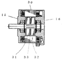
図2は軸を含む本発明の図1のモータの断面図である。9,11,20、13は磁性体よりなる外周にNr個の歯を有する回転子であり軸方向の厚さは同一である。29は11と20の間に設けた導電材の円板または銅箔シートであり回転子9等の外径以下の円板状で中央部に軸14を通す穴を有した形状が望ましいが多角形やその変形でも良い。10、12は円盤状永久磁石で軸14の方向にお互いに逆極性となるように磁化される。例えば9と13がN極性で11、20がS極性のように磁化する。このとき9と13は歯位置は同じで11、20とは歯ピッチの1/2ずらして配置される。本発明に関するモータの回転子は単位回転子A(9、10、11で構成)とB(20、12、13で構成)の2組の単位回転子の軸方向での連結により構成されると表現したが、これは永久磁石10,12と2個使用してこの2個の永久磁石に挟まれた回転子11、20はその2個の両サイドに位置する回転子9,13に対し歯位置が1/2ずれた特殊回転子1個で構成されたものと表現しても同じである。そして2組の単位回転子AとBの間には29なる導電材円板が設けられて上述の特殊回転子1個で構成されたものである。
15、16はブラケットであり回転子を回転自在に保持する役割を有する。5は固定子コイルである。 この2組の永久磁石による特殊回転子を設ける理由は4主極固定子と通常のHB型回転子の組み合わせで発生するラジアル方向の不平衡電磁力を消去するためである。図1では2相式で示したが、これに限定するものではなく3相3主極、あるいは5相5主極の省主極固定子と2個の永久磁石による特殊回転子であってもよい。
FIG. 1 is a structural view seen from the axial direction of a rotating electrical machine by a combination of a stator of a two-phase four-main-pole machine, which is a reduced main pole structure stator of the present invention, and a special HB type rotor. However, the winding coil is not shown.
2 is a cross-sectional view of the motor of FIG. 1 of the present invention including a shaft.
図6、図7は従来の通常の2相HB型回転電機を示す図であり、図6は軸方向から見た図であり、30は2相8主極の固定子、31は回転子である。図7は図6の回転子軸を含む断面図である。この構造では回転子の永久磁石は33の1個であり、31,32は図2の9、11、13と同じ形状の回転子であり、お互いに歯ピッチの1/2ずらせた歯位置に構成されている。固定子は8主極で1個おきの4個に図示はしてないが1相分コイルが巻かれている。この場合、180度で反対位置にある主極は励磁電流で同極性となるように構成されているのでラジアル方向である法線方向の吸引力は常にキャンセルされ、回転子外周の接線方向のトルク成分のみが現れる。これに対し例えば図1の固定子に図7の回転子を組み合わせると、例えば回転子31がN極性として上側に引かれた場合、回転子のS極32は下側へ引かれ、ラジアル方向吸引力による不平衡電磁力所謂サイドプルによる偶力が発生し、振動や騒音を発生させ、位置決め精度も悪くする。これに対し図2の構成では軸方向で中央部の磁性材29から左右で回転子は対称となるので、あたかも2個の対称なHB回転子が不平衡電磁力の偶力を打ち消すように作用する。このためラジアル方向の不平衡電磁力による偶力を常にキャンセルする優れた効果を有するものである。その詳細原理は本願発明者の一人が発明した特許文献1,2に詳細に数式を用いて説明しているのでここではその詳細説明は省略する。本願の図1、図2の構成は2相HB式ステッピングモータであるが、3相や5相HB型ステッピングモータや2相、や3相等のブラシレスモータにも、あるいは同期電動機にも活用できる構成である。
6 and 7 are diagrams showing a conventional ordinary two-phase HB type rotating electrical machine, FIG. 6 is a view seen from the axial direction, 30 is a stator of two-phase eight main poles, and 31 is a rotor. is there. FIG. 7 is a cross-sectional view including the rotor shaft of FIG. In this structure, the rotor has one permanent magnet 33, 31 and 32 are rotors having the same shape as 9, 11, and 13 in FIG. It is configured. The stator has eight main poles, and every other four stators are wound with coils for one phase (not shown). In this case, since the main poles at the opposite positions at 180 degrees are configured to have the same polarity by the excitation current, the normal attraction force in the radial direction is always canceled, and the tangential torque on the outer periphery of the rotor Only ingredients appear. On the other hand, for example, when the rotor of FIG. 7 is combined with the stator of FIG. 1, for example, when the rotor 31 is pulled upward with N polarity, the S pole 32 of the rotor is pulled downward to attract in the radial direction. Unbalanced electromagnetic force due to force, a couple due to so-called side pull is generated, which generates vibration and noise, and deteriorates positioning accuracy. On the other hand, in the configuration of FIG. 2, the rotor is symmetrical on the left and right sides from the
本構造の2相4主極と8主極固定子に同一回転子を組み合わせた場合のトルクを前述した文献で説明したが再度説明する。
T1=N NriΦm
(1)
1相分トルクは(5)式で表される。Nrは回転子歯数、Nはコイル巻き数、iは電流、
Φmは回転子からの永久磁石の磁束のコイルとの鎖交磁束である。
両者同一線径で同一トータル巻数Ntとする。また回転子から出るトータル磁束量は両者の固定子の歯数が例えば48(8主極は8×6=48、4主極では4×12=48)と等しいとした場合は両者の固定子鉄心の磁気抵抗差を無視し同じ値のΦtと近似できるので8主極機、4主極機の各1主極の巻数、磁束を各々N8
、N4、Φ8、Φ4として、次式が成立する。
Φ8=Φt/8
(2)
Φ4=Φt/4
(3)
N8=Nt/8
(4)
N2=Nt/4
(5)
(1)〜(5)式より、8主極 4主極機のトルク、T8、T4は各々以下となる。
T8=2*4(Nt/8)Nri(ΦT/8)
=NtNriΦt/8
(6)
T2=2*2(Nt/4)Nri(Φt/4)
=NtNriΦr/4
(7)
(6)、(7)より、4主極機は従来の8主極機のモータより約2倍のトルクが出せることになる。
The torque when the same rotor is combined with the two-phase four main pole and the eight main pole stator of this structure has been described in the above-mentioned literature, but will be described again.
T1 = N NriΦm
(1)
The torque for one phase is expressed by equation (5). Nr is the number of rotor teeth, N is the number of coil turns, i is the current,
Φm is an interlinkage magnetic flux between the permanent magnet magnetic flux from the rotor and the coil.
Both have the same wire diameter and the same total number of turns Nt. The total amount of magnetic flux generated from the rotor is equal to, for example, 48 when the number of teeth of both stators is equal to 48 (8 × 6 = 48 for 8 main poles, 4 × 12 = 48 for 4 main poles). Neglecting the magnetic resistance difference of the iron core, it can be approximated to the same value of Φt, so the number of turns and the magnetic flux of each main pole of the 8-main pole machine and 4-main pole machine are N8
, N4, Φ8, Φ4, the following equation is established.
Φ8 = Φt / 8
(2)
Φ4 = Φt / 4
(3)
N8 = Nt / 8
(4)
N2 = Nt / 4
(5)
From the formulas (1) to (5), the torques of the 8
T8 = 2 * 4 (Nt / 8) Nri (Φ T / 8)
= NtNriΦt / 8
(6)
T2 = 2 * 2 (Nt / 4) Nri (Φt / 4)
= NtNriΦr / 4
(7)
From (6) and (7), the 4-main pole machine can output about twice the torque of the motor of the conventional 8-main pole machine.
この4主極の場合の望ましい回転子歯数Nrは以下の式から誘導される。
90/Nr=(−/+){(360/4)−360n/Nr} (8)
但しnは1以上の整数。
(8)式の左辺、及び右辺は本構成のステップ角を表すしこれを整理すると(9)式が得
られる。
Nr=4n±1
(9)
Nrは,2相4主極対称構造の望ましい形態となる。
例えばn=19でNr=75となり、2相機では(90/Nr)度がステップ角となる
ので、1.2度ステップ角で対称形の固定子の回転電機が得られる。
この場合は固定子が90度対称となるので積層時90度回転積みができる。回転積みが
できると、積厚の偏差の解消や珪素鋼鈑の磁気方向性のキャンセルができて良好なモータ
特性となる。望ましい形態ではないが、Nr=50は(9)式を満足しないため固定子は非対称形状となり90度回転積みは出来ないが、ステップ角1.8度の2相ステッピングモータとなる。
Desired rotor teeth N r in the case of the fourth main electrode is derived from the following equation.
90 / Nr = (− / +) {(360/4) −360n / Nr} (8)
However, n is an integer of 1 or more.
The left side and the right side of the equation (8) represent the step angles of this configuration, and when this is arranged, the equation (9) is obtained.
Nr = 4n ± 1
(9)
Nr is a desirable form of a two-phase four-main polar symmetric structure.
For example, when n = 19 and Nr = 75, and the two-phase machine has a step angle of (90 / Nr) degrees, a symmetrical stator rotating electric machine can be obtained with a 1.2 degree step angle.
In this case, since the stator is 90 degrees symmetrical, it can be rotated 90 degrees when stacked. If rotation stacking is possible, it is possible to eliminate the deviation of the stack thickness and cancel the magnetic direction of the silicon steel plate, and to obtain good motor characteristics. Although not desirable, Nr = 50 does not satisfy Equation (9), so the stator becomes asymmetrical and cannot be rotated 90 degrees, but a two-phase stepping motor with a step angle of 1.8 degrees.
図2で永久磁石は2個使用するので、低グレード磁石でも高いトルクが得られることを従来の2相8主極式の磁石1個使用の(図6、図7の構成)場合と比較して示す。従来の2相8主極式で使用する永久磁石は希土類磁石でネオジム磁石で残留磁束密度Brが1.3[T]を使用していた。これに対し、本願の場合は2相4主極で磁石が2個なので、磁石のBrは次式で得られる。
Br=1.3[T]×(1/2)(3/2)(4/8)=0.4875[T] (10)
式(10)の(1/2)は1個の磁石で励磁する回転子の外周面積が同一サイズの従来
の8主極と組み合わせた通常のHB型回転子と比較して略1/2になるため永久磁石から発生する磁束も半分でよいので磁石の面積が同じなら磁石の磁束密度は半分でよいとの理由、(3/2)は永久磁石の磁路長さが半減するために鉄心部でのパーミアンスが単純約2倍となるが、エアギャップや磁路の磁束密度の低下を考慮してトータルでパーミアンスが約3/2倍に近似したものである。(4/8)は(4主極/8主極)を意味しトルクは前述した(6)式と(7)式の関係から主極数に反比例することによるものである。
この(10)式におけるBrの値の磁石でBrが1.3[T](テスラ)のネオジム
磁石を使用した8主極モータと同程度のトルクが得られることになる。式(10)の結果
はコンピユターでの磁場解析結果とほぼ一致している。
このBrの値はフェライト磁石に相当する。フェライト磁石はBrが0.5[T]で保
持力Hcj=275KA/m程度でその減磁曲線は磁束密度を垂直に保持力を水平に取っ
た座標の第二象限で直線となり、磁路に組まれた永久磁石のパーミアンス係数を勾配とし
た原点を通過する直線と減磁曲線との交点が動作点となるがその動作点磁束密度はほぼ永
久磁石のBrに比例することから近似的に(6)式が成立する。フェライト磁石は希土類
磁石に比べて極めて安価であり、2個使用してもネオジム磁石より安くなる。即ち0.5
[T]以下の磁石で十分実用トルクが得られる。0.5[T]以下の磁石であれば乾式や
湿式の焼結フェライト磁石に限らず樹脂をバインダーとしたボンド(プラスチック)磁石
でもよい。焼結フェライト磁石では例えば外形25mmで厚みは2mm程度が量産する限
度であり、それより薄いと割れ不良が多発する。これをボンド磁石にすれば割れ不良は解
決する。
2相4巻き線極固定子と前述の2連回転子で不平衡電磁力を抑えながら0.5[T]以下のローグレードの永久磁石を採用することにより、従来の高価なネオジム焼結磁石やサマリユムコバルト磁石のような希土類磁石を採用した同サイズモータに対しトルクを同等あるいは倍増することも可能であり今までにはない画期的な新技術といえる。
Since two permanent magnets are used in Fig. 2, the fact that high torque can be obtained even with low grade magnets is compared with the case of using a conventional two-phase 8-main pole type magnet (configuration in Figs. 6 and 7). Show. The conventional permanent magnet used in the two-phase 8-main pole type is a rare earth magnet, a neodymium magnet, and a residual magnetic flux density Br of 1.3 [T]. On the other hand, in the case of the present application, since there are two magnets with two phases and four main poles, Br of the magnet is obtained by the following equation.
Br = 1.3 [T] × (1/2) (3/2) (4/8) = 0.4875 [T] (10)
In equation (10), (1/2) is approximately ½ the outer peripheral area of the rotor excited by one magnet compared to a conventional HB type rotor combined with a conventional eight main pole of the same size. Therefore, the magnetic flux generated from the permanent magnet may be halved, so if the magnet area is the same, the magnetic flux density of the magnet may be halved. (3/2) is the iron core because the magnetic path length of the permanent magnet is halved. The permeance at the portion is simply about twice, but the permeance is approximated to about 3/2 times in total in consideration of the decrease in the air gap and the magnetic flux density of the magnetic path. (4/8) means (4 main poles / 8 main poles), and the torque is due to being inversely proportional to the number of main poles based on the relationship between the expressions (6) and (7).
A torque equivalent to that of an 8-main pole motor using a neodymium magnet having a Br value of 1.3 [T] (Tesla) and having a Br value in the equation (10) can be obtained. The result of the equation (10) almost coincides with the magnetic field analysis result in the computer.
The value of Br corresponds to a ferrite magnet. The ferrite magnet has a Br of 0.5 [T] and a holding force Hcj of about 275 KA / m, and its demagnetization curve becomes a straight line in the second quadrant of the coordinates where the magnetic flux density is perpendicular and the holding force is taken horizontally, The operating point is the intersection of a straight line passing through the origin with the permeance coefficient of the assembled permanent magnet as the gradient and the demagnetizing curve, but the operating point magnetic flux density is approximately proportional to Br of the permanent magnet (approximately ( 6) Equation is established. Ferrite magnets are extremely cheap compared to rare earth magnets, and even if two are used, they are cheaper than neodymium magnets. Ie 0.5
[T] Sufficient practical torque can be obtained with the following magnets. If it is a magnet of 0.5 [T] or less, it is not limited to a dry or wet sintered ferrite magnet, but may be a bond (plastic) magnet using a resin as a binder. In sintered ferrite magnets, for example, an outer diameter of 25 mm and a thickness of about 2 mm are the limit for mass production, and if it is thinner than that, crack defects frequently occur. If this is used as a bond magnet, the crack defect is solved.
By adopting a low-grade permanent magnet of 0.5 [T] or less while suppressing unbalanced electromagnetic force with the two-phase four-winding pole stator and the above-described two-line rotor, a conventional expensive neodymium sintered magnet Torque can be increased or reduced by the same size as the same size motors using rare earth magnets such as samarium cobalt magnets.
しかし、図2に示す構成の回転電機の2個の永久磁石をお互いに軸方向に反対方向の逆磁化させるには従来の空芯コイルでは困難である。この解決策の1つとしては図2で永久磁石10と12を予め、永久磁石単体で磁化したものをお互いに極性が逆方向になるように回転子を組み立て、更に固定子に組み込めばよい。しかしこの方法では回転子組み立て時に鉄粉を回転子に吸引したり、固定子内径部に回転子を挿入する祭に固定子と吸引接触し切子や塵を固定子内に介在させ信頼性を低下させるものとなる。
However, it is difficult with the conventional air-core coil to reversely magnetize the two permanent magnets of the rotating electrical machine having the configuration shown in FIG. 2 in the opposite directions in the axial direction. One solution is to assemble the rotor in such a way that the
これに対し、図3により本発明による着磁方式を説明する。前述した省主極固定子と2個の永久磁石による特殊回転子で構成されたHB型回転電機をその軸14を芯として包み込むように磁性体よりなる2個の軸方向に配置された設定着磁用磁路AとBから構成される。着磁される回転電機は図1、図2に示したものであるのでその部品には図1,2と同じ番号が付してある。設定着磁用磁路Aは図3の1、2なる環状ヨークであり4なる絶縁体ボビンに巻かれた環状の着磁コイル3とよりなる。コイル3に磁化電流を流して、ヨーク1から軸14の方向に突き出た部分から該ブラケット15を貫通させた磁化磁束を磁性体回転子9を貫通させて永久磁石10を貫通させ磁性体回転子11に流入させる。この磁化磁束はコイル3により作られるためコイル3の周りで閉ループを作ろうとする。そのためこの磁化磁束は一部は回転子9から永久磁石10を通過しないで直接磁性体固定子18に入りヨーク2を経由してヨーク1に戻る。しかし通常回転子9等は珪素鋼鈑より構成されるためその飽和磁束密度の1.5{T}程度を超えればそれ以上の大半の磁化磁束は永久磁石10を貫通し11に達し18なる磁性体固定子を経由してヨーク2からヨーク1に戻るので永久磁石10は着磁されることになる。このように該設定着磁用磁路Aにより軸方向で略1/2のモータ部とモータ側面と外周を短絡した磁性体磁路を環状磁化コイル3で励磁し、片方の永久磁石をほぼ軸方向に磁化できる。この場合15なるブラケットやボールベアリンブ17は磁性体であれば貫通磁化磁束は大きく出来るがブラケット15がアルミニウム等の非磁性体の場合は大きなエアギャップが介在することになり磁化磁束を十分に磁石10に到達させるためにはヨーク1の軸方向に突き出た部分とその突き出た部分の外周に巻かれたコイル3の存在がキーポイントとなる。そのためコイルの断面形状は図示のような絶縁体4に内部に段を設けた形状が望ましい。このようにして単位回転子Aを磁化する。しかし十分に磁化磁束を単位回転子Aの永久磁石10に通そうとするとその一部は漏洩磁束となり単位回転子Bの磁性体回転子20及び永久磁石12、磁性体回転子13をも通過して、単位回転子Bの永久磁石12を所望の極性とは逆の単位回転子Aの永久磁石10と同じ方向に磁化する。この場合、導電性円板29があると、この漏洩磁束が29を貫通し始めるとそれを打ち消すように導電性円板に渦電流が発生し単位回転子B側の永久磁石が磁化されるのを防止するように作用することになる。
また同様に絶縁体8に巻かれたコイル7に磁化電流を流して、ヨーク19から軸14の方向に突き出た部分から該ブラケット16、ボールベアリング17を経由して貫通させた磁化磁束を磁性体回転子13を貫通させて永久磁石12を前述の片側の永久磁石10とは軸方向に逆極性になるように貫通させ磁性体回転子20に流入させる。同様の理由によりこの磁化磁束は回転子20から固定子18を経由してヨーク6、ヨーク19へ戻る閉磁路を構成するので永久磁石12も磁化されることになる。この場合にも、一部の磁束は漏洩して単位回転子Aの既に磁化されている永久磁石10を減磁させようとする。この場合も同じく、導電性円板29があると、この漏洩磁束が29を貫通し始めるとそれを打ち消すように導電性円板に渦電流が発生し単位回転子A側の永久磁石が減磁されるのを防止するように作用することになる。
本方式では磁性体着磁ヨークとして1,2あるいは6、19の他に回転子9、11、20、13、固定子18を使用する。従って磁化磁束密度は回転子や固定子の構成材料の珪素鋼鈑の飽和磁束密度の1.5{T}程度では 残留磁束密度Brが1.2{T}程度のネオジム焼結磁石には磁化力が不足する場合があるが、前述したBrが0.5{T}程度であるフェライト磁石を本構造の永久磁石に用いた場合は十分適した着磁方式となる。 尚ヨーク2とヨーク6は別物の合体でも2と6は一体品でもよい。
ヨーク1,2と9,11、18で構成する閉磁路を設定着磁用磁路A、ヨーク19、ヨーク6回転子13、20、固定子18で構成される閉磁路を設定着磁用磁路Bとすれば、設定着磁用磁路AとBは、適当な磁化力で時間差を設けて磁化してもよい。その場合、磁化力が強すぎると永久磁石10と永久磁石12が同方向に磁化されるので磁路に合わせた最適な磁化力で行うことになる。あるいはやはり適当な磁化力で同時磁化してもよい。これらの場合、前述した導電性円板29が有効に働くことになる。
図3で着磁コイルは回転子軸と同心の環状コイルで示したが、固定子外周部に回転子軸と略垂直に設けた該着磁用磁路A及びBの端部の回転子外周円盤部の一部をカットして回転子軸と略垂直のヨーク部に直接着磁コイルを巻きつけてもよいし、回転子軸と同心の環状コイルとの併設コイルとしてそれらのコイルを直列あるいは並列させてもよい。
On the other hand, the magnetization system according to the present invention will be described with reference to FIG. The HB type rotating electric machine composed of the above-mentioned main-main pole stator and a special rotor composed of two permanent magnets is set in two axial directions made of magnetic material so as to wrap the
Similarly, a magnetizing current is passed through the
In this system,
A closed magnetic path composed of the
In FIG. 3, the magnetizing coil is shown as an annular coil concentric with the rotor shaft, but the outer periphery of the rotor at the end of the magnetizing magnetic paths A and B provided substantially perpendicular to the rotor shaft on the outer periphery of the stator. A part of the disk portion may be cut and a magnetized coil may be wound directly on a yoke portion that is substantially perpendicular to the rotor shaft, or these coils may be connected in series or as a side coil with a concentric annular coil. You may make it parallel.
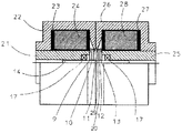
図4は回転子にまで完成させた後に着磁工程を設ける場合の方法を示したものである。前述したモータ完成後完成では回転子や固定子の珪素鋼鈑を磁路の一部に使用する。そのため回転機に広く使用される無方向性珪素鋼鈑の磁束密度の約1.5{T}程度の磁化磁束密度ではネオジム焼結磁石等の残留磁束密度が1.2{T}程度の永久磁石の磁化には十分でない場合が起きる。またこの方法では、回転子を磁化後に固定子への挿入時には固定子との接触が発生し易いが、前述のモータ完成後磁化の長所の一部を犠牲にして、永久磁石の十分な磁化力が必要なケースもあるため、回転子完成状態での磁化の方法を示したものである。この場合は珪素鋼鈑を使用しないので、ヨークに飽和磁束密度の高い純鉄等を使用できる。純鉄の飽和磁束密度は2.2{T}程度なので、ネオジム焼結磁石等でも磁化可能レベルとなる。21、25は回転子軸方向に磁化磁束を作るヨークでその外周に磁化コイル24,28が配置されて磁化磁束が軸方向に発射されるようにしてある。回転子の構成は図2と同じなので部品名とその番号は同じとしてある。22,26は外部ヨークであり軸14を同心として円筒状に構成し適当に分割して絶縁ボビン23,27及び前述の磁化コイル24,28を内蔵する。22,26の端部は回転子外周と接触あるいは近接対向させる。21、と22、26と25は密着させる。この場合、両サイドのブラケットが無いので磁化磁束を図3の場合より十分に永久磁石10,12に与えられる。このとき、導電材29による効果は前述したモータ完成後着磁と同じである。ボールベアリング17を挿入する前の段階でこの磁化を行えば21、25の回転子9,13との対向面積を増加出来、更に磁化を容易にすることが出来る。この場合も、2個の磁化コイルは同時通電でも時間差通電でもよい。もし図1、図2のモータをアウターロータ型とした場合でも、本方式に準じた着磁をすることが出来る。また図4で着磁コイルは回転子軸と同心の環状コイルで示したが、固定子外周部に回転子軸と略垂直に設けた該着磁用磁路a及びbの端部の回転子外周円盤部の一部をカットして回転子軸と略垂直のヨーク部に直接着磁コイルを巻きつけてもよいし、回転子軸と同心の環状コイルとの併設コイルとしてそれらのコイルを直列あるいは並列させてもよい。
FIG. 4 shows a method in which a magnetizing step is provided after the rotor is completed. When the motor is completed after completion of the motor, a silicon steel plate of a rotor or a stator is used as a part of the magnetic path. Therefore, the permanent magnetic flux density of neodymium sintered magnet or the like is about 1.2 {T} at the magnetic flux density of about 1.5 {T} of the magnetic flux density of the non-oriented silicon steel plate widely used for rotating machines. There are cases where it is not sufficient to magnetize the magnet. Also, with this method, contact with the stator is likely to occur when the rotor is inserted into the stator after magnetization, but sufficient magnetizing force of the permanent magnet is sacrificed at the expense of some of the advantages of magnetization after completion of the motor. Therefore, the method of magnetization in the completed rotor state is shown. In this case, since a silicon steel plate is not used, pure iron or the like having a high saturation magnetic flux density can be used for the yoke. Since the saturation magnetic flux density of pure iron is about 2.2 {T}, it can be magnetized even with a neodymium sintered magnet or the like.
モータ完成後着磁の別の本発明を図5にて説明する。図3は予め2個の設定磁化磁路を設けるものであるが、図5は1個の設定磁化磁路のみで磁化を行うものである。図5にて1、2はヨークであり、図3の片側の設定磁路Aのみと基本的には同じであるが2のモータ固定子外周と対向するヨーク2の軸方向の厚みは中央の回転子11の軸方向厚み全部と対向するように厚く設定してある。図5の状態で適当な磁化力で磁化し永久磁石10のみを磁化する。磁化力が強すぎると永久磁石12も磁化されるので磁路に合わせた最適な磁化力で行うことになる。この後、モータをヨーク部から引き抜き軸方向を反転させてヨーク部に挿入して同様に磁化すればよい。この場合、磁化に多少時間を要するが、磁化ヨークや装置が図3の場合より小形に出来ることの他にヨーク2のモータ部との対向厚さを最適に選び、軸方向にモータ磁化位置を正位置と反転位置で最適化する等の最適磁化改善もできる。このとき、導電材29による効果は前述したモータ完成後着磁と同じである。
Another embodiment of the magnetization after completion of the motor will be described with reference to FIG. FIG. 3 is provided with two set magnetization magnetic paths in advance, but FIG. 5 performs magnetization with only one set magnetization magnetic path. In FIG. 5,
本発明により磁化した回転電機は安価な磁石で高トルクが出せるのでOA機器である複写機やプリンターの用途に対し安価で高トルクなモータの提供が可能であり、エアギャップも大きく出来るので低振動のアクチュエータとなり、工業的に大きな寄与が期待される。その他、医療機器、FA機器、ロボット、遊戯機械、住宅設備機器への応用も大いに期待される。 Since the rotating electric machine magnetized according to the present invention can produce a high torque with an inexpensive magnet, it is possible to provide a low-cost and high-torque motor for the use of copying machines and printers that are office automation equipment, and the air gap can be increased, resulting in low vibration. It is expected to make a significant industrial contribution. In addition, application to medical equipment, FA equipment, robots, amusement machines, and housing equipment is also highly expected.
1、2、6,19、21,22,25,26 : 着磁ヨーク、
4、8、23,27 : 絶縁ボビン
3、7、24,28 : 着磁コイル、
9、11,13、20、31,32 : 回転子、
5 : コイル
14 : 回転軸、
10、12、33 : 永久磁石
29 : 導電材
15,16 : ブラケット
17 : ボールベアリング
18、30 : 固定子
1, 2, 6, 19, 21, 22, 25, 26: magnetized yoke,
4, 8, 23, 27: Insulated bobbins
3, 7, 24, 28: Magnetized coil,
9, 11, 13, 20, 31, 32: rotor,
5: Coil 14: Rotating shaft,
10, 12, 33: Permanent magnet 29:
Claims (5)
Priority Applications (4)
| Application Number | Priority Date | Filing Date | Title |
|---|---|---|---|
| JP2006266227A JP5128800B2 (en) | 2006-09-29 | 2006-09-29 | Hybrid permanent magnet rotating electric machine |
| US11/677,886 US7779532B2 (en) | 2006-02-28 | 2007-02-22 | Manufacturing method of hybrid permanent magnet type electric rotating machine |
| CN2007101097875A CN101064464B (en) | 2006-02-28 | 2007-02-27 | Hybrid permanent magnet type electric rotating machine and manufacturing method thereof |
| EP07250810A EP1826886B1 (en) | 2006-02-28 | 2007-02-27 | Hybrid permanent magnet type electric rotating machine and manufacturing method thereof |
Applications Claiming Priority (1)
| Application Number | Priority Date | Filing Date | Title |
|---|---|---|---|
| JP2006266227A JP5128800B2 (en) | 2006-09-29 | 2006-09-29 | Hybrid permanent magnet rotating electric machine |
Publications (3)
| Publication Number | Publication Date |
|---|---|
| JP2008086176A JP2008086176A (en) | 2008-04-10 |
| JP2008086176A5 JP2008086176A5 (en) | 2009-10-01 |
| JP5128800B2 true JP5128800B2 (en) | 2013-01-23 |
Family
ID=39356447
Family Applications (1)
| Application Number | Title | Priority Date | Filing Date |
|---|---|---|---|
| JP2006266227A Expired - Fee Related JP5128800B2 (en) | 2006-02-28 | 2006-09-29 | Hybrid permanent magnet rotating electric machine |
Country Status (1)
| Country | Link |
|---|---|
| JP (1) | JP5128800B2 (en) |
Families Citing this family (3)
| Publication number | Priority date | Publication date | Assignee | Title |
|---|---|---|---|---|
| JP4745416B2 (en) * | 2009-04-09 | 2011-08-10 | 日本電産サーボ株式会社 | Hybrid permanent magnet rotating electric machine |
| DE102009047239B4 (en) | 2008-12-02 | 2015-02-12 | Nidec Servo Corp. | Permanent magnet excited electric machine |
| KR102341859B1 (en) * | 2020-03-16 | 2021-12-21 | 계명대학교 산학협력단 | A electric motor using stator asymmetric shoe and its manufacturing method |
Family Cites Families (4)
| Publication number | Priority date | Publication date | Assignee | Title |
|---|---|---|---|---|
| JPH03195344A (en) * | 1989-12-22 | 1991-08-26 | Shibaura Eng Works Co Ltd | Magnetizer for step motor |
| JPH08266033A (en) * | 1995-03-23 | 1996-10-11 | Hitachi Ltd | Stepping motor equipped with magnetizer, and method of incorporating its rotor |
| JP3762981B2 (en) * | 2001-10-16 | 2006-04-05 | 日本サーボ株式会社 | Permanent magnet rotating electric machine |
| JP4000144B2 (en) * | 2004-12-15 | 2007-10-31 | 山洋電気株式会社 | Rotor for hybrid type stepping motor and manufacturing method thereof |
-
2006
- 2006-09-29 JP JP2006266227A patent/JP5128800B2/en not_active Expired - Fee Related
Also Published As
| Publication number | Publication date |
|---|---|
| JP2008086176A (en) | 2008-04-10 |
Similar Documents
| Publication | Publication Date | Title |
|---|---|---|
| JP5491484B2 (en) | Switched reluctance motor | |
| JP2007236073A (en) | Hybrid rotary electric machine | |
| US7535145B2 (en) | Axial air gap-type electric motor | |
| US7595575B2 (en) | Motor/generator to reduce cogging torque | |
| JP5332082B2 (en) | motor | |
| JP6415758B2 (en) | Magnetization method, rotor, electric motor and scroll compressor | |
| JP6407456B2 (en) | Rotor, magnetizing method, electric motor and scroll compressor | |
| JP2009072010A (en) | Axial gap type coreless rotating machine | |
| WO2017110688A1 (en) | Motor | |
| JP2009136046A (en) | Toroidally-wound dynamo-electric machine | |
| JP2011188579A (en) | Permanent magnet synchronous machine | |
| JP2011078202A (en) | Axial gap motor | |
| JP2008092715A (en) | Permanent magnet motor | |
| US7779532B2 (en) | Manufacturing method of hybrid permanent magnet type electric rotating machine | |
| JP2013132124A (en) | Core for field element | |
| WO2018066084A1 (en) | Motor and air-conditioning device | |
| JP7047337B2 (en) | Permanent magnet type rotary electric machine | |
| JP5128800B2 (en) | Hybrid permanent magnet rotating electric machine | |
| JP4080273B2 (en) | Permanent magnet embedded motor | |
| JP2007089304A (en) | Permanent-magnet type rotating electric machine | |
| JP2007228771A (en) | Permanent magnet type motor | |
| JP2008187863A (en) | Axial gap rotary electric machine and compressor | |
| JP7193422B2 (en) | Rotating electric machine and manufacturing method of rotating electric machine | |
| JP5015621B2 (en) | Permanent magnet type two-phase rotating electric machine | |
| JP7459155B2 (en) | Rotating electric machine and its field element manufacturing method |
Legal Events
| Date | Code | Title | Description |
|---|---|---|---|
| A521 | Written amendment |
Free format text: JAPANESE INTERMEDIATE CODE: A523 Effective date: 20090819 |
|
| A621 | Written request for application examination |
Free format text: JAPANESE INTERMEDIATE CODE: A621 Effective date: 20090819 |
|
| A131 | Notification of reasons for refusal |
Free format text: JAPANESE INTERMEDIATE CODE: A131 Effective date: 20120105 |
|
| A977 | Report on retrieval |
Free format text: JAPANESE INTERMEDIATE CODE: A971007 Effective date: 20120111 |
|
| A521 | Written amendment |
Free format text: JAPANESE INTERMEDIATE CODE: A523 Effective date: 20120305 |
|
| TRDD | Decision of grant or rejection written | ||
| A01 | Written decision to grant a patent or to grant a registration (utility model) |
Free format text: JAPANESE INTERMEDIATE CODE: A01 Effective date: 20121016 |
|
| A01 | Written decision to grant a patent or to grant a registration (utility model) |
Free format text: JAPANESE INTERMEDIATE CODE: A01 |
|
| A61 | First payment of annual fees (during grant procedure) |
Free format text: JAPANESE INTERMEDIATE CODE: A61 Effective date: 20121101 |
|
| R150 | Certificate of patent or registration of utility model |
Free format text: JAPANESE INTERMEDIATE CODE: R150 Ref document number: 5128800 Country of ref document: JP Free format text: JAPANESE INTERMEDIATE CODE: R150 |
|
| FPAY | Renewal fee payment (event date is renewal date of database) |
Free format text: PAYMENT UNTIL: 20151109 Year of fee payment: 3 |
|
| R250 | Receipt of annual fees |
Free format text: JAPANESE INTERMEDIATE CODE: R250 |
|
| R250 | Receipt of annual fees |
Free format text: JAPANESE INTERMEDIATE CODE: R250 |
|
| R250 | Receipt of annual fees |
Free format text: JAPANESE INTERMEDIATE CODE: R250 |
|
| R250 | Receipt of annual fees |
Free format text: JAPANESE INTERMEDIATE CODE: R250 |
|
| R250 | Receipt of annual fees |
Free format text: JAPANESE INTERMEDIATE CODE: R250 |
|
| LAPS | Cancellation because of no payment of annual fees |