JP2009072010A - Axial gap type coreless rotating machine - Google Patents
Axial gap type coreless rotating machine Download PDFInfo
- Publication number
- JP2009072010A JP2009072010A JP2007238979A JP2007238979A JP2009072010A JP 2009072010 A JP2009072010 A JP 2009072010A JP 2007238979 A JP2007238979 A JP 2007238979A JP 2007238979 A JP2007238979 A JP 2007238979A JP 2009072010 A JP2009072010 A JP 2009072010A
- Authority
- JP
- Japan
- Prior art keywords
- coil
- cross
- section
- axial gap
- gap type
- Prior art date
- Legal status (The legal status is an assumption and is not a legal conclusion. Google has not performed a legal analysis and makes no representation as to the accuracy of the status listed.)
- Granted
Links
- 239000011248 coating agent Substances 0.000 claims description 15
- 238000000576 coating method Methods 0.000 claims description 15
- 238000009413 insulation Methods 0.000 claims description 7
- 238000004804 winding Methods 0.000 abstract description 73
- 239000012212 insulator Substances 0.000 abstract 1
- 230000000052 comparative effect Effects 0.000 description 10
- XEEYBQQBJWHFJM-UHFFFAOYSA-N Iron Chemical group [Fe] XEEYBQQBJWHFJM-UHFFFAOYSA-N 0.000 description 8
- 230000004907 flux Effects 0.000 description 7
- RYGMFSIKBFXOCR-UHFFFAOYSA-N Copper Chemical compound [Cu] RYGMFSIKBFXOCR-UHFFFAOYSA-N 0.000 description 6
- 229910052802 copper Inorganic materials 0.000 description 6
- 239000010949 copper Substances 0.000 description 6
- 238000004519 manufacturing process Methods 0.000 description 5
- 238000000034 method Methods 0.000 description 5
- 239000002320 enamel (paints) Substances 0.000 description 4
- 230000001965 increasing effect Effects 0.000 description 4
- 238000010586 diagram Methods 0.000 description 3
- 230000020169 heat generation Effects 0.000 description 3
- 229910001172 neodymium magnet Inorganic materials 0.000 description 3
- 230000007423 decrease Effects 0.000 description 2
- 230000003247 decreasing effect Effects 0.000 description 2
- 239000000463 material Substances 0.000 description 2
- 238000010248 power generation Methods 0.000 description 2
- 229920001342 Bakelite® Polymers 0.000 description 1
- 239000000853 adhesive Substances 0.000 description 1
- 230000001070 adhesive effect Effects 0.000 description 1
- 239000004637 bakelite Substances 0.000 description 1
- 230000000694 effects Effects 0.000 description 1
- 229920006332 epoxy adhesive Polymers 0.000 description 1
- 230000001939 inductive effect Effects 0.000 description 1
- 230000005415 magnetization Effects 0.000 description 1
- 230000000149 penetrating effect Effects 0.000 description 1
- 230000002093 peripheral effect Effects 0.000 description 1
- 102200029231 rs11551768 Human genes 0.000 description 1
- 238000004088 simulation Methods 0.000 description 1
- 125000006850 spacer group Chemical group 0.000 description 1
- 230000001360 synchronised effect Effects 0.000 description 1
Images


Classifications
-
- H—ELECTRICITY
- H02—GENERATION; CONVERSION OR DISTRIBUTION OF ELECTRIC POWER
- H02K—DYNAMO-ELECTRIC MACHINES
- H02K3/00—Details of windings
- H02K3/46—Fastening of windings on the stator or rotor structure
- H02K3/47—Air-gap windings, i.e. iron-free windings
-
- H—ELECTRICITY
- H02—GENERATION; CONVERSION OR DISTRIBUTION OF ELECTRIC POWER
- H02K—DYNAMO-ELECTRIC MACHINES
- H02K21/00—Synchronous motors having permanent magnets; Synchronous generators having permanent magnets
- H02K21/12—Synchronous motors having permanent magnets; Synchronous generators having permanent magnets with stationary armatures and rotating magnets
- H02K21/24—Synchronous motors having permanent magnets; Synchronous generators having permanent magnets with stationary armatures and rotating magnets with magnets axially facing the armatures, e.g. hub-type cycle dynamos
-
- H—ELECTRICITY
- H02—GENERATION; CONVERSION OR DISTRIBUTION OF ELECTRIC POWER
- H02K—DYNAMO-ELECTRIC MACHINES
- H02K16/00—Machines with more than one rotor or stator
Landscapes
- Engineering & Computer Science (AREA)
- Power Engineering (AREA)
- Windings For Motors And Generators (AREA)
- Permanent Magnet Type Synchronous Machine (AREA)
- Insulation, Fastening Of Motor, Generator Windings (AREA)
- Iron Core Of Rotating Electric Machines (AREA)
Abstract
Description
本発明は、モータや発電機等の同期式の永久磁石回転機で、回転子と固定子とが回転軸方向に対向したアキシャルギャップ型回転機に関する。 The present invention relates to an axial gap type rotating machine that is a synchronous permanent magnet rotating machine such as a motor or a generator and in which a rotor and a stator are opposed to each other in a rotation axis direction.
永久磁石回転機は、構造上の分類からラジアルギャップ型とアキシャルギャップ型とがある。ラジアルギャップ型は、回転子の周方向に複数の永久磁石を配置し、永久磁石の磁極は径方向に向いており、永久磁石に対向するように固定子が配置されている。一般に固定子は回転子に対向する面に複数の歯状をもつ鉄芯にコイルが巻かれた構造をしている鉄芯を用いることで回転子磁極からの磁束を効率よくコイルに鎖交することができ、モータの場合には大きなトルク、発電機の場合には大きな電圧を生ずることができる。反面、鉄芯を用いるためにコギングトルクや鉄芯のヒステリシス損失に基づくロストルクを生じ、初動トルクを大きくするという問題がある。初動トルクが大きいと、例えば風力発電機に用いた際に微風では回転できず発電できない。 Permanent magnet rotating machines are classified into radial gap type and axial gap type according to the structural classification. In the radial gap type, a plurality of permanent magnets are arranged in the circumferential direction of the rotor, the magnetic poles of the permanent magnets are oriented in the radial direction, and the stator is arranged to face the permanent magnets. In general, the stator uses an iron core having a structure in which a coil is wound around an iron core having a plurality of teeth on the surface facing the rotor, so that the magnetic flux from the rotor magnetic pole is efficiently linked to the coil. It can produce a large torque in the case of a motor and a large voltage in the case of a generator. On the other hand, since the iron core is used, there is a problem that a loss torque based on the cogging torque and the hysteresis loss of the iron core is generated and the initial torque is increased. If the initial torque is large, for example, when it is used in a wind power generator, it cannot rotate with a breeze and cannot generate power.
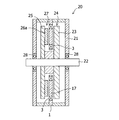
鉄芯を取り除けばこのような問題はなくなるが、磁気効率が悪くなるのでラジアルギャップ型では大きな出力が得られない。そこで、図8に示すようなアキシャルギャップ型が考えられる。 If the iron core is removed, such a problem will be eliminated, but since the magnetic efficiency is deteriorated, a large output cannot be obtained with the radial gap type. Therefore, an axial gap type as shown in FIG. 8 can be considered.
図8において、回転軸(シャフト)22には、表面に複数の永久磁石26aを備えた円盤状磁性体(ロータヨーク)25がスペーサを介して複数段取り付けられ一体化しており、回転子27を構成している。各ロータヨークの間に形成される空隙にはコイル3を備えた固定子1が配置され,ハウジング21に固定されている。回転軸22はハウジング21によりベアリング28を介して回動可能に支持されている。この構造であればコイル3に鉄芯を用いなくても永久磁石26aの磁極面を大きくすることで出力を大きくとることができる。アキシャルギャップ型の回転機では、コイルに鉄芯を用いない(コアレスと呼ぶ)構造であるので、初動トルクが無く、高出力な回転機を得ることができる。コアレス回転機は、巻線のインダクタンスが小さく低インピーダンスになるので高回転になっても内部損失が少なく高出力高効率になる。例えば、コアレス発電機として用いた場合、内部損失はインピーダンスと電流の積であるので、インピーダンスが小さい分、大きな電流を供給できることになる。このように大電流を供給したい用途には、コアレス回転機は有利である。なお、流せる電流の大きさは、コイルの発熱を制限するために巻線の断面積で決められ、巻線の断面積1mm2当たり5〜15Aとなっている。
コイルは断面円形の巻線で巻くより、断面角型の巻線で巻いた方がコイルの占有率を向上することができ、高出力化が図れる。そこで本発明者らは、30Aの電流を得るために、断面寸法1.6mm×1.25mm、断面積2mm2の角線を巻いたコイルを製作し、アキシャルギャップ型のコアレス発電機として3600rpmで回転させたところ、負荷に何も接続しない状態、即ちコイルに電流が流れていないにも拘わらずコイルが発熱した。この発熱は発電機の内部損失となり、発電効率を低下させる要因となる。本発明者らが発熱の原因を究明したところ、磁場がコイル巻線を鎖交する際に、巻線内部に環状に渦電流が流れて発熱することが分かった。渦電流を低減する方法として、巻線を細くすることが考えられるが、これでは大きな電流を流すことができない。 The coil occupancy can be improved and the output can be increased by winding the coil with a winding having a square cross section rather than winding with a winding having a circular cross section. In order to obtain a current of 30 A, the present inventors manufactured a coil wound with a square wire having a cross-sectional dimension of 1.6 mm × 1.25 mm and a cross-sectional area of 2 mm 2 at 3600 rpm as an axial gap type coreless generator. When rotated, the coil generated heat despite nothing being connected to the load, that is, no current flowing through the coil. This heat generation causes an internal loss of the generator, which causes a decrease in power generation efficiency. The inventors have investigated the cause of heat generation and found that when a magnetic field links the coil windings, an eddy current flows annularly inside the windings to generate heat. As a method for reducing the eddy current, it is conceivable to make the winding thin. However, a large current cannot be passed through this.
本発明は、上記現状に鑑み、巻線内に発生する渦電流を減らし、大きな電流を供給できる高出力高効率のアキシャルギャップ型回転機を提供することを目的とする。 In view of the above situation, an object of the present invention is to provide a high-output and high-efficiency axial gap type rotating machine that can reduce eddy current generated in a winding and supply a large current.
本発明者は、上記課題を解決するために鋭意検討を行い、巻線内に発生する渦電流を減らし、大きな電流を供給できる高出力高効率のアキシャルギャップ型回転機を実現した。すなわち、本発明に係るアキシャルギャップ型回転機は、
ハウジングと、該ハウジング内に回転自在に支持された回転軸と、前記回転軸の軸方向に間隔を置いて対向配置された回転盤を備え前記回転軸と一体に回動可能な2段の回転子であって、前記対向配置された回転盤の対向面の少なくとも一面において、前記回転軸を中心とする円周上に磁極面が回転軸に対して垂直になるように永久磁石を配置している回転子と、前記対向配置された回転盤が形成する空隙に配置されハウジングに固定された固定盤、および、前記回転盤の永久磁石が配置された円周と相対する前記固定盤の円周上に配置されたコイルを備えた固定子とを備えたアキシャルギャップ型の回転機であって、前記コイルは、長方形断面を有するコイル素線を断面の長辺を揃えてかつ/または短辺を揃えて2本以上束ねてなる巻線からなり、前記巻線は、外周を絶縁被覆されており、前記コイル素線の断面の長辺と前記永久磁石の磁極面とが垂直になるように巻き回されていることを特徴とする。
The present inventor has intensively studied to solve the above-mentioned problems, and has realized an axial gap type rotary machine with high output and high efficiency that can reduce eddy current generated in the winding and supply a large current. That is, the axial gap type rotating machine according to the present invention is
A two-stage rotation that includes a housing, a rotary shaft that is rotatably supported in the housing, and a rotating disk that is disposed to face the rotary shaft at an interval in the axial direction and is rotatable integrally with the rotary shaft. A permanent magnet is disposed on at least one of the opposed surfaces of the opposedly arranged rotating disk so that a magnetic pole surface is perpendicular to the rotational axis on a circumference centered on the rotational axis. A fixed platen disposed in a gap formed by the opposed rotary plate and fixed to the housing, and a circumference of the fixed plate facing a circumference on which the permanent magnet of the rotary plate is arranged An axial gap type rotating machine including a stator having a coil disposed thereon, wherein the coil has a rectangular wire with a long side of the cross section aligned and / or a short side. Or two or more windings that are bundled together Becomes, the winding periphery and a is an insulating coating, characterized in that the pole faces of the long sides and the permanent magnet of the cross section of the coil wire is wound so as to be perpendicular.
本発明に係るアキシャルギャップ型回転機は、他の態様として、ハウジングと、該ハウジング内に回転自在に支持された回転軸と、前記回転軸の軸方向に間隔を置いて対向配置された端部回転盤を備え、前記回転軸と一体に回動可能な第1と第2の端部回転子と、前記第1と第2の端部回転子が形成する空隙に配置された回転盤、および、前記回転盤の両面において、前記回転軸を中心とする円周上に磁極面が回転軸に対して垂直になるように配置された永久磁石を備え、前記回転軸と一体に回動可能な少なくとも1段の両面磁石回転子と、前記第1端部回転子、前記少なくとも1段の両面磁石回転子、および、前記第2端部回転子が形成する各空隙に配置されハウジングに固定された固定盤、ならびに、前記回転盤の永久磁石が配置された円周と相対する前記固定盤の円周上に配置されたコイルを備えた固定子とを備えたアキシャルギャップ型の回転機であって、前記コイルは、長方形断面を有するコイル素線を断面の長辺を揃えてかつ/または短辺を揃えて2本以上束ねてなる巻線からなり、前記巻線は、外周を絶縁被覆されており、前記コイル素線の断面の長辺と前記永久磁石の磁極面とが垂直になるように巻き回されていることを特徴とする。
本発明に係るアキシャルギャップ型回転機は、他の態様として、上記第1と第2の端部回転子の端部回転盤の対向面に磁極面が回転軸に対して垂直になるように配置された永久磁石とを備えたものとすることもできる。
As another aspect, the axial gap type rotating machine according to the present invention includes a housing, a rotary shaft rotatably supported in the housing, and an end portion opposed to the rotary shaft at an interval in the axial direction. First and second end rotors, each of which includes a rotating disk and capable of rotating integrally with the rotating shaft; and a rotating disk disposed in a gap formed by the first and second end rotors; The both sides of the rotating disk are provided with permanent magnets arranged on the circumference centering on the rotating shaft so that the magnetic pole surface is perpendicular to the rotating shaft, and can be rotated integrally with the rotating shaft. At least one stage of double-sided magnet rotor, the first end rotor, the at least one stage of double-sided magnet rotor, and the second end rotor are disposed in each gap and fixed to the housing. The fixed plate and the permanent magnet of the rotating plate are arranged An axial gap type rotating machine including a stator provided with a coil disposed on a circumference of the fixed plate opposed to a circumference, wherein the coil includes a coil wire having a rectangular cross section and a length of the cross section. The windings are formed by bundling two or more wires with the sides aligned and / or the short sides aligned, and the windings are insulated on the outer periphery, and the long side of the coil wire cross section and the permanent magnet The magnetic pole surface is wound so as to be perpendicular to the magnetic pole surface.
As another aspect, the axial gap type rotating machine according to the present invention is arranged such that the magnetic pole surface is perpendicular to the rotation axis on the opposing surfaces of the end rotary disks of the first and second end rotors. It is also possible to provide a permanent magnet.
本発明に係るアキシャルギャップ型回転機は、前記コイル素線の断面形状が、断面の長辺の長さ/断面の短辺の長さ≧5の関係にあることが好適である。
本発明に係るアキシャルギャップ型回転機は、前記コイル素線の断面の短辺の長さが、0.5mm以下であることが好適である。
本発明に係るアキシャルギャップ型回転機は、前記コイル素線の各々が絶縁被覆されているものであってもよい。
In the axial gap type rotating machine according to the present invention, it is preferable that the cross-sectional shape of the coil wire has a relationship of the length of the long side of the cross section / the length of the short side of the cross section ≧ 5.
In the axial gap type rotating machine according to the present invention, it is preferable that the length of the short side of the cross section of the coil wire is 0.5 mm or less.
In the axial gap type rotating machine according to the present invention, each of the coil strands may be covered with insulation.
本発明により、大電流を流すことができる巻線断面積でありながら、高出力高効率なアキシャルギャップ型コアレス回転機を得ることができる。 According to the present invention, it is possible to obtain an axial gap type coreless rotating machine with high output and high efficiency while having a winding cross-sectional area through which a large current can flow.
以下、本発明について、図面を参照してさらに詳細に説明する。
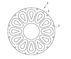
本発明にかかるアキシャルギャップ型回転機の固定子を図1に示す。図1で固定子1は、コイルベース(固定盤)2の回転軸を中心とする円周上に12個のコイル3を等間隔に配置している。コイルの数は、回転子の極数やコイル繋ぎを単相あるいは三相するかで選ばれ、磁極数に対して単相の場合は、1:1で、三相交流(コアレス)の場合は、磁極数:コイル数=4:3が一般的で16:9、20:12等もある。図1の例では、16極の回転子で三相出力を得るために12個のコイルを三相結線したものである。
なお、固定子は、図1に示したようにコイルベース2の回転軸を中心とする1つの円周上に配置したものに限られず、コイルベース2において、回転軸を中心とする2つ以上の異径同心円の各円周上に配置した、いわゆる複周構成を採用することもできる。かかる場合においては、固定盤のコイルが配置された異径同心円に相対する回転盤の異径同心円の各円周上に永久磁石が備えられていることになる。
Hereinafter, the present invention will be described in more detail with reference to the drawings.
FIG. 1 shows a stator of an axial gap type rotating machine according to the present invention. In FIG. 1, the
The stator is not limited to the one arranged on one circumference centered on the rotation axis of the
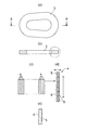
上記固定子に使用されるコイルの巻線構造について図2でさらに詳細に説明する。図2(a)〜(c)に示すように、コイル3は外周表面に絶縁被覆6が施された板状のコイル巻線4を巻いたものとなっている。さらに図2(d)に示すように、板状コイル巻線4は、断面長方形のコイル素線5をその断面の長辺および短辺を揃えて合計18本束ねて構成されている。
コイル巻線4の絶縁被覆6の厚さは、渦電流低減の観点から、好ましい範囲は、0〜50μmであり、より好ましい範囲は、20μm〜30μmである。また巻線の絶縁被覆は、エナメルコーティングによって施される。
The coil winding structure used for the stator will be described in more detail with reference to FIG. As shown in FIGS. 2 (a) to 2 (c), the
From the viewpoint of reducing eddy current, the thickness of the
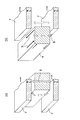
図3および図4では、アキシャルギャップ型回転機の駆動時において、上記板状コイル巻線4の内部に渦電流が流れることを説明する。図3(a)では、前記回転子の永久磁石7が、回転軸の回転に伴って前記回転軸を中心とする円周上に配設された特定のコイル3の巻線4の上方に達した状態を示す。このときのA―A断面図が図4(a)に相当する。図3(b)では、さらに回転子が回転して、永久磁石7が特定のコイル3の巻線4の上方から遠ざかろうとしている。このときのB―B断面図が図4(b)に相当する。図3(a)から図3(b)への過程において、図4(a)(b)に示すように、巻線4の内部を貫く磁束8が刻々減少する。この磁束の減少を妨げるように巻線4の内部に渦電流9(誘導電流)が流れる。渦電流9は、磁束が貫く面に多く流れるので、磁束に平行な面より磁極面に平行な面、図4(b)では上下面に多く流れる。そこで本発明者らは、アキシャルギャップ型回転機のコイルでは、磁極面に平行な面を細分化すると渦電流経路が寸断されるので渦電流の低減に効果的となると考え、上述のように同一断面形状を有する2本以上のコイル素線をその断面の長辺かつ/または短辺を揃えて束ね合わせることによって巻線を得ることを着想した。
3 and 4, it will be described that an eddy current flows inside the plate coil winding 4 when the axial gap type rotating machine is driven. In FIG. 3A, the
巻線を構成するコイル素線5は長方形断面を有していることが好ましい。個々の素線5自体も、図2(e)に示すように絶縁被覆6されていることが渦電流低減の観点から好ましいが、絶縁被覆6が厚いと巻線の占積率を下げてしまい出力低下につながるので、薄い絶縁被膜がよく、例えば、エナメル線を好適に採用することができる。なお、絶縁被膜が無い場合でも渦電流低減効果はあるので、コイル素線5自体の絶縁被膜は必須条件ではない。コイル素線5に絶縁被覆6を施す場合、その厚さは、渦電流低減の観点から好ましくは、0〜50μm、より好ましくは、20μm〜30μmである。またコイル素線5の絶縁被覆には、巻線の絶縁被覆と同様の材料を採用することができる。
素線の寸法としては、渦電流が流れ難い値が選ばれる。渦電流が流れ難い値は、磁極数や回転数、磁場強度等によって変わり、有限要素法等を用いた磁場シミュレーションによって算出することができる。
素線の断面の短辺の長さは、0.5mm以下が好ましい。素線の断面長辺の寸法を小さくすることも渦電流低減につながるが、素線を細くしすぎると巻線化が難しく、巻線の占積率を低下することにもなるので、素線の断面の長辺即ちコイルを回転機に配置したときに永久磁石の磁極面に対して垂直な辺は、素線の断面の短辺即ち永久磁石の磁極面に対して平行な辺ほど小さな値をとる必要はない。前記コイル素線の断面形状は、断面の長辺の長さ/断面の短辺の長さ≧5の関係にあることが好ましい。
The
As the dimension of the element wire, a value at which eddy current does not easily flow is selected. The value at which the eddy current hardly flows varies depending on the number of magnetic poles, the number of rotations, the magnetic field strength, and the like, and can be calculated by a magnetic field simulation using a finite element method or the like.
The length of the short side of the cross section of the strand is preferably 0.5 mm or less. Decreasing the dimension of the long side of the cross section of the wire also leads to eddy current reduction. However, if the wire is made too thin, it is difficult to form a wire and the space factor of the wire will be reduced. The longer side of the cross section of the wire, that is, the side perpendicular to the magnetic pole surface of the permanent magnet when the coil is arranged on the rotating machine, the smaller the shorter side of the wire cross section, that is, the side parallel to the magnetic pole surface of the permanent magnet. There is no need to take The cross-sectional shape of the coil wire is preferably in the relationship of the length of the long side of the cross section / the length of the short side of the cross section ≧ 5.
図5および図6には、本発明にかかる回転機で用いられるコイルの他の態様を示している。図5では、巻線を構成するコイル素線は、長方形断面となっている点で図2の態様と共通しているが、正方形断面の巻線を巻き回して構成されている点において図2の態様と相違する。
図6では、長方形断面の巻線を巻き回して構成されている点において図2の態様と共通するが、コイル素線の断面の短辺が図2に比べて厚くなっている。
ただし何れのコイルも、巻線を構成する素線の断面において、断面の短辺の長さは、0.5mm以下になるようにしている。
5 and 6 show another embodiment of the coil used in the rotating machine according to the present invention. In FIG. 5, the coil wire constituting the winding is the same as that of FIG. 2 in that it has a rectangular cross section, but in the point that it is configured by winding a winding having a square cross section. This is different from the embodiment.
6 is the same as the aspect of FIG. 2 in that it is formed by winding a winding having a rectangular cross section, but the short side of the cross section of the coil wire is thicker than that of FIG.
However, in any of the coils, the length of the short side of the cross section of the wire constituting the winding is 0.5 mm or less.
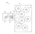
図7では、上述したコイル巻線およびコイルの製造方法の一例を示す。図7にかかるコイル製造機10は、7つのコイル素線源14を備え、回転によってコイル素線5を送り出す素線供給部11と、該素線供給部から供給される素線5を互いに反対方向に回転する2つの回転体15によって巻き込み束ねて1本の断面角型の巻線4を作る素線集合部12と、該素線集合部で得られたコイル巻線4を中空のコイル枠16に巻きとるコイル巻き付け部13とを備えている。例えば、かかる製造装置によってコイルを得ることができる。なお、素線集合部12とコイル巻き付け部との間には、素線集合部12で得られた巻線に絶縁被覆を施す被覆部を設けてもよい。
In FIG. 7, an example of the coil winding mentioned above and the manufacturing method of a coil is shown. The
上記コイルを備えた固定子は、例えば、以下の図8、図10、図11および図12に示すアキシャルギャップ型回転機に好適に用いることができる。
図8にかかるアキシャルギャップ型回転機20は、ハウジング21と、該ハウジング21内に回転自在に支持された回転軸22と、前記回転軸22の軸方向に間隔を置いて対向配置された回転盤23,25を備え前記回転軸と一体に回動可能な2段の回転子であって、前記対向配置された回転盤23,25の対向面の一面において、前記回転軸を中心とする円周上に磁極面が回転軸に対して垂直になるように永久磁石26aを配置している回転子24,27と、前記対向配置された回転盤23,25が形成する空隙に配置されハウジングに固定された固定盤1、および、前記回転盤の永久磁石が配置された円周と相対する前記固定盤の円周上に配置されたコイル3を備えた固定子とを備えている。
前記回転子の永久磁石から発生する磁束は、前記回転軸の回転に伴って、同心円状に配設された各コイル3の内部を断続的に鎖交するようになっている。
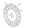
図9には、上記アキシャルギャップ型回転機20で用いられる回転子27が開示されている。回転子27は、ロータヨーク25の表面上に16個の永久磁石7を磁極が交互になるように配置している。永久磁石の数は偶数個になっている。永久磁石としては、強力な磁力をもつNd−Fe−B系の焼結磁石を用いることで高出力になる。
The stator provided with the said coil can be used suitably for the axial gap type | mold rotary machine shown in the following FIG.8, FIG.10, FIG.11 and FIG.
An axial gap
The magnetic flux generated from the permanent magnet of the rotor is intermittently linked inside the
FIG. 9 discloses a
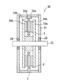
図10にかかるアキシャルギャップ型回転機30は、対向配置された回転盤35a,35bの対向面の両面において、回転軸32を中心とする円周上に磁極面が回転軸に対して垂直になるように永久磁石34a,34bを配置している点において図8の態様と相違している。
図10の態様は、回転盤(ロータヨーク)の両方の表面に永久磁石を配置しているので、図8の態様に比べて磁気効率を向上することができる。なお、回転盤は、1つの磁石を回転盤に形成された貫通孔のなかに嵌め込んで形成してもよい。
In the axial gap
In the embodiment of FIG. 10, permanent magnets are arranged on both surfaces of the rotating disk (rotor yoke), so that the magnetic efficiency can be improved as compared with the embodiment of FIG. The rotating disk may be formed by fitting one magnet into a through hole formed in the rotating disk.
図11にかかるアキシャルギャップ型回転機40は、ハウジング41と、該ハウジング内に回転自在に支持された回転軸42と、前記回転軸42の軸方向に間隔を置いて対向配置された端部回転盤43a,43bを備え、前記回転軸と一体に回動可能な第1と第2の端部回転子と、前記第1と第2の端部回転子が形成する空隙に配置された回転盤44、および、前記回転盤44の両面において、前記回転軸42を中心とする円周上に磁極面が回転軸に対して垂直になるように配置された永久磁石45を備え、前記回転軸と一体に回動可能な少なくとも1段の両面磁石回転子と、前記第1端部回転子、前記少なくとも1段の両面磁石回転子、および、前記第2端部回転子が形成する各空隙に配置されハウジングに固定された固定盤1、ならびに、前記回転盤の永久磁石が配置された円周と相対する前記固定盤の円周上に配置されたコイル3を備えた固定子とを備えている。
図12にかかるアキシャルギャップ型回転機50は、第1と第2の端部回転子の端部回転盤53a,53bの対向面に磁極面が回転軸に対して垂直になるように配置された永久磁石54とを備えている点で、図11にかかる態様と相違している。
図11や図12に示すように軸方向に回転子と固定子を複数個並べると、出力がコイルの数だけ増えて、より高出力な回転機となる。図11と図12は、3つの回転子と2つの固定子を配置したものである。固定子の数は2個以上の整数で、回転子の数は固定子の数に1加えたものになる。
An axial gap
The axial gap
As shown in FIGS. 11 and 12, when a plurality of rotors and stators are arranged in the axial direction, the output increases by the number of coils, resulting in a higher output rotating machine. 11 and 12 show three rotors and two stators. The number of stators is an integer of 2 or more, and the number of rotors is one added to the number of stators.
以下、実施例にて詳しく説明する。なお、Nd2−Fe14−B系の永久磁石を用いた場合について説明するが、本発明はNd−Fe−B系磁石に限るものではない。本永久磁石の特性は、Br:13.7kG,iHc:16kOe,(BH)max:46MGOeであった。
比較例1
まず、図10に示すアキシャルギャップ型回転機を発電機とした場合の発電量並びに損失を測定した。発電機の構造は16極12コイルであり、図9は、ロータヨーク27に永久磁石7を配置して回転子25を得た状態を示す。ロータヨーク27としては、材質がS15Cで外径200mm、厚さ5mmの円盤を用いた。永久磁石7としては、材質が上記Nd−Fe−B系磁石で、大きさが幅20mm、長さ35mm、磁化方向の厚さ3mmのものを用いた。ロータヨーク27表面に磁極面がN極S極交互に16個の磁石を配置し、弾性接着剤(EP001、セメダイン社製)で接着した。磁石は図10に示すように空隙(ギャップ)をはさんで逆極の磁石と対向させた。ギャップの大きさは8mmで、ギャップには固定子1を配置した。
固定子1には、図1に示すように、材質がベークライト製で厚さが5mmのコイルベース2に30ターン巻かれたコイル3が12個収められている。コイル3は三相結線で、各相4個のコイル3を直列に接続したものをスター結線した。なお、各コイル3はコイルベース2にエポキシ系接着剤(EW2040、住友3M社製)で固定した。コイルの断面は固定子を図10に示すアキシャルギャップ型回転機に組み込んだときに永久磁石の磁極面に対して垂直な辺が5mm、永久磁石の磁極面に対して平行な辺が12mmとなっている。本比較例では、断面の短辺が1.25mm、断面の長辺が1.6mmの長方形断面を有する1本の素線(材質:銅、絶縁被覆あり)を巻線として、図10に示すアキシャルギャップ型回転機に組み込んだときに各コイル素線の断面の短辺が永久磁石の磁極面に対して垂直になるように巻いた。巻線の断面積は2mm2である。
得られたアキシャルギャップ型発電機の回転子を毎分3600回転で回転させ、負荷をつないで線電流30A、線間電圧100V、三相出力5200Wを得た。発電機の入力側にトルクメータを取付け、回転数とトルクから発電機の入力電力を測定した。入力は6500Wであった。巻線の銅損は、その抵抗値と電流値から300Wであるので、残りの損失の1000Wが巻線の渦電流損失になり、その他の損失である機械損や風損はほとんど無視できることを確認できた。
Hereinafter, the embodiment will be described in detail. Although a case where an Nd 2 —Fe 14 —B based permanent magnet is used will be described, the present invention is not limited to an Nd—Fe—B based magnet. The characteristics of the permanent magnet were Br: 13.7 kG, iHc: 16 kOe, (BH) max: 46 MGOe.
Comparative Example 1
First, the amount of power generation and the loss when the axial gap type rotating machine shown in FIG. 10 was used as a generator were measured. The structure of the generator is 16 poles and 12 coils, and FIG. 9 shows a state in which the
As shown in FIG. 1, the
The rotor of the obtained axial gap generator was rotated at 3600 revolutions per minute and connected to a load to obtain a line current of 30 A, a line voltage of 100 V, and a three-phase output of 5200 W. A torque meter was attached to the input side of the generator, and the input power of the generator was measured from the rotation speed and torque. The input was 6500W. Since the copper loss of the winding is 300W from its resistance and current value, the remaining loss of 1000W becomes the eddy current loss of the winding, and other losses such as mechanical loss and windage loss are almost negligible. did it.
比較例2
断面の長辺が5mm、断面の短辺が0.4mmの1本のコイル素線を巻線として、図10に示すアキシャルギャップ型回転機に組み込んだときにコイル素線の断面の長辺が永久磁石の磁極面に対して垂直になるように巻いたほかは比較例1と同様にした。
得られたアキシャルギャップ型発電機の回転子を毎分3600回転で回転させ、負荷をつないで線電流30A、線間電圧100V、三相出力5200Wを得た。この時の入力電力は5700Wであった。巻線の銅損は、その抵抗値と電流値から300Wであるので、残りの損失の200Wが巻線の渦電流損失になることがわかった。巻線の素線を空隙の直角方向に細くすると、巻線の渦電流損失を低減できることがわかった。
Comparative Example 2
When a single coil element wire having a long side of the cross section of 5 mm and a short side of the cross section of 0.4 mm is used as a winding and incorporated in the axial gap type rotating machine shown in FIG. 10, the long side of the cross section of the coil element wire is Comparative Example 1 was performed except that the permanent magnet was wound so as to be perpendicular to the magnetic pole surface of the permanent magnet.
The rotor of the obtained axial gap generator was rotated at 3600 revolutions per minute and connected to a load to obtain a line current of 30 A, a line voltage of 100 V, and a three-phase output of 5200 W. The input power at this time was 5700W. Since the copper loss of the winding is 300 W from the resistance value and the current value, it was found that the remaining loss of 200 W becomes the eddy current loss of the winding. It was found that the eddy current loss of the winding can be reduced by making the wire of the winding thin in the direction perpendicular to the gap.
実施例1
断面の長辺が5mm、断面の短辺が0.1mmのコイル素線を断面の長辺を揃えて4列束ね合わせることによって、断面の長辺が5mm、断面の短辺が0.4mmの素線集合体を得、これにエナメル被覆を施して巻線を得たほかは比較例2と同様とした。
得られたアキシャルギャップ型発電機の回転子を毎分3600回転で回転させ、負荷をつないで線電流30A、線間電圧100V、三相出力5200Wを得た。この時の入力電力は5620Wであった。巻線の銅損は、その抵抗値と電流値から300Wであるので、残りの損失の120Wが巻線の渦電流損失になることがわかった。比較例2に比べて巻線の渦電流損失を低減でき、高効率な発電機を得ることができた。
Example 1
A long strand of the cross section is 5 mm, and a short side of the cross section is 0.4 mm by bundling together four rows of coil strands having a long side of the cross section of 5 mm and a short side of the cross section of 0.1 mm. The same procedure as in Comparative Example 2 was conducted except that a wire assembly was obtained and enamel coating was applied thereto to obtain a winding.
The rotor of the obtained axial gap generator was rotated at 3600 revolutions per minute and connected to a load to obtain a line current of 30 A, a line voltage of 100 V, and a three-phase output of 5200 W. The input power at this time was 5620W. Since the copper loss of the winding is 300 W from the resistance value and the current value, it was found that the remaining loss of 120 W becomes the eddy current loss of the winding. Compared with Comparative Example 2, the eddy current loss of the winding could be reduced, and a highly efficient generator could be obtained.
実施例2
断面の長辺が1.25mm、断面の短辺が0.4mmのコイル素線を断面の短辺を揃えて4列束ね合わせることによって、断面の長辺が5mm、断面の短辺が0.4mmの素線集合体を得、これにエナメル被覆を施して巻線を得たほかは比較例2と同様とした。
得られたアキシャルギャップ型発電機の回転子を毎分3600回転で回転させ、負荷をつないで線電流30A、線間電圧100V、三相出力5200Wを得た。この時の入力電力は5610Wであった。巻線の銅損は、その抵抗値と電流値から300Wであるので、残りの損失の110Wが巻線の渦電流損失になる。比較例に比べて巻線の渦電流損失を低減でき、高効率な発電機を得ることができた。
Example 2
A coil strand having a long side of the cross section of 1.25 mm and a short side of the cross section of 0.4 mm is bundled by aligning the short sides of the cross section and four rows are bundled, so that the long side of the cross section is 5 mm and the short side of the cross section is 0. The same procedure as in Comparative Example 2 was conducted, except that a 4 mm strand assembly was obtained and enamel coating was applied thereto to obtain a winding.
The rotor of the obtained axial gap generator was rotated at 3600 revolutions per minute and connected to a load to obtain a line current of 30 A, a line voltage of 100 V, and a three-phase output of 5200 W. The input power at this time was 5610W. Since the copper loss of the winding is 300 W from its resistance value and current value, the remaining loss of 110 W becomes the eddy current loss of the winding. Compared with the comparative example, the eddy current loss of the winding could be reduced, and a highly efficient generator could be obtained.
実施例3
断面の長辺が1.25mm、断面の短辺が0.1mmのコイル素線を断面の長辺および短辺を揃えて4行×4列の計16本束ね合わせることによって、断面の長辺が5mm、断面の短辺が0.4mmの素線集合体を得、これにエナメル被覆を施して巻線を得たほかは比較例2と同様とした。
得られたアキシャルギャップ型発電機の回転子を毎分3600回転で回転させ、負荷をつないで線電流30A、線間電圧100V、三相出力5200Wを得た。この時の入力電力は5550Wであった。巻線の銅損は、その抵抗値と電流値から300Wであるので、残りの損失の50Wが巻線の渦電流損失になることがわかった。比較例1に比べ、巻線の渦電流損失を1/20、比較例2に比べ1/4にできたのみならず、実施例1や実施例2よりもさらに高効率な発電機を得ることができた。
Example 3
The long side of the cross section is obtained by bundling a total of 16 coil wires having a long side of the cross section of 1.25 mm and a short side of the cross section of 0.1 mm, with the long side and the short side of the cross section aligned. Was obtained, and a wire assembly having a short side of 0.4 mm was obtained, and enamel coating was applied thereto to obtain a winding.
The rotor of the obtained axial gap generator was rotated at 3600 revolutions per minute and connected to a load to obtain a line current of 30 A, a line voltage of 100 V, and a three-phase output of 5200 W. The input power at this time was 5550 W. Since the copper loss of the winding is 300 W from the resistance value and the current value, it was found that the remaining loss of 50 W becomes the eddy current loss of the winding. Compared to Comparative Example 1, not only can the eddy current loss of the windings be reduced to 1/20, compared to Comparative Example 2, but also a generator with higher efficiency than that of Example 1 or Example 2 can be obtained. I was able to.
1 固定子
2 コイルベース
3 コイル
4 コイル巻線
5 コイル素線
6 絶縁被覆
7 永久磁石
8 巻線内部を鎖交する磁束
9 渦電流の向き
10 コイル製造機
11 素線供給部
12 素線集合部
13 コイル巻き付け部
14 コイル素線源
15 回転体
16 コイル枠
20,30,40,50 アキシャルギャップ型回転機
21,31,41,51 ハウジング
22,32,42,52 回転軸
23、25,33a,33b,44 回転盤(ロータヨーク)
24、27 回転子
26a,34a,34b,45,54,56 永久磁石
28 ベアリング
43a,43b,53a,53b 端部回転盤
1
24, 27
Claims (6)
該ハウジング内に回転自在に支持された回転軸と、
前記回転軸の軸方向に間隔を置いて対向配置された回転盤を備え前記回転軸と一体に回動可能な2段の回転子であって、前記対向配置された回転盤の対向面の少なくとも一面において、前記回転軸を中心とする円周上に磁極面が回転軸に対して垂直になるように永久磁石を配置している回転子と、
前記対向配置された回転盤が形成する空隙に配置されハウジングに固定された固定盤、および、前記回転盤の永久磁石が配置された円周と相対する前記固定盤の円周上に配置されたコイルを備えた固定子とを備えたアキシャルギャップ型の回転機であって、
前記コイルは、長方形断面を有するコイル素線を断面の長辺を揃えてかつ/または短辺を揃えて2本以上束ねてなる巻線からなり、前記巻線は、外周を絶縁被覆されており、前記コイル素線の断面の長辺と前記永久磁石の磁極面とが垂直になるように巻き回されているアキシャルギャップ型回転機。 A housing;
A rotating shaft rotatably supported in the housing;
A two-stage rotator provided with a rotating disk opposed to each other with an interval in the axial direction of the rotating shaft, and capable of rotating integrally with the rotating shaft, wherein at least a facing surface of the facing rotating disk On one surface, a rotor in which permanent magnets are arranged on a circumference centering on the rotation axis so that a magnetic pole surface is perpendicular to the rotation axis;
The fixed platen disposed in the gap formed by the opposedly arranged turntables and fixed to the housing, and arranged on the circumference of the fixed platen opposed to the circumference on which the permanent magnets of the rotary plate are arranged. An axial gap type rotating machine having a stator with a coil,
The coil is composed of two or more coil wires having a rectangular cross section with the long side of the cross section aligned and / or the short side aligned, and the outer periphery of the coil is covered with an insulation coating. The axial gap type rotating machine is wound so that the long side of the cross section of the coil wire is perpendicular to the magnetic pole surface of the permanent magnet.
該ハウジング内に回転自在に支持された回転軸と、
前記回転軸の軸方向に間隔を置いて対向配置された端部回転盤を備え、前記回転軸と一体に回動可能な第1と第2の端部回転子と、
前記第1と第2の端部回転子が形成する空隙に配置された回転盤、および、前記回転盤の両面において、前記回転軸を中心とする円周上に磁極面が回転軸に対して垂直になるように配置された永久磁石を備え、前記回転軸と一体に回動可能な少なくとも1段の両面磁石回転子と、
前記第1端部回転子、前記少なくとも1段の両面磁石回転子、および、前記第2端部回転子が形成する各空隙に配置されハウジングに固定された固定盤、ならびに、前記回転盤の永久磁石が配置された円周と相対する前記固定盤の円周上に配置されたコイルを備えた固定子とを備えたアキシャルギャップ型の回転機であって、
前記コイルは、長方形断面を有するコイル素線を断面の長辺を揃えてかつ/または短辺を揃えて2本以上束ねてなる巻線からなり、前記巻線は、外周を絶縁被覆されており、前記コイル素線の断面の長辺と前記永久磁石の磁極面とが垂直になるように巻き回されているアキシャルギャップ型回転機。 A housing;
A rotating shaft rotatably supported in the housing;
First and second end rotors, each of which includes an end rotating disk disposed opposite to each other with an interval in the axial direction of the rotating shaft, and is rotatable together with the rotating shaft;
On both sides of the rotating disk disposed in the gap formed by the first and second end rotors, and on both sides of the rotating disk, the magnetic pole surface is on the circumference centered on the rotating axis with respect to the rotating axis A permanent magnet arranged to be vertical, and at least one double-sided magnet rotor that can rotate integrally with the rotary shaft;
The first end rotor, the at least one-stage double-sided magnet rotor, the stationary platen disposed in each gap formed by the second end rotor and fixed to the housing, and the permanent plate of the rotary plate An axial gap type rotating machine comprising a stator provided with a coil arranged on the circumference of the stationary plate and the circumference arranged with the magnet,
The coil is composed of two or more coil wires having a rectangular cross section with the long side of the cross section aligned and / or the short side aligned, and the outer periphery of the coil is covered with an insulation coating. The axial gap type rotating machine is wound so that the long side of the cross section of the coil wire is perpendicular to the magnetic pole surface of the permanent magnet.
Priority Applications (8)
| Application Number | Priority Date | Filing Date | Title |
|---|---|---|---|
| JP2007238979A JP5033552B2 (en) | 2007-09-14 | 2007-09-14 | Axial gap type coreless rotating machine |
| US12/676,062 US8299676B2 (en) | 2007-09-14 | 2008-09-10 | Axial gap type coreless rotating machine |
| DK08831067.7T DK2190103T3 (en) | 2007-09-14 | 2008-09-10 | COREL FREE SHUTTER WITH SHIFT |
| CN200880106739.3A CN101809847B (en) | 2007-09-14 | 2008-09-10 | axial gap type coreless rotating machine |
| EP08831067.7A EP2190103B1 (en) | 2007-09-14 | 2008-09-10 | Axial gap type coreless rotating machine |
| ES08831067.7T ES2650231T3 (en) | 2007-09-14 | 2008-09-10 | Coreless rotary machine of the type with axial strike |
| PCT/JP2008/066310 WO2009034991A1 (en) | 2007-09-14 | 2008-09-10 | Axial gap type coreless rotating machine |
| TW097135217A TWI415367B (en) | 2007-09-14 | 2008-09-12 | Axial clearance type without core rotating machine |
Applications Claiming Priority (1)
| Application Number | Priority Date | Filing Date | Title |
|---|---|---|---|
| JP2007238979A JP5033552B2 (en) | 2007-09-14 | 2007-09-14 | Axial gap type coreless rotating machine |
Publications (2)
| Publication Number | Publication Date |
|---|---|
| JP2009072010A true JP2009072010A (en) | 2009-04-02 |
| JP5033552B2 JP5033552B2 (en) | 2012-09-26 |
Family
ID=40451998
Family Applications (1)
| Application Number | Title | Priority Date | Filing Date |
|---|---|---|---|
| JP2007238979A Expired - Fee Related JP5033552B2 (en) | 2007-09-14 | 2007-09-14 | Axial gap type coreless rotating machine |
Country Status (8)
| Country | Link |
|---|---|
| US (1) | US8299676B2 (en) |
| EP (1) | EP2190103B1 (en) |
| JP (1) | JP5033552B2 (en) |
| CN (1) | CN101809847B (en) |
| DK (1) | DK2190103T3 (en) |
| ES (1) | ES2650231T3 (en) |
| TW (1) | TWI415367B (en) |
| WO (1) | WO2009034991A1 (en) |
Cited By (10)
| Publication number | Priority date | Publication date | Assignee | Title |
|---|---|---|---|---|
| JP2011239621A (en) * | 2010-05-13 | 2011-11-24 | Kobe Steel Ltd | Magneto-striction type ultrasonic motor |
| JP2012120319A (en) * | 2010-11-30 | 2012-06-21 | Nisca Corp | Axial gap type rotating machine and axial gap type generator |
| JP2015505233A (en) * | 2011-12-16 | 2015-02-16 | 沈坤元 | Disc type composite multi-combination 3D permanent magnet motor |
| WO2016174895A1 (en) * | 2015-04-28 | 2016-11-03 | 日本電産株式会社 | Motor |
| JP2018515061A (en) * | 2015-05-19 | 2018-06-07 | グリーンスパー リニューアブルズ リミテッド | Permanent magnet generator configuration method |
| JP2019518411A (en) * | 2016-06-15 | 2019-06-27 | グリーンスパー リニューアブルズ リミテッド | Axial flux generator |
| JP2020137230A (en) * | 2019-02-18 | 2020-08-31 | 株式会社ごとう | Brushless motor |
| WO2021141354A1 (en) | 2020-01-10 | 2021-07-15 | Samsung Electronics Co., Ltd. | Cleaner |
| KR20210091036A (en) | 2020-01-10 | 2021-07-21 | 삼성전자주식회사 | Cleaner |
| KR20240060219A (en) * | 2022-10-28 | 2024-05-08 | 오원섭 | Axial Flux Multi Stage Motor |
Families Citing this family (20)
| Publication number | Priority date | Publication date | Assignee | Title |
|---|---|---|---|---|
| USRE46449E1 (en) | 2007-07-09 | 2017-06-20 | Clearwater Holdings, Ltd. | Electromagnetic machine with independent removable coils, modular parts and self sustained passive magnetic bearing |
| US10038349B2 (en) * | 2008-08-15 | 2018-07-31 | Millennial Research Corporation | Multi-phase modular coil element for electric motor and generator |
| US10230292B2 (en) | 2008-09-26 | 2019-03-12 | Clearwater Holdings, Ltd | Permanent magnet operating machine |
| JP2014511098A (en) * | 2011-02-25 | 2014-05-01 | センゼン アントウサン スペシャル マシン アンド エレクトリカル カンパニー,リミテッド | Rare earth permanent magnet coreless generator unit |
| US20150229194A1 (en) | 2012-08-27 | 2015-08-13 | Albus Technologies Ltd. | Rotor with magnet pattern |
| US10505412B2 (en) | 2013-01-24 | 2019-12-10 | Clearwater Holdings, Ltd. | Flux machine |
| JP2015019546A (en) | 2013-07-12 | 2015-01-29 | 株式会社東芝 | Axial gap type permanent magnet electrical rotating machine, and manufacturing method for the same |
| CN103475176A (en) * | 2013-08-22 | 2013-12-25 | 浙江双民科技有限公司 | Vehicle-mounted coreless generator |
| GB2520516B (en) * | 2013-11-21 | 2021-08-25 | Time To Act Ltd | Direct drive generator for renewable energy applications |
| MX363001B (en) | 2014-07-23 | 2019-03-01 | Clearwater Holdings Ltd | Flux machine. |
| CN104218713A (en) * | 2014-09-03 | 2014-12-17 | 洛阳市贝叶机电有限公司 | Stator structure for permanent magnet coreless brushless motor |
| PL233865B1 (en) * | 2017-07-28 | 2019-12-31 | Equelo Spólka Z Ograniczona Odpowiedzialnoscia | Electric machine |
| CN115188604A (en) | 2017-09-08 | 2022-10-14 | 清水控股有限公司 | System and method for enhancing electrical storage |
| JP7433223B2 (en) | 2017-10-29 | 2024-02-19 | クリアウォーター ホールディングス,リミテッド | Modular electromagnetic machine and manufacturing method |
| CN108087234B (en) * | 2018-01-03 | 2023-09-22 | 广东美芝制冷设备有限公司 | Compressor and refrigeration equipment |
| US11632015B2 (en) * | 2018-08-28 | 2023-04-18 | Boston Scientific Scimed, Inc. | Axial flux motor for percutaneous circulatory support device |
| DE102019202630A1 (en) * | 2019-02-27 | 2020-08-27 | Fraunhofer-Gesellschaft zur Förderung der angewandten Forschung e.V. | Electric motor |
| CN113691094A (en) * | 2020-05-19 | 2021-11-23 | 陆继荣 | Rare-earth permanent-magnet axial double-magnetic-circuit coreless generator |
| GB2595659A (en) * | 2020-06-01 | 2021-12-08 | Time To Act Ltd | Improvements to the performance of axial flux generators |
| CN116054517A (en) * | 2021-10-26 | 2023-05-02 | 励富创瑞士控股有限公司 | Energy-saving brushless micro-start generator |
Citations (3)
| Publication number | Priority date | Publication date | Assignee | Title |
|---|---|---|---|---|
| JPS55122308U (en) * | 1979-02-23 | 1980-08-30 | ||
| JPH11113204A (en) * | 1997-10-02 | 1999-04-23 | Hitachi Ltd | Stator coil of dynamo-electric machine |
| JPH11187635A (en) * | 1997-12-19 | 1999-07-09 | Sawafuji Electric Co Ltd | Flat rotating machine |
Family Cites Families (15)
| Publication number | Priority date | Publication date | Assignee | Title |
|---|---|---|---|---|
| US4371801A (en) * | 1978-10-11 | 1983-02-01 | General Electric Company | Method and apparatus for output regulation of multiple disk permanent magnet machines |
| JPS55122308A (en) | 1979-03-14 | 1980-09-20 | Yazaki Corp | High voltage resistance wire for preventing noise |
| US5945766A (en) * | 1996-01-18 | 1999-08-31 | Amotron Co., Ltd. | Coreless-type BLDC motor and method of producing stator assembly having axial vibration attenuation arrangement |
| US5744896A (en) * | 1996-05-21 | 1998-04-28 | Visual Computing Systems Corp. | Interlocking segmented coil array |
| US5982074A (en) * | 1996-12-11 | 1999-11-09 | Advanced Technologies Int., Ltd. | Axial field motor/generator |
| US5731649A (en) * | 1996-12-27 | 1998-03-24 | Caama+E,Otl N+Ee O; Ramon A. | Electric motor or generator |
| BR0017296A (en) * | 2000-08-02 | 2003-06-24 | Von Roll Isola Winding Systems | Windings for electrical machines with flexibly braided wire conductors |
| JP4782303B2 (en) | 2001-04-18 | 2011-09-28 | 株式会社スカイ電子 | Permanent magnet generator |
| DK1251624T3 (en) * | 2001-04-20 | 2009-04-20 | Converteam Ltd | Cooling of air gap winding in electric machines |
| US7098566B2 (en) * | 2001-05-24 | 2006-08-29 | Rajasingham Arjuna Indraes War | Axial gap electrical machine |
| JP2003348805A (en) | 2002-05-24 | 2003-12-05 | Nsk Ltd | Generator |
| JP2004208464A (en) * | 2002-12-26 | 2004-07-22 | Nissan Motor Co Ltd | Coil structure for electric motor |
| CN101019298B (en) * | 2004-03-14 | 2011-02-09 | 瑞佛路申电动机有限公司 | Brushless motor-generator and its production method |
| US7501733B2 (en) * | 2004-05-18 | 2009-03-10 | Seiko Epson Corporation | Electric machine |
| JP2006158024A (en) * | 2004-11-26 | 2006-06-15 | Sumitomo Electric Ind Ltd | Coil and its manufacturing method |
-
2007
- 2007-09-14 JP JP2007238979A patent/JP5033552B2/en not_active Expired - Fee Related
-
2008
- 2008-09-10 ES ES08831067.7T patent/ES2650231T3/en active Active
- 2008-09-10 CN CN200880106739.3A patent/CN101809847B/en not_active Expired - Fee Related
- 2008-09-10 US US12/676,062 patent/US8299676B2/en active Active
- 2008-09-10 WO PCT/JP2008/066310 patent/WO2009034991A1/en active Application Filing
- 2008-09-10 DK DK08831067.7T patent/DK2190103T3/en active
- 2008-09-10 EP EP08831067.7A patent/EP2190103B1/en not_active Not-in-force
- 2008-09-12 TW TW097135217A patent/TWI415367B/en not_active IP Right Cessation
Patent Citations (3)
| Publication number | Priority date | Publication date | Assignee | Title |
|---|---|---|---|---|
| JPS55122308U (en) * | 1979-02-23 | 1980-08-30 | ||
| JPH11113204A (en) * | 1997-10-02 | 1999-04-23 | Hitachi Ltd | Stator coil of dynamo-electric machine |
| JPH11187635A (en) * | 1997-12-19 | 1999-07-09 | Sawafuji Electric Co Ltd | Flat rotating machine |
Cited By (14)
| Publication number | Priority date | Publication date | Assignee | Title |
|---|---|---|---|---|
| JP2011239621A (en) * | 2010-05-13 | 2011-11-24 | Kobe Steel Ltd | Magneto-striction type ultrasonic motor |
| JP2012120319A (en) * | 2010-11-30 | 2012-06-21 | Nisca Corp | Axial gap type rotating machine and axial gap type generator |
| JP2015505233A (en) * | 2011-12-16 | 2015-02-16 | 沈坤元 | Disc type composite multi-combination 3D permanent magnet motor |
| WO2016174895A1 (en) * | 2015-04-28 | 2016-11-03 | 日本電産株式会社 | Motor |
| JP2016208795A (en) * | 2015-04-28 | 2016-12-08 | 日本電産株式会社 | motor |
| JP2018515061A (en) * | 2015-05-19 | 2018-06-07 | グリーンスパー リニューアブルズ リミテッド | Permanent magnet generator configuration method |
| JP2019518411A (en) * | 2016-06-15 | 2019-06-27 | グリーンスパー リニューアブルズ リミテッド | Axial flux generator |
| JP2020137230A (en) * | 2019-02-18 | 2020-08-31 | 株式会社ごとう | Brushless motor |
| WO2021141354A1 (en) | 2020-01-10 | 2021-07-15 | Samsung Electronics Co., Ltd. | Cleaner |
| KR20210091036A (en) | 2020-01-10 | 2021-07-21 | 삼성전자주식회사 | Cleaner |
| US11616410B2 (en) | 2020-01-10 | 2023-03-28 | Samsung Electronics Co., Ltd. | Cleaner |
| JP7503448B2 (en) | 2020-01-10 | 2024-06-20 | 三星電子株式会社 | Axial gap type mini fan motor |
| KR20240060219A (en) * | 2022-10-28 | 2024-05-08 | 오원섭 | Axial Flux Multi Stage Motor |
| KR102693120B1 (en) * | 2022-10-28 | 2024-08-07 | 오원섭 | Axial Flux Multi Stage Motor |
Also Published As
| Publication number | Publication date |
|---|---|
| EP2190103B1 (en) | 2017-10-25 |
| TWI415367B (en) | 2013-11-11 |
| EP2190103A1 (en) | 2010-05-26 |
| TW200937809A (en) | 2009-09-01 |
| US20100253173A1 (en) | 2010-10-07 |
| EP2190103A4 (en) | 2016-05-25 |
| CN101809847A (en) | 2010-08-18 |
| CN101809847B (en) | 2015-08-19 |
| DK2190103T3 (en) | 2018-01-15 |
| JP5033552B2 (en) | 2012-09-26 |
| US8299676B2 (en) | 2012-10-30 |
| ES2650231T3 (en) | 2018-01-17 |
| WO2009034991A1 (en) | 2009-03-19 |
Similar Documents
| Publication | Publication Date | Title |
|---|---|---|
| JP5033552B2 (en) | Axial gap type coreless rotating machine | |
| CN101803157B (en) | Permanent magnet rotating machine | |
| JP3690067B2 (en) | Permanent magnet rotating electric machine | |
| US6603237B1 (en) | High frequency electric motor or generator including magnetic cores formed from thin film soft magnetic material | |
| US6879080B2 (en) | High frequency electric motor or generator including magnetic cores formed from thin film soft magnetic material | |
| JP2007236073A (en) | Hybrid rotary electric machine | |
| JP2016538817A (en) | Transverse flux type electric machine | |
| US11336163B2 (en) | Low profile axial, flux permanent magnet synchronous motor | |
| JPH08126277A (en) | Flat rotating machine | |
| CN111030402B (en) | Directional silicon steel sheet axial magnetic field motor | |
| KR101614685B1 (en) | Wound field type synchronous motor and rotor thereof | |
| JP2014054092A (en) | Axial-gap brushless motor | |
| JP2002010537A (en) | Axial gap type motor | |
| JP5128800B2 (en) | Hybrid permanent magnet rotating electric machine | |
| JP2008187863A (en) | Axial gap rotary electric machine and compressor | |
| JP2006025486A (en) | Electric electric machine | |
| JP2019216530A (en) | Permanent magnet generator | |
| JP7543229B2 (en) | Stator core for axial gap type rotating electric machine, and method for manufacturing stator for axial gap type rotating electric machine | |
| JP5851972B2 (en) | Axial gap type brushless motor | |
| JP2005086935A (en) | Electromagnetic induction machine | |
| JP2020174509A (en) | Radial air gap type variable magnetic flux field type synchronous machine | |
| JP2009050044A (en) | Stator core for axial gap motor | |
| JP2004222490A (en) | Exciter, field system unit, and motor using these | |
| JP2002044923A (en) | Ac generator | |
| TH112419A (en) | Axial gap type spindle |
Legal Events
| Date | Code | Title | Description |
|---|---|---|---|
| A621 | Written request for application examination |
Free format text: JAPANESE INTERMEDIATE CODE: A621 Effective date: 20090826 |
|
| A131 | Notification of reasons for refusal |
Free format text: JAPANESE INTERMEDIATE CODE: A131 Effective date: 20111028 |
|
| A02 | Decision of refusal |
Free format text: JAPANESE INTERMEDIATE CODE: A02 Effective date: 20120127 |
|
| A521 | Request for written amendment filed |
Free format text: JAPANESE INTERMEDIATE CODE: A523 Effective date: 20120413 |
|
| A911 | Transfer to examiner for re-examination before appeal (zenchi) |
Free format text: JAPANESE INTERMEDIATE CODE: A911 Effective date: 20120420 |
|
| TRDD | Decision of grant or rejection written | ||
| A01 | Written decision to grant a patent or to grant a registration (utility model) |
Free format text: JAPANESE INTERMEDIATE CODE: A01 Effective date: 20120608 |
|
| A01 | Written decision to grant a patent or to grant a registration (utility model) |
Free format text: JAPANESE INTERMEDIATE CODE: A01 |
|
| A61 | First payment of annual fees (during grant procedure) |
Free format text: JAPANESE INTERMEDIATE CODE: A61 Effective date: 20120702 |
|
| R150 | Certificate of patent or registration of utility model |
Ref document number: 5033552 Country of ref document: JP Free format text: JAPANESE INTERMEDIATE CODE: R150 Free format text: JAPANESE INTERMEDIATE CODE: R150 |
|
| FPAY | Renewal fee payment (event date is renewal date of database) |
Free format text: PAYMENT UNTIL: 20150706 Year of fee payment: 3 |
|
| LAPS | Cancellation because of no payment of annual fees |