WO2021251432A1 - 負極電極、リチウムイオン二次電池、リチウムイオン二次電池用負極電極の製造方法、および、リチウムイオン二次電池用負極電極シートの製造方法 - Google Patents
負極電極、リチウムイオン二次電池、リチウムイオン二次電池用負極電極の製造方法、および、リチウムイオン二次電池用負極電極シートの製造方法 Download PDFInfo
- Publication number
- WO2021251432A1 WO2021251432A1 PCT/JP2021/021934 JP2021021934W WO2021251432A1 WO 2021251432 A1 WO2021251432 A1 WO 2021251432A1 JP 2021021934 W JP2021021934 W JP 2021021934W WO 2021251432 A1 WO2021251432 A1 WO 2021251432A1
- Authority
- WO
- WIPO (PCT)
- Prior art keywords
- negative electrode
- active material
- electrode active
- secondary battery
- ion secondary
- Prior art date
- Legal status (The legal status is an assumption and is not a legal conclusion. Google has not performed a legal analysis and makes no representation as to the accuracy of the status listed.)
- Ceased
Links
Images




Classifications
-
- H—ELECTRICITY
- H01—ELECTRIC ELEMENTS
- H01M—PROCESSES OR MEANS, e.g. BATTERIES, FOR THE DIRECT CONVERSION OF CHEMICAL ENERGY INTO ELECTRICAL ENERGY
- H01M50/00—Constructional details or processes of manufacture of the non-active parts of electrochemical cells other than fuel cells, e.g. hybrid cells
- H01M50/40—Separators; Membranes; Diaphragms; Spacing elements inside cells
- H01M50/409—Separators, membranes or diaphragms characterised by the material
- H01M50/431—Inorganic material
- H01M50/434—Ceramics
-
- H—ELECTRICITY
- H01—ELECTRIC ELEMENTS
- H01M—PROCESSES OR MEANS, e.g. BATTERIES, FOR THE DIRECT CONVERSION OF CHEMICAL ENERGY INTO ELECTRICAL ENERGY
- H01M4/00—Electrodes
- H01M4/02—Electrodes composed of, or comprising, active material
- H01M4/36—Selection of substances as active materials, active masses, active liquids
- H01M4/362—Composites
- H01M4/366—Composites as layered products
-
- H—ELECTRICITY
- H01—ELECTRIC ELEMENTS
- H01M—PROCESSES OR MEANS, e.g. BATTERIES, FOR THE DIRECT CONVERSION OF CHEMICAL ENERGY INTO ELECTRICAL ENERGY
- H01M10/00—Secondary cells; Manufacture thereof
- H01M10/05—Accumulators with non-aqueous electrolyte
- H01M10/052—Li-accumulators
- H01M10/0525—Rocking-chair batteries, i.e. batteries with lithium insertion or intercalation in both electrodes; Lithium-ion batteries
-
- H—ELECTRICITY
- H01—ELECTRIC ELEMENTS
- H01M—PROCESSES OR MEANS, e.g. BATTERIES, FOR THE DIRECT CONVERSION OF CHEMICAL ENERGY INTO ELECTRICAL ENERGY
- H01M10/00—Secondary cells; Manufacture thereof
- H01M10/05—Accumulators with non-aqueous electrolyte
- H01M10/056—Accumulators with non-aqueous electrolyte characterised by the materials used as electrolytes, e.g. mixed inorganic/organic electrolytes
- H01M10/0561—Accumulators with non-aqueous electrolyte characterised by the materials used as electrolytes, e.g. mixed inorganic/organic electrolytes the electrolyte being constituted of inorganic materials only
- H01M10/0562—Solid materials
-
- H—ELECTRICITY
- H01—ELECTRIC ELEMENTS
- H01M—PROCESSES OR MEANS, e.g. BATTERIES, FOR THE DIRECT CONVERSION OF CHEMICAL ENERGY INTO ELECTRICAL ENERGY
- H01M4/00—Electrodes
- H01M4/02—Electrodes composed of, or comprising, active material
- H01M4/04—Processes of manufacture in general
- H01M4/0402—Methods of deposition of the material
- H01M4/0404—Methods of deposition of the material by coating on electrode collectors
-
- H—ELECTRICITY
- H01—ELECTRIC ELEMENTS
- H01M—PROCESSES OR MEANS, e.g. BATTERIES, FOR THE DIRECT CONVERSION OF CHEMICAL ENERGY INTO ELECTRICAL ENERGY
- H01M4/00—Electrodes
- H01M4/02—Electrodes composed of, or comprising, active material
- H01M4/13—Electrodes for accumulators with non-aqueous electrolyte, e.g. for lithium-accumulators; Processes of manufacture thereof
-
- H—ELECTRICITY
- H01—ELECTRIC ELEMENTS
- H01M—PROCESSES OR MEANS, e.g. BATTERIES, FOR THE DIRECT CONVERSION OF CHEMICAL ENERGY INTO ELECTRICAL ENERGY
- H01M4/00—Electrodes
- H01M4/02—Electrodes composed of, or comprising, active material
- H01M4/13—Electrodes for accumulators with non-aqueous electrolyte, e.g. for lithium-accumulators; Processes of manufacture thereof
- H01M4/139—Processes of manufacture
-
- H—ELECTRICITY
- H01—ELECTRIC ELEMENTS
- H01M—PROCESSES OR MEANS, e.g. BATTERIES, FOR THE DIRECT CONVERSION OF CHEMICAL ENERGY INTO ELECTRICAL ENERGY
- H01M4/00—Electrodes
- H01M4/02—Electrodes composed of, or comprising, active material
- H01M4/62—Selection of inactive substances as ingredients for active masses, e.g. binders, fillers
-
- H—ELECTRICITY
- H01—ELECTRIC ELEMENTS
- H01M—PROCESSES OR MEANS, e.g. BATTERIES, FOR THE DIRECT CONVERSION OF CHEMICAL ENERGY INTO ELECTRICAL ENERGY
- H01M4/00—Electrodes
- H01M4/02—Electrodes composed of, or comprising, active material
- H01M4/62—Selection of inactive substances as ingredients for active masses, e.g. binders, fillers
- H01M4/621—Binders
- H01M4/622—Binders being polymers
-
- H—ELECTRICITY
- H01—ELECTRIC ELEMENTS
- H01M—PROCESSES OR MEANS, e.g. BATTERIES, FOR THE DIRECT CONVERSION OF CHEMICAL ENERGY INTO ELECTRICAL ENERGY
- H01M50/00—Constructional details or processes of manufacture of the non-active parts of electrochemical cells other than fuel cells, e.g. hybrid cells
- H01M50/40—Separators; Membranes; Diaphragms; Spacing elements inside cells
- H01M50/409—Separators, membranes or diaphragms characterised by the material
- H01M50/411—Organic material
- H01M50/414—Synthetic resins, e.g. thermoplastics or thermosetting resins
- H01M50/42—Acrylic resins
-
- H—ELECTRICITY
- H01—ELECTRIC ELEMENTS
- H01M—PROCESSES OR MEANS, e.g. BATTERIES, FOR THE DIRECT CONVERSION OF CHEMICAL ENERGY INTO ELECTRICAL ENERGY
- H01M4/00—Electrodes
- H01M4/02—Electrodes composed of, or comprising, active material
- H01M2004/021—Physical characteristics, e.g. porosity, surface area
-
- H—ELECTRICITY
- H01—ELECTRIC ELEMENTS
- H01M—PROCESSES OR MEANS, e.g. BATTERIES, FOR THE DIRECT CONVERSION OF CHEMICAL ENERGY INTO ELECTRICAL ENERGY
- H01M4/00—Electrodes
- H01M4/02—Electrodes composed of, or comprising, active material
- H01M2004/026—Electrodes composed of, or comprising, active material characterised by the polarity
- H01M2004/027—Negative electrodes
-
- H—ELECTRICITY
- H01—ELECTRIC ELEMENTS
- H01M—PROCESSES OR MEANS, e.g. BATTERIES, FOR THE DIRECT CONVERSION OF CHEMICAL ENERGY INTO ELECTRICAL ENERGY
- H01M2300/00—Electrolytes
- H01M2300/0017—Non-aqueous electrolytes
- H01M2300/0025—Organic electrolyte
-
- H—ELECTRICITY
- H01—ELECTRIC ELEMENTS
- H01M—PROCESSES OR MEANS, e.g. BATTERIES, FOR THE DIRECT CONVERSION OF CHEMICAL ENERGY INTO ELECTRICAL ENERGY
- H01M2300/00—Electrolytes
- H01M2300/0017—Non-aqueous electrolytes
- H01M2300/0065—Solid electrolytes
- H01M2300/0068—Solid electrolytes inorganic
-
- H—ELECTRICITY
- H01—ELECTRIC ELEMENTS
- H01M—PROCESSES OR MEANS, e.g. BATTERIES, FOR THE DIRECT CONVERSION OF CHEMICAL ENERGY INTO ELECTRICAL ENERGY
- H01M2300/00—Electrolytes
- H01M2300/0085—Immobilising or gelification of electrolyte
-
- Y—GENERAL TAGGING OF NEW TECHNOLOGICAL DEVELOPMENTS; GENERAL TAGGING OF CROSS-SECTIONAL TECHNOLOGIES SPANNING OVER SEVERAL SECTIONS OF THE IPC; TECHNICAL SUBJECTS COVERED BY FORMER USPC CROSS-REFERENCE ART COLLECTIONS [XRACs] AND DIGESTS
- Y02—TECHNOLOGIES OR APPLICATIONS FOR MITIGATION OR ADAPTATION AGAINST CLIMATE CHANGE
- Y02E—REDUCTION OF GREENHOUSE GAS [GHG] EMISSIONS, RELATED TO ENERGY GENERATION, TRANSMISSION OR DISTRIBUTION
- Y02E60/00—Enabling technologies; Technologies with a potential or indirect contribution to GHG emissions mitigation
- Y02E60/10—Energy storage using batteries
Definitions
- the present invention relates to a method for manufacturing a negative electrode, a lithium ion secondary battery, a negative electrode for a lithium ion secondary battery, and a method for manufacturing a negative electrode sheet for a lithium ion secondary battery.
- the lithium ion secondary battery includes a negative electrode, a positive electrode, and a separator interposed between the negative electrode and the positive electrode.
- Patent Document 1 discloses a non-aqueous secondary battery in which a negative electrode having a negative electrode mixture layer containing a negative electrode active material and a binder, a positive electrode, a separator, and a non-aqueous electrolytic solution are housed in an exterior body. This Patent Document 1 describes that a porous film is used as a separator and a heat-resistant porous layer containing a heat-resistant inorganic filler is formed on the surface thereof.
- Patent Document 2 describes a method for manufacturing a lithium ion secondary battery that does not include a separator.
- the manufacturing method described in Patent Document 1 has a laminated structure in which an electrode active material layer and an insulating layer are arranged in this order, and the active material layer material is applied to at least one surface of an electrode current collector. After forming the coating film 1 and coating the insulating layer material on the first coating film to form the second coating film, the first coating film and the second coating film are dried at the same time. There is.
- the active material layer is used.
- the insulating layer material penetrates into the material, resulting in the formation of a mixed layer between the active material layer and the insulating layer.
- the adhesion strength between the active material layer and the insulating layer becomes high.
- the insulating material permeates too much into the active material, the active material layer may be exposed on the surface of the insulating layer. In this case, the insulation performance of the insulating layer deteriorates.
- the present invention has been made in view of the above circumstances, and an object thereof is to form an insulating layer (high resistance layer) on an active material layer, the active material layer and the insulating layer (high resistance layer). ), While preventing the insulation performance of the insulating layer (high resistance layer) from deteriorating.
- the first aspect relates to a negative electrode for a lithium ion secondary battery.
- the negative electrode for the first lithium ion secondary battery according to the first aspect is On the current collector, A negative electrode for a lithium ion secondary battery in which a negative electrode active material layer containing at least a negative electrode active material and a binder is formed.
- An insulating layer containing at least an insulating substance and a binder is further provided on the surface of the negative electrode active material layer.
- the binder contained in the insulating layer contains at least styrene-butadiene rubber and at least one selected from carboxymethyl cellulose and a salt thereof.
- the binder contained in the negative electrode active material layer is at least one selected from polyacrylic acid and salts thereof.
- the negative electrode for the second lithium ion secondary battery according to the first aspect is Negative electrode for all-solid-state lithium-ion secondary battery
- a negative electrode for a lithium ion secondary battery in which a negative electrode active material layer containing at least a negative electrode active material and a binder is formed.
- a high resistance layer containing at least a solid electrolyte and a binder is further provided on the surface of the negative electrode active material layer.
- the binder contained in the high resistance layer contains at least styrene-butadiene rubber and at least one selected from carboxymethyl cellulose and a salt thereof.
- the binder contained in the negative electrode active material layer is at least one selected from polyacrylic acid and salts thereof.
- the second aspect relates to lithium ion secondary batteries.
- the first lithium ion secondary battery according to the second aspect is A lithium ion secondary battery including a positive electrode having a positive electrode active material layer formed on a current collector, a negative electrode, and an electrolyte.
- the negative electrode is a negative electrode for a lithium ion secondary battery according to the first aspect.
- the second lithium ion secondary battery according to the second aspect is An all-solid-state lithium-ion secondary battery including a positive electrode having a positive electrode active material layer formed on a current collector, a negative electrode, and a solid electrolyte. It is a negative electrode for a solid lithium ion secondary battery.
- the third aspect relates to a method for manufacturing a negative electrode for a lithium ion secondary battery.
- the method for manufacturing the negative electrode for the first lithium ion secondary battery according to the third aspect is as follows. On a sheet-shaped current collector, (A) A step of applying a negative electrode active material slurry containing at least a negative electrode active material and a binder, and (B) A step of applying an insulating layer slurry containing at least an insulating substance and a binder on the surface of the negative electrode active material slurry. (C) A step of simultaneously drying the slurry applied in the step (A) and the step (B), and A method for manufacturing a negative electrode for a lithium ion secondary battery, which comprises at least in this order.
- the binder contained in the insulating layer slurry contains at least styrene-butadiene rubber and at least one selected from carboxymethyl cellulose and a salt thereof.
- the binder contained in the negative electrode active material slurry is at least one selected from polyacrylic acid and salts thereof.
- the method for manufacturing the negative electrode for the second lithium ion secondary battery according to the third aspect is as follows.
- a method for manufacturing a negative electrode for an all-solid-state lithium-ion secondary battery On a sheet-shaped current collector, (A) A step of applying a negative electrode active material slurry containing at least a negative electrode active material and a binder, and (B) A step of applying a high resistance layer slurry containing at least a solid electrolyte and a binder on the surface of the negative electrode active material slurry. (C) A step of simultaneously drying the slurry applied in the step (A) and the step (B), and A method for manufacturing a negative electrode for an all-solid-state lithium-ion secondary battery, which comprises at least in this order.
- the binder contained in the high resistance layer slurry contains at least styrene-butadiene rubber and at least one selected from carboxymethyl cellulose and a salt thereof.
- the binder contained in the negative electrode active material slurry is at least one selected from polyacrylic acid and salts thereof.
- the fourth aspect relates to a method for manufacturing a negative electrode sheet for a lithium ion secondary battery.
- the method for manufacturing the negative electrode sheet for the first lithium ion secondary battery according to the fourth aspect is as follows.
- the negative electrode active material slurry containing at least the negative electrode active material and the binder, and the insulating layer slurry containing at least the insulating material and the binder are continuous in the direction in which the current collector sheet is continuously conveyed. Includes the step of being applied.
- the method for manufacturing the negative electrode sheet for the second lithium ion secondary battery according to the fourth aspect is as follows.
- the negative electrode active material slurry containing at least the negative electrode active material and the binder, and the high resistance layer slurry containing at least the solid electrolyte and the binder are continuous in the direction in which the current collector sheet is continuously conveyed. Includes the step of being applied.
- the various components of the present invention do not necessarily have to be individually independent, and a plurality of components are formed as one member, and one component is formed of a plurality of members. It may be that a certain component is a part of another component, a part of a certain component overlaps with a part of another component, and the like.
- the order of description does not limit the order in which the plurality of procedures are executed. Therefore, when the method of the present invention is carried out, the order of the plurality of procedures can be changed within a range that does not hinder the contents.
- the plurality of procedures of the method of the present invention are not limited to being executed at different timings. Therefore, another procedure may occur during the execution of a certain procedure, a part or all of the execution timing of the certain procedure and the execution timing of the other procedure may overlap, and the like.
- FIG. 2 is a cross-sectional view taken along the line AA'in FIG. It is a figure for demonstrating the apparatus which manufactures a negative electrode sheet. It is a figure for demonstrating the process of manufacturing a negative electrode sheet by the apparatus shown in FIG.
- the results of the cross section of the sample of the example or the comparative example are shown.
- the results of the cross section of the sample of the example or the comparative example are shown.
- ordinal numbers such as “first”, “second”, “third”, etc. are added only for the purpose of distinguishing the configurations having similar names unless otherwise specified. , Does not mean a particular feature of the configuration (eg, order or importance).
- FIG. 1 is a top view of the lithium ion secondary battery 10 according to the embodiment.
- FIG. 2 is a diagram in which the first lead 150, the second lead 250, and the exterior material 400 are removed from FIG. In other words, FIG. 2 is a top view of the laminated body 12.
- FIG. 3 is a cross-sectional view taken along the line AA'of FIG.
- the first direction X indicates the length direction of the lithium ion secondary battery 10 (laminated body 12).
- the negative direction of the first direction X (the direction indicated by the arrow indicating the first direction X) is the direction from the first lead 150 to the second lead 250.
- the negative direction of the first direction X (the direction opposite to the direction indicated by the arrow indicating the first direction X) is the direction from the second lead 250 to the first lead 150.
- the second direction Y indicates the width direction of the lithium ion secondary battery 10 (laminated body 12).
- the negative direction of the second direction Y (the direction indicated by the arrow indicating the second direction Y) is the lithium ion secondary battery 10 (stacked body 12) when the lithium ion secondary battery 10 is viewed from the positive direction of the first direction X. ) To the left.
- the positive direction of the second direction Y (the direction opposite to the direction indicated by the arrow indicating the second direction Y) is the lithium ion secondary battery 10 (the direction opposite to the direction indicated by the arrow indicating the second direction Y) when the lithium ion secondary battery 10 is viewed from the positive direction of the first direction X. It is to the right of the laminated body 12).
- the third direction Z is the thickness (height) direction of the lithium ion secondary battery 10 (laminated body 12).
- the negative direction of the third direction Z (the direction indicated by the arrow indicating the third direction Z) is the upward direction of the lithium ion secondary battery 10 (laminated body 12).
- the positive direction of the third direction Z (the direction opposite to the direction indicated by the arrow indicating the third direction Z) is the downward direction of the lithium ion secondary battery 10 (laminated body 12).
- a negative electrode active material layer 120 containing at least a negative electrode active material and a binder is formed on the negative electrode current collector 110. Further, on the surface of the negative electrode active material layer 120, there is an insulating layer 300 containing at least an insulating material and a binder.
- the binder contained in the insulating layer 300 includes at least styrene-butadiene rubber and at least one selected from carboxymethyl cellulose and salts thereof.
- the binder contained in the negative electrode active material layer 120 is at least one selected from polyacrylic acid and salts thereof.
- the lithium ion secondary battery 10 will be described with reference to FIGS. 1 and 2.
- the lithium ion secondary battery 10 includes a laminate 12, a first lead 150, a second lead 250, and an exterior material 400.
- the first lead 150 is electrically connected to the negative electrode 100 (for example, FIG. 3).
- the first lead 150 may be formed of, for example, copper or a copper alloy or a nickel-plated one thereof.
- the second lead 250 is electrically connected to the positive electrode 200 (for example, FIG. 3).
- the second lead 250 may be formed of, for example, aluminum or an aluminum alloy.
- the exterior material 400 has a rectangular shape having four sides.
- the second lead 250 is provided on the side of the exterior material 400 located on the positive side of the first direction X
- the first lead 150 is the first direction X of the exterior material 400. It is provided on the side located on the negative direction side.
- the second lead 250 and the first lead 150 may be provided on a common side of the exterior material 400 (for example, a side located on the negative direction side or the positive direction side of the first direction X).
- Each cell of the lithium ion secondary battery 10 includes a negative electrode 100, a positive electrode 200, and an electrolyte (not shown).
- the electrolyte state may be either liquid, gel, or solid.
- the state of the electrolyte of the lithium ion secondary battery 10 is a liquid, which will be described as an “electrolyte solution”. The manufacturing process when a solid electrolyte is used will be described later.
- the exterior material 400 contains the laminated body 12 together with the electrolytic solution (not shown).
- the exterior material 400 may include, for example, a heat-sealing resin layer and a barrier layer, and may be, for example, a laminated film including a heat-sealing resin layer and a barrier layer.
- the resin material forming the heat-sealing resin layer may be, for example, polyethylene (PE), polypropylene, nylon, polyethylene terephthalate (PET) or the like.
- the thickness of the heat-bondable resin layer is, for example, 20 ⁇ m or more and 200 ⁇ m or less.
- the barrier layer has a barrier property such as prevention of leakage of electrolytic solution or invasion of moisture from the outside, and for example, a metal such as stainless steel (SUS) foil, aluminum foil, aluminum alloy foil, copper foil, titanium foil and the like. It may be a barrier layer formed by.
- the thickness of the barrier layer is, for example, 10 ⁇ m or more and 100 ⁇ m or less.
- the heat-sealing resin layer of the laminated film may be one layer or two or more layers.
- the barrier layer of the laminated film may be one layer or two or more layers.
- the electrolytic solution is, for example, a non-aqueous electrolytic solution.
- This non-aqueous electrolytic solution may contain a lithium salt and a solvent for dissolving the lithium salt.
- Lithium salt for example, LiClO 4, LiBF 6, LiPF 6, LiCF 3 SO 3, LiCF 3 CO 2, LiAsF 6, LiSbF 6, LiB 10 Cl 10, LiAlCl 4, LiCl, LiBr, LiB (C 2 H 5) 4 , CF 3 SO 3 Li, CH 3 SO 3 Li, LiC 4 F 9 SO 3 , Li (CF 3 SO 2 ) 2 N, lower fatty acid lithium carboxylate and the like may be used.
- the solvent for dissolving the lithium salt is, for example, ethylene carbonate (EC), propylene carbonate (PC), butylene carbonate (BC), dimethyl carbonate (DMC), ethyl methyl carbonate (EMC), diethyl carbonate (DEC), methyl ethyl carbonate.
- EC ethylene carbonate
- PC propylene carbonate
- BC butylene carbonate
- DMC dimethyl carbonate
- EMC ethyl methyl carbonate
- DEC diethyl carbonate
- DEC diethyl carbonate
- MEC vinylene carbonate
- VC vinylene carbonate
- ⁇ -butyrolactone ⁇ -valerolactone and other lactones
- trimethoxymethane 1,2-dimethoxyethane, diethyl ether, tetrahydrofuran, 2-methyltetraester and other ethers Classes
- Sulfoxides such as dimethylsulfoxide
- Oxolanes such as 1,3-dioxolane and 4-methyl-1,3-dioxolane
- Nitrogen-containing solvents such as acetonitrile, nitromethane, formamide and dimethylformamide
- Methyl formate methyl acetate
- acetic acid Organic acid esters such as ethyl, butyl acetate, methyl propionate, ethyl propionate
- phosphate triesters and jiglimes triglimes
- sulfolanes such as sulfolanes and methylsulf
- the laminated body 12 will be described with reference to FIG.
- the laminated body 12 has a plurality of negative electrode electrodes 100 coated with an insulating layer 300 and a plurality of positive electrode electrodes 200.
- the negative electrode 100 and the positive electrode 200 coated with the insulating layer 300 are alternately laminated in the third direction Z.
- Each insulating layer 300 is located between the positive electrode 200 and the negative electrode 100 adjacent to each other in the third direction Z.
- the laminate 12 may have only one negative electrode 100 coated with the insulating layer 300 and only one positive electrode 200.
- the laminated body 12 has a structure in which the negative electrode 100 and the positive electrode 200 are “laminated” via a separator (may be one layer), and the negative electrode 100 and the positive electrode 200 are laminated via a long separator. It is possible to take at least one of a "winding" structure in which the negative electrode 100 and the positive electrode 200 are wound and wound into a spiral shape, and a "slip-folding" structure in which the negative electrode 100 and the positive electrode 200 are sequentially folded via a long separator. Further, the laminated body 12 may have a structure in which a plurality of laminated bodies 12 having a “laminated” structure are further wound with a long separator or a zigzag structure.
- the separator is folded back along the first direction X on the outside of the negative electrode 100 or the positive electrode 200 coated with the insulating layer 300 in the first direction X, and is adjacent to the negative electrode 100 when they are adjacent to each other. It may be stretched in a zigzag manner so as to pass between the positive electrode 200.
- the negative electrode electrode 100 has a negative electrode current collector 110 and a negative electrode active material layer 120.
- the negative electrode current collector 110 of the negative electrode electrode 100 has a first surface 112 and a second surface 114.
- the first surface 112 of the negative electrode current collector 110 is the upper surface of the negative electrode current collector 110.
- the second surface 114 of the negative electrode current collector 110 is on the opposite side of the first surface 112 of the negative electrode current collector 110, and is the lower surface of the negative electrode current collector 110.
- the negative electrode active material layer 120 is located on the first surface 112 of the negative electrode current collector 110. Another negative electrode active material layer 120 is located on the second surface 114 of the negative electrode current collector 110. However, the negative electrode active material layer 120 may be located only on one of the first surface 112 and the second surface 114 of the negative electrode current collector 110.
- the end of the negative electrode current collector 110 on the negative direction side of the first direction X is connected to the first lead 150 (FIG. 1).
- the negative direction of the first direction X of the negative electrode current collector 110 may be bent towards the first lead 150.
- the negative electrode current collector 110 may be formed of, for example, copper, stainless steel, nickel, titanium, or an alloy thereof.
- the shape of the negative electrode current collector 110 may be, for example, a foil, a flat plate, or a mesh.
- the thickness of the negative electrode current collector 110 in the third direction Z (third direction Z) is, for example, 1 ⁇ m or more and 50 ⁇ m or less.
- the negative electrode active material layer 120 contains a negative electrode active material and a binder resin.
- the negative electrode active material layer 120 may further contain a conductive auxiliary agent, if necessary.
- the negative electrode active material is not particularly limited as long as it is a normal negative electrode active material that can be used for the negative electrode electrode 100 of the lithium ion secondary battery 10.
- carbon materials such as graphite, amorphous carbon, diamond-like carbon, fullerene, carbon nanotubes, and carbon nanohorns that store lithium
- lithium-based metal materials such as lithium metal and lithium alloy
- conductive polymer materials such as polyacene, polyacetylene, and polypyrrole.
- the negative electrode active material may be used alone or in combination of two or more.
- the negative electrode active material layer 120 contains, for example, 90 parts by mass or more and 99 parts by mass or less of the negative electrode active material with respect to 100 parts by mass of the total mass of the negative electrode active material layer 120.
- the average particle size of the negative electrode active material is preferably 1 ⁇ m or more, more preferably 2 ⁇ m or more, from the viewpoint of suppressing side reactions during charging and discharging and suppressing a decrease in charging / discharging efficiency, in terms of input / output characteristics and manufacturing of the negative electrode electrode 100. From the viewpoint (smoothness of the surface of the negative electrode 100, etc.), 100 ⁇ m or less is preferable, and 50 ⁇ m or less is more preferable.
- the average particle size means the particle size (median diameter: D50) at an integrated value of 50% in the particle size distribution (volume basis) by the laser diffraction / scattering method.
- the density of the negative electrode active material layer 120 is, for example, 1.2 g / cm 3 or more and 2.0 g / cm 3 or less.
- the thickness (third direction Z) of the negative electrode active material layer 120 on one of both surfaces (first surface 112 and second surface 114) of the negative electrode current collector 110 can be appropriately determined.
- the thickness is, for example, 80 ⁇ m or less.
- the total thickness (third direction Z) of the negative electrode active material layer 120 on both surfaces (first surface 112 and second surface 114) of the negative electrode current collector 110 can be appropriately determined.
- the thickness is, for example, 160 ⁇ m or less.
- the binder resin contained in the negative electrode active material layer 120 may be, for example, a rubber-based binder (for example, SBR (styrene-butadiene rubber)) or an acrylic-based binder resin. can.
- a rubber-based binder for example, SBR (styrene-butadiene rubber)
- acrylic-based binder resin may be in the form of an emulsion.
- an aqueous binder and a thickener such as CMC (carboxymethyl cellulose) in combination.
- the amount of binder resin contained in the negative electrode active material layer 120 can be appropriately determined.
- the negative electrode active material layer 120 contains, for example, 1.0 part by mass or more and 10.0 parts by mass or less of a binder resin with respect to 100 parts by mass of the total mass of the negative electrode active material layer 120, and more preferably 3 parts by mass. It contains a binder resin of 6 parts by mass or more and 6 parts by mass or less.
- the total weight of the solid material constituting the negative electrode active material layer 120 is 3% by weight. It is 6% by weight or less.
- the positive electrode 200 has a positive electrode current collector 210 and a positive electrode active material layer 220.
- the positive electrode current collector 210 of the positive electrode 200 has a third surface 212 and a fourth surface 214.
- the third surface 212 of the positive electrode current collector 210 is the lower surface of the positive electrode current collector 210.
- the fourth surface 214 of the positive electrode current collector 210 is on the opposite side of the third surface 212 of the positive electrode current collector 210, and is the upper surface of the positive electrode current collector 210.
- the positive electrode active material layer 220 is located on the third surface 212 of the positive electrode current collector 210. Another positive electrode active material layer 220 is located on the fourth surface 214 of the positive electrode current collector 210. However, the positive electrode active material layer 220 may be located only on one of the third surface 212 and the fourth surface 214 of the positive electrode current collector 210.
- the end of the positive electrode current collector 210 on the positive direction side of the first direction X is connected to the second lead 250 (FIG. 1).
- the positive direction of the positive electrode current collector 210 in the first direction X may be bent towards the second lead 250.
- the positive electrode current collector 210 may be formed of, for example, aluminum, stainless steel, nickel, titanium, or an alloy thereof.
- the shape of the positive electrode current collector 210 may be, for example, a foil, a flat plate, or a mesh.
- the thickness of the positive electrode current collector 210 (third direction Z) is, for example, 1 ⁇ m or more and 50 ⁇ m or less.
- the positive electrode active material layer 220 contains a positive electrode active material, a binder resin, and a conductive auxiliary agent.
- the positive electrode active material is not particularly limited as long as it is a normal positive electrode active material that can be used for the positive electrode electrode 200 of the lithium ion secondary battery 10.
- the olivine-type lithium phosphorus oxide is, for example, at least one element in the group consisting of Mn, Cr, Co, Cu, Ni, V, Mo, Ti, Zn, Al, Ga, Mg, B, Nb and Fe. It contains lithium, phosphorus, and oxygen. These compounds may be those in which some elements are partially replaced with other elements in order to improve their properties.
- these positive electrode active materials have a large capacity and a large energy density.
- the positive electrode active material only one kind may be used alone, or two or more kinds may be used in combination.
- the positive electrode active material layer 220 contains, for example, 90 parts by mass or more and 99 parts by mass or less of the positive electrode active material with respect to 100 parts by mass of the total mass of the positive electrode active material layer 220.
- the average particle size of the positive electrode active material contained in the positive electrode active material layer 220 is preferably 1 ⁇ m or more, more preferably 2 ⁇ m or more, and input / output characteristics, from the viewpoint of suppressing side reactions during charging / discharging and suppressing a decrease in charging / discharging efficiency. From the viewpoint of manufacturing the positive electrode 200 and the smoothness of the surface of the positive electrode 200, 100 ⁇ m or less is preferable, and 50 ⁇ m or less is more preferable.
- the average particle size means the particle size (median diameter: D50) at an integrated value of 50% in the particle size distribution (volume basis) by the laser diffraction / scattering method.
- the density of the positive electrode active material layer 220 is, for example, 2.0 g / cm 3 or more and 4.0 g / cm 3 or less.
- the thickness (third direction Z) of the positive electrode active material layer 220 on one of both surfaces (third surface 212 and fourth surface 214) of the positive electrode current collector 210 can be appropriately determined.
- the thickness is, for example, 100 ⁇ m or less.
- the total thickness (third direction Z) of the positive electrode active material layer 220 on both surfaces (third surface 212 and fourth surface 214) of the positive electrode current collector 210 can be appropriately determined.
- the thickness is, for example, 200 ⁇ m or less.
- the binder resin contained in the positive electrode active material layer 220 is, for example, polytetrafluoroethylene (PTFE) or polyvinylidene fluoride (PVDF).
- PTFE polytetrafluoroethylene
- PVDF polyvinylidene fluoride
- the amount of binder resin contained in the positive electrode active material layer 220 can be appropriately determined.
- the positive electrode active material layer 220 contains, for example, a binder resin of 0.1 parts by mass or more and 10.0 parts by mass or less with respect to 100 parts by mass of the total mass of the positive electrode active material layer 220.
- the conductive auxiliary agent contained in the positive electrode active material layer 220 is, for example, carbon fiber such as carbon black, ketjen black, acetylene black, natural graphite, artificial graphite, and carbon nanotube.
- the graphite may be, for example, scaly graphite or spheroidal graphite. These substances may be used alone or in combination.
- the amount of the conductive auxiliary agent contained in the positive electrode active material layer 220 can be appropriately determined.
- the positive electrode active material layer 220 contains, for example, a conductive auxiliary agent of 0.01 parts by mass or more and 8.0 parts by mass or less with respect to 100 parts by mass of the total mass of the positive electrode active material layer 220.
- the positive electrode active material layer 220 may appropriately contain a pH adjuster (for example, oxalic acid) for neutralizing the alkaline component contained in the positive electrode active material for the reason of preventing gelation of the slurry.
- a pH adjuster for example, oxalic acid
- the insulating layer 300 has a fifth surface 312 and a sixth surface 314.
- the fifth surface 312 of the insulating layer 300 faces the negative electrode 100.
- the sixth surface 314 of the insulating layer 300 faces the positive electrode 200.
- the insulating layer 300 has a function of electrically insulating the negative electrode 100 and the positive electrode 200 and allowing ions (for example, lithium ions) to pass therethrough.
- the insulating layer 300 is preferably formed on at least the entire surface of the negative electrode active material layer 120 surface 122 of the negative electrode electrode 100 facing the region where the active material layer of the positive electrode 200 is formed.
- the shape of the insulating layer 300 can be appropriately determined according to the shape of the negative electrode 100 or the positive electrode 200, and can be, for example, a rectangle.
- the insulating layer 300 contains at least an insulating substance and a binder.
- the insulating substance contained in the insulating layer 300 is at least one selected from, for example, aluminum oxide (for example, ⁇ -alumina), silica, acrylic resin, magnesia, calcia, titania, zirconia, boehmite, and magnesium hydroxide. including.
- the binder contained in the insulating layer 300 includes at least styrene-butadiene rubber and at least one selected from carboxymethyl cellulose and salts thereof.
- the D50 particle size at which the cumulative volume in the particle size distribution of the insulating substance is 50% is 0.2 ⁇ m or more and 0.8 ⁇ m or less.
- the weight of the styrene-butadiene rubber contained in the insulating layer 300 is 3% by weight or more and 6% by weight or less.
- the thickness of the insulating layer 300 (third direction Z) can be appropriately determined, and can be, for example, 1.0 ⁇ m or more and 45.0 ⁇ m or less.
- a separator different from the insulating layer 300 formed on the negative electrode active material layer 120 of the negative electrode electrode 100 is located between the positive electrode 200 and the negative electrode 100. Not placed in.
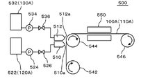
- FIG. 4 is a diagram for explaining an apparatus 500 for manufacturing a negative electrode sheet 100A.
- FIG. 5 is a diagram for explaining a process in which the negative electrode sheet 100A is manufactured by the apparatus 500 shown in FIG.
- the device 500 includes a first discharge head 510, a second discharge head 512, a first tank 522, a first pump 524, a first valve 526, a second tank 532, a second pump 534, and a second valve 536. It includes a first transfer roller 542, a second transfer roller 544, a third transfer roller 546, and a dryer 550.
- the first discharge head 510 and the second discharge head 512 have a discharge port 510a and a discharge port 512a, respectively.
- the first discharge head 510 and the second discharge head 512 may be configured by one discharge head.
- One discharge head may have at least a discharge port 510a and a discharge port 512a.
- the first transfer roller 542, the second transfer roller 544, and the third transfer roller 546 are in the direction of the arrows attached to the first transfer roller 542, the second transfer roller 544, and the third transfer roller 546 (clockwise). It is rotating around). Therefore, the negative electrode current collector sheet 110A is fed from the lower side to the upper side from the first transport roller 542 to the second transport roller 544, and is fed from the left side to the right side from the second transport roller 544 to the third transport roller 546. Has been done.
- This method (A) A step of applying a negative electrode active material slurry (hereinafter, also referred to as a first slurry 120A) containing at least a negative electrode active material and a binder on the first surface 112 of the negative electrode electrode sheet 100A. (B) A step of applying an insulating layer slurry (hereinafter, also referred to as a second slurry 130A) containing at least an insulating substance and a binder on the surface 122 of the negative electrode active material layer 120 (first slurry 120A). When, (C) The steps of simultaneously drying the first slurry 120A and the second slurry 130A applied in the above step (A) and the above step (B) are included in at least this order.
- a negative electrode active material slurry hereinafter, also referred to as a first slurry 120A
- an insulating layer slurry hereinafter, also referred to as a second slurry 130A
- the first slurry 120A wets and spreads along the first surface 112 of the negative electrode current collector sheet 110A and is applied to the first surface 112 of the negative electrode current collector sheet 110A (FIG. 5 (FIG. 5). a) See).
- the second slurry 130A wets and spreads along the surface 122 of the negative electrode active material layer 120 formed by the first slurry 120A applied in the step (A), and spreads wet and spreads along the surface 122 of the negative electrode active material layer 120. Is applied to the surface 122 of (see FIG. 5 (b)).
- a mixed layer 320 of the negative electrode active material layer 120 (first slurry 120A) and the insulating layer 300 (second slurry 130A) is located at the interface between the negative electrode active material layer 120 and the insulating layer 300. Is formed.
- the thickness of the mixed layer 320 is thinner than the thickness of the negative electrode active material layer 120.
- the first slurry 120A is housed in the first tank 522.
- the second slurry 130A is housed in the second tank 532.
- the first slurry 120A housed in the first tank 522 is supplied to the discharge head 510 via the first pump 524 and the first valve 526.
- the second slurry 130A housed in the second tank 532 is supplied to the discharge head 510 via the second pump 534 and the second valve 536.
- the first slurry 120A supplied to the discharge head 510 is discharged from the discharge port 510a of the first discharge head 510 toward the first surface 112 of the negative electrode current collector sheet 110A.
- the pressure of the first slurry 120A discharged to the first surface 112 of the negative electrode current collector sheet 110A is adjusted by, for example, the first pump 524.
- the flow rate of the first slurry 120A discharged to the first surface 112 of the negative electrode current collector sheet 110A is adjusted by, for example, the first valve 526.
- the second slurry 130A supplied to the discharge head 510 is discharged from the discharge port 512a of the second discharge head 512 toward the first surface 112 of the negative electrode current collector sheet 110A.
- the pressure of the second slurry 130A discharged to the first surface 112 of the negative electrode current collector sheet 110A is adjusted by, for example, the second pump 534.
- the flow rate of the second slurry 130A discharged to the first surface 112 of the negative electrode current collector sheet 110A is adjusted by, for example, the second valve 536.
- the first slurry 120A and the second slurry 130A are sequentially discharged from the discharge port 510a of the first discharge head 510 and the discharge port 512a of the second discharge head 512, respectively. Therefore, the second slurry 130A further wets and spreads along the upper surface 122 of the negative electrode active material layer 120 formed by the first slurry 120A that wets and spreads along the first surface 112.
- the first slurry 120A and the second slurry 130A are continuously applied in the direction in which the negative electrode current collector sheet 110A is conveyed. Therefore, the first slurry 120A and the second slurry 130A applied to the negative electrode current collector sheet 110A are continuously stretched along the direction in which the negative electrode current collector sheet 110A is conveyed.
- At least the discharge port 510a of the first discharge head 510 and the discharge port 512a of the second discharge head 512 are provided so as to be aligned in the direction in which the negative electrode current collector sheet 110A is conveyed.
- the first slurry 120A is discharged from the discharge port 510a of the first discharge head 510
- the second slurry 130A is discharged from the discharge port 512a of the second discharge head 512.
- the distance between the discharge port 510a of the first discharge head 510 and the discharge port 512a of the second discharge head 512 can be appropriately set.
- the first slurry 120A contains a material to be the negative electrode active material layer 120 and a solvent.
- the solvent contained in the first slurry 120A is, for example, water.
- the second slurry 130A contains a material to be the insulating layer 300 and a solvent.
- the solvent contained in the second slurry 130A is, for example, water.
- the solid content concentration of the first slurry 120A is 40% or more and 80% or less.
- the solid content concentration of the second slurry 130A is 20% or more and 80% or less.
- the negative electrode current collector sheet 110A is sent to the dryer 550.
- the first slurry 120A and the second slurry 130A are dried by the dryer 550.
- the first slurry 120A and the second slurry 130A are formed on the negative electrode active material layer 120 and the insulating layer 300, respectively, by drying the dryer 550.
- the negative electrode active material layer 120 (first slurry) is located at the interface between the negative electrode active material layer 120 formed by the first slurry 120A and the insulating layer 300 formed by the second slurry 130A.
- a mixed layer 320 of the insulating layer 300 (second slurry 130A) and the insulating layer 300 (120A) is formed.
- the thickness of the mixed layer 320 is thinner than that of the negative electrode active material layer 120.
- the thickness of the mixed layer 320 is evaluated by the following method.
- the direction from the surface 122 of the negative electrode active material layer 120 toward the current collector 110 is the Z direction.
- a scanning electron microscope (SEM) is used to analyze an SEM image obtained by photographing a cross section of the negative electrode electrode 100.
- element mapping is performed using an energy dispersive X-ray spectroscopy (EDX) method.
- EDX energy dispersive X-ray spectroscopy
- Z B be the average thickness of the negative electrode active material layer 120 in the Z direction. At this time, Z A / Z B is 11% or less.
- the maximum value Z A of Z-direction thickness is preferably at 35 ⁇ m or less, more preferably 25 ⁇ m or less.
- the negative electrode electrode 100 has an insulating material and a binder on the surface 122 of the negative electrode active material layer 120 formed on the first surface 112 of the sheet-shaped current collector 110. It has an insulating layer 300 including at least.
- the binder contained in the insulating layer 300 includes at least one selected from styrene-butadiene rubber and carboxymethyl cellulose and a salt thereof, and the negative electrode active material layer 120 contains at least one.
- the binder contained may be at least one selected from polyacrylic acid and salts thereof. This makes it possible to manufacture the negative electrode 100 in which the negative electrode active material layer 120 and the insulating layer 300 are not excessively mixed.
- the insulating layer 300 is applied after the negative electrode active material layer 120 is coated, dried, and pressed, a thin mixed layer is formed between the negative electrode active material layer 120 and the insulating layer 300. 320 is not formed. Therefore, the peel strength between the negative electrode active material layer 120 and the insulating layer 300 is low, and similarly, it cannot be said that the insulating function between the positive electrode and the negative electrode is sufficient.
- the insulating layer 300 cannot be uniformly applied due to the unevenness and wrinkles of the pressed surface to be coated, and the alliance cannot be obtained due to the gloss of the surface to be coated. Therefore, the negative electrode active material layer 120 may not be completely covered by the insulating layer 300, or the insulating layer 300 may be coated on a portion where the insulating layer 300 should not be coated.
- the solvents used for the slurry of the negative electrode active material layer 120 and the insulating layer 300 are not the same, the affinity Is low, so the mixed layer 320 is not formed.
- the negative electrode current collector sheet 110A is mounted on the negative electrode current collector sheet 110A.
- step (C) A step of simultaneously drying the slurry applied in the step (A) and the step (B), and Is included at least in this order, so that the above-mentioned problems of the sequential coating and drying method are solved, and when the insulating layer 300 is formed on the negative electrode active material layer 120, between the negative electrode active material layer 120 and the insulating layer 300. It is possible to improve the adhesion of the insulating layer 300 and prevent the insulating performance of the insulating layer 300 from deteriorating.
- the simultaneous drying method even if the solvent used for the slurry of the negative electrode active material layer 120 and the insulating layer 300 is the same, if the combination of the binder used for each slurry is not appropriate, the insulating layer slurry (second slurry) There was excessive penetration of 130A) into the negative electrode active material layer 120.
- the manufacturing method of the present embodiment by using the binder used for each slurry in an appropriate combination, it is possible to prevent the insulating layer slurry (second slurry 130A) from excessively permeating into the negative electrode active material layer 120. , It is possible to prevent the insulation performance of the insulating layer from deteriorating.
- the thickness of the mixed layer 320 of the negative electrode active material layer 120 and the insulating layer 300 formed at the interface between the negative electrode active material layer 120 and the insulating layer 300 is the thickness of the negative electrode active material layer 120. Thinner than thick.
- the active material is not exposed on the surface of the insulating layer 300, and the insulating function is impaired. There is no such thing. As a result, the insulating functions of the positive electrode and the negative electrode of the lithium ion secondary battery can be appropriately maintained.
- the maximum depth Z A at which the insulating material is detected in the negative electrode active material layer 120 is Z A / Z B , where Z B is the average thickness of the negative electrode active material layer in the Z direction. Is 11% or less, so that the diffusion of the insulating substance into the negative electrode active material layer 120 is not excessive.
- the particle size of the insulating substance is limited to 0.2 ⁇ m or more and 0.8 ⁇ m or less. This can prevent the problem that the insulating substance is not covered if the particle size is too small, and the problem that the number of particles is smaller than the film thickness and the insulating property is lowered if the particle size is too large. That is, it promotes a suitable coating, and since the particles are contained in an appropriate ratio with respect to the film thickness, it is possible to maintain an appropriate insulating property.
- the amount of the binder (binder) of the insulating layer 300 by limiting the amount of the binder (binder) of the insulating layer 300, it is possible to solve the problem that the adhesion deteriorates if the amount of the binder is too small. Further, when the amount of the binder is large, the gap in the insulating layer becomes small, the movement of the lithium salt between the positive and negative electrodes is hindered, and the problem that the resistance of the battery increases can be solved.
- the binder (binder) of the negative electrode active material layer 120 by limiting the amount of the binder (binder) of the negative electrode active material layer 120, a sufficient amount of the negative electrode active material is secured, and there is no excessive binder having high electrical resistance. The effect that a high-capacity and high-output electrode can be obtained can be obtained.
- the separator arranged between the positive electrode 200 and the negative electrode 100 becomes unnecessary.
- the lithium ion secondary battery can be made thinner, and a short circuit between the positive electrode and the negative electrode of the lithium ion secondary battery can be prevented.
- the negative electrode active material slurry (first slurry 120A) containing at least the negative electrode active material, the binder, and the solid electrolyte is applied.
- the solid electrolyte is, for example, Li 7 La 3 Zr 2 O 12 (LLZ).
- a high resistance layer slurry (second slurry 130A) containing at least a solid electrolyte and a binder is applied on the surface 122 of the negative electrode active material layer 120.
- the solid electrolyte is, for example, Li 7 La 3 Zr 2 O 12 (LLZ).
- the slurry applied in the step (A) and the step (B) is dried at the same time.
- the insulating substance contained in the insulating layer 300 is, for example, aluminum oxide (for example, ⁇ -alumina), silica, acrylic resin, magnesia, calcia, titania, zirconia, boehmite, and the like. And at least one selected from magnesium hydroxide.
- the high resistance layer is a solid electrolyte and does not necessarily have to contain the insulating substance contained in the above-mentioned insulating layer 300. That is, in the case of an all-solid-state battery, the high resistance layer (high resistance layer slurry) may contain at least a solid electrolyte.
- Table 1 shows the production conditions and evaluation results of the negative electrode 100 of Examples 1 to 11. Details of the sample production conditions will be described below.
- the negative electrode active material constituting the negative electrode active material layer 120 natural graphite coated with amorphous graphite manufactured by Hitachi Kasei Co., Ltd. was used.
- the negative electrode active material layer 120 contained a conductive auxiliary agent, and carbon black was used as the conductive auxiliary agent.
- carbon black C65 was set to 0.4% by weight based on the total weight of the solid material constituting the negative electrode active material layer 120.
- binder (binder) constituting the negative electrode active material layer 120 Aqua Charge manufactured by Sumitomo Seika Chemical Co., Ltd. was used as polyacrylic acid (PAA).
- any one of alumina, an acrylic resin (PolyMethylMethacrylate resin (PMMA)), and silica was used.
- alumina Alumina AKP-3000 manufactured by Sumitomo Chemical Co., Ltd. was used.
- acrylic resin (PMMA) a part number (grade) MX-80H3wT (average particle diameter 0.8 ⁇ m, degree of cross-linking: high) of the cross-linked acrylic monodisperse particle MX series manufactured by Soken Chemical Co., Ltd. was used.
- silica SFP-20M (0.3 ⁇ m) or SFP-30M (0.6 ⁇ m) of Super Fine Powder (submicron silica) manufactured by Denka Co., Ltd. was used.
- binder that constitutes the insulating layer 300 a mixture of sodium carboxymethyl cellulose (CMC-Na: Sodium Carboxymethyl Cellulose) and styrene butadiene rubber (SBR: Styrene-Butadiene Rubber) was used.
- CMC MAC-350HC of MAC series of Sunrose (registered trademark) manufactured by Nippon Paper Industries Co., Ltd. was used.
- SBR BM-451B manufactured by Nippon Zeon Corporation was used.
- the viscosity of each slurry was 8000 ⁇ 2000 mPa ⁇ s (conditions: B-type viscometer, 20 ° C., shear rate 2.04s-1). Simultaneous coating was performed using the two first discharge heads 510 and the second discharge head 512 of FIG. Simultaneous coating will be described later.
- the unit weight, the anode active material layer 120 is 11 mg / cm 2
- the insulating layer 300 was 2 mg / cm 2.
- some Examples and Comparative Examples prepared samples in which the basis weight of the insulating layer 300 was changed.
- the negative electrode 100 produced by the following method was evaluated. (1) Continuity confirmation by tester Samples of Examples 1 to 11 and Comparative Examples 1 to 14 were performed. The results are shown in Tables 1 and 2. (2) Photographs of the electrode surface were taken and the whiteness was measured. The samples of Example 1, Comparative Examples 1, 5 and 9 were taken. The results will be described later.
- the slurry applied in the following steps (A) and (B) was dried at the same time.
- the coating steps (A) and (B) are sequentially performed, and drying the two types of slurry at the same time is called simultaneous coating.
- the sequential coating after the following step (A), the slurry applied in the step (A) was dried, and then the following step (B) was performed to dry the slurry applied in the step (B).
- B) Insulation containing at least an insulating material and a binder on the surface of the negative electrode active material layer Process of applying layer slurry
- Continuity confirmation by tester was a digital multimeter (CDM-2000) manufactured by Custom Co., Ltd. The resistance range was measured at 30 M ⁇ .
- the negative electrode electrode sheet 100A includes a copper foil (current collector sheet), a negative electrode active material layer 120, and an insulating layer 300.
- the continuity confirmation method was set to "insulation” if the measurement limit (open range) was applied by applying the tip of the test lead of the tester from the front and back surfaces of the 10 cm square sample. Continuity was confirmed for 10 samples, and the ratio of the number of insulated samples (the number of samples for which continuity was not obtained) was calculated. If all 10 are insulated, it is 100%.
- the insulation rate was 100% in all of Examples 1 to 11. In other words, in any of Examples 1 to 11, it is shown that good insulation was obtained in all 10 samples.
- the binder contained in the insulating layer 300 includes at least one selected from styrene-butadiene rubber and carboxymethyl cellulose and a salt thereof, and the negative electrode active material layer 120.
- the binder (binder) contained in was at least one selected from polyacrylic acid and salts thereof.
- the binder contained in the insulating layer 300 is a mixture of CMC and SBR, and the binder contained in the negative electrode active material layer 120 is a binder. PAA was used.
- the D50 particle size in which the cumulative volume in the particle size distribution of the insulating substance constituting the insulating layer 300 is 50% is in the range of 0.2 ⁇ m or more and 0.8 ⁇ m or less.
- Example 10 is 0.3 ⁇ m (small)
- Example 11 is 0.6 ⁇ m (large)
- Examples 1 to 8 are 0.7 ⁇ m (large)
- Example 9 is 0.8 ⁇ m (large). I used the one. No effect of the D50 particle size of the insulating material on the insulation rate was observed.
- the weight of SBR contained in the insulating layer 300 was set to 3% by weight or more and 6% by weight or less in the total weight of the solid materials constituting the insulating layer 300.
- Examples 1 to 3, 6 to 8 and 11 were 3% by weight
- Examples 4 to 5 and 10 were 4% by weight
- Example 9 was 6% by weight.
- the total content of CMC and SBR of the binder of the insulating layer 300 is 7% by weight in Examples 1 to 2, 6 to 8 and 10, 6% by weight in Examples 3 and 11, and 9% by weight in Example 4.
- Example 5 10% by weight was used, and in Example 9, 12% by weight was used. No effect on the insulation rate was observed due to the total contents of CMC and SBR of the binder of the insulating layer 300.
- Example 1 In each of Examples 1 to 11, of the total weight of the solid material constituting the negative electrode active material layer 120, the polyacrylic acid contained in the negative electrode active material layer 120 and the binder of the salt thereof, the polyacrylic acid. And the total weight of the salt was 3% by weight or more and 6% by weight or less. Specifically, the weight of the PAA of the binder was set to 3% by weight in Examples 1 to 6 and 9 to 11, 4% by weight in Example 7, and 6% by weight in Example 8. This is included in the range of 3% by weight or more and 6% by weight or less. No effect on the insulation rate was observed due to the PAA content of the binder of the negative electrode active material layer 120.
- the insulating substance constituting the insulating layer 300 is at least one selected from alumina, silica, acrylic resin, magnesia, calcia, titania, zirconia, boehmite, and magnesium hydroxide. It was included. Specifically, Alumina was used in Examples 1 to 8, acrylic resin was used in Example 9, and silica was used in Examples 10 to 11.
- Example 2 was a 2.6 mg / cm 2 larger than the 2.0 mg / cm 2 of basis weight of the insulating layer 300 in Example 1. No effect on the insulation rate was observed due to the basis weight of the insulating layer 300.
- silica was added to the negative electrode active material, and the PAA content of the binder was changed.
- silica was 2.9% by weight (small)
- PAA was 3% by weight
- silica was 9.6% by weight (small) in the total weight of the solid material constituting the negative electrode active material layer 120.
- PAA was 4% by weight
- silica was 37.4% by weight (large)
- PAA was 6% by weight in Example 8.
- the content of PAA was 3% by weight or more and 6% by weight or less.
- the addition of silica to the negative electrode active material did not affect the insulation rate.
- Table 2 shows the production conditions and evaluation results of the negative electrode 100 of Comparative Examples 1 to 14.
- the binder contained in the insulating layer 300 did not contain at least one selected from styrene-butadiene rubber and carboxymethyl cellulose and a salt thereof, and PAA was used. PAA was used as the binder contained in the negative electrode active material layer 120.
- the basis weight of the insulating layer 300 was 2.6 mg / cm 2 , which was larger than that of Comparative Example 1.
- the mixing ratio of PAA of the binder (binder) contained in the insulating layer 300 was made larger than that of Comparative Example 1.
- Comparative Example 4 silica was added to the graphite of Example 1 as the negative electrode active material, and the weight of the PAA of the binder contained in the negative electrode active material layer 120 out of the total weight of the solid materials constituting the negative electrode active material layer 120. was 4% by weight, which was higher than that of Comparative Example 1.
- Comparative Examples 1 to 4 show that insulation was obtained in 2 out of 10 samples, but good insulation was not obtained in 8 of them.
- the binder contained in the insulating layer 300 does not contain at least one selected from styrene-butadiene rubber and carboxymethyl cellulose and a salt thereof, and has good insulating properties in Comparative Examples 1 to 4. Was not obtained.
- the negative electrode active material Even if the amount of the insulating layer 300 is increased (Comparative Example 2) or the mixing ratio of PAA of the binder (binder) contained in the insulating layer 300 is increased (Comparative Example 3), the negative electrode active material. Even if silica was added to (Comparative Example 4) or the mixing ratio of PAA in the binder of the negative electrode active material layer 120 was increased (Comparative Example 4), the insulating property was 20% and was not affected by these conditions. ..
- Comparative Examples 5 to 8 CMC and SBR, which are not at least one selected from polyacrylic acid and salts thereof, were used as the binder contained in the negative electrode active material layer 120.
- the basis weight of the insulating layer 300 was 2.6 mg / cm 2 , which was larger than that of Comparative Example 5.
- the mixing ratio of CMC and SBR of the binder of the negative electrode active material layer 120 was made larger than that of Comparative Example 5.
- the total weight of the binder CMC and SBR contained in the negative electrode active material layer 120 was 4% by weight, which was larger than that of Comparative Example 5 among the total weight of the solid material constituting the negative electrode active material layer 120.
- Comparative Example 8 silica is added to the graphite of Comparative Example 5 as the negative electrode active material, and the weight of the PAA of the binder contained in the negative electrode active material layer 120 out of the total weight of the solid material constituting the negative electrode active material layer 120. was 4% by weight, which was higher than that of Comparative Example 5.
- Comparative Examples 5 to 8 show that good insulation was not obtained for all 10 samples.
- the binder contained in the negative electrode active material layer is not at least one selected from polyacrylic acid and a salt thereof, and the binder contained in the insulating layer 300 is styrene.
- Comparative Examples 5 to 8 containing at least one selected from butadiene rubber and carboxymethyl cellulose and a salt thereof good insulating properties were not obtained.
- Comparative Examples 9 to 11 CMC and SBR were used for the binders of both the negative electrode active material layer 120 and the insulating layer 300.
- the basis weight of the insulating layer 300 was 2.6 mg / cm 2 , which was larger than that of Comparative Example 9.
- the mixing ratio of CMC and SBR of the binder of the negative electrode active material layer 120 was made larger than that of Comparative Example 9.
- Comparative Examples 9 to 11 show that good insulation was not obtained for all 10 samples.
- the binder contained in the negative electrode active material layer 120 did not have good insulating properties in Comparative Examples 9 to 11, which are not at least one selected from polyacrylic acid and salts thereof.
- the insulating property is 0%. , Was not affected by these conditions.
- the insulating substance constituting the insulating layer 300 was an acrylic resin.
- both the binder of the negative electrode active material layer 120 and the insulating layer 300 are PAA
- Comparative Example 13 the binder of the negative electrode active material layer 120 is CMC and SBR
- the binder of the insulating layer 300 is PAA
- Comparative Example 14 is.
- the negative electrode active material layer 120 and the insulating layer 300 binder were both CMC and SBR.
- the insulation rate was 10%, and the insulation rate of Comparative Examples 13 and 14 was 0%. That is, even if an acrylic resin is used for the insulating layer 300, the binder contained in the negative electrode active material layer is not at least one selected from polyacrylic acid and a salt thereof, and is contained in the insulating layer 300. In Comparative Examples 5 to 8 in which the binder (binder) contained at least one selected from styrene-butadiene rubber, carboxymethyl cellulose and a salt thereof, good insulating properties could not be obtained.
- the whiteness of the negative electrode active material layer 120 alone is 11.7, and the whiteness of the insulating layer 300 alone is 79.7. That is, in Comparative Example 5, it can be seen that the insulating layer 300 has substantially penetrated into the negative electrode active material layer 120 and has substantially the same whiteness as in the case of only the negative electrode active material layer 120. In Comparative Example 5, the insulation rate is also 0%.
- Comparative Example 1 and Comparative Example 9 it can be seen that a certain degree of the insulating layer 300 permeates the negative electrode active material layer 120, and the value is lower than the whiteness in the case of only the insulating layer 300. In Comparative Example 1 and Comparative Example 9, the insulation rate is as low as 0 to 20%.
- Example 1 the whiteness was slightly lower than that of the case where only the insulating layer 300 was used, and the insulation rate was 100%. That is, it can be seen that the insulating layer 300 permeates the negative electrode active material layer 120 by a certain amount while maintaining the insulating property.
- FIGS. 6 and 7 show the results of cross-sections of the samples of Example 1, Comparative Examples 1, 5, and 9.
- the SEM image and the element mapping image using the EDX method are arranged in the order of left and right.
- the upper image of FIG. 6 is the sample of Example 1
- the lower image of FIG. 6 is the sample of Comparative Example 9
- the upper image of FIG. 7 is the sample of Comparative Example 1
- the lower image of FIG. 7 is the sample of Comparative Example 1.
- the results of the sample of Comparative Example 5 are shown.
- the uppermost layer is the insulating layer 300
- the lowermost layer is the negative electrode current collector 110
- the center is the negative electrode active material layer 120.
- the negative electrode of the second slurry 130A constituting the insulating layer 300 at the interface between the insulating layer 300 and the negative electrode active material layer 120 of the sample of Example 1 It can be seen that the penetration into the active material layer 120 is the least.
- a mixed layer 320 of the negative electrode active material layer 120 and the insulating layer 300 which is thinner than the thickness of the negative electrode active material layer 120, is formed. ..
- Z A / Z B was 6.1%, which was 11% or less.
- Z A was 6.3 ⁇ m.
- the insulation rate of the sample of Example 1 was 100%.
- the second slurry 130A constituting the insulating layer 300 It can be seen that the penetration into the negative electrode active material layer 120 is the largest.
- the above-mentioned Z A / Z B was 79%, which was 11% or more.
- the insulation rate of the sample of Comparative Example 9 was 0%.
- the sample of Comparative Example 1 (upper side of FIG. 7) has the insulating layer 300 and the negative electrode active material layer more than the sample of Comparative Example 5 (lower side of FIG. 7). It can be seen that at the interface between 120, the penetration of the second slurry 130A constituting the insulating layer 300 into the negative electrode active material layer 120 is small.
- the above-mentioned Z A / Z B of the samples of Comparative Example 1 and Comparative Example 5 were 44% and 36%, respectively, and both were 11% or more.
- the insulation rate of the sample of Comparative Example 1 is 20%, which is higher than the insulation rate of the sample of Comparative Example 5 of 0%.
- a negative electrode for a lithium ion secondary battery in which a negative electrode active material layer containing at least a negative electrode active material and a binder is formed.
- An insulating layer containing at least an insulating substance and a binder is further provided on the surface of the negative electrode active material layer.
- the binder contained in the insulating layer contains at least styrene-butadiene rubber and at least one selected from carboxymethyl cellulose and a salt thereof.
- the binder contained in the negative electrode active material layer is a negative electrode for a lithium ion secondary battery, which is at least one selected from polyacrylic acid and a salt thereof. 2.
- the negative active not detected from material, said insulation and Z a maximum value of Z direction elements to be detected is detected from the material, the average thickness of the Z direction of the negative electrode active material layer when was the Z B, Z a / Z B is less than 11%, 1. 1. Or 2. Negative electrode for lithium ion secondary battery according to. 4. Maximum value Z A of the thickness of the Z-direction is 35 ⁇ m or less, 3. 3. Negative electrode for lithium ion secondary battery according to. 5. The D50 particle size at which the cumulative volume in the particle size distribution of the insulating substance is 50% is 0.2 ⁇ m or more and 0.8 ⁇ m or less. 1. 1. From 4. The negative electrode for the lithium ion secondary battery according to any one of the above. 6.
- the weight of the styrene-butadiene rubber contained in the insulating layer is 3% by weight or more and 6% by weight or less. 1. 1. From 5.
- the total weight of polyacrylic acid and its salt among the binders of polyacrylic acid and its salt contained in the negative electrode active material layer is 3 weight. % Or more and 6% by weight or less, 1. 1. From 6.
- the insulating material comprises at least one selected from alumina, silica, acrylic resin, magnesia, calcia, titania, zirconia, boehmite, and magnesium hydroxide.
- alumina silica
- acrylic resin magnesia
- calcia calcia
- titania zirconia
- boehmite magnesium hydroxide.
- a lithium ion secondary battery including a positive electrode having a positive electrode active material layer formed on a current collector, a negative electrode, and an electrolyte, wherein the negative electrode is 1. From 8. The negative electrode according to any one of the above. Lithium-ion secondary battery. 10. The insulating layer is formed on at least the entire surface of the negative electrode active material layer of the negative electrode facing the region where the active material layer of the positive electrode is formed. 9. Lithium ion secondary battery described in. 11. A separator different from the insulating layer formed on the negative electrode active material layer of the negative electrode is not arranged between the positive electrode and the negative electrode. 9. Or 10. Lithium ion secondary battery described in.
- a step of applying a negative electrode active material slurry containing at least a negative electrode active material and a binder and
- B A step of applying an insulating layer slurry containing at least an insulating substance and a binder on the surface of the negative electrode active material slurry.
- C A step of simultaneously drying the slurry applied in the step (A) and the step (B), and A method for manufacturing a negative electrode for a lithium ion secondary battery, which comprises at least in this order.
- the binder contained in the insulating layer slurry contains at least styrene-butadiene rubber and at least one selected from carboxymethyl cellulose and a salt thereof.
- a method for manufacturing a negative electrode for a lithium ion secondary battery wherein the binder contained in the negative electrode active material slurry is at least one selected from polyacrylic acid and a salt thereof. 13.
- the negative electrode active material slurry containing at least the negative electrode active material and the binder, and the insulating layer slurry containing at least the insulating material and the binder are continuous in the direction in which the current collector sheet is continuously conveyed.
- a method for manufacturing a negative electrode sheet for a lithium ion secondary battery which is specifically applied. 14.
- the negative electrode active material slurry is discharged from the first discharge port, and the insulating layer is used. Discharge the slurry from the second discharge port.
- the solid content concentration of the negative electrode active material slurry is 40% or more and 80% or less, and the solid content concentration of the insulating layer slurry is 20% or more and 80% or less. 13.
- the viscosity of the negative electrode active material slurry at a shear rate of 2.04s-1 at 20 ° C. by a B-type viscometer is 6 Pa ⁇ S or more and 10 Pa ⁇ S or less, and at 20 ° C. by a B-type viscometer of the insulating layer slurry.
- the viscosity at a shear rate of 2.04s-1 is 6 Pa ⁇ S or more and 10 Pa ⁇ S or less.
- the D50 particle diameter at which the cumulative volume in the particle size distribution of the insulating substance contained in the insulating layer slurry is 50% is 0.2 ⁇ m or more and 0.8 ⁇ m or less. 13.
- the polyacrylic acid and the total weight of the salt is 3% by weight or more and 6% by weight or less. 13. From 18. The method for manufacturing a negative electrode sheet for a lithium ion secondary battery according to any one of the above. 20.
- the insulating substance contains at least one selected from alumina, silica, acrylic resin, magnesia, calcia, titania, zirconia, boehmite, and magnesium hydroxide. 13. From 19. The method for manufacturing a negative electrode sheet for a lithium ion secondary battery according to any one of the above.
- a negative electrode for a lithium ion secondary battery in which a negative electrode active material layer containing at least a negative electrode active material and a binder is formed.
- a high resistance layer containing at least a solid electrolyte and a binder is further provided on the surface of the negative electrode active material layer.
- the binder contained in the high resistance layer contains at least styrene-butadiene rubber and at least one selected from carboxymethyl cellulose and a salt thereof.
- the binder contained in the negative electrode active material layer is a negative electrode for an all-solid-state lithium ion secondary battery, which is at least one selected from polyacrylic acid and a salt thereof. 22.
- Negative electrode for all-solid-state lithium-ion secondary battery according to. 23. When elemental mapping is performed using the EDX method in the cross-sectional SEM image of the cross section of the negative electrode, the direction of the negative electrode active material layer from the surface of the negative electrode active material layer on the side not in contact with the current collector toward the current collector side.
- the maximum value in the Z direction in which elements that are not detected in the negative electrode active material and are detected in the solid electrolyte are detected is Z A
- the average thickness of the negative electrode active material layer in the Z direction is defined as Z A.
- Z B Z A / Z B is 11% or less.
- Negative electrode for all-solid-state lithium-ion secondary battery according to. 24 Maximum value Z A of the thickness of the Z-direction is 35 ⁇ m or less, 23.
- the D50 particle size at which the cumulative volume in the particle size distribution of the solid electrolyte is 50% is 0.2 ⁇ m or more and 0.8 ⁇ m or less. 21. From 24.
- the weight of the styrene-butadiene rubber contained in the high resistance layer is 3% by weight or more and 6% by weight or less. 21. From 25.
- the total weight of polyacrylic acid and its salt among the binders of polyacrylic acid and its salt contained in the negative electrode active material layer is 3 weight. % Or more and 6% by weight or less, 21. From 26.
- An all-solid-state lithium-ion secondary battery including a positive electrode having a positive electrode active material layer formed on a current collector, a negative electrode, and a solid electrolyte, wherein the negative electrode is 21. From 27. The negative electrode according to any one of the above. All-solid-state lithium-ion secondary battery.
- a step of applying a negative electrode active material slurry containing at least a negative electrode active material and a binder A step of applying a high resistance layer slurry containing at least a solid electrolyte and a binder on the surface of the negative electrode active material slurry.
- C A step of simultaneously drying the slurry applied in the step (A) and the step (B), and A method for manufacturing a negative electrode for an all-solid-state lithium-ion secondary battery, which comprises at least in this order.
- the binder contained in the high resistance layer slurry contains at least styrene-butadiene rubber and at least one selected from carboxymethyl cellulose and a salt thereof.
- a method for manufacturing a negative electrode for an all-solid-state lithium ion secondary battery wherein the binder contained in the negative electrode active material slurry is at least one selected from polyacrylic acid and a salt thereof.
- a method for manufacturing a negative electrode sheet for an all-solid-state lithium-ion secondary battery for manufacturing a negative electrode for an all-solid-state lithium-ion secondary battery by the manufacturing method described in 1.
- the negative electrode active material slurry containing at least the negative electrode active material and the binder, and the high resistance layer slurry containing at least the solid electrolyte and the binder are continuous in the direction in which the collector sheet is continuously conveyed.
- a method for manufacturing a negative electrode sheet for an all-solid-state lithium-ion secondary battery are continuous in the direction in which the collector sheet is continuously conveyed.
- Lithium ion secondary battery 12 Laminated body 150 1st lead 250 2nd lead 400 Exterior material 100 Negative electrode 100A Negative electrode electrode sheet 110 Negative electrode current collector 110A Negative electrode current collector sheet 112 1st surface 114 2nd surface 120 Negative electrode active material Layer 122 Surface 200 Positive Electrode 210 Positive Electrode Collector 212 Third Surface 214 Fourth Surface 220 Positive Active Material Layer 300 Insulation Layer 312 Fifth Surface 314 Sixth Surface 320 Mixed Layer 120A First Slurry 130A Second Slurry 500 Device 510 1 Discharge head 510a Discharge port 512 2nd discharge head 512a Discharge port 522 1st tank 524 1st pump 526 1st valve 532 2nd tank 534 2nd pump 536 2nd valve 542 1st transfer roller 544 2nd transfer roller 546 3 Conveying roller 550 dryer
Landscapes
- Chemical & Material Sciences (AREA)
- Chemical Kinetics & Catalysis (AREA)
- Electrochemistry (AREA)
- General Chemical & Material Sciences (AREA)
- Engineering & Computer Science (AREA)
- Manufacturing & Machinery (AREA)
- Materials Engineering (AREA)
- Inorganic Chemistry (AREA)
- Composite Materials (AREA)
- Ceramic Engineering (AREA)
- Physics & Mathematics (AREA)
- Condensed Matter Physics & Semiconductors (AREA)
- General Physics & Mathematics (AREA)
- Battery Electrode And Active Subsutance (AREA)
- Secondary Cells (AREA)
Priority Applications (3)
| Application Number | Priority Date | Filing Date | Title |
|---|---|---|---|
| US18/001,038 US20230223652A1 (en) | 2020-06-11 | 2021-06-09 | Negative electrode, lithium ion secondary battery, manufacturing method of negative electrode for lithium ion secondary battery, and manufacturing method of negative electrode sheet for lithium ion secondary battery |
| EP21822812.0A EP4167309A4 (en) | 2020-06-11 | 2021-06-09 | NEGATIVE ELECTRODE, LITHIUM ION SECONDARY BATTERY, PRODUCTION PROCESS FOR NEGATIVE ELECTRODE FOR LITHIUM ION SECONDARY BATTERY AND PRODUCTION PROCESS FOR NEGATIVE ELECTRODE FILM FOR LITHIUM ION SECONDARY BATTERY |
| CN202180041865.0A CN115715429A (zh) | 2020-06-11 | 2021-06-09 | 负极电极、锂离子二次电池、锂离子二次电池用负极电极的制造方法、以及锂离子二次电池用负极电极片的制造方法 |
Applications Claiming Priority (2)
| Application Number | Priority Date | Filing Date | Title |
|---|---|---|---|
| JP2020-101806 | 2020-06-11 | ||
| JP2020101806A JP7692684B2 (ja) | 2020-06-11 | 2020-06-11 | 負極電極、リチウムイオン二次電池、リチウムイオン二次電池用負極電極の製造方法、および、リチウムイオン二次電池用負極電極シートの製造方法 |
Publications (1)
| Publication Number | Publication Date |
|---|---|
| WO2021251432A1 true WO2021251432A1 (ja) | 2021-12-16 |
Family
ID=78846071
Family Applications (1)
| Application Number | Title | Priority Date | Filing Date |
|---|---|---|---|
| PCT/JP2021/021934 Ceased WO2021251432A1 (ja) | 2020-06-11 | 2021-06-09 | 負極電極、リチウムイオン二次電池、リチウムイオン二次電池用負極電極の製造方法、および、リチウムイオン二次電池用負極電極シートの製造方法 |
Country Status (5)
| Country | Link |
|---|---|
| US (1) | US20230223652A1 (https=) |
| EP (1) | EP4167309A4 (https=) |
| JP (2) | JP7692684B2 (https=) |
| CN (1) | CN115715429A (https=) |
| WO (1) | WO2021251432A1 (https=) |
Families Citing this family (4)
| Publication number | Priority date | Publication date | Assignee | Title |
|---|---|---|---|---|
| JP7852992B2 (ja) * | 2022-06-02 | 2026-04-28 | エルジー エナジー ソリューション リミテッド | 電極組立体およびその製造方法と、これを含むリチウム二次電池 |
| WO2024224859A1 (ja) * | 2023-04-28 | 2024-10-31 | ビークルエナジージャパン株式会社 | 電極及び電池 |
| KR102795203B1 (ko) | 2023-06-19 | 2025-04-17 | 주식회사 엘지에너지솔루션 | 내부 단락에 대한 안전성이 개선된 리튬 이차전지용 음극, 이를 포함하는 리튬 이차전지 및 이를 위한 리튬 이차전지 시스템 |
| CN222015467U (zh) * | 2023-11-22 | 2024-11-15 | 宁德时代新能源科技股份有限公司 | 电池单体、电池及用电装置 |
Citations (7)
| Publication number | Priority date | Publication date | Assignee | Title |
|---|---|---|---|---|
| JP2013114882A (ja) * | 2011-11-29 | 2013-06-10 | Nissan Motor Co Ltd | リチウムイオン二次電池 |
| JP2016170945A (ja) | 2015-03-12 | 2016-09-23 | 日立マクセル株式会社 | 非水二次電池 |
| JP2017123220A (ja) * | 2016-01-04 | 2017-07-13 | 信越化学工業株式会社 | 非水電解質二次電池用負極活物質、非水電解質二次電池用負極、及び非水電解質二次電池、並びに非水電解質二次電池用負極活物質の製造方法 |
| JP2017147148A (ja) | 2016-02-18 | 2017-08-24 | 積水化学工業株式会社 | リチウムイオン二次電池用電極の製造方法 |
| JP2017152122A (ja) * | 2016-02-23 | 2017-08-31 | Tdk株式会社 | リチウムイオン二次電池用負極活物質、リチウムイオン二次電池用負極およびリチウムイオン二次電池 |
| WO2019107033A1 (ja) * | 2017-11-29 | 2019-06-06 | パナソニックIpマネジメント株式会社 | リチウムイオン電池 |
| JP2020101806A (ja) | 2005-03-31 | 2020-07-02 | 株式会社半導体エネルギー研究所 | 表示装置 |
Family Cites Families (10)
| Publication number | Priority date | Publication date | Assignee | Title |
|---|---|---|---|---|
| JP4957680B2 (ja) * | 2008-08-26 | 2012-06-20 | ソニー株式会社 | 非水電解質二次電池用の多孔性保護膜層付き電極、及び非水電解質二次電池 |
| WO2015080305A1 (ko) * | 2013-11-27 | 2015-06-04 | 주식회사 엘지화학 | 전극조립체 및 이를 포함하는 전기화학소자 |
| CN110476280A (zh) * | 2017-03-24 | 2019-11-19 | 日产自动车株式会社 | 非水电解质二次电池用负极和使用了该负极的非水电解质二次电池 |
| CN108666525A (zh) * | 2017-04-01 | 2018-10-16 | 宁德时代新能源科技股份有限公司 | 一种负极极片,其制备方法及二次电池 |
| JPWO2018212274A1 (ja) * | 2017-05-18 | 2020-05-21 | 日本電気株式会社 | リチウムイオン二次電池 |
| JP7031249B2 (ja) * | 2017-11-24 | 2022-03-08 | 日本電気株式会社 | 二次電池用電極の製造方法および二次電池の製造方法 |
| US20210057732A1 (en) * | 2018-02-06 | 2021-02-25 | Sekisui Chemical Co., Ltd. | Lithium ion secondary battery electrode, production method for same, and lithium ion secondary battery |
| WO2019176393A1 (ja) * | 2018-03-12 | 2019-09-19 | 日本電気株式会社 | 二次電池用電極、該電極を用いた二次電池およびそれらの製造方法 |
| WO2020050285A1 (ja) * | 2018-09-05 | 2020-03-12 | 積水化学工業株式会社 | リチウムイオン二次電池、その製造方法、及びリチウムイオン二次電池用電極 |
| JP7226264B2 (ja) * | 2019-11-20 | 2023-02-21 | トヨタ自動車株式会社 | 全固体電池 |
-
2020
- 2020-06-11 JP JP2020101806A patent/JP7692684B2/ja active Active
-
2021
- 2021-06-09 US US18/001,038 patent/US20230223652A1/en active Pending
- 2021-06-09 WO PCT/JP2021/021934 patent/WO2021251432A1/ja not_active Ceased
- 2021-06-09 EP EP21822812.0A patent/EP4167309A4/en active Pending
- 2021-06-09 CN CN202180041865.0A patent/CN115715429A/zh active Pending
-
2025
- 2025-06-04 JP JP2025093627A patent/JP2025116228A/ja not_active Withdrawn
Patent Citations (7)
| Publication number | Priority date | Publication date | Assignee | Title |
|---|---|---|---|---|
| JP2020101806A (ja) | 2005-03-31 | 2020-07-02 | 株式会社半導体エネルギー研究所 | 表示装置 |
| JP2013114882A (ja) * | 2011-11-29 | 2013-06-10 | Nissan Motor Co Ltd | リチウムイオン二次電池 |
| JP2016170945A (ja) | 2015-03-12 | 2016-09-23 | 日立マクセル株式会社 | 非水二次電池 |
| JP2017123220A (ja) * | 2016-01-04 | 2017-07-13 | 信越化学工業株式会社 | 非水電解質二次電池用負極活物質、非水電解質二次電池用負極、及び非水電解質二次電池、並びに非水電解質二次電池用負極活物質の製造方法 |
| JP2017147148A (ja) | 2016-02-18 | 2017-08-24 | 積水化学工業株式会社 | リチウムイオン二次電池用電極の製造方法 |
| JP2017152122A (ja) * | 2016-02-23 | 2017-08-31 | Tdk株式会社 | リチウムイオン二次電池用負極活物質、リチウムイオン二次電池用負極およびリチウムイオン二次電池 |
| WO2019107033A1 (ja) * | 2017-11-29 | 2019-06-06 | パナソニックIpマネジメント株式会社 | リチウムイオン電池 |
Non-Patent Citations (1)
| Title |
|---|
| See also references of EP4167309A4 |
Also Published As
| Publication number | Publication date |
|---|---|
| CN115715429A (zh) | 2023-02-24 |
| EP4167309A4 (en) | 2024-03-20 |
| EP4167309A1 (en) | 2023-04-19 |
| JP2021197249A (ja) | 2021-12-27 |
| JP2025116228A (ja) | 2025-08-07 |
| US20230223652A1 (en) | 2023-07-13 |
| JP7692684B2 (ja) | 2025-06-16 |
Similar Documents
| Publication | Publication Date | Title |
|---|---|---|
| KR102764103B1 (ko) | 음극, 이의 제조방법 및 이를 포함하는 이차전지 | |
| KR102824105B1 (ko) | 이차전지 | |
| KR102900348B1 (ko) | 음극 및 이를 포함하는 이차전지 | |
| KR102703667B1 (ko) | 음극 및 이를 포함하는 이차전지 | |
| KR102825910B1 (ko) | 음극 및 이를 포함하는 이차전지 | |
| WO2021251432A1 (ja) | 負極電極、リチウムイオン二次電池、リチウムイオン二次電池用負極電極の製造方法、および、リチウムイオン二次電池用負極電極シートの製造方法 | |
| KR102909999B1 (ko) | 이차전지의 제조방법 | |
| KR102799193B1 (ko) | 복합 음극 활물질, 이의 제조방법, 이를 포함하는 음극 및 이차전지 | |
| KR102914058B1 (ko) | 음극 및 이를 포함하는 이차전지 | |
| JP7771378B2 (ja) | 負極およびそれを含む二次電池 | |
| JP2024543464A (ja) | 負極およびこれを含む二次電池 | |
| JP7681759B2 (ja) | 正極活物質、正極及びこれを含むリチウム二次電池 | |
| JP2024525949A (ja) | 負極及びこれを含む二次電池 | |
| JP2025513391A (ja) | 正極および前記正極を含む二次電池 | |
| KR102882672B1 (ko) | 이차전지의 제조방법 | |
| KR102766500B1 (ko) | 전지 시스템, 이의 사용방법, 및 이를 포함하는 전지 팩 | |
| KR102803278B1 (ko) | 음극 및 이를 포함하는 이차전지 | |
| CN120356901A (zh) | 正电极和包括该正电极的可再充电锂电池 | |
| US20260100371A1 (en) | Electrodes and rechargeable lithium batteries including the same | |
| JP7715451B2 (ja) | 電極および電極の製造方法 | |
| JP2021089826A (ja) | 正極電極、リチウムイオン二次電池及び正極電極シートの製造方法 | |
| JP7842142B2 (ja) | リチウム二次電池用正極およびこれを含むリチウム二次電池 | |
| JP2025139009A (ja) | リチウムイオン二次電池用正極、リチウムイオン二次電池および算出方法 | |
| JP2025139027A (ja) | リチウムイオン二次電池用正極、リチウムイオン二次電池および算出方法 | |
| JP2025139068A (ja) | リチウムイオン二次電池正極、リチウムイオン二次電池および算出方法 |
Legal Events
| Date | Code | Title | Description |
|---|---|---|---|
| 121 | Ep: the epo has been informed by wipo that ep was designated in this application |
Ref document number: 21822812 Country of ref document: EP Kind code of ref document: A1 |
|
| NENP | Non-entry into the national phase |
Ref country code: DE |
|
| ENP | Entry into the national phase |
Ref document number: 2021822812 Country of ref document: EP Effective date: 20230111 |