WO2021250794A1 - Dispositif de traitement d'informations biologiques, procédé de traitement d'informations biologiques et programme de traitement d'informations biologiques - Google Patents
Dispositif de traitement d'informations biologiques, procédé de traitement d'informations biologiques et programme de traitement d'informations biologiques Download PDFInfo
- Publication number
- WO2021250794A1 WO2021250794A1 PCT/JP2020/022760 JP2020022760W WO2021250794A1 WO 2021250794 A1 WO2021250794 A1 WO 2021250794A1 JP 2020022760 W JP2020022760 W JP 2020022760W WO 2021250794 A1 WO2021250794 A1 WO 2021250794A1
- Authority
- WO
- WIPO (PCT)
- Prior art keywords
- electrocardiogram
- wave
- measurement
- unit
- instantaneous
- Prior art date
Links
Images


Classifications
-
- A—HUMAN NECESSITIES
- A61—MEDICAL OR VETERINARY SCIENCE; HYGIENE
- A61B—DIAGNOSIS; SURGERY; IDENTIFICATION
- A61B5/00—Measuring for diagnostic purposes; Identification of persons
- A61B5/24—Detecting, measuring or recording bioelectric or biomagnetic signals of the body or parts thereof
- A61B5/316—Modalities, i.e. specific diagnostic methods
- A61B5/318—Heart-related electrical modalities, e.g. electrocardiography [ECG]
- A61B5/346—Analysis of electrocardiograms
Definitions
- One aspect of the present invention relates to a biometric information processing apparatus, a biometric information processing method, and a biometric information processing program.
- both autonomic nerves There are two autonomic nerves, the sympathetic nerve and the vagus nerve. Both autonomic nerves are widely distributed in each organ and control involuntary physical functions such as circulation and metabolism. In many cases, it is said that both autonomic nerves dominate one organ antagonistically.
- sympathetic nerve activity which is one of the autonomic nerve activities, is enhanced by stress stimuli such as mental arithmetic load.
- vagus nerve which is another autonomic nerve, is often understood in the same way as parasympathetic nerve activity because it is mainly responsible for parasympathetic nerve activity in each organ controlled by the nerve.
- the "vagus nerve” is the name of the Xth nerve, which is one of the cranial nerves, and refers to all the nerves from the brain to each organ. Therefore, the parasympathetic nerve activity in the target organ may be indicated by adding the name of the organ to be controlled (eg, cardiac vagus nerve).
- the heart is one of the organs controlled by the autonomic nerves.
- the heart is antagonized by the sympathetic and vagus nerves and is said to reflect the static balance of both autonomic nerve activities.
- RRI instantaneous heartbeat
- the R wave is one of the electrocardiographic waveforms obtained by the electrocardiogram measurement, and reflects the depolarizing activity of the heart.
- the low frequency component (hereinafter, also referred to as HRV LF ) when the instantaneous heartbeats at unequal intervals are analyzed by the frequency spectrum is interpreted as an index reflecting the sympathetic nerve activity and the cardiac vagus nerve activity. ..
- the high frequency component (hereinafter, also referred to as HRV HF ) is interpreted as an index reflecting the cardiac vagus nerve activity.
- a wearable device such as a Holter electrocardiograph.
- measurement abnormalities occur due to electrode abnormalities such as electrode deformation and displacement, or various factors such as body movement, sweating, and static electricity.
- This measurement abnormality can be confirmed on the electrocardiogram in the form of artifacts and noise.
- the duration of both noise and artifact changes depending on the duration of the measurement abnormality.
- the waveform observed as an artifact has a frequency characteristic very similar to that of the R wave, so it is very difficult to completely remove it by general filtering. Therefore, the algorithm that analyzes the electrocardiogram and extracts the R wave may mistakenly determine the artifact as the R wave and extract it.
- HRV LF and HRV HF reflect autonomic nervous activity only if all the data to be analyzed are normal instantaneous heartbeats.
- the normal state here means a state in which there is no abnormality in both the measurement target and the measuring instrument.
- the abnormality to be measured refers to the arrhythmia of the subject.
- the abnormality of the measuring instrument refers to the state in which the measurement abnormality has occurred on the electrocardiogram.
- An artifact that is one of the measurement abnormalities is misjudged as an R wave, and does not reflect the depolarizing activity of the heart at all due to its generation mechanism. Therefore, if at least one of the R waves constituting the instantaneous heartbeat to be analyzed is erroneously determined that the artifact is an R wave, neither HRV LF nor HRV HF can be said to reflect the autonomic nervous activity. ..
- Method 1 The measurement state of the instantaneous heartbeat is discriminated based on the potential amplitude information of each of the two R waves constituting the instantaneous heartbeat, and the instantaneous heartbeat that seems to be a measurement abnormality is excluded (see, for example, Non-Patent Document 1).
- Method 2 In order to detect measurement abnormalities (eg, myoelectric artifacts, etc.) that have potential amplitude characteristics equivalent to R waves, which is difficult to deal with by Method 1, the measurement state of the target ECG is evaluated in advance using statistical features. Then, the information is given to the R wave constituting the instantaneous heartbeat. Then, the reliability of the instantaneous heartbeat is evaluated based on the potential information of the two R waves constituting the instantaneous heartbeat, and the instantaneous heartbeat that seems to be a measurement abnormality is excluded (see, for example, Non-Patent Document 2).
- measurement abnormalities eg, myoelectric artifacts, etc.
- Kana Eguchi, et al. “RRI measurement reliability evaluation for wearable electrocardiographs using QRS complex potential characteristics”, Shingaku Giho Vol.116, No.412, pp.171-176, 2017 K.
- Eguchi, et.al “RR Interval Outlier Exclusion Method Based on Statistical ECG Values Targeting HRV Analysis Using Wearable ECG Devices”, Proceedings of the 40th Annual International Conference of the IEEE Engineering in pp. 5689-5692, 2018.
- the above method 1 overcomes the problem of general filtering by using the potential amplitude information of the R wave constituting the instantaneous heartbeat.
- the measurement abnormality that occurs in the electrocardiogram does not always have the potential amplitude characteristic different from that of the R wave.
- an R wave such as a myoelectric artifact in which the potential amplitude characteristic equivalent to that of the R wave is erroneously determined cannot be detected as an abnormality.
- the above method 2 uses statistical features for each arbitrary time length in order to detect measurement abnormalities (eg, myoelectric artifacts, etc.) having potential amplitude characteristics equivalent to R waves, which are difficult to deal with by method 1.
- measurement abnormalities eg, myoelectric artifacts, etc.
- the problem of the method 1 is overcome.
- the measurement state evaluation result based on the statistical feature amount to the entire electrocardiogram used for calculating the feature amount the R wave that can be measured normally may be mistakenly regarded as a measurement abnormality.
- the present invention has been made by paying attention to the above circumstances, and is intended to provide a technique for improving the accuracy of determining an abnormality in an instantaneous heartbeat.
- the biometric information device has an electrocardiogram acquisition unit that acquires an electrocardiogram of a subject, an R wave extraction unit that extracts an R wave from the electrocardiogram, and an R wave extraction unit that removes the R wave from the electrocardiogram.
- An R wave removing unit that calculates an R waveless ECG that does not include waves, a measurement abnormality signal component extraction unit that extracts measurement abnormality signal components from the R waveless ECG, and the subject's measurement abnormality signal component based on the measurement abnormality signal component. It is provided with a measurement state determination unit that determines the measurement state of the electrocardiogram and generates measurement state determination information including the determination result of the measurement state of the electrocardiogram.
- the accuracy of determining abnormalities in instantaneous heartbeat can be improved.
- FIG. 1 is a schematic diagram of a biometric information processing system according to an embodiment of the present invention.
- FIG. 2 is a diagram showing the relationship between the R wave and the instantaneous heartbeat (RRI) in the electrocardiogram according to the embodiment of the present invention.
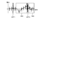
- FIG. 3 is a diagram showing an example of measurement abnormality in the electrocardiogram according to the embodiment of the present invention.
- FIG. 4 is a block diagram showing a software configuration of the biometric information processing apparatus according to the embodiment of the present invention.
- FIG. 5 is a flowchart showing a processing procedure and processing contents of the biometric information processing apparatus according to the embodiment of the present invention.
- FIG. 6 is a diagram illustrating an R wave removal process from the electrocardiogram according to the embodiment of the present invention.
- FIG. 7 is a diagram illustrating an extraction process of a measurement abnormality signal component according to the embodiment of the present invention.
- FIG. 1 is a schematic diagram of a biometric information processing system S.
- the biometric information processing system S includes an electrocardiogram measuring device 1 and a biometric information processing device 2.
- the electrocardiogram measuring device 1 measures the electrocardiogram of the subject and sends the measured electrocardiogram to the biometric information processing device 2.
- the electrocardiogram measuring device 1 measures an electrocardiogram with at least two electrodes.
- the electrocardiogram represents the circulatory system biological signals, eg, periodic signals synchronized with the contraction of the ventricles, over time.
- the electrocardiogram is sometimes called an electrocardiographic waveform. That is, the electrocardiogram contains time-series data capable of extracting an electrocardiogram corresponding to an R wave that reflects the depolarizing activity of the heart.
- the electrocardiogram measuring device 1 only needs to be able to measure the electrocardiogram equivalent to the R wave, and the realized form including the recording method of the measured electrocardiogram does not matter.
- the electrocardiogram measuring device 1 can be formed as a wearable device that can be attached to a subject such as a halter electrocardiograph and can record the measured electrocardiogram in the electrocardiogram measuring device 1.
- the electrocardiogram measuring device 1 records the electrocardiogram measured in its own device when the electrocardiogram measuring device 1 and the biometric information processing device 2 are configured separately, and the electrocardiogram measuring device 1 and the biometric information processing device 2 are separate from each other. Because it works.
- the biometric information processing apparatus 2 may acquire the electrocardiogram recorded in the electrocardiogram measuring device 1 in batch after the electrocardiogram measuring device 1 completes the measurement of the electrocardiogram, and may process the electrocardiogram in batch processing. .. Further, the electrocardiogram measuring device 1 may be integrally formed with the biometric information processing device 2, that is, the biometric information processing system S may be realized as one wearable device. When integrally formed in this way, the information processing apparatus 2 may process each process related to the electrocardiogram, which will be described later, in real time at the same time as the measurement of the electrocardiogram by the electrocardiogram measuring device 1. In this example, the electrocardiogram measuring device 1 does not have to record the electrocardiogram measured in its own device.
- the electrocardiogram measuring device 1 may be provided outside the biometric information processing system S.
- the heart rate variability analysis system S may capture the result of measuring the electrocardiogram of the subject from an external device corresponding to the electrocardiogram measuring device 1 into the biometric information processing device 2 via a network such as the Internet.
- the biometric information processing device 2 takes in the electrocardiogram measured by the electrocardiogram measuring device 1 and processes the electrocardiogram.
- the biometric information processing apparatus 2 can be realized by, for example, a dedicated hardware equipped with a microcomputer, a smartphone, a tablet terminal, a computer device such as a personal computer (PC).
- the biometric information processing device 2 includes a control unit 21, a communication I / F (interface) 22, and a storage unit 23.
- the control unit 21, the communication I / F 22, and the storage unit 23 are communicably connected to each other via a bus.
- the control unit 21 controls the biometric information processing device 2.
- the control unit 21 includes a hardware processor such as a central processing unit (CPU).
- the communication I / F 22 is an interface that enables communication with the electrocardiogram measuring device 1.
- the communication I / F 22 enables wired communication or wireless communication with the electrocardiogram measuring device 1 according to a predetermined standard.
- the storage unit 23 is a storage medium.
- the storage unit 23 includes a non-volatile memory such as an HDD (Hard Disk Drive) or SSD (Solid State Drive) that can be written and read at any time, and a non-volatile memory such as a ROM (Read Only Memory). It is configured in combination with a volatile memory such as RAM (Random Access Memory).
- the storage unit 23 includes a program storage area and a data storage area in the storage area.
- the program storage area stores application programs necessary for executing various processes, in addition to middleware such as an OS (Operating System).
- FIG. 2 is a diagram showing the relationship between the R wave and the instantaneous heartbeat in the electrocardiogram.
- the electrocardiogram is represented as a change in potential measured by the electrodes of at least two poles with time, and includes an R wave RW that reflects the depolarizing activity of the heart.
- the interval between two adjacent R-wave RWs is the instantaneous heart rate RRI.
- FIG. 3 is a diagram showing an example of measurement abnormality in an electrocardiogram. That is, the measurement abnormality can be confirmed on the electrocardiogram in the form of artifact ART1 and artifact ART2 or noise NOI as shown in FIG.
- the duration of the artifact ART1, the artifact ART2, and the noise NOI varies depending on the duration of the measurement abnormality.
- FIG. 4 is a block diagram showing a software configuration of the biometric information processing apparatus 2.
- the control unit 21 activates the electrocardiogram acquisition unit 211, the R wave extraction unit 212, the electrocardiogram measurement state evaluation unit 213, the instantaneous heart rate calculation unit 214, and the instantaneous heart rate evaluation unit. 215 and the instantaneous heartbeat abnormal value processing unit 216 are executed.
- the electrocardiogram acquisition unit 211 acquires the electrocardiogram of the subject. Specifically, the control unit 21 takes in the electrocardiogram from the electrocardiogram measuring device 1 via the communication I / F 22 and stores it in the storage unit 23. Further, the control unit 21 receives the electrocardiogram measured by the external device corresponding to the electrocardiogram measuring device 1 from the device or from the server or the like in which the measured electrocardiogram is stored by the communication I / F 22 via the network. It may be stored in the storage unit 23. Further, although not particularly shown, when the communication I / F 22 has a removable media (memory card) read function that can be attached to and detached from the biometric information processing apparatus 2, the control unit 21 measures the electrocardiogram. It is also possible to acquire an electrocardiogram measured by the device 1 or an external device corresponding to the electrocardiogram measuring device 1 via the storage medium thereof.
- the R wave extraction unit 212 extracts the R wave from the electrocardiogram acquired by the electrocardiogram acquisition unit 211.
- the R wave extraction unit 212 analyzes the electrocardiogram acquired by the electrocardiogram acquisition unit 211 stored in the storage unit 23, and extracts the R wave. In the embodiment, a specific method for extracting R waves does not matter.
- the R wave extraction unit 212 stores R wave related information in the R wave related information recording unit 231 for each extracted R wave.
- the R wave-related information is information related to the extracted R wave.
- the R wave related information includes R wave potential amplitude information based on the potential information.
- the potential information is information regarding the potential of the R wave
- the R wave potential amplitude information is information indicating the amplitude of the potential of the R wave.
- the R wave related information recording unit 231 is realized in a part of the data storage area of the storage unit 23.
- the R wave related information recording unit 231 records R wave related information for each R wave extracted by the R wave extraction unit 212.
- the R wave related information recording unit 231 records the R wave potential amplitude information based on the potential information.
- the R wave potential amplitude information is an example of information that can distinguish at least two types of R wave measurement states, a normal measurement state and an artifact.
- the R wave related information recording unit 231 uses information that can distinguish at least two types of normal measurement state and artifact as the R wave measurement state as the R wave related information to be recorded, but particularly specifies other information. do not do.
- the R wave-related information recording unit 231 may use the information regarding the time when the R wave extracted by the R wave extraction unit 212 appears as the R wave-related information to be recorded. Further, the specific recording format of the R wave related information is not specified. Recording of R wave related information by the R wave related information recording unit 231 is not essential, but the instantaneous heart rate evaluation unit 215 additionally uses the R wave potential amplitude information to evaluate the instantaneous heart rate based on the R wave measurement state. It is necessary for the case.
- the electrocardiogram measurement state evaluation unit 213 evaluates the measurement state of the electrocardiogram based on the electrocardiogram measured by the electrocardiogram measuring device 1.
- the electrocardiogram measurement state evaluation unit 213 includes an R wave removing unit 2131, a measurement abnormality signal component extraction unit 2132, and a measurement state determination unit 2133.
- the R wave removing unit 2131 removes the R wave acquired by the R wave extraction unit 212 from the electrocardiogram acquired by the electrocardiogram acquisition unit 211.
- the R wave removing unit 2131 calculates an electrocardiogram without an R wave that does not include the R wave.
- the measurement abnormality signal component extraction unit 2132 extracts the measurement abnormality signal component from the R waveless electrocardiogram calculated by the R wave removal unit 2131.
- the measurement state determination unit 2133 determines the measurement state of the subject's electrocardiogram based on the measurement abnormality signal component extracted by the measurement abnormality signal component extraction unit 2132.
- the measurement state determination unit 2133 generates measurement state determination information based on the determination.
- the measurement state determination information is information including the determination result of the measurement state of the electrocardiogram.
- the instantaneous heart rate calculation unit 214 calculates the instantaneous heart rate of the subject, which is the interval between two adjacent R waves in time series, using the R wave extracted by the R wave extraction unit 212. When necessary for subsequent processing, the instantaneous heart rate calculation unit 214 stores the calculated instantaneous heart rate information regarding the instantaneous heart rate in the instantaneous heart rate recording unit 232.
- the instantaneous heart rate recording unit 232 is realized in a part of the data storage area of the storage unit 23.
- the instantaneous heartbeat recording unit 232 records instantaneous heartbeat information for each instantaneous heartbeat calculated by the instantaneous heartbeat calculation unit 214.
- the specific recording format of the information in the instantaneous heart rate recording unit 232 is not particularly specified.
- the instantaneous heartbeat information is a matrix of instantaneous heartbeats, a data matrix composed of two elements, the time information of the first R wave (time information of instantaneous heartbeats) and the momentary heartbeats. Is possible.
- the instantaneous heart rate evaluation unit 215 generates instantaneous heart rate evaluation information using the instantaneous heart rate calculated by the instantaneous heart rate calculation unit 214 and the measurement state determination information generated by the measurement state determination unit 2133.
- the instantaneous heartbeat evaluation information is information indicating the evaluation of the instantaneous heartbeat.
- an evaluation standard other than the measurement state determination information may be used.
- the evaluation of the instantaneous heartbeat may take into account the R wave potential amplitude information.
- the instantaneous heart rate evaluation unit 215 generates the instantaneous heart rate evaluation information by further using the R wave potential amplitude information recorded in the R wave related information recording unit 231 in addition to the instantaneous heart rate and the measurement state determination information.
- the evaluation of the instantaneous heartbeat may take into account the time information of the instantaneous heartbeat.
- the instantaneous heart rate evaluation unit 215 generates the instantaneous heart rate evaluation information by further using the instantaneous heart rate time information recorded in the instantaneous heart rate recording unit 232 in addition to the instantaneous heart rate and the measurement state determination information.
- the evaluation of the instantaneous heartbeat may consider the R wave potential amplitude information and the time information of the instantaneous heartbeat.
- the instantaneous heartbeat evaluation unit 215 generates the instantaneous heartbeat evaluation information by further using the R wave potential amplitude information and the time information of the instantaneous heartbeat in addition to the instantaneous heartbeat and the measurement state determination information.
- the instantaneous heart rate abnormal value processing unit 216 processes the abnormal value of the instantaneous heart rate calculated by the instantaneous heart rate calculation unit 214 using the instantaneous heart rate evaluation information generated by the instantaneous heart rate evaluation unit 215.
- FIG. 5 is a flowchart showing a processing procedure and processing contents of the biometric information processing apparatus 2.
- a method will be described in which an artifact that is difficult to discriminate based on the potential amplitude characteristic of the R wave is targeted, and an artifact that is erroneously determined is excluded as an abnormal value.
- the processing procedure described below is only an example, and each processing may be changed as much as possible. Further, with respect to the processing procedure described below, steps can be omitted, replaced, and added as appropriate according to the embodiment.
- the electrocardiogram acquisition unit 211 acquires the electrocardiogram of the subject (step S1). In step S1, the electrocardiogram acquisition unit 211 acquires the electrocardiogram of the subject measured by the electrocardiogram measuring device 1. The electrocardiogram acquisition unit 211 sends the acquired electrocardiogram to the R wave extraction unit 212.
- the R wave extraction unit 212 extracts the R wave from the electrocardiogram acquired by the electrocardiogram acquisition unit 211 (step S2). In step S2, for example, the R wave extraction unit 212 extracts the R wave from the electrocardiogram based on the analysis of the electrocardiogram. When the instantaneous heart rate evaluation unit 215 additionally uses the R wave potential amplitude information, the R wave extraction unit 212 stores the R wave related information for each extracted R wave in the R wave related information recording unit 231.
- the R wave removing unit 2131 removes the R wave from the electrocardiogram and calculates an electrocardiogram without the R wave (step S3).
- the processing of the R wave removing unit 2131 in step S3 is the processing of the first step of the electrocardiogram measurement state evaluation unit 213.
- the R wave removing unit 2131 is a component corresponding to the R wave from the electrocardiogram based on the electrocardiogram information acquired by the electrocardiogram acquisition unit 211 and the R wave information acquired by the R wave extraction unit 212. To remove.
- FIG. 6 is a diagram illustrating the process of removing the R wave from the electrocardiogram.
- the upper part of FIG. 6 shows an electrocardiogram measured by the electrocardiogram measuring device 1.
- the R wave removing unit 2131 cuts out the values measured during an arbitrary time before and after the observation time of each R wave extracted by the R wave extracting unit 212, and creates a new matrix A.
- the middle part of FIG. 6 shows the values measured during an arbitrary time before and after the observation time of each R wave.
- the arbitrary time is 0.10 seconds, which is the normal duration of the QRS complex including the R wave.
- the arbitrary time is not limited to this as long as it is a time width in which a component that seems to be an R wave can be removed.
- the R wave removing unit 2131 realizes the removing process of the R wave from the electrocardiogram by subtracting the matrix A from the electrocardiogram measured by the electrocardiogram measuring device 1.
- the R wave removing unit 2131 calculates an R waveless ECG obtained by subtracting the matrix A from the ECG.
- the lower part of FIG. 6 shows an electrocardiogram without R wave.
- the process of removing the R wave from the electrocardiogram may be any method as long as it is possible to remove the R wave from the electrocardiogram, and is not limited to the method illustrated in FIG.
- the measurement abnormality signal component extraction unit 2132 extracts the measurement abnormality signal component from the R waveless electrocardiogram calculated by the R wave removal unit 2131 (step S4).
- the processing of the measurement abnormality signal component extraction unit 2132 in step S4 is the processing of the second step of the electrocardiogram measurement state evaluation unit 213.
- the measurement abnormality signal component extraction unit 2132 extracts the measurement abnormality signal component to be detected from the R waveless electrocardiogram.
- the measurement abnormality signal component to be detected is "an artifact that is difficult to discriminate based on the potential amplitude characteristic of the R wave".
- the "artifact that is difficult to discriminate based on the potential amplitude characteristic of the R wave” is the artifact ART2 exemplified in FIG.
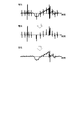
- FIG. 7 is a diagram illustrating an extraction process of a measurement abnormality signal component from an electrocardiogram.
- the upper part of FIG. 7 shows an electrocardiogram without R wave calculated by the R wave removing unit 2131.
- the measurement abnormality signal component extraction unit 2132 performs an extraction method consisting of two steps of extracting the high frequency component after removing the low frequency component.
- Examples of the low-frequency component removal method performed in the first step of the extraction method include a high-pass filter having a fixed cutoff frequency and a variable bandpass filter by removing spectral inclusions by cepstrum analysis.
- FIG. 7 shows the state after the low frequency component is removed from the R waveless electrocardiogram.
- An example of the high frequency component extraction method performed in the second step of the extraction method is the calculation of the peak envelope of the signal.
- the lower part of FIG. 7 shows the calculated envelope with a broken line.
- the high frequency component or envelope is an example of a measurement anomaly signal component.
- the method for extracting the measurement abnormality signal component may be any realization method as long as the envelope as illustrated in FIG. 7 can be calculated.
- the measurement state determination unit 2133 determines the measurement state of the subject's electrocardiogram based on the measurement abnormality signal component extracted by the measurement abnormality signal component extraction unit 2132 (step S5).
- the process of the measurement state determination unit 2133 in step S5 is the process of the third step of the electrocardiogram measurement state evaluation unit 213.
- the measurement state determination unit 2133 can determine the measurement state of the electrocardiogram as a measurement abnormality when the envelope calculated by the measurement abnormality signal component extraction unit 2132 exceeds a certain value.
- the electrocardiogram measurement state evaluation unit 213 may determine the measurement state of the electrocardiogram as a measurement abnormality when the slope of the tangent line of the envelope calculated by the measurement abnormality signal component extraction unit 2132 exceeds a certain value.
- the electrocardiogram measurement state evaluation unit 213 generates measurement state determination information based on the determination of the measurement state of the electrocardiogram. For example, the electrocardiogram measurement state evaluation unit 213 identifies a measurement abnormality section determined to be a measurement abnormality based on the determination of the measurement state of the electrocardiogram.
- the measurement state determination information includes information indicating a measurement abnormality section as a determination result of the measurement state.
- the information indicating the measurement abnormality section may include information indicating the start time of the measurement abnormality and the end time of the measurement abnormality.
- the electrocardiogram measurement state evaluation unit 213 may specify the normal measurement state section determined to be the normal measurement state based on the determination of the measurement state of the electrocardiogram.
- the normal measurement state section is a section other than the measurement abnormality section among the sections measured by the electrocardiogram.
- the measurement state determination information may include information indicating a normal measurement state section as a determination result of the measurement state.
- the information indicating the measurement abnormality section may include information indicating the start time of the normal measurement state and the end time of the normal measurement state.
- the instantaneous heart rate calculation unit 214 calculates the instantaneous heart rate using the R wave extracted by the R wave extraction unit 212 (step S6).
- step S6 for example, the instantaneous heart rate calculation unit 214 calculates the instantaneous heart rate, which is the interval between the two R waves, using two adjacent R waves.
- the instantaneous heartbeat evaluation unit 215 additionally uses the time information of the instantaneous heartbeat
- the instantaneous heartbeat calculation unit 214 stores the time information R wave related information of the instantaneous heartbeat for each instantaneous heartbeat in the instantaneous heartbeat recording unit 232.
- the instantaneous heart rate evaluation unit 215 evaluates the measurement state of the instantaneous heart rate calculated by the instantaneous heart rate calculation unit 214 based on the measurement state determination information generated by the measurement state determination unit 2133 (step S7).
- step S7 in addition to the evaluation of the measured state of the instantaneous heartbeat based on the measurement state determination information, the evaluation of the measured state of the instantaneous heartbeat based on the R wave potential amplitude information and the evaluation of the measured state of the instantaneous heartbeat based on the time information of the instantaneous heartbeat. At least one of the above may be combined.
- the instantaneous heartbeat evaluation unit 215 evaluates the measurement state of the instantaneous heartbeat based on the R wave potential amplitude information and the measurement state of the instantaneous heartbeat based on the time information of the instantaneous heartbeat, and the instantaneous heartbeat based on the measurement state determination information. It is carried out prior to the evaluation of the measurement state of.
- the measurement state of the instantaneous heartbeat is evaluated based only on the measurement state determination information will be described.
- the instantaneous heart rate evaluation unit 215 refers to the information indicating the measurement abnormality section included in the measurement state determination information, considers all R waves detected in the measurement abnormality section as measurement abnormality, and regards the measurement state of the R wave as an artifact. Determine.
- the instantaneous heart rate evaluation unit 215 refers to the information indicating the normal measurement state section included in the measurement state determination information, and determines that the measurement state of all R waves detected in the normal measurement state section is the normal measurement state.
- the instantaneous heart rate evaluation unit 215 refers to the information indicating the measurement abnormality section included in the measurement state determination information, and determines that the measurement state of all R waves detected in the section other than the measurement abnormality section is the normal measurement state. You may.
- the instantaneous heartbeat evaluation unit 215 evaluates an instantaneous heartbeat composed of two adjacent R waves based on the measurement state determined for each R wave. For example, the instantaneous heartbeat evaluation unit 215 assigns evaluation values according to the combination of measurement states of the R waves constituting the instantaneous heartbeat as shown in Table 1 below.
- the instantaneous heart rate evaluation unit 215 shows the combination of the discrimination results of the R wave measurement states constituting the instantaneous heart rate in Table 1. It is one of the patterns indicated by the serial numbers # 1 to # 4 shown in.
- the format of the serial number is not limited to the above.
- the discrimination result "A, R" corresponding to the serial number # 3 in Table 1 is an artifact of the discrimination result of the measurement state of the adjacent first R wave, and the discrimination result of the measurement state of the second R wave. Indicates that the measurement is normal. "A, A” of the discrimination result corresponding to the serial number # 4 in Table 1 indicates that the discrimination results of the measurement states of the adjacent first and second R waves are both artifacts.
- the instantaneous heart rate evaluation unit 215 assigns a separate evaluation value to each state so that the details of the states can be easily distinguished.
- An example of the evaluation value is shown as the "evaluation value” in Table 1. It should be noted that this evaluation value is only an example, and the method of determining the evaluation value is not particularly limited in this embodiment.
- the “evaluation value” in Table 1 will be described. This "evaluation value” determines the reliability of the measurement state of each of the two R waves constituting the instantaneous heartbeat, which is the state shown by the "state details" in the same row in Table 1, between 0 and 1. It is expressed numerically and an arbitrary evaluation value is assigned to each state shown in "Details of state".
- the range of evaluation values and the method of incrementing the evaluation values for each state are not particularly limited. For example, different evaluation values may be assigned to each state in increments of 1 between 1 and 10, and between each state.
- the step size of the evaluation value may be different.
- the length of the horizontal bar graph for example, the longer the length of the horizontal bar graph, the higher the reliability
- the expression of “evaluation value” distinguishes only the combination of the discrimination results of the measurement states of the two R waves constituting the instantaneous heartbeat, and does not distinguish before and after the time series. That is, the "state details" in the serial numbers # 2 and # 3 are the common "normal measurement state in one, and the other is an artifact", and the “evaluation value” in these serial numbers # 2 and # 3 is the “evaluation value” in # 1. It is a common “0.4”, which is 0.6 less than the "evaluation value”.
- serial number # 4 The "state details" in serial number # 4 are "both artifacts", and the "evaluation value” in this serial number # 4 is 0.4 less than the "evaluation value” in # 2 and # 3. The lowest value is "0".
- the instantaneous heart rate evaluation unit 215 generates instantaneous heart rate evaluation information based on the evaluation of the instantaneous heart rate.
- the instantaneous heartbeat evaluation information is information indicating an evaluation value assigned to each instantaneous heartbeat.
- the instantaneous heart rate evaluation unit 215 can generate the instantaneous heart rate evaluation information by using the instantaneous heart rate and the measurement state determination information.
- the instantaneous heart rate abnormal value processing unit 216 processes the abnormal value of the instantaneous heart rate calculated by the instantaneous heart rate calculation unit 214 using the instantaneous heart rate evaluation information generated by the instantaneous heart rate evaluation unit 215 (step S8).
- step S8 for example, the instantaneous heartbeat abnormal value processing unit 216 considers an instantaneous heartbeat having a value lower than the evaluation value set for the abnormal value determination as an abnormal value based on the instantaneous heartbeat evaluation information.
- the instantaneous heartbeat abnormal value processing unit 216 excludes the instantaneous heartbeat deemed to be an abnormal value from the time series data of the instantaneous heartbeat to be handed over to the subsequent processing.
- the specific exclusion method is not particularly limited.
- the evaluation value "1" is required.
- Instantaneous heartbeats having an evaluation value of "0.4" or less are regarded as abnormal values and are excluded from the time series data of the instantaneous heartbeats to be passed to the subsequent processing.
- the specific signal processing method of the measurement abnormality signal component extraction process in step S4 and the determination process of the measurement state of the electrocardiogram in step S5 is not limited to the above example.
- the measurement abnormality signal component extraction unit 2132 can separately process the positive signal component and the negative signal component.
- the measurement state determination unit 2133 may separately determine the measurement state of the electrocardiogram for the positive signal component and the negative signal component.
- the measurement state determination unit 2133 may consider a section determined to be measurement abnormality in any one of the positive signal component and the negative signal component as a measurement abnormality section. Instead of this, the measurement state determination unit 2133 may consider only the section determined to be measurement abnormality in both the positive signal component and the negative signal component as the measurement abnormality section.
- step S4 there is a means for evaluating the positive signal component and the negative signal component together.
- the measurement abnormality signal component extraction unit 2132 can calculate the envelope after folding the negative electrode component toward the positive electrode side by taking the absolute value of the signal or the like.
- the measurement abnormality signal component extraction unit 2132 can calculate the RMS (Root Mean Square) envelope instead of the peak envelope.
- the measurement abnormality signal component extraction unit 2132 can calculate the envelope by combining the positive signal component and the negative signal component by these means, and in step S5, the measurement state determination unit 2133 determines the envelope.
- the measurement state of the electrocardiogram of the subject may be determined based on the envelope.
- step S7 an example in which the instantaneous heart rate evaluation unit 215 generates the instantaneous heart rate evaluation information based only on the measurement state determination information has been described, but the present invention is not limited to this.
- the instantaneous heart rate evaluation unit 215 may generate the instantaneous heart rate evaluation information by further using the R wave potential amplitude information as the evaluation reference of the instantaneous heart rate in addition to the measurement state determination information.
- the instantaneous heart rate evaluation unit 215 adds the evaluation of the instantaneous heart rate measurement state based on the R wave potential amplitude information by a known method or the like to the evaluation of the instantaneous heart rate measurement state based on the above-mentioned measurement state determination information.
- the instantaneous heartbeat evaluation unit 215 can generate instantaneous heartbeat evaluation information based on the evaluation of the measurement state of the instantaneous heartbeat.
- the instantaneous heartbeat evaluation unit 215 may generate the instantaneous heartbeat evaluation information by further using the time information of the instantaneous heartbeat as the evaluation standard of the instantaneous heartbeat in addition to the measurement state determination information.
- the instantaneous heartbeat evaluation unit 215 adds the evaluation of the instantaneous heartbeat measurement state based on the time information of the instantaneous heartbeat by a known method or the like to the evaluation of the instantaneous heartbeat measurement state based on the above-mentioned measurement state determination information. , It is possible to evaluate the measurement state of the instantaneous heartbeat.
- the instantaneous heartbeat evaluation unit 215 can generate instantaneous heartbeat evaluation information based on the evaluation of the measurement state of the instantaneous heartbeat.
- the instantaneous heartbeat evaluation unit 215 may generate the instantaneous heartbeat evaluation information by further using both the R wave potential amplitude information and the time information of the instantaneous heartbeat as the evaluation reference of the instantaneous heartbeat in addition to the measurement state determination information.
- the processing related to measurement abnormality discrimination exemplified in steps S1 to S6 is applied as a method of measurement abnormality discrimination to circulatory system signals having periodic characteristics similar to the electrocardiogram, such as pulse waves and respiratory curves. You may.
- the biometric information processing apparatus 2 determines the measurement state of the electrocardiogram based on the measurement abnormality signal component extracted from the electrocardiogram without R wave. As a result, the biometric information processing apparatus 2 appropriately starts and ends the measurement abnormality having a relatively high frequency signal component by performing signal processing on the R waveless electrocardiogram in which the R wave corresponding to the heartbeat is removed. We will realize an electrocardiogram measurement status evaluation that can be discriminated and only the part where the measurement abnormality has occurred can be judged as an abnormality. The biometric information processing apparatus 2 can evaluate the measurement state of the electrocardiogram, which can accurately determine the abnormality of the instantaneous heartbeat.
- the biometric information processing apparatus 2 accurately captures the start and end of the measurement abnormality in the evaluation of the measurement state of the electrocardiogram, thereby suppressing the erroneous recognition of the R wave that can be normally measured as the measurement abnormality, and the accuracy. It is possible to realize the abnormality discrimination of the instantaneous heartbeat with enhanced.
- the biological information processing apparatus 2 generates the instantaneous heartbeat evaluation information using the instantaneous heartbeat and the measurement state determination information, and performs the abnormal value processing of the instantaneous heartbeat using the instantaneous heartbeat evaluation information.
- the biometric information processing apparatus 2 excludes the abnormal value of the instantaneous heartbeat by using the measurement state determination information, thereby suppressing the erroneous recognition of the R wave that can be normally measured as a measurement abnormality, and the signal. It is possible to discriminate an artifact that is difficult to discriminate only by the frequency characteristic and the potential amplitude characteristic of the above, and it is possible to reduce the influence on the heart rate variability analysis.
- the biometric information processing apparatus 2 further uses the R wave potential amplitude information to generate instantaneous heartbeat evaluation information.
- the biometric information processing apparatus 2 can generate more accurate instantaneous heartbeat evaluation information by additionally considering the R wave potential amplitude information.
- the biometric information processing apparatus 2 further uses the time information of the instantaneous heartbeat to generate the instantaneous heartbeat evaluation information.
- the biometric information processing apparatus 2 can generate more accurate instantaneous heartbeat evaluation information by additionally considering the time information of the instantaneous heartbeat.
- the biometric information processing apparatus 2 identifies a measurement abnormality section based on the determination of the measurement state of the electrocardiogram. As a result, the biometric information processing apparatus 2 accurately captures the measurement abnormality section, thereby suppressing the erroneous recognition of the normally measured R wave as a measurement abnormality, and at the same time, improving the accuracy of the instantaneous heartbeat abnormality determination. Is feasible.
- the present invention is not limited to the above embodiment, and can be variously modified at the implementation stage without departing from the gist thereof.
- each embodiment may be carried out in combination as appropriate as possible, in which case the combined effect can be obtained.
- the above-described embodiment includes inventions at various stages, and various inventions can be extracted by an appropriate combination in a plurality of disclosed constituent requirements.
- the method described in the embodiment is, as a program (software) that can be executed by a computer (computer), for example, a magnetic disk (hard disk, etc.), an optical disk (CD-ROM, DVD, etc.), a semiconductor memory (ROM, RAM). , Flash memory, etc.), and can also be transmitted and distributed via a communication medium.
- the program stored on the medium side also includes a setting program for configuring the software (including not only the execution program but also the table and the data structure) to be executed by the computer in the computer.
- the computer that realizes this device reads the program recorded on the recording medium, builds software by the setting program in some cases, and executes the above-mentioned processing by controlling the operation by this software.
- the recording medium referred to in the present specification is not limited to distribution, and includes a storage medium such as a magnetic disk or a semiconductor memory provided in a device connected inside a computer or via a network.
- ECG measuring device 2 Biometric information processing device 21
- Control unit 22 Communication I / F 23 Storage unit 211
- ECG acquisition unit 212 R wave extraction unit 213
- ECG measurement status evaluation unit 214 Instantaneous heart rate calculation unit 215
- Instantaneous heart rate evaluation unit 216 Instantaneous heart rate abnormal value processing unit 2131
- R wave removal unit 2132 Measurement abnormality signal component extraction unit 2133 Measurement status Judgment unit 231
- R wave related information recording unit 232 Instantaneous heart rate recording unit ART1 artifact ART2 artifact NOI noise RW R wave RRI instantaneous heart rate S biometric information processing system
Landscapes
- Health & Medical Sciences (AREA)
- Life Sciences & Earth Sciences (AREA)
- Cardiology (AREA)
- Heart & Thoracic Surgery (AREA)
- Molecular Biology (AREA)
- Pathology (AREA)
- Engineering & Computer Science (AREA)
- Biomedical Technology (AREA)
- Physics & Mathematics (AREA)
- Medical Informatics (AREA)
- Biophysics (AREA)
- Surgery (AREA)
- Animal Behavior & Ethology (AREA)
- General Health & Medical Sciences (AREA)
- Public Health (AREA)
- Veterinary Medicine (AREA)
- Measurement And Recording Of Electrical Phenomena And Electrical Characteristics Of The Living Body (AREA)
Abstract
Dans un mode de réalisation de la présente, un dispositif de traitement d'informations biologiques comprend : une unité d'acquisition d'électrocardiogramme qui acquiert un électrocardiogramme d'un sujet; une unité d'extraction d'onde R qui extrait une onde R de l'électrocardiogramme; une unité d'élimination d'onde R qui élimine l'onde R de l'électrocardiogramme et calcule un électrocardiogramme sans onde R dans lequel l'onde R n'est pas comprise; une unité d'extraction de composante de signal d'anomalie de mesure qui extrait une composante de signal d'anomalie de mesure à partir de l'électrocardiogramme sans onde R; et une unité de détermination d'état de mesure qui détermine, sur la base de la composante de signal d'anomalie de mesure, un état de mesure de l'électrocardiogramme du sujet, et génère des informations de détermination d'état de mesure comprenant le résultat de détermination de l'état de mesure de l'électrocardiogramme.
Priority Applications (1)
| Application Number | Priority Date | Filing Date | Title |
|---|---|---|---|
| PCT/JP2020/022760 WO2021250794A1 (fr) | 2020-06-10 | 2020-06-10 | Dispositif de traitement d'informations biologiques, procédé de traitement d'informations biologiques et programme de traitement d'informations biologiques |
Applications Claiming Priority (1)
| Application Number | Priority Date | Filing Date | Title |
|---|---|---|---|
| PCT/JP2020/022760 WO2021250794A1 (fr) | 2020-06-10 | 2020-06-10 | Dispositif de traitement d'informations biologiques, procédé de traitement d'informations biologiques et programme de traitement d'informations biologiques |
Publications (1)
| Publication Number | Publication Date |
|---|---|
| WO2021250794A1 true WO2021250794A1 (fr) | 2021-12-16 |
Family
ID=78845505
Family Applications (1)
| Application Number | Title | Priority Date | Filing Date |
|---|---|---|---|
| PCT/JP2020/022760 WO2021250794A1 (fr) | 2020-06-10 | 2020-06-10 | Dispositif de traitement d'informations biologiques, procédé de traitement d'informations biologiques et programme de traitement d'informations biologiques |
Country Status (1)
| Country | Link |
|---|---|
| WO (1) | WO2021250794A1 (fr) |
Citations (7)
| Publication number | Priority date | Publication date | Assignee | Title |
|---|---|---|---|---|
| JPH0630908A (ja) * | 1992-03-27 | 1994-02-08 | Nippon Koden Corp | 微小心電図計測装置 |
| JPH1057330A (ja) * | 1996-08-20 | 1998-03-03 | Chiyuunichi Denshi:Kk | 心電図波形のドリフト除去装置 |
| JP2009261723A (ja) * | 2008-04-25 | 2009-11-12 | Fukuda Denshi Co Ltd | 心電計及びその制御方法 |
| WO2017090732A1 (fr) * | 2015-11-25 | 2017-06-01 | 日本電信電話株式会社 | Procédé et dispositif d'évaluation respiratoire |
| JP2017192607A (ja) * | 2016-04-22 | 2017-10-26 | ユニオンツール株式会社 | 心電図自動解析装置 |
| JP2018094156A (ja) * | 2016-12-14 | 2018-06-21 | 日本電信電話株式会社 | 瞬時心拍信頼性評価装置、方法およびプログラム |
| JP2018201800A (ja) * | 2017-06-02 | 2018-12-27 | 日本電信電話株式会社 | 期外収縮判別装置、期外収縮判別方法及びプログラム |
-
2020
- 2020-06-10 WO PCT/JP2020/022760 patent/WO2021250794A1/fr active Application Filing
Patent Citations (7)
| Publication number | Priority date | Publication date | Assignee | Title |
|---|---|---|---|---|
| JPH0630908A (ja) * | 1992-03-27 | 1994-02-08 | Nippon Koden Corp | 微小心電図計測装置 |
| JPH1057330A (ja) * | 1996-08-20 | 1998-03-03 | Chiyuunichi Denshi:Kk | 心電図波形のドリフト除去装置 |
| JP2009261723A (ja) * | 2008-04-25 | 2009-11-12 | Fukuda Denshi Co Ltd | 心電計及びその制御方法 |
| WO2017090732A1 (fr) * | 2015-11-25 | 2017-06-01 | 日本電信電話株式会社 | Procédé et dispositif d'évaluation respiratoire |
| JP2017192607A (ja) * | 2016-04-22 | 2017-10-26 | ユニオンツール株式会社 | 心電図自動解析装置 |
| JP2018094156A (ja) * | 2016-12-14 | 2018-06-21 | 日本電信電話株式会社 | 瞬時心拍信頼性評価装置、方法およびプログラム |
| JP2018201800A (ja) * | 2017-06-02 | 2018-12-27 | 日本電信電話株式会社 | 期外収縮判別装置、期外収縮判別方法及びプログラム |
Non-Patent Citations (1)
| Title |
|---|
| SUN, P. ET AL.: "An Improved Morphological Approach to Background Normalization of ECG Signals", IEEE TRANSACTIONS ON BIOMEDICAL ENGINEERING, vol. 50, no. 1, 2003, pages 117 - 121, XP011070477 * |
Similar Documents
| Publication | Publication Date | Title |
|---|---|---|
| US20200187806A1 (en) | Methods And Systems For Predicting Hypovolemic Hypotensive Conditions Resulting From Bradycardia Behavior Using A Pulse Volume Waveform | |
| US20090112110A1 (en) | System for Cardiac Medical Condition Detection and Characterization | |
| US20170273586A1 (en) | Patient Signal Analysis Based on Vector Analysis | |
| JP6133708B2 (ja) | 生体情報表示装置および生体情報表示装置の作動方法 | |
| Dos Santos et al. | Application of an automatic adaptive filter for heart rate variability analysis | |
| KR102482796B1 (ko) | 원격 광용적맥파 측정을 이용한 비접촉 심박 변이도 분석 장치 및 방법 | |
| Mazidi et al. | Detection of premature ventricular contraction (PVC) using linear and nonlinear techniques: an experimental study | |
| US20200305734A1 (en) | Non-invasive analysis of sinoatrial node and autonomic nervous input to heart function | |
| WO2020166366A1 (fr) | Dispositif de calcul de quantité de caractéristiques temporelles, procédé de calcul et programme associé | |
| WO2019225662A1 (fr) | Dispositif, procédé et programme d'évaluation de fiabilité de battement de cœur instantané | |
| US20210007621A1 (en) | Method to analyze cardiac rhythms using beat-to-beat display plots | |
| JP6692283B2 (ja) | 瞬時心拍信頼性評価装置、方法およびプログラム | |
| Pereira et al. | Robust assessment of photoplethysmogram signal quality in the presence of atrial fibrillation | |
| WO2021250794A1 (fr) | Dispositif de traitement d'informations biologiques, procédé de traitement d'informations biologiques et programme de traitement d'informations biologiques | |
| Akhter et al. | Computer based RR-interval detection system with ectopy correction in HRV data | |
| Magrupov et al. | ECG signal processing algorithms to determine heart rate | |
| US8301230B2 (en) | Method for reducing baseline drift in a biological signal | |
| JP6857582B2 (ja) | 瞬時心拍の時系列データの補完装置、補完方法及びそのプログラム | |
| Jain et al. | LABVIEW based expert system for detection of heart abnormalities | |
| Hegde et al. | A review on ECG signal processing and HRV analysis | |
| Gibbs et al. | A universal, high‐performance ECG signal processing engine to reduce clinical burden | |
| Acharya et al. | Integrated index for cardiac arrythmias diagnosis using entropies as features of heart rate variability signal | |
| Jelinek et al. | Multiscale renyi entropy and cardiac autonomic neuropathy | |
| US9538930B2 (en) | Linear multi-domain electrocardiogram | |
| JP6807279B2 (ja) | 期外収縮判別装置、期外収縮判別方法及びプログラム |
Legal Events
| Date | Code | Title | Description |
|---|---|---|---|
| 121 | Ep: the epo has been informed by wipo that ep was designated in this application |
Ref document number: 20940296 Country of ref document: EP Kind code of ref document: A1 |
|
| NENP | Non-entry into the national phase |
Ref country code: DE |
|
| 122 | Ep: pct application non-entry in european phase |
Ref document number: 20940296 Country of ref document: EP Kind code of ref document: A1 |
|
| NENP | Non-entry into the national phase |
Ref country code: JP |