WO2021250794A1 - Biological information processing device, biological information processing method, and biological information processing program - Google Patents
Biological information processing device, biological information processing method, and biological information processing program Download PDFInfo
- Publication number
- WO2021250794A1 WO2021250794A1 PCT/JP2020/022760 JP2020022760W WO2021250794A1 WO 2021250794 A1 WO2021250794 A1 WO 2021250794A1 JP 2020022760 W JP2020022760 W JP 2020022760W WO 2021250794 A1 WO2021250794 A1 WO 2021250794A1
- Authority
- WO
- WIPO (PCT)
- Prior art keywords
- electrocardiogram
- wave
- measurement
- unit
- instantaneous
- Prior art date
Links
Images


Classifications
-
- A—HUMAN NECESSITIES
- A61—MEDICAL OR VETERINARY SCIENCE; HYGIENE
- A61B—DIAGNOSIS; SURGERY; IDENTIFICATION
- A61B5/00—Measuring for diagnostic purposes; Identification of persons
- A61B5/24—Detecting, measuring or recording bioelectric or biomagnetic signals of the body or parts thereof
- A61B5/316—Modalities, i.e. specific diagnostic methods
- A61B5/318—Heart-related electrical modalities, e.g. electrocardiography [ECG]
- A61B5/346—Analysis of electrocardiograms
Definitions
- One aspect of the present invention relates to a biometric information processing apparatus, a biometric information processing method, and a biometric information processing program.
- both autonomic nerves There are two autonomic nerves, the sympathetic nerve and the vagus nerve. Both autonomic nerves are widely distributed in each organ and control involuntary physical functions such as circulation and metabolism. In many cases, it is said that both autonomic nerves dominate one organ antagonistically.
- sympathetic nerve activity which is one of the autonomic nerve activities, is enhanced by stress stimuli such as mental arithmetic load.
- vagus nerve which is another autonomic nerve, is often understood in the same way as parasympathetic nerve activity because it is mainly responsible for parasympathetic nerve activity in each organ controlled by the nerve.
- the "vagus nerve” is the name of the Xth nerve, which is one of the cranial nerves, and refers to all the nerves from the brain to each organ. Therefore, the parasympathetic nerve activity in the target organ may be indicated by adding the name of the organ to be controlled (eg, cardiac vagus nerve).
- the heart is one of the organs controlled by the autonomic nerves.
- the heart is antagonized by the sympathetic and vagus nerves and is said to reflect the static balance of both autonomic nerve activities.
- RRI instantaneous heartbeat
- the R wave is one of the electrocardiographic waveforms obtained by the electrocardiogram measurement, and reflects the depolarizing activity of the heart.
- the low frequency component (hereinafter, also referred to as HRV LF ) when the instantaneous heartbeats at unequal intervals are analyzed by the frequency spectrum is interpreted as an index reflecting the sympathetic nerve activity and the cardiac vagus nerve activity. ..
- the high frequency component (hereinafter, also referred to as HRV HF ) is interpreted as an index reflecting the cardiac vagus nerve activity.
- a wearable device such as a Holter electrocardiograph.
- measurement abnormalities occur due to electrode abnormalities such as electrode deformation and displacement, or various factors such as body movement, sweating, and static electricity.
- This measurement abnormality can be confirmed on the electrocardiogram in the form of artifacts and noise.
- the duration of both noise and artifact changes depending on the duration of the measurement abnormality.
- the waveform observed as an artifact has a frequency characteristic very similar to that of the R wave, so it is very difficult to completely remove it by general filtering. Therefore, the algorithm that analyzes the electrocardiogram and extracts the R wave may mistakenly determine the artifact as the R wave and extract it.
- HRV LF and HRV HF reflect autonomic nervous activity only if all the data to be analyzed are normal instantaneous heartbeats.
- the normal state here means a state in which there is no abnormality in both the measurement target and the measuring instrument.
- the abnormality to be measured refers to the arrhythmia of the subject.
- the abnormality of the measuring instrument refers to the state in which the measurement abnormality has occurred on the electrocardiogram.
- An artifact that is one of the measurement abnormalities is misjudged as an R wave, and does not reflect the depolarizing activity of the heart at all due to its generation mechanism. Therefore, if at least one of the R waves constituting the instantaneous heartbeat to be analyzed is erroneously determined that the artifact is an R wave, neither HRV LF nor HRV HF can be said to reflect the autonomic nervous activity. ..
- Method 1 The measurement state of the instantaneous heartbeat is discriminated based on the potential amplitude information of each of the two R waves constituting the instantaneous heartbeat, and the instantaneous heartbeat that seems to be a measurement abnormality is excluded (see, for example, Non-Patent Document 1).
- Method 2 In order to detect measurement abnormalities (eg, myoelectric artifacts, etc.) that have potential amplitude characteristics equivalent to R waves, which is difficult to deal with by Method 1, the measurement state of the target ECG is evaluated in advance using statistical features. Then, the information is given to the R wave constituting the instantaneous heartbeat. Then, the reliability of the instantaneous heartbeat is evaluated based on the potential information of the two R waves constituting the instantaneous heartbeat, and the instantaneous heartbeat that seems to be a measurement abnormality is excluded (see, for example, Non-Patent Document 2).
- measurement abnormalities eg, myoelectric artifacts, etc.
- Kana Eguchi, et al. “RRI measurement reliability evaluation for wearable electrocardiographs using QRS complex potential characteristics”, Shingaku Giho Vol.116, No.412, pp.171-176, 2017 K.
- Eguchi, et.al “RR Interval Outlier Exclusion Method Based on Statistical ECG Values Targeting HRV Analysis Using Wearable ECG Devices”, Proceedings of the 40th Annual International Conference of the IEEE Engineering in pp. 5689-5692, 2018.
- the above method 1 overcomes the problem of general filtering by using the potential amplitude information of the R wave constituting the instantaneous heartbeat.
- the measurement abnormality that occurs in the electrocardiogram does not always have the potential amplitude characteristic different from that of the R wave.
- an R wave such as a myoelectric artifact in which the potential amplitude characteristic equivalent to that of the R wave is erroneously determined cannot be detected as an abnormality.
- the above method 2 uses statistical features for each arbitrary time length in order to detect measurement abnormalities (eg, myoelectric artifacts, etc.) having potential amplitude characteristics equivalent to R waves, which are difficult to deal with by method 1.
- measurement abnormalities eg, myoelectric artifacts, etc.
- the problem of the method 1 is overcome.
- the measurement state evaluation result based on the statistical feature amount to the entire electrocardiogram used for calculating the feature amount the R wave that can be measured normally may be mistakenly regarded as a measurement abnormality.
- the present invention has been made by paying attention to the above circumstances, and is intended to provide a technique for improving the accuracy of determining an abnormality in an instantaneous heartbeat.
- the biometric information device has an electrocardiogram acquisition unit that acquires an electrocardiogram of a subject, an R wave extraction unit that extracts an R wave from the electrocardiogram, and an R wave extraction unit that removes the R wave from the electrocardiogram.
- An R wave removing unit that calculates an R waveless ECG that does not include waves, a measurement abnormality signal component extraction unit that extracts measurement abnormality signal components from the R waveless ECG, and the subject's measurement abnormality signal component based on the measurement abnormality signal component. It is provided with a measurement state determination unit that determines the measurement state of the electrocardiogram and generates measurement state determination information including the determination result of the measurement state of the electrocardiogram.
- the accuracy of determining abnormalities in instantaneous heartbeat can be improved.
- FIG. 1 is a schematic diagram of a biometric information processing system according to an embodiment of the present invention.
- FIG. 2 is a diagram showing the relationship between the R wave and the instantaneous heartbeat (RRI) in the electrocardiogram according to the embodiment of the present invention.
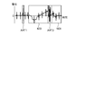
- FIG. 3 is a diagram showing an example of measurement abnormality in the electrocardiogram according to the embodiment of the present invention.
- FIG. 4 is a block diagram showing a software configuration of the biometric information processing apparatus according to the embodiment of the present invention.
- FIG. 5 is a flowchart showing a processing procedure and processing contents of the biometric information processing apparatus according to the embodiment of the present invention.
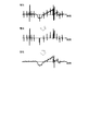
- FIG. 6 is a diagram illustrating an R wave removal process from the electrocardiogram according to the embodiment of the present invention.
- FIG. 7 is a diagram illustrating an extraction process of a measurement abnormality signal component according to the embodiment of the present invention.
- FIG. 1 is a schematic diagram of a biometric information processing system S.
- the biometric information processing system S includes an electrocardiogram measuring device 1 and a biometric information processing device 2.
- the electrocardiogram measuring device 1 measures the electrocardiogram of the subject and sends the measured electrocardiogram to the biometric information processing device 2.
- the electrocardiogram measuring device 1 measures an electrocardiogram with at least two electrodes.
- the electrocardiogram represents the circulatory system biological signals, eg, periodic signals synchronized with the contraction of the ventricles, over time.
- the electrocardiogram is sometimes called an electrocardiographic waveform. That is, the electrocardiogram contains time-series data capable of extracting an electrocardiogram corresponding to an R wave that reflects the depolarizing activity of the heart.
- the electrocardiogram measuring device 1 only needs to be able to measure the electrocardiogram equivalent to the R wave, and the realized form including the recording method of the measured electrocardiogram does not matter.
- the electrocardiogram measuring device 1 can be formed as a wearable device that can be attached to a subject such as a halter electrocardiograph and can record the measured electrocardiogram in the electrocardiogram measuring device 1.
- the electrocardiogram measuring device 1 records the electrocardiogram measured in its own device when the electrocardiogram measuring device 1 and the biometric information processing device 2 are configured separately, and the electrocardiogram measuring device 1 and the biometric information processing device 2 are separate from each other. Because it works.
- the biometric information processing apparatus 2 may acquire the electrocardiogram recorded in the electrocardiogram measuring device 1 in batch after the electrocardiogram measuring device 1 completes the measurement of the electrocardiogram, and may process the electrocardiogram in batch processing. .. Further, the electrocardiogram measuring device 1 may be integrally formed with the biometric information processing device 2, that is, the biometric information processing system S may be realized as one wearable device. When integrally formed in this way, the information processing apparatus 2 may process each process related to the electrocardiogram, which will be described later, in real time at the same time as the measurement of the electrocardiogram by the electrocardiogram measuring device 1. In this example, the electrocardiogram measuring device 1 does not have to record the electrocardiogram measured in its own device.
- the electrocardiogram measuring device 1 may be provided outside the biometric information processing system S.
- the heart rate variability analysis system S may capture the result of measuring the electrocardiogram of the subject from an external device corresponding to the electrocardiogram measuring device 1 into the biometric information processing device 2 via a network such as the Internet.
- the biometric information processing device 2 takes in the electrocardiogram measured by the electrocardiogram measuring device 1 and processes the electrocardiogram.
- the biometric information processing apparatus 2 can be realized by, for example, a dedicated hardware equipped with a microcomputer, a smartphone, a tablet terminal, a computer device such as a personal computer (PC).
- the biometric information processing device 2 includes a control unit 21, a communication I / F (interface) 22, and a storage unit 23.
- the control unit 21, the communication I / F 22, and the storage unit 23 are communicably connected to each other via a bus.
- the control unit 21 controls the biometric information processing device 2.
- the control unit 21 includes a hardware processor such as a central processing unit (CPU).
- the communication I / F 22 is an interface that enables communication with the electrocardiogram measuring device 1.
- the communication I / F 22 enables wired communication or wireless communication with the electrocardiogram measuring device 1 according to a predetermined standard.
- the storage unit 23 is a storage medium.
- the storage unit 23 includes a non-volatile memory such as an HDD (Hard Disk Drive) or SSD (Solid State Drive) that can be written and read at any time, and a non-volatile memory such as a ROM (Read Only Memory). It is configured in combination with a volatile memory such as RAM (Random Access Memory).
- the storage unit 23 includes a program storage area and a data storage area in the storage area.
- the program storage area stores application programs necessary for executing various processes, in addition to middleware such as an OS (Operating System).
- FIG. 2 is a diagram showing the relationship between the R wave and the instantaneous heartbeat in the electrocardiogram.
- the electrocardiogram is represented as a change in potential measured by the electrodes of at least two poles with time, and includes an R wave RW that reflects the depolarizing activity of the heart.
- the interval between two adjacent R-wave RWs is the instantaneous heart rate RRI.
- FIG. 3 is a diagram showing an example of measurement abnormality in an electrocardiogram. That is, the measurement abnormality can be confirmed on the electrocardiogram in the form of artifact ART1 and artifact ART2 or noise NOI as shown in FIG.
- the duration of the artifact ART1, the artifact ART2, and the noise NOI varies depending on the duration of the measurement abnormality.
- FIG. 4 is a block diagram showing a software configuration of the biometric information processing apparatus 2.
- the control unit 21 activates the electrocardiogram acquisition unit 211, the R wave extraction unit 212, the electrocardiogram measurement state evaluation unit 213, the instantaneous heart rate calculation unit 214, and the instantaneous heart rate evaluation unit. 215 and the instantaneous heartbeat abnormal value processing unit 216 are executed.
- the electrocardiogram acquisition unit 211 acquires the electrocardiogram of the subject. Specifically, the control unit 21 takes in the electrocardiogram from the electrocardiogram measuring device 1 via the communication I / F 22 and stores it in the storage unit 23. Further, the control unit 21 receives the electrocardiogram measured by the external device corresponding to the electrocardiogram measuring device 1 from the device or from the server or the like in which the measured electrocardiogram is stored by the communication I / F 22 via the network. It may be stored in the storage unit 23. Further, although not particularly shown, when the communication I / F 22 has a removable media (memory card) read function that can be attached to and detached from the biometric information processing apparatus 2, the control unit 21 measures the electrocardiogram. It is also possible to acquire an electrocardiogram measured by the device 1 or an external device corresponding to the electrocardiogram measuring device 1 via the storage medium thereof.
- the R wave extraction unit 212 extracts the R wave from the electrocardiogram acquired by the electrocardiogram acquisition unit 211.
- the R wave extraction unit 212 analyzes the electrocardiogram acquired by the electrocardiogram acquisition unit 211 stored in the storage unit 23, and extracts the R wave. In the embodiment, a specific method for extracting R waves does not matter.
- the R wave extraction unit 212 stores R wave related information in the R wave related information recording unit 231 for each extracted R wave.
- the R wave-related information is information related to the extracted R wave.
- the R wave related information includes R wave potential amplitude information based on the potential information.
- the potential information is information regarding the potential of the R wave
- the R wave potential amplitude information is information indicating the amplitude of the potential of the R wave.
- the R wave related information recording unit 231 is realized in a part of the data storage area of the storage unit 23.
- the R wave related information recording unit 231 records R wave related information for each R wave extracted by the R wave extraction unit 212.
- the R wave related information recording unit 231 records the R wave potential amplitude information based on the potential information.
- the R wave potential amplitude information is an example of information that can distinguish at least two types of R wave measurement states, a normal measurement state and an artifact.
- the R wave related information recording unit 231 uses information that can distinguish at least two types of normal measurement state and artifact as the R wave measurement state as the R wave related information to be recorded, but particularly specifies other information. do not do.
- the R wave-related information recording unit 231 may use the information regarding the time when the R wave extracted by the R wave extraction unit 212 appears as the R wave-related information to be recorded. Further, the specific recording format of the R wave related information is not specified. Recording of R wave related information by the R wave related information recording unit 231 is not essential, but the instantaneous heart rate evaluation unit 215 additionally uses the R wave potential amplitude information to evaluate the instantaneous heart rate based on the R wave measurement state. It is necessary for the case.
- the electrocardiogram measurement state evaluation unit 213 evaluates the measurement state of the electrocardiogram based on the electrocardiogram measured by the electrocardiogram measuring device 1.
- the electrocardiogram measurement state evaluation unit 213 includes an R wave removing unit 2131, a measurement abnormality signal component extraction unit 2132, and a measurement state determination unit 2133.
- the R wave removing unit 2131 removes the R wave acquired by the R wave extraction unit 212 from the electrocardiogram acquired by the electrocardiogram acquisition unit 211.
- the R wave removing unit 2131 calculates an electrocardiogram without an R wave that does not include the R wave.
- the measurement abnormality signal component extraction unit 2132 extracts the measurement abnormality signal component from the R waveless electrocardiogram calculated by the R wave removal unit 2131.
- the measurement state determination unit 2133 determines the measurement state of the subject's electrocardiogram based on the measurement abnormality signal component extracted by the measurement abnormality signal component extraction unit 2132.
- the measurement state determination unit 2133 generates measurement state determination information based on the determination.
- the measurement state determination information is information including the determination result of the measurement state of the electrocardiogram.
- the instantaneous heart rate calculation unit 214 calculates the instantaneous heart rate of the subject, which is the interval between two adjacent R waves in time series, using the R wave extracted by the R wave extraction unit 212. When necessary for subsequent processing, the instantaneous heart rate calculation unit 214 stores the calculated instantaneous heart rate information regarding the instantaneous heart rate in the instantaneous heart rate recording unit 232.
- the instantaneous heart rate recording unit 232 is realized in a part of the data storage area of the storage unit 23.
- the instantaneous heartbeat recording unit 232 records instantaneous heartbeat information for each instantaneous heartbeat calculated by the instantaneous heartbeat calculation unit 214.
- the specific recording format of the information in the instantaneous heart rate recording unit 232 is not particularly specified.
- the instantaneous heartbeat information is a matrix of instantaneous heartbeats, a data matrix composed of two elements, the time information of the first R wave (time information of instantaneous heartbeats) and the momentary heartbeats. Is possible.
- the instantaneous heart rate evaluation unit 215 generates instantaneous heart rate evaluation information using the instantaneous heart rate calculated by the instantaneous heart rate calculation unit 214 and the measurement state determination information generated by the measurement state determination unit 2133.
- the instantaneous heartbeat evaluation information is information indicating the evaluation of the instantaneous heartbeat.
- an evaluation standard other than the measurement state determination information may be used.
- the evaluation of the instantaneous heartbeat may take into account the R wave potential amplitude information.
- the instantaneous heart rate evaluation unit 215 generates the instantaneous heart rate evaluation information by further using the R wave potential amplitude information recorded in the R wave related information recording unit 231 in addition to the instantaneous heart rate and the measurement state determination information.
- the evaluation of the instantaneous heartbeat may take into account the time information of the instantaneous heartbeat.
- the instantaneous heart rate evaluation unit 215 generates the instantaneous heart rate evaluation information by further using the instantaneous heart rate time information recorded in the instantaneous heart rate recording unit 232 in addition to the instantaneous heart rate and the measurement state determination information.
- the evaluation of the instantaneous heartbeat may consider the R wave potential amplitude information and the time information of the instantaneous heartbeat.
- the instantaneous heartbeat evaluation unit 215 generates the instantaneous heartbeat evaluation information by further using the R wave potential amplitude information and the time information of the instantaneous heartbeat in addition to the instantaneous heartbeat and the measurement state determination information.
- the instantaneous heart rate abnormal value processing unit 216 processes the abnormal value of the instantaneous heart rate calculated by the instantaneous heart rate calculation unit 214 using the instantaneous heart rate evaluation information generated by the instantaneous heart rate evaluation unit 215.
- FIG. 5 is a flowchart showing a processing procedure and processing contents of the biometric information processing apparatus 2.
- a method will be described in which an artifact that is difficult to discriminate based on the potential amplitude characteristic of the R wave is targeted, and an artifact that is erroneously determined is excluded as an abnormal value.
- the processing procedure described below is only an example, and each processing may be changed as much as possible. Further, with respect to the processing procedure described below, steps can be omitted, replaced, and added as appropriate according to the embodiment.
- the electrocardiogram acquisition unit 211 acquires the electrocardiogram of the subject (step S1). In step S1, the electrocardiogram acquisition unit 211 acquires the electrocardiogram of the subject measured by the electrocardiogram measuring device 1. The electrocardiogram acquisition unit 211 sends the acquired electrocardiogram to the R wave extraction unit 212.
- the R wave extraction unit 212 extracts the R wave from the electrocardiogram acquired by the electrocardiogram acquisition unit 211 (step S2). In step S2, for example, the R wave extraction unit 212 extracts the R wave from the electrocardiogram based on the analysis of the electrocardiogram. When the instantaneous heart rate evaluation unit 215 additionally uses the R wave potential amplitude information, the R wave extraction unit 212 stores the R wave related information for each extracted R wave in the R wave related information recording unit 231.
- the R wave removing unit 2131 removes the R wave from the electrocardiogram and calculates an electrocardiogram without the R wave (step S3).
- the processing of the R wave removing unit 2131 in step S3 is the processing of the first step of the electrocardiogram measurement state evaluation unit 213.
- the R wave removing unit 2131 is a component corresponding to the R wave from the electrocardiogram based on the electrocardiogram information acquired by the electrocardiogram acquisition unit 211 and the R wave information acquired by the R wave extraction unit 212. To remove.
- FIG. 6 is a diagram illustrating the process of removing the R wave from the electrocardiogram.
- the upper part of FIG. 6 shows an electrocardiogram measured by the electrocardiogram measuring device 1.
- the R wave removing unit 2131 cuts out the values measured during an arbitrary time before and after the observation time of each R wave extracted by the R wave extracting unit 212, and creates a new matrix A.
- the middle part of FIG. 6 shows the values measured during an arbitrary time before and after the observation time of each R wave.
- the arbitrary time is 0.10 seconds, which is the normal duration of the QRS complex including the R wave.
- the arbitrary time is not limited to this as long as it is a time width in which a component that seems to be an R wave can be removed.
- the R wave removing unit 2131 realizes the removing process of the R wave from the electrocardiogram by subtracting the matrix A from the electrocardiogram measured by the electrocardiogram measuring device 1.
- the R wave removing unit 2131 calculates an R waveless ECG obtained by subtracting the matrix A from the ECG.
- the lower part of FIG. 6 shows an electrocardiogram without R wave.
- the process of removing the R wave from the electrocardiogram may be any method as long as it is possible to remove the R wave from the electrocardiogram, and is not limited to the method illustrated in FIG.
- the measurement abnormality signal component extraction unit 2132 extracts the measurement abnormality signal component from the R waveless electrocardiogram calculated by the R wave removal unit 2131 (step S4).
- the processing of the measurement abnormality signal component extraction unit 2132 in step S4 is the processing of the second step of the electrocardiogram measurement state evaluation unit 213.
- the measurement abnormality signal component extraction unit 2132 extracts the measurement abnormality signal component to be detected from the R waveless electrocardiogram.
- the measurement abnormality signal component to be detected is "an artifact that is difficult to discriminate based on the potential amplitude characteristic of the R wave".
- the "artifact that is difficult to discriminate based on the potential amplitude characteristic of the R wave” is the artifact ART2 exemplified in FIG.
- FIG. 7 is a diagram illustrating an extraction process of a measurement abnormality signal component from an electrocardiogram.
- the upper part of FIG. 7 shows an electrocardiogram without R wave calculated by the R wave removing unit 2131.
- the measurement abnormality signal component extraction unit 2132 performs an extraction method consisting of two steps of extracting the high frequency component after removing the low frequency component.
- Examples of the low-frequency component removal method performed in the first step of the extraction method include a high-pass filter having a fixed cutoff frequency and a variable bandpass filter by removing spectral inclusions by cepstrum analysis.
- FIG. 7 shows the state after the low frequency component is removed from the R waveless electrocardiogram.
- An example of the high frequency component extraction method performed in the second step of the extraction method is the calculation of the peak envelope of the signal.
- the lower part of FIG. 7 shows the calculated envelope with a broken line.
- the high frequency component or envelope is an example of a measurement anomaly signal component.
- the method for extracting the measurement abnormality signal component may be any realization method as long as the envelope as illustrated in FIG. 7 can be calculated.
- the measurement state determination unit 2133 determines the measurement state of the subject's electrocardiogram based on the measurement abnormality signal component extracted by the measurement abnormality signal component extraction unit 2132 (step S5).
- the process of the measurement state determination unit 2133 in step S5 is the process of the third step of the electrocardiogram measurement state evaluation unit 213.
- the measurement state determination unit 2133 can determine the measurement state of the electrocardiogram as a measurement abnormality when the envelope calculated by the measurement abnormality signal component extraction unit 2132 exceeds a certain value.
- the electrocardiogram measurement state evaluation unit 213 may determine the measurement state of the electrocardiogram as a measurement abnormality when the slope of the tangent line of the envelope calculated by the measurement abnormality signal component extraction unit 2132 exceeds a certain value.
- the electrocardiogram measurement state evaluation unit 213 generates measurement state determination information based on the determination of the measurement state of the electrocardiogram. For example, the electrocardiogram measurement state evaluation unit 213 identifies a measurement abnormality section determined to be a measurement abnormality based on the determination of the measurement state of the electrocardiogram.
- the measurement state determination information includes information indicating a measurement abnormality section as a determination result of the measurement state.
- the information indicating the measurement abnormality section may include information indicating the start time of the measurement abnormality and the end time of the measurement abnormality.
- the electrocardiogram measurement state evaluation unit 213 may specify the normal measurement state section determined to be the normal measurement state based on the determination of the measurement state of the electrocardiogram.
- the normal measurement state section is a section other than the measurement abnormality section among the sections measured by the electrocardiogram.
- the measurement state determination information may include information indicating a normal measurement state section as a determination result of the measurement state.
- the information indicating the measurement abnormality section may include information indicating the start time of the normal measurement state and the end time of the normal measurement state.
- the instantaneous heart rate calculation unit 214 calculates the instantaneous heart rate using the R wave extracted by the R wave extraction unit 212 (step S6).
- step S6 for example, the instantaneous heart rate calculation unit 214 calculates the instantaneous heart rate, which is the interval between the two R waves, using two adjacent R waves.
- the instantaneous heartbeat evaluation unit 215 additionally uses the time information of the instantaneous heartbeat
- the instantaneous heartbeat calculation unit 214 stores the time information R wave related information of the instantaneous heartbeat for each instantaneous heartbeat in the instantaneous heartbeat recording unit 232.
- the instantaneous heart rate evaluation unit 215 evaluates the measurement state of the instantaneous heart rate calculated by the instantaneous heart rate calculation unit 214 based on the measurement state determination information generated by the measurement state determination unit 2133 (step S7).
- step S7 in addition to the evaluation of the measured state of the instantaneous heartbeat based on the measurement state determination information, the evaluation of the measured state of the instantaneous heartbeat based on the R wave potential amplitude information and the evaluation of the measured state of the instantaneous heartbeat based on the time information of the instantaneous heartbeat. At least one of the above may be combined.
- the instantaneous heartbeat evaluation unit 215 evaluates the measurement state of the instantaneous heartbeat based on the R wave potential amplitude information and the measurement state of the instantaneous heartbeat based on the time information of the instantaneous heartbeat, and the instantaneous heartbeat based on the measurement state determination information. It is carried out prior to the evaluation of the measurement state of.
- the measurement state of the instantaneous heartbeat is evaluated based only on the measurement state determination information will be described.
- the instantaneous heart rate evaluation unit 215 refers to the information indicating the measurement abnormality section included in the measurement state determination information, considers all R waves detected in the measurement abnormality section as measurement abnormality, and regards the measurement state of the R wave as an artifact. Determine.
- the instantaneous heart rate evaluation unit 215 refers to the information indicating the normal measurement state section included in the measurement state determination information, and determines that the measurement state of all R waves detected in the normal measurement state section is the normal measurement state.
- the instantaneous heart rate evaluation unit 215 refers to the information indicating the measurement abnormality section included in the measurement state determination information, and determines that the measurement state of all R waves detected in the section other than the measurement abnormality section is the normal measurement state. You may.
- the instantaneous heartbeat evaluation unit 215 evaluates an instantaneous heartbeat composed of two adjacent R waves based on the measurement state determined for each R wave. For example, the instantaneous heartbeat evaluation unit 215 assigns evaluation values according to the combination of measurement states of the R waves constituting the instantaneous heartbeat as shown in Table 1 below.
- the instantaneous heart rate evaluation unit 215 shows the combination of the discrimination results of the R wave measurement states constituting the instantaneous heart rate in Table 1. It is one of the patterns indicated by the serial numbers # 1 to # 4 shown in.
- the format of the serial number is not limited to the above.
- the discrimination result "A, R" corresponding to the serial number # 3 in Table 1 is an artifact of the discrimination result of the measurement state of the adjacent first R wave, and the discrimination result of the measurement state of the second R wave. Indicates that the measurement is normal. "A, A” of the discrimination result corresponding to the serial number # 4 in Table 1 indicates that the discrimination results of the measurement states of the adjacent first and second R waves are both artifacts.
- the instantaneous heart rate evaluation unit 215 assigns a separate evaluation value to each state so that the details of the states can be easily distinguished.
- An example of the evaluation value is shown as the "evaluation value” in Table 1. It should be noted that this evaluation value is only an example, and the method of determining the evaluation value is not particularly limited in this embodiment.
- the “evaluation value” in Table 1 will be described. This "evaluation value” determines the reliability of the measurement state of each of the two R waves constituting the instantaneous heartbeat, which is the state shown by the "state details" in the same row in Table 1, between 0 and 1. It is expressed numerically and an arbitrary evaluation value is assigned to each state shown in "Details of state".
- the range of evaluation values and the method of incrementing the evaluation values for each state are not particularly limited. For example, different evaluation values may be assigned to each state in increments of 1 between 1 and 10, and between each state.
- the step size of the evaluation value may be different.
- the length of the horizontal bar graph for example, the longer the length of the horizontal bar graph, the higher the reliability
- the expression of “evaluation value” distinguishes only the combination of the discrimination results of the measurement states of the two R waves constituting the instantaneous heartbeat, and does not distinguish before and after the time series. That is, the "state details" in the serial numbers # 2 and # 3 are the common "normal measurement state in one, and the other is an artifact", and the “evaluation value” in these serial numbers # 2 and # 3 is the “evaluation value” in # 1. It is a common “0.4”, which is 0.6 less than the "evaluation value”.
- serial number # 4 The "state details" in serial number # 4 are "both artifacts", and the "evaluation value” in this serial number # 4 is 0.4 less than the "evaluation value” in # 2 and # 3. The lowest value is "0".
- the instantaneous heart rate evaluation unit 215 generates instantaneous heart rate evaluation information based on the evaluation of the instantaneous heart rate.
- the instantaneous heartbeat evaluation information is information indicating an evaluation value assigned to each instantaneous heartbeat.
- the instantaneous heart rate evaluation unit 215 can generate the instantaneous heart rate evaluation information by using the instantaneous heart rate and the measurement state determination information.
- the instantaneous heart rate abnormal value processing unit 216 processes the abnormal value of the instantaneous heart rate calculated by the instantaneous heart rate calculation unit 214 using the instantaneous heart rate evaluation information generated by the instantaneous heart rate evaluation unit 215 (step S8).
- step S8 for example, the instantaneous heartbeat abnormal value processing unit 216 considers an instantaneous heartbeat having a value lower than the evaluation value set for the abnormal value determination as an abnormal value based on the instantaneous heartbeat evaluation information.
- the instantaneous heartbeat abnormal value processing unit 216 excludes the instantaneous heartbeat deemed to be an abnormal value from the time series data of the instantaneous heartbeat to be handed over to the subsequent processing.
- the specific exclusion method is not particularly limited.
- the evaluation value "1" is required.
- Instantaneous heartbeats having an evaluation value of "0.4" or less are regarded as abnormal values and are excluded from the time series data of the instantaneous heartbeats to be passed to the subsequent processing.
- the specific signal processing method of the measurement abnormality signal component extraction process in step S4 and the determination process of the measurement state of the electrocardiogram in step S5 is not limited to the above example.
- the measurement abnormality signal component extraction unit 2132 can separately process the positive signal component and the negative signal component.
- the measurement state determination unit 2133 may separately determine the measurement state of the electrocardiogram for the positive signal component and the negative signal component.
- the measurement state determination unit 2133 may consider a section determined to be measurement abnormality in any one of the positive signal component and the negative signal component as a measurement abnormality section. Instead of this, the measurement state determination unit 2133 may consider only the section determined to be measurement abnormality in both the positive signal component and the negative signal component as the measurement abnormality section.
- step S4 there is a means for evaluating the positive signal component and the negative signal component together.
- the measurement abnormality signal component extraction unit 2132 can calculate the envelope after folding the negative electrode component toward the positive electrode side by taking the absolute value of the signal or the like.
- the measurement abnormality signal component extraction unit 2132 can calculate the RMS (Root Mean Square) envelope instead of the peak envelope.
- the measurement abnormality signal component extraction unit 2132 can calculate the envelope by combining the positive signal component and the negative signal component by these means, and in step S5, the measurement state determination unit 2133 determines the envelope.
- the measurement state of the electrocardiogram of the subject may be determined based on the envelope.
- step S7 an example in which the instantaneous heart rate evaluation unit 215 generates the instantaneous heart rate evaluation information based only on the measurement state determination information has been described, but the present invention is not limited to this.
- the instantaneous heart rate evaluation unit 215 may generate the instantaneous heart rate evaluation information by further using the R wave potential amplitude information as the evaluation reference of the instantaneous heart rate in addition to the measurement state determination information.
- the instantaneous heart rate evaluation unit 215 adds the evaluation of the instantaneous heart rate measurement state based on the R wave potential amplitude information by a known method or the like to the evaluation of the instantaneous heart rate measurement state based on the above-mentioned measurement state determination information.
- the instantaneous heartbeat evaluation unit 215 can generate instantaneous heartbeat evaluation information based on the evaluation of the measurement state of the instantaneous heartbeat.
- the instantaneous heartbeat evaluation unit 215 may generate the instantaneous heartbeat evaluation information by further using the time information of the instantaneous heartbeat as the evaluation standard of the instantaneous heartbeat in addition to the measurement state determination information.
- the instantaneous heartbeat evaluation unit 215 adds the evaluation of the instantaneous heartbeat measurement state based on the time information of the instantaneous heartbeat by a known method or the like to the evaluation of the instantaneous heartbeat measurement state based on the above-mentioned measurement state determination information. , It is possible to evaluate the measurement state of the instantaneous heartbeat.
- the instantaneous heartbeat evaluation unit 215 can generate instantaneous heartbeat evaluation information based on the evaluation of the measurement state of the instantaneous heartbeat.
- the instantaneous heartbeat evaluation unit 215 may generate the instantaneous heartbeat evaluation information by further using both the R wave potential amplitude information and the time information of the instantaneous heartbeat as the evaluation reference of the instantaneous heartbeat in addition to the measurement state determination information.
- the processing related to measurement abnormality discrimination exemplified in steps S1 to S6 is applied as a method of measurement abnormality discrimination to circulatory system signals having periodic characteristics similar to the electrocardiogram, such as pulse waves and respiratory curves. You may.
- the biometric information processing apparatus 2 determines the measurement state of the electrocardiogram based on the measurement abnormality signal component extracted from the electrocardiogram without R wave. As a result, the biometric information processing apparatus 2 appropriately starts and ends the measurement abnormality having a relatively high frequency signal component by performing signal processing on the R waveless electrocardiogram in which the R wave corresponding to the heartbeat is removed. We will realize an electrocardiogram measurement status evaluation that can be discriminated and only the part where the measurement abnormality has occurred can be judged as an abnormality. The biometric information processing apparatus 2 can evaluate the measurement state of the electrocardiogram, which can accurately determine the abnormality of the instantaneous heartbeat.
- the biometric information processing apparatus 2 accurately captures the start and end of the measurement abnormality in the evaluation of the measurement state of the electrocardiogram, thereby suppressing the erroneous recognition of the R wave that can be normally measured as the measurement abnormality, and the accuracy. It is possible to realize the abnormality discrimination of the instantaneous heartbeat with enhanced.
- the biological information processing apparatus 2 generates the instantaneous heartbeat evaluation information using the instantaneous heartbeat and the measurement state determination information, and performs the abnormal value processing of the instantaneous heartbeat using the instantaneous heartbeat evaluation information.
- the biometric information processing apparatus 2 excludes the abnormal value of the instantaneous heartbeat by using the measurement state determination information, thereby suppressing the erroneous recognition of the R wave that can be normally measured as a measurement abnormality, and the signal. It is possible to discriminate an artifact that is difficult to discriminate only by the frequency characteristic and the potential amplitude characteristic of the above, and it is possible to reduce the influence on the heart rate variability analysis.
- the biometric information processing apparatus 2 further uses the R wave potential amplitude information to generate instantaneous heartbeat evaluation information.
- the biometric information processing apparatus 2 can generate more accurate instantaneous heartbeat evaluation information by additionally considering the R wave potential amplitude information.
- the biometric information processing apparatus 2 further uses the time information of the instantaneous heartbeat to generate the instantaneous heartbeat evaluation information.
- the biometric information processing apparatus 2 can generate more accurate instantaneous heartbeat evaluation information by additionally considering the time information of the instantaneous heartbeat.
- the biometric information processing apparatus 2 identifies a measurement abnormality section based on the determination of the measurement state of the electrocardiogram. As a result, the biometric information processing apparatus 2 accurately captures the measurement abnormality section, thereby suppressing the erroneous recognition of the normally measured R wave as a measurement abnormality, and at the same time, improving the accuracy of the instantaneous heartbeat abnormality determination. Is feasible.
- the present invention is not limited to the above embodiment, and can be variously modified at the implementation stage without departing from the gist thereof.
- each embodiment may be carried out in combination as appropriate as possible, in which case the combined effect can be obtained.
- the above-described embodiment includes inventions at various stages, and various inventions can be extracted by an appropriate combination in a plurality of disclosed constituent requirements.
- the method described in the embodiment is, as a program (software) that can be executed by a computer (computer), for example, a magnetic disk (hard disk, etc.), an optical disk (CD-ROM, DVD, etc.), a semiconductor memory (ROM, RAM). , Flash memory, etc.), and can also be transmitted and distributed via a communication medium.
- the program stored on the medium side also includes a setting program for configuring the software (including not only the execution program but also the table and the data structure) to be executed by the computer in the computer.
- the computer that realizes this device reads the program recorded on the recording medium, builds software by the setting program in some cases, and executes the above-mentioned processing by controlling the operation by this software.
- the recording medium referred to in the present specification is not limited to distribution, and includes a storage medium such as a magnetic disk or a semiconductor memory provided in a device connected inside a computer or via a network.
- ECG measuring device 2 Biometric information processing device 21
- Control unit 22 Communication I / F 23 Storage unit 211
- ECG acquisition unit 212 R wave extraction unit 213
- ECG measurement status evaluation unit 214 Instantaneous heart rate calculation unit 215
- Instantaneous heart rate evaluation unit 216 Instantaneous heart rate abnormal value processing unit 2131
- R wave removal unit 2132 Measurement abnormality signal component extraction unit 2133 Measurement status Judgment unit 231
- R wave related information recording unit 232 Instantaneous heart rate recording unit ART1 artifact ART2 artifact NOI noise RW R wave RRI instantaneous heart rate S biometric information processing system
Abstract
A biological information processing device in one embodiment comprises: an electrocardiogram acquisition unit which acquires an electrocardiogram of a subject; an R wave extraction unit which extracts an R wave from the electrocardiogram; an R wave removal unit which removes the R wave from the electrocardiogram and calculates a no-R-wave electrocardiogram in which the R wave is not included; a measurement abnormality signal component extraction unit which extracts a measurement abnormality signal component from the no-R-wave electrocardiogram; and a measurement state determination unit which determines, on the basis of the measurement abnormality signal component, a measurement state of the electrocardiogram of the subject, and generates measurement state determination information including the determination result of the measurement state of the electrocardiogram.
Description
この発明の一態様は、生体情報処理装置、生体情報処理方法及び生体情報処理プログラムに関する。
One aspect of the present invention relates to a biometric information processing apparatus, a biometric information processing method, and a biometric information processing program.
自律神経には、交感神経と迷走神経の二つがある。両自律神経は、各臓器などに広く分布し、循環や代謝をはじめとする不随意な身体機能を制御する。多くの場合、両自律神経が一つの臓器を拮抗的に支配すると言われている。
There are two autonomic nerves, the sympathetic nerve and the vagus nerve. Both autonomic nerves are widely distributed in each organ and control involuntary physical functions such as circulation and metabolism. In many cases, it is said that both autonomic nerves dominate one organ antagonistically.
自律神経活動の一つである交感神経活動は、暗算負荷などのストレス刺激によって亢進することが知られている。
It is known that sympathetic nerve activity, which is one of the autonomic nerve activities, is enhanced by stress stimuli such as mental arithmetic load.
もう一つの自律神経である迷走神経は、当該神経が支配する各臓器において主に副交換性の神経活動を担うことから、副交感神経活動と同等に理解されることも多い。なお、「迷走神経」とは、厳密には脳神経のひとつである第X神経の名称であり、脳から各臓器などに至る当該神経すべてを指す。このため、支配対象となっている臓器の名称を付記することで、対象臓器における副交感神経活動を示す場合がある(例:心臓迷走神経)。
The vagus nerve, which is another autonomic nerve, is often understood in the same way as parasympathetic nerve activity because it is mainly responsible for parasympathetic nerve activity in each organ controlled by the nerve. Strictly speaking, the "vagus nerve" is the name of the Xth nerve, which is one of the cranial nerves, and refers to all the nerves from the brain to each organ. Therefore, the parasympathetic nerve activity in the target organ may be indicated by adding the name of the organ to be controlled (eg, cardiac vagus nerve).
自律神経が支配する臓器の一つに心臓がある。心臓は交感神経、迷走神経によって拮抗的に支配されており、両自律神経活動の静的なバランスを反映すると言われている。
The heart is one of the organs controlled by the autonomic nerves. The heart is antagonized by the sympathetic and vagus nerves and is said to reflect the static balance of both autonomic nerve activities.
特に、隣接する二つのR波の間隔である瞬時心拍(RRI:R-R interval)のゆらぎは、両自律神経活動によって変化することが知られている。なお、R波とは、心電図計測によって得られる心電波形のひとつであり、心臓の脱分極活動を反映している。
In particular, it is known that the fluctuation of the instantaneous heartbeat (RRI: RR interval), which is the interval between two adjacent R waves, is changed by the activity of both autonomic nerves. The R wave is one of the electrocardiographic waveforms obtained by the electrocardiogram measurement, and reflects the depolarizing activity of the heart.
実環境で自律神経活動を推定する手法として、瞬時心拍変動の周波数スペクトル解析がある。この手法によれば、不等間隔である瞬時心拍を周波数スペクトルで解析した際の低周波成分(以降、HRVLFともいう)は、交感神経活動と心臓迷走神経活動を反映する指標として解釈される。高周波成分(以降、HRVHFともいう)は、心臓迷走神経活動を反映する指標として解釈される。
As a method for estimating autonomic nervous activity in a real environment, there is frequency spectrum analysis of instantaneous heart rate variability. According to this method, the low frequency component (hereinafter, also referred to as HRV LF ) when the instantaneous heartbeats at unequal intervals are analyzed by the frequency spectrum is interpreted as an index reflecting the sympathetic nerve activity and the cardiac vagus nerve activity. .. The high frequency component (hereinafter, also referred to as HRV HF ) is interpreted as an index reflecting the cardiac vagus nerve activity.
心電図を計測する手段のひとつとして、ホルター(Holter)心電計などのウェアラブルなデバイスがある。これらのデバイスを用いて取得する心電図は、電極の変形やズレをはじめとする電極異常、あるいは、体動、発汗、静電気など様々な要因によって計測異常が生じる。この計測異常は、心電図では、アーチファクトやノイズという形で確認できる。なお、ノイズ、アーチファクト共に、その持続時間は計測異常の継続時間によって変化する。
As one of the means for measuring an electrocardiogram, there is a wearable device such as a Holter electrocardiograph. In the electrocardiogram acquired using these devices, measurement abnormalities occur due to electrode abnormalities such as electrode deformation and displacement, or various factors such as body movement, sweating, and static electricity. This measurement abnormality can be confirmed on the electrocardiogram in the form of artifacts and noise. The duration of both noise and artifact changes depending on the duration of the measurement abnormality.
アーチファクトとして観測される波形は、R波と酷似した周波数特性を持つため、一般的なフィルタリングで完全に除去するのは非常に困難である。このため、心電図を解析してR波を抽出するアルゴリズムは、アーチファクトをR波と誤判断して抽出してしまう場合もある。
The waveform observed as an artifact has a frequency characteristic very similar to that of the R wave, so it is very difficult to completely remove it by general filtering. Therefore, the algorithm that analyzes the electrocardiogram and extracts the R wave may mistakenly determine the artifact as the R wave and extract it.
HRVLF及びHRVHFは、解析対象となる全てのデータが正常な瞬時心拍である場合でのみ、自律神経活動を反映する。ここでいう正常な状態とは、計測対象と計測器両方において異常がない状態を意味する。計測対象の異常とは、被験者の不整脈などを指す。計測器の異常とは、心電図で計測異常が生じている状態を指す。
HRV LF and HRV HF reflect autonomic nervous activity only if all the data to be analyzed are normal instantaneous heartbeats. The normal state here means a state in which there is no abnormality in both the measurement target and the measuring instrument. The abnormality to be measured refers to the arrhythmia of the subject. The abnormality of the measuring instrument refers to the state in which the measurement abnormality has occurred on the electrocardiogram.
計測異常の一つであるアーチファクトをR波と誤判断したものは、その発生機序から、心臓の脱分極活動を一切反映しない。このため、解析対象となる瞬時心拍を構成するR波のうち、少なくとも一つがアーチファクトをR波と誤判断したものである場合、HRVLF及びHRVHFの何れも自律神経活動を反映するとは言えない。
An artifact that is one of the measurement abnormalities is misjudged as an R wave, and does not reflect the depolarizing activity of the heart at all due to its generation mechanism. Therefore, if at least one of the R waves constituting the instantaneous heartbeat to be analyzed is erroneously determined that the artifact is an R wave, neither HRV LF nor HRV HF can be said to reflect the autonomic nervous activity. ..
そこで、計測異常による瞬時心拍の異常値を除外する手法として、瞬時心拍の計測状態を利用した以下のような手法が提案されている。
Therefore, as a method for excluding abnormal values of instantaneous heartbeat due to measurement abnormality, the following method using the measurement state of instantaneous heartbeat has been proposed.
[手法1]
瞬時心拍の計測状態を、当該瞬時心拍を構成する二つのR波それぞれの電位振幅情報に基づいて判別し、計測異常と思われる瞬時心拍を除外する(例えば、非特許文献1参照)。 [Method 1]
The measurement state of the instantaneous heartbeat is discriminated based on the potential amplitude information of each of the two R waves constituting the instantaneous heartbeat, and the instantaneous heartbeat that seems to be a measurement abnormality is excluded (see, for example, Non-Patent Document 1).
[手法2]
手法1では対応が困難である、R波と同等の電位振幅特性を有する計測異常(例:筋電アーチファクトなど)を検出するために、統計特徴量を用いて予め対象心電図の計測状態を評価しておき、瞬時心拍を構成するR波にその情報を付与する。その上で、瞬時心拍を構成する二つのR波の電位情報に基づいて当該瞬時心拍の信頼を評価し、計測異常と思われる瞬時心拍を除外する(例えば、非特許文献2参照)。 [Method 2]
In order to detect measurement abnormalities (eg, myoelectric artifacts, etc.) that have potential amplitude characteristics equivalent to R waves, which is difficult to deal with by Method 1, the measurement state of the target ECG is evaluated in advance using statistical features. Then, the information is given to the R wave constituting the instantaneous heartbeat. Then, the reliability of the instantaneous heartbeat is evaluated based on the potential information of the two R waves constituting the instantaneous heartbeat, and the instantaneous heartbeat that seems to be a measurement abnormality is excluded (see, for example, Non-Patent Document 2).
上記手法1は、瞬時心拍を構成するR波の電位振幅情報を用いることで、一般的なフィルタリングの課題を克服している。しかし、心電図に生じる計測異常は、必ずしもR波と異なる電位振幅特性を有するとは限らない。特に筋電アーチファクトなどR波と同等の電位振幅特性を誤判定したR波については、異常として検出することができない。
The above method 1 overcomes the problem of general filtering by using the potential amplitude information of the R wave constituting the instantaneous heartbeat. However, the measurement abnormality that occurs in the electrocardiogram does not always have the potential amplitude characteristic different from that of the R wave. In particular, an R wave such as a myoelectric artifact in which the potential amplitude characteristic equivalent to that of the R wave is erroneously determined cannot be detected as an abnormality.
上記手法2は、手法1では対応が困難である、R波と同等の電位振幅特性を有する計測異常(例:筋電アーチファクトなど)を検出するために、任意時間長ごとの統計特徴量を用いて予め対象心電図の計測状態を評価し、瞬時心拍を構成するR波にその情報を付与することで、手法1の課題を克服している。しかし、統計特徴量に基づく計測状態評価結果を、当該特徴量の算出に用いた心電図全体に適用するために、正常に計測できているR波を、誤って計測異常とみなす場合がある。
The above method 2 uses statistical features for each arbitrary time length in order to detect measurement abnormalities (eg, myoelectric artifacts, etc.) having potential amplitude characteristics equivalent to R waves, which are difficult to deal with by method 1. By evaluating the measurement state of the target electrocardiogram in advance and adding the information to the R wave constituting the instantaneous heartbeat, the problem of the method 1 is overcome. However, in order to apply the measurement state evaluation result based on the statistical feature amount to the entire electrocardiogram used for calculating the feature amount, the R wave that can be measured normally may be mistakenly regarded as a measurement abnormality.
この発明は、上記事情に着目してなされたもので、瞬時心拍の異常判別の精度を高める技術を提供しようとするものである。
The present invention has been made by paying attention to the above circumstances, and is intended to provide a technique for improving the accuracy of determining an abnormality in an instantaneous heartbeat.
この発明の一態様では、生体情報処理装置は、被験者の心電図を取得する心電図取得部と、前記心電図からR波を抽出するR波抽出部と、前記心電図から前記R波を除去し、前記R波が含まれないR波なし心電図を算出するR波除去部と、前記R波なし心電図から計測異常信号成分を抽出する計測異常信号成分抽出部と、前記計測異常信号成分に基づいて前記被験者の前記心電図の計測状態を判定し、前記心電図の計測状態の判定結果を含む計測状態判定情報を生成する計測状態判定部と、を備える。
In one aspect of the present invention, the biometric information device has an electrocardiogram acquisition unit that acquires an electrocardiogram of a subject, an R wave extraction unit that extracts an R wave from the electrocardiogram, and an R wave extraction unit that removes the R wave from the electrocardiogram. An R wave removing unit that calculates an R waveless ECG that does not include waves, a measurement abnormality signal component extraction unit that extracts measurement abnormality signal components from the R waveless ECG, and the subject's measurement abnormality signal component based on the measurement abnormality signal component. It is provided with a measurement state determination unit that determines the measurement state of the electrocardiogram and generates measurement state determination information including the determination result of the measurement state of the electrocardiogram.
この発明の一態様によれば、瞬時心拍の異常判別の精度を高めることができる。
According to one aspect of the present invention, the accuracy of determining abnormalities in instantaneous heartbeat can be improved.
以下、図面を参照してこの発明に係る実施形態を説明する。
(構成例)
図1は、生体情報処理システムSの概略図である。
生体情報処理システムSは、心電図計測装置1及び生体情報処理装置2を備える。 Hereinafter, embodiments according to the present invention will be described with reference to the drawings.
(Configuration example)
FIG. 1 is a schematic diagram of a biometric information processing system S.
The biometric information processing system S includes an electrocardiogram measuring device 1 and a biometricinformation processing device 2.
(構成例)
図1は、生体情報処理システムSの概略図である。
生体情報処理システムSは、心電図計測装置1及び生体情報処理装置2を備える。 Hereinafter, embodiments according to the present invention will be described with reference to the drawings.
(Configuration example)
FIG. 1 is a schematic diagram of a biometric information processing system S.
The biometric information processing system S includes an electrocardiogram measuring device 1 and a biometric
心電図計測装置1は、被験者の心電図を計測し、計測した心電図を生体情報処理装置2へ送る。心電図計測装置1は、少なくとも2極の電極によって心電図の計測を行う。心電図は、循環器系の生体信号、例えば、心室の収縮と同期した周期的な信号の経時変化を表す。心電図は、心電波形ということもある。すなわち、心電図は、心臓の脱分極活動を反映するR波相当の心電を抽出可能な時系列データを含む。
The electrocardiogram measuring device 1 measures the electrocardiogram of the subject and sends the measured electrocardiogram to the biometric information processing device 2. The electrocardiogram measuring device 1 measures an electrocardiogram with at least two electrodes. The electrocardiogram represents the circulatory system biological signals, eg, periodic signals synchronized with the contraction of the ventricles, over time. The electrocardiogram is sometimes called an electrocardiographic waveform. That is, the electrocardiogram contains time-series data capable of extracting an electrocardiogram corresponding to an R wave that reflects the depolarizing activity of the heart.
心電図計測装置1は、R波相当の心電を計測することができれば良く、計測した心電図の記録方法を含めた実現形態は問わない。例えば、心電図計測装置1は、ホルター心電計などの被験者に装着可能であって、計測した心電図を心電図計測装置内1に記録可能なウェアラブルデバイスとして形成されることができる。心電図計測装置1が自装置内に計測した心電図を記録するのは、心電図計測装置1及び生体情報処理装置2が別体で構成される場合、心電図計測装置1及び生体情報処理装置2が互いに別個に動作するからである。この例では、生体情報処理装置2は、心電図計測装置1による心電図の計測完了後に、心電図計測装置1内に記録されている心電図をバッチで取得し、バッチ処理的に心電図を処理してもよい。また、心電図計測装置1は、生体情報処理装置2と一体的に形成される、つまり、生体情報処理システムSが1つのウェアラブルデバイスとして実現されてもよい。このように一体的に形成される場合、情報処理装置2は、心電図計測装置1による心電図の計測と同時に後述する心電図に関する各処理をリアルタイムで処理してもよい。この例では、心電図計測装置1は、自装置内に計測した心電図を記録しなくてもよい。また、心電図計測装置1は、生体情報処理システムSの外部に設けられてもよい。言い換えると、心拍変動解析システムSは、インターネット等のネットワークを介して、心電図計測装置1に相当する外部装置から被験者の心電図を計測した結果を、生体情報処理装置2に取り込むようにしてもよい。
The electrocardiogram measuring device 1 only needs to be able to measure the electrocardiogram equivalent to the R wave, and the realized form including the recording method of the measured electrocardiogram does not matter. For example, the electrocardiogram measuring device 1 can be formed as a wearable device that can be attached to a subject such as a halter electrocardiograph and can record the measured electrocardiogram in the electrocardiogram measuring device 1. The electrocardiogram measuring device 1 records the electrocardiogram measured in its own device when the electrocardiogram measuring device 1 and the biometric information processing device 2 are configured separately, and the electrocardiogram measuring device 1 and the biometric information processing device 2 are separate from each other. Because it works. In this example, the biometric information processing apparatus 2 may acquire the electrocardiogram recorded in the electrocardiogram measuring device 1 in batch after the electrocardiogram measuring device 1 completes the measurement of the electrocardiogram, and may process the electrocardiogram in batch processing. .. Further, the electrocardiogram measuring device 1 may be integrally formed with the biometric information processing device 2, that is, the biometric information processing system S may be realized as one wearable device. When integrally formed in this way, the information processing apparatus 2 may process each process related to the electrocardiogram, which will be described later, in real time at the same time as the measurement of the electrocardiogram by the electrocardiogram measuring device 1. In this example, the electrocardiogram measuring device 1 does not have to record the electrocardiogram measured in its own device. Further, the electrocardiogram measuring device 1 may be provided outside the biometric information processing system S. In other words, the heart rate variability analysis system S may capture the result of measuring the electrocardiogram of the subject from an external device corresponding to the electrocardiogram measuring device 1 into the biometric information processing device 2 via a network such as the Internet.
生体情報処理装置2は、心電図計測装置1で計測された心電図を取り込み、心電図を処理する。生体情報処理装置2は、例えば、マイクロコンピュータを具備した専用ハードウェア、スマートフォン、タブレット型端末、パーソナルコンピュータ(PC)などのコンピュータデバイスによって実現され得る。
The biometric information processing device 2 takes in the electrocardiogram measured by the electrocardiogram measuring device 1 and processes the electrocardiogram. The biometric information processing apparatus 2 can be realized by, for example, a dedicated hardware equipped with a microcomputer, a smartphone, a tablet terminal, a computer device such as a personal computer (PC).
生体情報処理装置2は、制御部21、通信I/F(インタフェース)22及び記憶部23を備える。制御部21、通信I/F22及び記憶部23は、バスを介して互いに通信可能に接続されている。
The biometric information processing device 2 includes a control unit 21, a communication I / F (interface) 22, and a storage unit 23. The control unit 21, the communication I / F 22, and the storage unit 23 are communicably connected to each other via a bus.
制御部21は、生体情報処理装置2を制御する。制御部21は、中央処理ユニット(Central Processing Unit:CPU)などのハードウェアプロセッサを備える。
The control unit 21 controls the biometric information processing device 2. The control unit 21 includes a hardware processor such as a central processing unit (CPU).
通信I/F22は、心電図計測装置1との間の通信を可能にするインタフェースである。例えば、通信I/F22は、所定の規格により、心電図計測装置1との間の有線通信または無線通信を可能にする。
The communication I / F 22 is an interface that enables communication with the electrocardiogram measuring device 1. For example, the communication I / F 22 enables wired communication or wireless communication with the electrocardiogram measuring device 1 according to a predetermined standard.
記憶部23は、記憶媒体である。例えば、記憶部23は、記憶媒体として、HDD(Hard Disk Drive)またはSSD(Solid State Drive)などの随時書込み及び読出し可能な不揮発性メモリと、ROM(Read Only Memory)などの不揮発性メモリと、RAM(Random Access Memory)などの揮発性メモリとを組み合わせて構成される。記憶部23は、記憶領域に、プログラム記憶領域と、データ記憶領域とを備える。プログラム記憶領域は、OS(Operating System)などのミドルウェアに加えて、各種処理を実行するために必要なアプリケーション・プログラムを格納する。
The storage unit 23 is a storage medium. For example, as a storage medium, the storage unit 23 includes a non-volatile memory such as an HDD (Hard Disk Drive) or SSD (Solid State Drive) that can be written and read at any time, and a non-volatile memory such as a ROM (Read Only Memory). It is configured in combination with a volatile memory such as RAM (Random Access Memory). The storage unit 23 includes a program storage area and a data storage area in the storage area. The program storage area stores application programs necessary for executing various processes, in addition to middleware such as an OS (Operating System).
ここで、心電図計測装置1で計測される心電図におけるR波と瞬時心拍との関係について説明する。
図2は、心電図におけるR波と瞬時心拍との関係を示す図である。
心電図は、図2に示すように、上記少なくとも2極の電極によって計測される電位の経時変化として表され、心臓の脱分極活動を反映するR波RWを含む。隣接する二つのR波RWの間隔が瞬時心拍RRIである。 Here, the relationship between the R wave and the instantaneous heartbeat in the electrocardiogram measured by the electrocardiogram measuring device 1 will be described.
FIG. 2 is a diagram showing the relationship between the R wave and the instantaneous heartbeat in the electrocardiogram.
As shown in FIG. 2, the electrocardiogram is represented as a change in potential measured by the electrodes of at least two poles with time, and includes an R wave RW that reflects the depolarizing activity of the heart. The interval between two adjacent R-wave RWs is the instantaneous heart rate RRI.
図3は、心電図における計測異常の例を示す図である。
すなわち、計測異常は、心電図では、図3に示すような、アーチファクトART1及びアーチファクトART2またはノイズNOIという形で確認できる。なお、アーチファクトART1及びアーチファクトART2並びにノイズNOI共に、その持続時間は、計測異常の継続時間によって変化する。 FIG. 3 is a diagram showing an example of measurement abnormality in an electrocardiogram.
That is, the measurement abnormality can be confirmed on the electrocardiogram in the form of artifact ART1 and artifact ART2 or noise NOI as shown in FIG. The duration of the artifact ART1, the artifact ART2, and the noise NOI varies depending on the duration of the measurement abnormality.
図4は、生体情報処理装置2のソフトウェア構成を示すブロック図である。
制御部21は、記憶部23に格納されているアプリケーション・プログラムを起動することにより、心電図取得部211、R波抽出部212、心電図計測状態評価部213、瞬時心拍算出部214、瞬時心拍評価部215及び瞬時心拍異常値処理部216を実行する。 FIG. 4 is a block diagram showing a software configuration of the biometricinformation processing apparatus 2.
By activating the application program stored in thestorage unit 23, the control unit 21 activates the electrocardiogram acquisition unit 211, the R wave extraction unit 212, the electrocardiogram measurement state evaluation unit 213, the instantaneous heart rate calculation unit 214, and the instantaneous heart rate evaluation unit. 215 and the instantaneous heartbeat abnormal value processing unit 216 are executed.
制御部21は、記憶部23に格納されているアプリケーション・プログラムを起動することにより、心電図取得部211、R波抽出部212、心電図計測状態評価部213、瞬時心拍算出部214、瞬時心拍評価部215及び瞬時心拍異常値処理部216を実行する。 FIG. 4 is a block diagram showing a software configuration of the biometric
By activating the application program stored in the
心電図取得部211は、被験者の心電図を取得する。具体的には、制御部21が、心電図計測装置1からの心電図を、通信I/F22を介して取り込み、記憶部23に記憶する。また、制御部21は、心電図計測装置1に相当する外部装置で計測された心電図を、当該装置から、または計測した心電図が保存されたサーバなどから、ネットワークを介して通信I/F22により受信して、記憶部23に記憶するようにしてもよい。さらには、特に図示はしていないが、通信I/F22が、生体情報処理装置2に対して着脱自在なリムーバブルメディア(メモリカード)のリード機能を有する場合には、制御部21は、心電図計測装置1、あるいは心電図計測装置1に相当する外部装置で計測された心電図を、その記憶媒体を介して取得することも可能である。
The electrocardiogram acquisition unit 211 acquires the electrocardiogram of the subject. Specifically, the control unit 21 takes in the electrocardiogram from the electrocardiogram measuring device 1 via the communication I / F 22 and stores it in the storage unit 23. Further, the control unit 21 receives the electrocardiogram measured by the external device corresponding to the electrocardiogram measuring device 1 from the device or from the server or the like in which the measured electrocardiogram is stored by the communication I / F 22 via the network. It may be stored in the storage unit 23. Further, although not particularly shown, when the communication I / F 22 has a removable media (memory card) read function that can be attached to and detached from the biometric information processing apparatus 2, the control unit 21 measures the electrocardiogram. It is also possible to acquire an electrocardiogram measured by the device 1 or an external device corresponding to the electrocardiogram measuring device 1 via the storage medium thereof.
R波抽出部212は、心電図取得部211によって取得された心電図からR波を抽出する。R波抽出部212は、記憶部23に記憶した心電図取得部211によって取得された心電図を解析し、R波を抽出する。実施形態では、具体的なR波の抽出方法は問わない。後続処理で必要がある場合については、R波抽出部212は、抽出されたR波毎にR波関連情報をR波関連情報記録部231に保存する。R波関連情報は、抽出されたR波に関連する情報である。例えば、R波関連情報は、電位情報に基づくR波電位振幅情報を含む。電位情報は、R波の電位に関する情報である、R波電位振幅情報は、R波の電位の振幅を示す情報である。
The R wave extraction unit 212 extracts the R wave from the electrocardiogram acquired by the electrocardiogram acquisition unit 211. The R wave extraction unit 212 analyzes the electrocardiogram acquired by the electrocardiogram acquisition unit 211 stored in the storage unit 23, and extracts the R wave. In the embodiment, a specific method for extracting R waves does not matter. When necessary for subsequent processing, the R wave extraction unit 212 stores R wave related information in the R wave related information recording unit 231 for each extracted R wave. The R wave-related information is information related to the extracted R wave. For example, the R wave related information includes R wave potential amplitude information based on the potential information. The potential information is information regarding the potential of the R wave, and the R wave potential amplitude information is information indicating the amplitude of the potential of the R wave.
ここで、R波関連情報記録部231について説明する。R波関連情報記録部231は、記憶部23のデータ記憶領域の一部の領域に実現される。R波関連情報記録部231は、R波抽出部212によって抽出されたR波毎にR波関連情報を記録する。例えば、R波関連情報記録部231は、電位情報に基づくR波電位振幅情報を記録する。R波電位振幅情報は、R波の計測状態として正常計測状態とアーチファクトの少なくとも二種を区別可能な情報の一例である。R波関連情報記録部231は、R波の計測状態として正常計測状態とアーチファクトの少なくとも二種を区別可能な情報を記録対象となるR波関連情報としていが、それ以外の情報については特に指定しない。例えば、R波関連情報記録部231は、R波抽出部212によって抽出されたR波が出現した時間に関する情報を記録対象となるR波関連情報としてもよい。また、R波関連情報の具体的な記録形式については特に指定しない。R波関連情報記録部231によるR波関連情報の記録は必須ではないが、瞬時心拍評価部215がR波電位振幅情報を付加的に用いてR波の計測状態に基づく瞬時心拍の評価を行う場合については必要となる。
Here, the R wave related information recording unit 231 will be described. The R wave-related information recording unit 231 is realized in a part of the data storage area of the storage unit 23. The R wave related information recording unit 231 records R wave related information for each R wave extracted by the R wave extraction unit 212. For example, the R wave related information recording unit 231 records the R wave potential amplitude information based on the potential information. The R wave potential amplitude information is an example of information that can distinguish at least two types of R wave measurement states, a normal measurement state and an artifact. The R wave related information recording unit 231 uses information that can distinguish at least two types of normal measurement state and artifact as the R wave measurement state as the R wave related information to be recorded, but particularly specifies other information. do not do. For example, the R wave-related information recording unit 231 may use the information regarding the time when the R wave extracted by the R wave extraction unit 212 appears as the R wave-related information to be recorded. Further, the specific recording format of the R wave related information is not specified. Recording of R wave related information by the R wave related information recording unit 231 is not essential, but the instantaneous heart rate evaluation unit 215 additionally uses the R wave potential amplitude information to evaluate the instantaneous heart rate based on the R wave measurement state. It is necessary for the case.
心電図計測状態評価部213は、心電図計測装置1によって計測された心電図に基づいて心電図の計測状態を評価する。例えば、心電図計測状態評価部213は、R波除去部2131、計測異常信号成分抽出部2132及び計測状態判定部2133を備える。
The electrocardiogram measurement state evaluation unit 213 evaluates the measurement state of the electrocardiogram based on the electrocardiogram measured by the electrocardiogram measuring device 1. For example, the electrocardiogram measurement state evaluation unit 213 includes an R wave removing unit 2131, a measurement abnormality signal component extraction unit 2132, and a measurement state determination unit 2133.
R波除去部2131は、心電図取得部211によって取得された心電図からR波抽出部212によって取得されたR波を除去する。R波除去部2131は、R波が含まれないR波なし心電図を算出する。
The R wave removing unit 2131 removes the R wave acquired by the R wave extraction unit 212 from the electrocardiogram acquired by the electrocardiogram acquisition unit 211. The R wave removing unit 2131 calculates an electrocardiogram without an R wave that does not include the R wave.
計測異常信号成分抽出部2132は、R波除去部2131によって算出されたR波なし心電図から計測異常信号成分を抽出する。
The measurement abnormality signal component extraction unit 2132 extracts the measurement abnormality signal component from the R waveless electrocardiogram calculated by the R wave removal unit 2131.
計測状態判定部2133は、計測異常信号成分抽出部2132によって抽出された計測異常信号成分に基づいて被験者の心電図の計測状態を判定する。計測状態判定部2133は、判定に基づいて、計測状態判定情報を生成する。計測状態判定情報は、心電図の計測状態の判定結果を含む情報である。
The measurement state determination unit 2133 determines the measurement state of the subject's electrocardiogram based on the measurement abnormality signal component extracted by the measurement abnormality signal component extraction unit 2132. The measurement state determination unit 2133 generates measurement state determination information based on the determination. The measurement state determination information is information including the determination result of the measurement state of the electrocardiogram.
瞬時心拍算出部214は、R波抽出部212によって抽出されたR波を用いて、時系列で隣接する二つのR波の間隔である被験者の瞬時心拍を算出する。後続処理で必要がある場合については、瞬時心拍算出部214は、算出した瞬時心拍に関する瞬時心拍情報を瞬時心拍記録部232に保存する。
The instantaneous heart rate calculation unit 214 calculates the instantaneous heart rate of the subject, which is the interval between two adjacent R waves in time series, using the R wave extracted by the R wave extraction unit 212. When necessary for subsequent processing, the instantaneous heart rate calculation unit 214 stores the calculated instantaneous heart rate information regarding the instantaneous heart rate in the instantaneous heart rate recording unit 232.
ここで、瞬時心拍記録部232について説明する。瞬時心拍記録部232は、記憶部23のデータ記憶領域の一部の領域に実現される。瞬時心拍記録部232は、瞬時心拍算出部214によって算出された瞬時心拍毎に瞬時心拍情報を記録する。瞬時心拍記録部232における情報の具体的な記録形式については特に指定しない。一例として、瞬時心拍情報は、瞬時心拍の行列、瞬時心拍を構成する1つ目のR波の時刻情報(瞬時心拍の時間情報)と瞬時心拍の二つから構成されるデータ行列、などとすることが考えられる。瞬時心拍記録部232による瞬時心拍情報の記録は必須ではないが、瞬時心拍評価部215が瞬時心拍の時間情報を付加的に用いてR波の計測状態に基づく瞬時心拍の評価を行う場合については必要となる。
Here, the instantaneous heart rate recording unit 232 will be described. The instantaneous heart rate recording unit 232 is realized in a part of the data storage area of the storage unit 23. The instantaneous heartbeat recording unit 232 records instantaneous heartbeat information for each instantaneous heartbeat calculated by the instantaneous heartbeat calculation unit 214. The specific recording format of the information in the instantaneous heart rate recording unit 232 is not particularly specified. As an example, the instantaneous heartbeat information is a matrix of instantaneous heartbeats, a data matrix composed of two elements, the time information of the first R wave (time information of instantaneous heartbeats) and the momentary heartbeats. Is possible. Recording of instantaneous heartbeat information by the instantaneous heartbeat recording unit 232 is not essential, but when the instantaneous heartbeat evaluation unit 215 additionally uses the time information of the instantaneous heartbeat to evaluate the instantaneous heartbeat based on the measurement state of the R wave. You will need it.
瞬時心拍評価部215は、瞬時心拍算出部214によって算出された瞬時心拍及び計測状態判定部2133によって生成された計測状態判定情報を用いて、瞬時心拍評価情報を生成する。瞬時心拍評価情報は、瞬時心拍の評価を示す情報である。
The instantaneous heart rate evaluation unit 215 generates instantaneous heart rate evaluation information using the instantaneous heart rate calculated by the instantaneous heart rate calculation unit 214 and the measurement state determination information generated by the measurement state determination unit 2133. The instantaneous heartbeat evaluation information is information indicating the evaluation of the instantaneous heartbeat.
なお、瞬時心拍の評価は、計測状態判定情報以外の評価基準を用いてもよい。例えば、瞬時心拍の評価は、R波電位振幅情報を考慮してもよい。この例では、瞬時心拍評価部215は、瞬時心拍及び計測状態判定情報に加えてR波関連情報記録部231に記録されたR波電位振幅情報を更に用いて、瞬時心拍評価情報を生成する。例えば、瞬時心拍の評価は、瞬時心拍の時間情報を考慮してもよい。この例では、瞬時心拍評価部215は、瞬時心拍及び計測状態判定情報に加えて瞬時心拍記録部232に記録された瞬時心拍の時間情報を更に用いて、瞬時心拍評価情報を生成する。例えば、瞬時心拍の評価は、R波電位振幅情報及び瞬時心拍の時間情報を考慮してもよい。この例では、瞬時心拍評価部215は、瞬時心拍及び計測状態判定情報に加えてR波電位振幅情報及び瞬時心拍の時間情報を更に用いて、瞬時心拍評価情報を生成する。
For the evaluation of the instantaneous heartbeat, an evaluation standard other than the measurement state determination information may be used. For example, the evaluation of the instantaneous heartbeat may take into account the R wave potential amplitude information. In this example, the instantaneous heart rate evaluation unit 215 generates the instantaneous heart rate evaluation information by further using the R wave potential amplitude information recorded in the R wave related information recording unit 231 in addition to the instantaneous heart rate and the measurement state determination information. For example, the evaluation of the instantaneous heartbeat may take into account the time information of the instantaneous heartbeat. In this example, the instantaneous heart rate evaluation unit 215 generates the instantaneous heart rate evaluation information by further using the instantaneous heart rate time information recorded in the instantaneous heart rate recording unit 232 in addition to the instantaneous heart rate and the measurement state determination information. For example, the evaluation of the instantaneous heartbeat may consider the R wave potential amplitude information and the time information of the instantaneous heartbeat. In this example, the instantaneous heartbeat evaluation unit 215 generates the instantaneous heartbeat evaluation information by further using the R wave potential amplitude information and the time information of the instantaneous heartbeat in addition to the instantaneous heartbeat and the measurement state determination information.
瞬時心拍異常値処理部216は、瞬時心拍評価部215によって生成された瞬時心拍評価情報を用いて、瞬時心拍算出部214によって算出された瞬時心拍の異常値処理を行う。
The instantaneous heart rate abnormal value processing unit 216 processes the abnormal value of the instantaneous heart rate calculated by the instantaneous heart rate calculation unit 214 using the instantaneous heart rate evaluation information generated by the instantaneous heart rate evaluation unit 215.
(動作例)
以上のように構成された生体情報処理装置2により実行される動作を説明する。
図5は、生体情報処理装置2の処理手順と処理内容を示すフローチャートである。
ここでは、R波の電位振幅特性では判別が難しいアーチファクトを対象とし、そのアーチファクトを誤判定したものを異常値として除外する方法について説明する。
なお、以下で説明する処理手順は一例に過ぎず、各処理は可能な限り変更されてよい。また、以下で説明する処理手順について、実施形態に応じて、適宜、ステップの省略、置換、及び追加が可能である。 (Operation example)
The operation executed by the biometricinformation processing apparatus 2 configured as described above will be described.
FIG. 5 is a flowchart showing a processing procedure and processing contents of the biometricinformation processing apparatus 2.
Here, a method will be described in which an artifact that is difficult to discriminate based on the potential amplitude characteristic of the R wave is targeted, and an artifact that is erroneously determined is excluded as an abnormal value.
The processing procedure described below is only an example, and each processing may be changed as much as possible. Further, with respect to the processing procedure described below, steps can be omitted, replaced, and added as appropriate according to the embodiment.
以上のように構成された生体情報処理装置2により実行される動作を説明する。
図5は、生体情報処理装置2の処理手順と処理内容を示すフローチャートである。
ここでは、R波の電位振幅特性では判別が難しいアーチファクトを対象とし、そのアーチファクトを誤判定したものを異常値として除外する方法について説明する。
なお、以下で説明する処理手順は一例に過ぎず、各処理は可能な限り変更されてよい。また、以下で説明する処理手順について、実施形態に応じて、適宜、ステップの省略、置換、及び追加が可能である。 (Operation example)
The operation executed by the biometric
FIG. 5 is a flowchart showing a processing procedure and processing contents of the biometric
Here, a method will be described in which an artifact that is difficult to discriminate based on the potential amplitude characteristic of the R wave is targeted, and an artifact that is erroneously determined is excluded as an abnormal value.
The processing procedure described below is only an example, and each processing may be changed as much as possible. Further, with respect to the processing procedure described below, steps can be omitted, replaced, and added as appropriate according to the embodiment.
心電図取得部211は、被験者の心電図を取得する(ステップS1)。ステップS1では、心電図取得部211は、心電図計測装置1で計測された被験者の心電図を取得する。心電図取得部211は、取得した心電図をR波抽出部212へ送る。
The electrocardiogram acquisition unit 211 acquires the electrocardiogram of the subject (step S1). In step S1, the electrocardiogram acquisition unit 211 acquires the electrocardiogram of the subject measured by the electrocardiogram measuring device 1. The electrocardiogram acquisition unit 211 sends the acquired electrocardiogram to the R wave extraction unit 212.
R波抽出部212は、心電図取得部211によって取得された心電図からR波を抽出する(ステップS2)。ステップS2では、例えば、R波抽出部212は、心電図の解析に基づいて心電図からR波を抽出する。なお、瞬時心拍評価部215がR波電位振幅情報を付加的に用いる場合、R波抽出部212は、抽出されたR波毎にR波関連情報をR波関連情報記録部231に保存する。
The R wave extraction unit 212 extracts the R wave from the electrocardiogram acquired by the electrocardiogram acquisition unit 211 (step S2). In step S2, for example, the R wave extraction unit 212 extracts the R wave from the electrocardiogram based on the analysis of the electrocardiogram. When the instantaneous heart rate evaluation unit 215 additionally uses the R wave potential amplitude information, the R wave extraction unit 212 stores the R wave related information for each extracted R wave in the R wave related information recording unit 231.
R波除去部2131は、心電図からR波を除去し、R波なし心電図を算出する(ステップS3)。ステップS3におけるR波除去部2131の処理は、心電図計測状態評価部213の第1ステップの処理である。ステップS3では、例えば、R波除去部2131は、心電図取得部211によって取得された心電図の情報及びR波抽出部212によって取得されたR波の情報に基づいて、心電図からR波に相当する成分を除去する。
The R wave removing unit 2131 removes the R wave from the electrocardiogram and calculates an electrocardiogram without the R wave (step S3). The processing of the R wave removing unit 2131 in step S3 is the processing of the first step of the electrocardiogram measurement state evaluation unit 213. In step S3, for example, the R wave removing unit 2131 is a component corresponding to the R wave from the electrocardiogram based on the electrocardiogram information acquired by the electrocardiogram acquisition unit 211 and the R wave information acquired by the R wave extraction unit 212. To remove.
ここで、R波除去部2131による心電図からのR波の除去処理例について説明する。
図6は、心電図からのR波の除去処理を例示する図である。
図6の上段は、心電図計測装置1で計測された心電図を示す。
R波除去部2131は、R波抽出部212によって抽出された各R波の観測時刻前後の任意時間の間に計測された値を切り出し、新たな行列Aを作成する。図6の中段は、各R波の観測時刻前後の任意時間の間に計測された値を示す。例えば、任意時間は、R波を含むQRS群の正常持続時間である0.10秒などである。任意時間は、R波と思われる成分を除去できる時間幅であれば、これに限定するものではない。R波除去部2131は、心電図計測装置1で計測された心電図から行列Aを差し引くことで心電図からのR波の除去処理を実現する。R波除去部2131は、心電図から行列Aを差し引いたR波なし心電図を算出する。図6の下段は、R波なし心電図を示す。心電図からR波を除去する処理は、心電図からのR波除去を可能な手法であればよく、図6に例示した手法に限定されるものではなく、実現手法を問わない。 Here, an example of the R wave removal process from the electrocardiogram by the Rwave removal unit 2131 will be described.
FIG. 6 is a diagram illustrating the process of removing the R wave from the electrocardiogram.
The upper part of FIG. 6 shows an electrocardiogram measured by the electrocardiogram measuring device 1.
The Rwave removing unit 2131 cuts out the values measured during an arbitrary time before and after the observation time of each R wave extracted by the R wave extracting unit 212, and creates a new matrix A. The middle part of FIG. 6 shows the values measured during an arbitrary time before and after the observation time of each R wave. For example, the arbitrary time is 0.10 seconds, which is the normal duration of the QRS complex including the R wave. The arbitrary time is not limited to this as long as it is a time width in which a component that seems to be an R wave can be removed. The R wave removing unit 2131 realizes the removing process of the R wave from the electrocardiogram by subtracting the matrix A from the electrocardiogram measured by the electrocardiogram measuring device 1. The R wave removing unit 2131 calculates an R waveless ECG obtained by subtracting the matrix A from the ECG. The lower part of FIG. 6 shows an electrocardiogram without R wave. The process of removing the R wave from the electrocardiogram may be any method as long as it is possible to remove the R wave from the electrocardiogram, and is not limited to the method illustrated in FIG.
図6は、心電図からのR波の除去処理を例示する図である。
図6の上段は、心電図計測装置1で計測された心電図を示す。
R波除去部2131は、R波抽出部212によって抽出された各R波の観測時刻前後の任意時間の間に計測された値を切り出し、新たな行列Aを作成する。図6の中段は、各R波の観測時刻前後の任意時間の間に計測された値を示す。例えば、任意時間は、R波を含むQRS群の正常持続時間である0.10秒などである。任意時間は、R波と思われる成分を除去できる時間幅であれば、これに限定するものではない。R波除去部2131は、心電図計測装置1で計測された心電図から行列Aを差し引くことで心電図からのR波の除去処理を実現する。R波除去部2131は、心電図から行列Aを差し引いたR波なし心電図を算出する。図6の下段は、R波なし心電図を示す。心電図からR波を除去する処理は、心電図からのR波除去を可能な手法であればよく、図6に例示した手法に限定されるものではなく、実現手法を問わない。 Here, an example of the R wave removal process from the electrocardiogram by the R
FIG. 6 is a diagram illustrating the process of removing the R wave from the electrocardiogram.
The upper part of FIG. 6 shows an electrocardiogram measured by the electrocardiogram measuring device 1.
The R
計測異常信号成分抽出部2132は、R波除去部2131によって算出されたR波なし心電図から計測異常信号成分を抽出する(ステップS4)。ステップS4における計測異常信号成分抽出部2132の処理は、心電図計測状態評価部213の第2ステップの処理である。ステップS4では、例えば、計測異常信号成分抽出部2132は、R波なし心電図から検出対象とする計測異常信号成分を抽出する。検出対象とする計測異常信号成分は、「R波の電位振幅特性では判別が難しいアーチファクト」である。「R波の電位振幅特性では判別が難しいアーチファクト」は、図3に例示したアーチファクトART2である。
The measurement abnormality signal component extraction unit 2132 extracts the measurement abnormality signal component from the R waveless electrocardiogram calculated by the R wave removal unit 2131 (step S4). The processing of the measurement abnormality signal component extraction unit 2132 in step S4 is the processing of the second step of the electrocardiogram measurement state evaluation unit 213. In step S4, for example, the measurement abnormality signal component extraction unit 2132 extracts the measurement abnormality signal component to be detected from the R waveless electrocardiogram. The measurement abnormality signal component to be detected is "an artifact that is difficult to discriminate based on the potential amplitude characteristic of the R wave". The "artifact that is difficult to discriminate based on the potential amplitude characteristic of the R wave" is the artifact ART2 exemplified in FIG.
ここで、計測異常信号成分抽出部2132による心電図からの計測異常信号成分の抽出処理例について説明する。
図7は、心電図からの計測異常信号成分の抽出処理を例示する図である。
図7の上段は、R波除去部2131によって算出されたR波なし心電図を示す。
一例として、計測異常信号成分抽出部2132は、低周波数成分を除去した後に、高周波数成分の抽出を実施するという2ステップから成る抽出手法を行う。当該抽出手法の1ステップ目で行う低周波数成分の除去手法の例としては、固定的なカットオフ周波数を持つハイパスフィルタや、ケプストラム解析によるスペクトル包絡の除去などによる可変バンドパスフィルタなどがある。図7の中段は、R波なし心電図から低周波成分を除去された後の状態を示す。当該抽出手法の2ステップ目で行う高周波数成分の抽出手法の例としては、信号のピーク包絡線算出などがある。図7の下段は、算出された包絡線を破線で示す。高周波数成分または包絡線は、計測異常信号成分の一例である。計測異常信号成分の抽出手法は、図7に例示したような包絡線を算出できれば、実現手法を問わない。 Here, an example of extraction processing of the measurement abnormality signal component from the electrocardiogram by the measurement abnormality signalcomponent extraction unit 2132 will be described.
FIG. 7 is a diagram illustrating an extraction process of a measurement abnormality signal component from an electrocardiogram.
The upper part of FIG. 7 shows an electrocardiogram without R wave calculated by the Rwave removing unit 2131.
As an example, the measurement abnormality signalcomponent extraction unit 2132 performs an extraction method consisting of two steps of extracting the high frequency component after removing the low frequency component. Examples of the low-frequency component removal method performed in the first step of the extraction method include a high-pass filter having a fixed cutoff frequency and a variable bandpass filter by removing spectral inclusions by cepstrum analysis. The middle part of FIG. 7 shows the state after the low frequency component is removed from the R waveless electrocardiogram. An example of the high frequency component extraction method performed in the second step of the extraction method is the calculation of the peak envelope of the signal. The lower part of FIG. 7 shows the calculated envelope with a broken line. The high frequency component or envelope is an example of a measurement anomaly signal component. The method for extracting the measurement abnormality signal component may be any realization method as long as the envelope as illustrated in FIG. 7 can be calculated.
図7は、心電図からの計測異常信号成分の抽出処理を例示する図である。
図7の上段は、R波除去部2131によって算出されたR波なし心電図を示す。
一例として、計測異常信号成分抽出部2132は、低周波数成分を除去した後に、高周波数成分の抽出を実施するという2ステップから成る抽出手法を行う。当該抽出手法の1ステップ目で行う低周波数成分の除去手法の例としては、固定的なカットオフ周波数を持つハイパスフィルタや、ケプストラム解析によるスペクトル包絡の除去などによる可変バンドパスフィルタなどがある。図7の中段は、R波なし心電図から低周波成分を除去された後の状態を示す。当該抽出手法の2ステップ目で行う高周波数成分の抽出手法の例としては、信号のピーク包絡線算出などがある。図7の下段は、算出された包絡線を破線で示す。高周波数成分または包絡線は、計測異常信号成分の一例である。計測異常信号成分の抽出手法は、図7に例示したような包絡線を算出できれば、実現手法を問わない。 Here, an example of extraction processing of the measurement abnormality signal component from the electrocardiogram by the measurement abnormality signal
FIG. 7 is a diagram illustrating an extraction process of a measurement abnormality signal component from an electrocardiogram.
The upper part of FIG. 7 shows an electrocardiogram without R wave calculated by the R
As an example, the measurement abnormality signal
計測状態判定部2133は、計測異常信号成分抽出部2132によって抽出された計測異常信号成分に基づいて被験者の心電図の計測状態を判定する(ステップS5)。ステップS5における計測状態判定部2133の処理は、心電図計測状態評価部213の第3ステップの処理である。ステップS5では、例えば、計測状態判定部2133は、計測異常信号成分抽出部2132によって算出された包絡線が一定値を超えた場合、心電図の計測状態を計測異常と判定することができる。別の例では、心電図計測状態評価部213は、計測異常信号成分抽出部2132によって算出された包絡線の接線の傾きが一定値を越えた場合、心電図の計測状態を計測異常と判定することができる。一定値は、いずれの場合も適宜設定または変更可能である。心電図計測状態評価部213は、心電図の計測状態の判定に基づいて、計測状態判定情報を生成する。例えば、心電図計測状態評価部213は、心電図の計測状態の判定に基づいて、計測異常と判定された計測異常区間を特定する。計測状態判定情報は、計測状態の判定結果として計測異常区間を示す情報を含む。計測異常区間を示す情報は、計測異常の開始時刻及び計測異常の終了時刻を示す情報を含んでいてもよい。例えば、心電図計測状態評価部213は、心電図の計測状態の判定に基づいて、正常計測状態と判定された正常計測状態区間を特定してもよい。正常計測状態区間は、心電図の計測された区間のうち計測異常区間以外の区間である。計測状態判定情報は、計測状態の判定結果として正常計測状態区間を示す情報を含んでいてもよい。計測異常区間を示す情報は、正常計測状態の開始時刻及び正常計測状態の終了時刻を示す情報を含んでいてもよい。
The measurement state determination unit 2133 determines the measurement state of the subject's electrocardiogram based on the measurement abnormality signal component extracted by the measurement abnormality signal component extraction unit 2132 (step S5). The process of the measurement state determination unit 2133 in step S5 is the process of the third step of the electrocardiogram measurement state evaluation unit 213. In step S5, for example, the measurement state determination unit 2133 can determine the measurement state of the electrocardiogram as a measurement abnormality when the envelope calculated by the measurement abnormality signal component extraction unit 2132 exceeds a certain value. In another example, the electrocardiogram measurement state evaluation unit 213 may determine the measurement state of the electrocardiogram as a measurement abnormality when the slope of the tangent line of the envelope calculated by the measurement abnormality signal component extraction unit 2132 exceeds a certain value. can. The constant value can be set or changed as appropriate in any case. The electrocardiogram measurement state evaluation unit 213 generates measurement state determination information based on the determination of the measurement state of the electrocardiogram. For example, the electrocardiogram measurement state evaluation unit 213 identifies a measurement abnormality section determined to be a measurement abnormality based on the determination of the measurement state of the electrocardiogram. The measurement state determination information includes information indicating a measurement abnormality section as a determination result of the measurement state. The information indicating the measurement abnormality section may include information indicating the start time of the measurement abnormality and the end time of the measurement abnormality. For example, the electrocardiogram measurement state evaluation unit 213 may specify the normal measurement state section determined to be the normal measurement state based on the determination of the measurement state of the electrocardiogram. The normal measurement state section is a section other than the measurement abnormality section among the sections measured by the electrocardiogram. The measurement state determination information may include information indicating a normal measurement state section as a determination result of the measurement state. The information indicating the measurement abnormality section may include information indicating the start time of the normal measurement state and the end time of the normal measurement state.
瞬時心拍算出部214は、R波抽出部212によって抽出されたR波を用いて瞬時心拍を算出する(ステップS6)。ステップS6では、例えば、瞬時心拍算出部214は、隣接する二つのR波を用いて、二つのR波の間隔である瞬時心拍を算出する。なお、瞬時心拍評価部215が瞬時心拍の時間情報を付加的に用いる場合、瞬時心拍算出部214は、瞬時心拍毎に瞬時心拍の時間情報R波関連情報を瞬時心拍記録部232に保存する。
The instantaneous heart rate calculation unit 214 calculates the instantaneous heart rate using the R wave extracted by the R wave extraction unit 212 (step S6). In step S6, for example, the instantaneous heart rate calculation unit 214 calculates the instantaneous heart rate, which is the interval between the two R waves, using two adjacent R waves. When the instantaneous heartbeat evaluation unit 215 additionally uses the time information of the instantaneous heartbeat, the instantaneous heartbeat calculation unit 214 stores the time information R wave related information of the instantaneous heartbeat for each instantaneous heartbeat in the instantaneous heartbeat recording unit 232.
瞬時心拍評価部215は、計測状態判定部2133によって生成された計測状態判定情報に基づいて、瞬時心拍算出部214によって算出された瞬時心拍の計測状態を評価する(ステップS7)。ステップS7では、計測状態判定情報に基づく瞬時心拍の計測状態の評価に加えて、R波電位振幅情報に基づく瞬時心拍の計測状態の評価及び瞬時心拍の時間情報に基づく瞬時心拍の計測状態の評価の少なくとも何れか一方を組み合わせてもよい。その際は、瞬時心拍評価部215は、R波電位振幅情報に基づく瞬時心拍の計測状態の評価及び瞬時心拍の時間情報に基づく瞬時心拍の計測状態の評価を、計測状態判定情報に基づく瞬時心拍の計測状態の評価に先行して実施しておく。ここでは、計測状態判定情報のみに基づいて瞬時心拍の計測状態を評価する場合について説明する。
The instantaneous heart rate evaluation unit 215 evaluates the measurement state of the instantaneous heart rate calculated by the instantaneous heart rate calculation unit 214 based on the measurement state determination information generated by the measurement state determination unit 2133 (step S7). In step S7, in addition to the evaluation of the measured state of the instantaneous heartbeat based on the measurement state determination information, the evaluation of the measured state of the instantaneous heartbeat based on the R wave potential amplitude information and the evaluation of the measured state of the instantaneous heartbeat based on the time information of the instantaneous heartbeat. At least one of the above may be combined. In that case, the instantaneous heartbeat evaluation unit 215 evaluates the measurement state of the instantaneous heartbeat based on the R wave potential amplitude information and the measurement state of the instantaneous heartbeat based on the time information of the instantaneous heartbeat, and the instantaneous heartbeat based on the measurement state determination information. It is carried out prior to the evaluation of the measurement state of. Here, a case where the measurement state of the instantaneous heartbeat is evaluated based only on the measurement state determination information will be described.
R波の計測状態の例として正常計測状態とアーチファクトの二種を考慮するとする。瞬時心拍評価部215は、計測状態判定情報に含まれる計測異常区間を示す情報を参照し、計測異常区間において検出された全てのR波を計測異常とみなし、当該R波の計測状態をアーチファクトと判別する。瞬時心拍評価部215は、計測状態判定情報に含まれる正常計測状態区間を示す情報を参照し、正常計測状態区間において検出された全てのR波の計測状態を正常計測状態と判別する。瞬時心拍評価部215は、計測状態判定情報に含まれる計測異常区間を示す情報を参照し、計測異常区間以外の区間において検出された全てのR波の計測状態を正常計測状態と判別するようにしてもよい。
As an example of the R wave measurement state, consider two types, the normal measurement state and the artifact. The instantaneous heart rate evaluation unit 215 refers to the information indicating the measurement abnormality section included in the measurement state determination information, considers all R waves detected in the measurement abnormality section as measurement abnormality, and regards the measurement state of the R wave as an artifact. Determine. The instantaneous heart rate evaluation unit 215 refers to the information indicating the normal measurement state section included in the measurement state determination information, and determines that the measurement state of all R waves detected in the normal measurement state section is the normal measurement state. The instantaneous heart rate evaluation unit 215 refers to the information indicating the measurement abnormality section included in the measurement state determination information, and determines that the measurement state of all R waves detected in the section other than the measurement abnormality section is the normal measurement state. You may.
瞬時心拍評価部215は、各R波について判別された計測状態に基づき、隣接する二つのR波から構成される瞬時心拍を評価する。例えば、瞬時心拍評価部215は、以下の表1に示すような、瞬時心拍を構成するR波の計測状態の組み合わせに応じた評価値を割り当てる。
The instantaneous heartbeat evaluation unit 215 evaluates an instantaneous heartbeat composed of two adjacent R waves based on the measurement state determined for each R wave. For example, the instantaneous heartbeat evaluation unit 215 assigns evaluation values according to the combination of measurement states of the R waves constituting the instantaneous heartbeat as shown in Table 1 below.

すなわち、R波の計測状態の例として、正常計測状態とアーチファクトの二種を考慮するとき、瞬時心拍評価部215は、瞬時心拍を構成するR波の計測状態の判別結果の組み合わせは、表1に示す通し番号#1~#4で示されるパタンのいずれかとなる。なお、通し番号の形式は、上記に限られない。
That is, when considering two types of R wave measurement states, a normal measurement state and an artifact, the instantaneous heart rate evaluation unit 215 shows the combination of the discrimination results of the R wave measurement states constituting the instantaneous heart rate in Table 1. It is one of the patterns indicated by the serial numbers # 1 to # 4 shown in. The format of the serial number is not limited to the above.
表1における判別結果の「R」は正常計測状態を示し、「A」はアーチファクトを示す。つまり、表1における通し番号#1に対応する判別結果の「R、R」は、隣接する1つ目及び2つ目のR波の計測状態の判別結果がともに正常計測状態であることを示す。表1における通し番号#2に対応する判別結果の「R、A」は、隣接する1つ目のR波の計測状態の判別結果が正常計測状態で、2つ目のR波の計測状態の判別結果がアーチファクトであることを示す。表1における通し番号#3に対応する判別結果の「A、R」は、隣接する1つ目のR波の計測状態の判別結果がアーチファクトで、2つ目のR波の計測状態の判別結果が正常計測状態であることを示す。表1における通し番号#4に対応する判別結果の「A、A」は、隣接する1つ目及び2つ目のR波の計測状態の判別結果がともにアーチファクトであることを示す。
In Table 1, "R" of the discrimination result indicates a normal measurement state, and "A" indicates an artifact. That is, "R, R" of the discrimination result corresponding to the serial number # 1 in Table 1 indicates that the discrimination results of the measurement states of the adjacent first and second R waves are both normal measurement states. "R, A" of the discrimination result corresponding to the serial number # 2 in Table 1 indicates that the judgment result of the measurement state of the adjacent first R wave is the normal measurement state and the judgment result of the second R wave is the measurement state. Show that the result is an artifact. The discrimination result "A, R" corresponding to the serial number # 3 in Table 1 is an artifact of the discrimination result of the measurement state of the adjacent first R wave, and the discrimination result of the measurement state of the second R wave. Indicates that the measurement is normal. "A, A" of the discrimination result corresponding to the serial number # 4 in Table 1 indicates that the discrimination results of the measurement states of the adjacent first and second R waves are both artifacts.
表1における「状態の詳細」は、表1における同じ行の判別結果に基づく、隣接する二つのR波の計測状態の詳細を示す。
「状態の詳細」の表現では、瞬時心拍を構成する二つのR波の計測状態の判別結果の組み合わせのみが区別され、時系列の前後は区別されない。つまり、表1に示した例では、計測状態の判別結果の組み合わせは、通し番号#1~#4に対応する4通りであるが、通し番号#2及び#3に対応する「状態の詳細」は、同じ「片方は正常計測状態、他方はアーチファクト」となる。このため、表1における「状態の詳細」は、3通りである。 "Details of state" in Table 1 shows the details of the measurement state of two adjacent R waves based on the discrimination result of the same row in Table 1.
In the expression of "details of the state", only the combination of the discrimination results of the measurement states of the two R waves constituting the instantaneous heartbeat is distinguished, and the front and back of the time series are not distinguished. That is, in the example shown in Table 1, there are four combinations of measurement state determination results corresponding to serial numbers # 1 to # 4, but the "state details" corresponding toserial numbers # 2 and # 3 are The same "one is a normal measurement state, the other is an artifact". Therefore, there are three types of "state details" in Table 1.
「状態の詳細」の表現では、瞬時心拍を構成する二つのR波の計測状態の判別結果の組み合わせのみが区別され、時系列の前後は区別されない。つまり、表1に示した例では、計測状態の判別結果の組み合わせは、通し番号#1~#4に対応する4通りであるが、通し番号#2及び#3に対応する「状態の詳細」は、同じ「片方は正常計測状態、他方はアーチファクト」となる。このため、表1における「状態の詳細」は、3通りである。 "Details of state" in Table 1 shows the details of the measurement state of two adjacent R waves based on the discrimination result of the same row in Table 1.
In the expression of "details of the state", only the combination of the discrimination results of the measurement states of the two R waves constituting the instantaneous heartbeat is distinguished, and the front and back of the time series are not distinguished. That is, in the example shown in Table 1, there are four combinations of measurement state determination results corresponding to serial numbers # 1 to # 4, but the "state details" corresponding to
本実施形態では、表1の「状態の詳細」ごとの評価を行う場合について説明するが、それ以外の評価基準が設けられてもよい。例えば、同じ「状態の詳細」であっても、二つのR波の前後の情報が判別可能な評価基準が設けられてもよい。
In the present embodiment, the case where the evaluation is performed for each "details of the state" in Table 1 will be described, but other evaluation criteria may be provided. For example, even if the "details of the state" are the same, an evaluation standard that can discriminate the information before and after the two R waves may be provided.
瞬時心拍評価部215は、状態の詳細が容易に区別できるよう、各状態に別個の評価値を割り当てる。評価値の一例が、表1の「評価値」として示されている。なお、この評価値はあくまでも一例であり、本実施形態では評価値の決め方を特に限定しない。次に、表1における「評価値」について説明する。この「評価値」は、表1における同じ行の「状態の詳細」で示される状態である、瞬時心拍を構成する二つのR波のそれぞれの計測状態の信頼性を、0から1の間の数値で表現し、「状態の詳細」で示される各状態に対して、任意の評価値を割り当てたものである。なお、評価値の範囲、及び各状態に対する評価値の刻み方は特に限られず、例えば1から10の間で、各状態に対し1刻みで異なる評価値を割り当ててもいいし、各状態の間で評価値の刻み幅が異なっていてもよい。また、評価値に代えて、例えば、横棒グラフの長さ(例えば横棒グラフの長さが長いほど信頼性が高い)などを用いてもよい。
The instantaneous heart rate evaluation unit 215 assigns a separate evaluation value to each state so that the details of the states can be easily distinguished. An example of the evaluation value is shown as the "evaluation value" in Table 1. It should be noted that this evaluation value is only an example, and the method of determining the evaluation value is not particularly limited in this embodiment. Next, the "evaluation value" in Table 1 will be described. This "evaluation value" determines the reliability of the measurement state of each of the two R waves constituting the instantaneous heartbeat, which is the state shown by the "state details" in the same row in Table 1, between 0 and 1. It is expressed numerically and an arbitrary evaluation value is assigned to each state shown in "Details of state". The range of evaluation values and the method of incrementing the evaluation values for each state are not particularly limited. For example, different evaluation values may be assigned to each state in increments of 1 between 1 and 10, and between each state. The step size of the evaluation value may be different. Further, instead of the evaluation value, for example, the length of the horizontal bar graph (for example, the longer the length of the horizontal bar graph, the higher the reliability) may be used.
評価値の具体例を説明する。表1に示すように、通し番号#1における「状態の詳細」が「二つとも正常計測状態」のとき、この通し番号#1における「評価値」は、最高値の「1」となる。
A specific example of the evaluation value will be explained. As shown in Table 1, when the "details of the state" in the serial number # 1 is "both are in the normal measurement state", the "evaluation value" in the serial number # 1 is the highest value "1".
また、「状態の詳細」の表現と同じく、「評価値」の表現では、瞬時心拍を構成する二つのR波の計測状態の判別結果の組み合わせのみを区別し、時系列の前後を区別しない。つまり、通し番号#2及び#3における「状態の詳細」は、共通した「片方は正常計測状態、他方はアーチファクト」であり、これら通し番号#2及び#3における「評価値」は、#1における「評価値」に対して0.6減じた、共通した「0.4」である。
Also, as with the expression of "details of the state", the expression of "evaluation value" distinguishes only the combination of the discrimination results of the measurement states of the two R waves constituting the instantaneous heartbeat, and does not distinguish before and after the time series. That is, the "state details" in the serial numbers # 2 and # 3 are the common "normal measurement state in one, and the other is an artifact", and the "evaluation value" in these serial numbers # 2 and # 3 is the "evaluation value" in # 1. It is a common "0.4", which is 0.6 less than the "evaluation value".
通し番号#4における「状態の詳細」は、「二つともアーチファクト」であり、この通し番号#4における「評価値」は、#2、#3における「評価値」に対して0.4減じた、最低値の「0」である。
The "state details" in serial number # 4 are "both artifacts", and the "evaluation value" in this serial number # 4 is 0.4 less than the "evaluation value" in # 2 and # 3. The lowest value is "0".
瞬時心拍評価部215は、瞬時心拍の評価に基づいて、瞬時心拍評価情報を生成する。例えば、瞬時心拍評価情報は、各瞬時心拍に割り当てられた評価値を示す情報である。瞬時心拍評価部215は、上記例示したように、瞬時心拍及び計測状態判定情報を用いて、瞬時心拍評価情報を生成することができる。
The instantaneous heart rate evaluation unit 215 generates instantaneous heart rate evaluation information based on the evaluation of the instantaneous heart rate. For example, the instantaneous heartbeat evaluation information is information indicating an evaluation value assigned to each instantaneous heartbeat. As illustrated above, the instantaneous heart rate evaluation unit 215 can generate the instantaneous heart rate evaluation information by using the instantaneous heart rate and the measurement state determination information.
瞬時心拍異常値処理部216は、瞬時心拍評価部215によって生成された瞬時心拍評価情報を用いて、瞬時心拍算出部214によって算出された瞬時心拍の異常値処理を行う(ステップS8)。ステップS8では、例えば、瞬時心拍異常値処理部216は、瞬時心拍評価情報に基づいて、異常値判別に設定された評価値よりも低い値の瞬時心拍を異常値とみなす。瞬時心拍異常値処理部216は、異常値とみなした瞬時心拍を後段処理に引き渡す瞬時心拍の時系列データから除外する。具体的な除外手法については特に限定されない。例えば、心拍特徴量の算出など、アーチファクトが後段処理に引き渡す瞬時心拍の時系列データに含められてはならない場合には評価値「1」が必要となるため、瞬時心拍異常値処理部216は、評価値「0.4」以下の評価値を有する瞬時心拍を異常値とみなして、それらを後段処理に引き渡す瞬時心拍の時系列データから除外する。
The instantaneous heart rate abnormal value processing unit 216 processes the abnormal value of the instantaneous heart rate calculated by the instantaneous heart rate calculation unit 214 using the instantaneous heart rate evaluation information generated by the instantaneous heart rate evaluation unit 215 (step S8). In step S8, for example, the instantaneous heartbeat abnormal value processing unit 216 considers an instantaneous heartbeat having a value lower than the evaluation value set for the abnormal value determination as an abnormal value based on the instantaneous heartbeat evaluation information. The instantaneous heartbeat abnormal value processing unit 216 excludes the instantaneous heartbeat deemed to be an abnormal value from the time series data of the instantaneous heartbeat to be handed over to the subsequent processing. The specific exclusion method is not particularly limited. For example, when the artifact should not be included in the time-series data of the instantaneous heartbeat to be handed over to the subsequent processing, such as the calculation of the heartbeat feature amount, the evaluation value "1" is required. Instantaneous heartbeats having an evaluation value of "0.4" or less are regarded as abnormal values and are excluded from the time series data of the instantaneous heartbeats to be passed to the subsequent processing.
なお、上述のステップS4における計測異常信号成分の抽出処理及びステップS5における心電図の計測状態の判定処理の具体的な信号処理方式については上述の例に限定されない。
ステップS4において、計測異常信号成分抽出部2132は、正極性の信号成分と負極性の信号成分を別個で処理することができる。この例では、ステップS5において、計測状態判定部2133は、正極性の信号成分と負極性の信号成分について別個に心電図の計測状態を判定してもよい。計測状態判定部2133は、正極性の信号成分と負極性の信号成分のうちのいずれか片方において計測異常と判定された区間を計測異常区間とみなしてもよい。これに代えて、計測状態判定部2133は、正極性の信号成分と負極性の信号成分の両方において計測異常と判定された区間のみを計測異常区間とみなすようにしてもよい。 The specific signal processing method of the measurement abnormality signal component extraction process in step S4 and the determination process of the measurement state of the electrocardiogram in step S5 is not limited to the above example.
In step S4, the measurement abnormality signalcomponent extraction unit 2132 can separately process the positive signal component and the negative signal component. In this example, in step S5, the measurement state determination unit 2133 may separately determine the measurement state of the electrocardiogram for the positive signal component and the negative signal component. The measurement state determination unit 2133 may consider a section determined to be measurement abnormality in any one of the positive signal component and the negative signal component as a measurement abnormality section. Instead of this, the measurement state determination unit 2133 may consider only the section determined to be measurement abnormality in both the positive signal component and the negative signal component as the measurement abnormality section.
ステップS4において、計測異常信号成分抽出部2132は、正極性の信号成分と負極性の信号成分を別個で処理することができる。この例では、ステップS5において、計測状態判定部2133は、正極性の信号成分と負極性の信号成分について別個に心電図の計測状態を判定してもよい。計測状態判定部2133は、正極性の信号成分と負極性の信号成分のうちのいずれか片方において計測異常と判定された区間を計測異常区間とみなしてもよい。これに代えて、計測状態判定部2133は、正極性の信号成分と負極性の信号成分の両方において計測異常と判定された区間のみを計測異常区間とみなすようにしてもよい。 The specific signal processing method of the measurement abnormality signal component extraction process in step S4 and the determination process of the measurement state of the electrocardiogram in step S5 is not limited to the above example.
In step S4, the measurement abnormality signal
またステップS4において、上記例示した実現手段とは別の実現手段として、正極性の信号成分と負極性の信号成分を合わせて評価する手段がある。この例では、計測異常信号成分抽出部2132は、信号の絶対値を取るなどして負極性の成分を正極側に折り返した後に包絡線を算出することができる。あるいは、計測異常信号成分抽出部2132は、ピーク包絡線に代えて、RMS(Root Mean Square)包絡線を算出することができる。計測異常信号成分抽出部2132がこれらの手段によって正極性の信号成分と負極性の信号成分を合わせて包絡線を算出することができるとした上で、ステップS5において、計測状態判定部2133は、当該包絡線に基づいて被験者の心電図の計測状態を判定することとしてもよい。
Further, in step S4, as a realization means different from the above-exemplified realization means, there is a means for evaluating the positive signal component and the negative signal component together. In this example, the measurement abnormality signal component extraction unit 2132 can calculate the envelope after folding the negative electrode component toward the positive electrode side by taking the absolute value of the signal or the like. Alternatively, the measurement abnormality signal component extraction unit 2132 can calculate the RMS (Root Mean Square) envelope instead of the peak envelope. The measurement abnormality signal component extraction unit 2132 can calculate the envelope by combining the positive signal component and the negative signal component by these means, and in step S5, the measurement state determination unit 2133 determines the envelope. The measurement state of the electrocardiogram of the subject may be determined based on the envelope.
なお、ステップS7において、瞬時心拍評価部215が計測状態判定情報のみに基づいて瞬時心拍評価情報を生成する例について説明したが、これに限定されない。瞬時心拍評価部215は、計測状態判定情報に加えて瞬時心拍の評価基準としてR波電位振幅情報を更に用いて、瞬時心拍評価情報を生成してもよい。この例では、瞬時心拍評価部215は、上述の計測状態判定情報に基づく瞬時心拍の計測状態の評価に、公知の手法などによるR波電位振幅情報に基づく瞬時心拍の計測状態の評価を加味し、瞬時心拍の計測状態を評価することができる。瞬時心拍評価部215は、瞬時心拍の計測状態の評価に基づいて瞬時心拍評価情報を生成することができる。瞬時心拍評価部215は、計測状態判定情報に加えて瞬時心拍の評価基準として瞬時心拍の時間情報を更に用いて、瞬時心拍評価情報を生成してもよい。この例では、瞬時心拍評価部215は、上述の計測状態判定情報に基づく瞬時心拍の計測状態の評価に、公知の手法などによる瞬時心拍の時間情報に基づく瞬時心拍の計測状態の評価を加味し、瞬時心拍の計測状態を評価することができる。瞬時心拍評価部215は、瞬時心拍の計測状態の評価に基づいて瞬時心拍評価情報を生成することができる。瞬時心拍評価部215は、計測状態判定情報に加えて瞬時心拍の評価基準としてR波電位振幅情報及び瞬時心拍の時間情報の両方を更に用いて、瞬時心拍評価情報を生成してもよい。
In step S7, an example in which the instantaneous heart rate evaluation unit 215 generates the instantaneous heart rate evaluation information based only on the measurement state determination information has been described, but the present invention is not limited to this. The instantaneous heart rate evaluation unit 215 may generate the instantaneous heart rate evaluation information by further using the R wave potential amplitude information as the evaluation reference of the instantaneous heart rate in addition to the measurement state determination information. In this example, the instantaneous heart rate evaluation unit 215 adds the evaluation of the instantaneous heart rate measurement state based on the R wave potential amplitude information by a known method or the like to the evaluation of the instantaneous heart rate measurement state based on the above-mentioned measurement state determination information. , It is possible to evaluate the measurement state of the instantaneous heartbeat. The instantaneous heartbeat evaluation unit 215 can generate instantaneous heartbeat evaluation information based on the evaluation of the measurement state of the instantaneous heartbeat. The instantaneous heartbeat evaluation unit 215 may generate the instantaneous heartbeat evaluation information by further using the time information of the instantaneous heartbeat as the evaluation standard of the instantaneous heartbeat in addition to the measurement state determination information. In this example, the instantaneous heartbeat evaluation unit 215 adds the evaluation of the instantaneous heartbeat measurement state based on the time information of the instantaneous heartbeat by a known method or the like to the evaluation of the instantaneous heartbeat measurement state based on the above-mentioned measurement state determination information. , It is possible to evaluate the measurement state of the instantaneous heartbeat. The instantaneous heartbeat evaluation unit 215 can generate instantaneous heartbeat evaluation information based on the evaluation of the measurement state of the instantaneous heartbeat. The instantaneous heartbeat evaluation unit 215 may generate the instantaneous heartbeat evaluation information by further using both the R wave potential amplitude information and the time information of the instantaneous heartbeat as the evaluation reference of the instantaneous heartbeat in addition to the measurement state determination information.
なお、ステップS1~S6などに例示した計測異常判別に関する処理は、脈波や呼吸曲線など、心電図と同様に周期的な特徴を持つ循環器系の信号に対して計測異常判別の一手法として適用しても良い。
The processing related to measurement abnormality discrimination exemplified in steps S1 to S6 is applied as a method of measurement abnormality discrimination to circulatory system signals having periodic characteristics similar to the electrocardiogram, such as pulse waves and respiratory curves. You may.
(作用効果)
以上述べたように実施形態では、生体情報処理装置2は、R波なし心電図から抽出した計測異常信号成分に基づいて心電図の計測状態を判定する。
これにより、生体情報処理装置2は、心拍に相当するR波を除去したR波なし心電図を対象として信号処理を行うことで、比較的高周波の信号成分を持つ計測異常の開始と終了を適切に判別し、計測異常が起きている部分のみを異常と判断可能な心電図計測状態評価を実現する。生体情報処理装置2は、瞬時心拍の異常判別を正確に実現できる心電図の計測状態評価を行うことができる。すなわち、生体情報処理装置2は、心電図の計測状態評価において計測異常の開始と終了を正確に捉えることによって、正常に計測できているR波を誤って計測異常とみなすことを抑制しつつ、精度を高めた瞬時心拍の異常判別を実現可能とする。 (Action effect)
As described above, in the embodiment, the biometricinformation processing apparatus 2 determines the measurement state of the electrocardiogram based on the measurement abnormality signal component extracted from the electrocardiogram without R wave.
As a result, the biometricinformation processing apparatus 2 appropriately starts and ends the measurement abnormality having a relatively high frequency signal component by performing signal processing on the R waveless electrocardiogram in which the R wave corresponding to the heartbeat is removed. We will realize an electrocardiogram measurement status evaluation that can be discriminated and only the part where the measurement abnormality has occurred can be judged as an abnormality. The biometric information processing apparatus 2 can evaluate the measurement state of the electrocardiogram, which can accurately determine the abnormality of the instantaneous heartbeat. That is, the biometric information processing apparatus 2 accurately captures the start and end of the measurement abnormality in the evaluation of the measurement state of the electrocardiogram, thereby suppressing the erroneous recognition of the R wave that can be normally measured as the measurement abnormality, and the accuracy. It is possible to realize the abnormality discrimination of the instantaneous heartbeat with enhanced.
以上述べたように実施形態では、生体情報処理装置2は、R波なし心電図から抽出した計測異常信号成分に基づいて心電図の計測状態を判定する。
これにより、生体情報処理装置2は、心拍に相当するR波を除去したR波なし心電図を対象として信号処理を行うことで、比較的高周波の信号成分を持つ計測異常の開始と終了を適切に判別し、計測異常が起きている部分のみを異常と判断可能な心電図計測状態評価を実現する。生体情報処理装置2は、瞬時心拍の異常判別を正確に実現できる心電図の計測状態評価を行うことができる。すなわち、生体情報処理装置2は、心電図の計測状態評価において計測異常の開始と終了を正確に捉えることによって、正常に計測できているR波を誤って計測異常とみなすことを抑制しつつ、精度を高めた瞬時心拍の異常判別を実現可能とする。 (Action effect)
As described above, in the embodiment, the biometric
As a result, the biometric
実施形態では、生体情報処理装置2は、瞬時心拍及び計測状態判定情報を用いて瞬時心拍評価情報を生成し、瞬時心拍評価情報を用いて瞬時心拍の異常値処理を行う。
これにより、生体情報処理装置2は、計測状態判定情報を用いて瞬時心拍の異常値除外を行うことで、正常に計測できているR波を誤って計測異常とみなすことを抑制しつつ、信号の周波数特性および電位振幅特性のみでは判別が困難なアーチファクトを判別可能とし、心拍変動解析に及ぼす影響を低減することができる。 In the embodiment, the biologicalinformation processing apparatus 2 generates the instantaneous heartbeat evaluation information using the instantaneous heartbeat and the measurement state determination information, and performs the abnormal value processing of the instantaneous heartbeat using the instantaneous heartbeat evaluation information.
As a result, the biometricinformation processing apparatus 2 excludes the abnormal value of the instantaneous heartbeat by using the measurement state determination information, thereby suppressing the erroneous recognition of the R wave that can be normally measured as a measurement abnormality, and the signal. It is possible to discriminate an artifact that is difficult to discriminate only by the frequency characteristic and the potential amplitude characteristic of the above, and it is possible to reduce the influence on the heart rate variability analysis.
これにより、生体情報処理装置2は、計測状態判定情報を用いて瞬時心拍の異常値除外を行うことで、正常に計測できているR波を誤って計測異常とみなすことを抑制しつつ、信号の周波数特性および電位振幅特性のみでは判別が困難なアーチファクトを判別可能とし、心拍変動解析に及ぼす影響を低減することができる。 In the embodiment, the biological
As a result, the biometric
実施形態では、生体情報処理装置2は、R波電位振幅情報を更に用いて瞬時心拍評価情報を生成する。
これにより、生体情報処理装置2は、R波電位振幅情報を付加的に考慮することで、より精度の高い瞬時心拍評価情報を生成することができる。 In the embodiment, the biometricinformation processing apparatus 2 further uses the R wave potential amplitude information to generate instantaneous heartbeat evaluation information.
As a result, the biometricinformation processing apparatus 2 can generate more accurate instantaneous heartbeat evaluation information by additionally considering the R wave potential amplitude information.
これにより、生体情報処理装置2は、R波電位振幅情報を付加的に考慮することで、より精度の高い瞬時心拍評価情報を生成することができる。 In the embodiment, the biometric
As a result, the biometric
実施形態では、生体情報処理装置2は、瞬時心拍の時間情報を更に用いて瞬時心拍評価情報を生成する。
これにより、生体情報処理装置2は、瞬時心拍の時間情報を付加的に考慮することで、より精度の高い瞬時心拍評価情報を生成することができる。 In the embodiment, the biometricinformation processing apparatus 2 further uses the time information of the instantaneous heartbeat to generate the instantaneous heartbeat evaluation information.
As a result, the biometricinformation processing apparatus 2 can generate more accurate instantaneous heartbeat evaluation information by additionally considering the time information of the instantaneous heartbeat.
これにより、生体情報処理装置2は、瞬時心拍の時間情報を付加的に考慮することで、より精度の高い瞬時心拍評価情報を生成することができる。 In the embodiment, the biometric
As a result, the biometric
実施形態では、生体情報処理装置2は、心電図の計測状態の判定に基づいて計測異常区間を特定する。
これにより、生体情報処理装置2は、計測異常区間を正確に捉えることによって、正常に計測できているR波を誤って計測異常とみなすことを抑制しつつ、精度を高めた瞬時心拍の異常判別を実現可能とする。 In the embodiment, the biometricinformation processing apparatus 2 identifies a measurement abnormality section based on the determination of the measurement state of the electrocardiogram.
As a result, the biometricinformation processing apparatus 2 accurately captures the measurement abnormality section, thereby suppressing the erroneous recognition of the normally measured R wave as a measurement abnormality, and at the same time, improving the accuracy of the instantaneous heartbeat abnormality determination. Is feasible.
これにより、生体情報処理装置2は、計測異常区間を正確に捉えることによって、正常に計測できているR波を誤って計測異常とみなすことを抑制しつつ、精度を高めた瞬時心拍の異常判別を実現可能とする。 In the embodiment, the biometric
As a result, the biometric
要するに、本発明は、上記実施形態に限定されるものではなく、実施段階ではその要旨を逸脱しない範囲で種々に変形することが可能である。また、各実施形態は可能な限り適宜組み合わせて実施してもよく、その場合組み合わせた効果が得られる。更に、上記実施形態には種々の段階の発明が含まれており、開示される複数の構成要件における適当な組み合わせにより種々の発明が抽出され得る。
In short, the present invention is not limited to the above embodiment, and can be variously modified at the implementation stage without departing from the gist thereof. In addition, each embodiment may be carried out in combination as appropriate as possible, in which case the combined effect can be obtained. Further, the above-described embodiment includes inventions at various stages, and various inventions can be extracted by an appropriate combination in a plurality of disclosed constituent requirements.
また、実施形態に記載した手法は、計算機(コンピュータ)に実行させることができるプログラム(ソフトウェア)として、例えば磁気ディスク(ハードディスク等) 、光ディスク(CD-ROM、DVD等)、半導体メモリ(ROM、RAM、フラッシュメモリ等)等の記録媒体に格納し、また通信媒体により伝送して頒布することもできる。なお、媒体側に格納されるプログラムには、計算機に実行させるソフトウェア(実行プログラムのみならずテーブルやデータ構造も含む)を計算機内に構成させる設定プログラムをも含む。本装置を実現する計算機は、記録媒体に記録されたプログラムを読み込み、また場合により設定プログラムによりソフトウェアを構築し、このソフトウェアによって動作が制御されることにより上述した処理を実行する。なお、本明細書でいう記録媒体は、頒布用に限らず、計算機内部あるいはネットワークを介して接続される機器に設けられた磁気ディスクや半導体メモリ等の記憶媒体を含むものである。
Further, the method described in the embodiment is, as a program (software) that can be executed by a computer (computer), for example, a magnetic disk (hard disk, etc.), an optical disk (CD-ROM, DVD, etc.), a semiconductor memory (ROM, RAM). , Flash memory, etc.), and can also be transmitted and distributed via a communication medium. The program stored on the medium side also includes a setting program for configuring the software (including not only the execution program but also the table and the data structure) to be executed by the computer in the computer. The computer that realizes this device reads the program recorded on the recording medium, builds software by the setting program in some cases, and executes the above-mentioned processing by controlling the operation by this software. The recording medium referred to in the present specification is not limited to distribution, and includes a storage medium such as a magnetic disk or a semiconductor memory provided in a device connected inside a computer or via a network.
1 心電図計測装置
2 生体情報処理装置
21 制御部
22 通信I/F
23 記憶部
211 心電図取得部
212 R波抽出部
213 心電図計測状態評価部
214 瞬時心拍算出部
215 瞬時心拍評価部
216 瞬時心拍異常値処理部
2131 R波除去部
2132 計測異常信号成分抽出部
2133 計測状態判定部
231 R波関連情報記録部
232 瞬時心拍記録部
ART1 アーチファクト
ART2 アーチファクト
NOI ノイズ
RW R波
RRI 瞬時心拍
S 生体情報処理システム 1ECG measuring device 2 Biometric information processing device 21 Control unit 22 Communication I / F
23Storage unit 211 ECG acquisition unit 212 R wave extraction unit 213 ECG measurement status evaluation unit 214 Instantaneous heart rate calculation unit 215 Instantaneous heart rate evaluation unit 216 Instantaneous heart rate abnormal value processing unit 2131 R wave removal unit 2132 Measurement abnormality signal component extraction unit 2133 Measurement status Judgment unit 231 R wave related information recording unit 232 Instantaneous heart rate recording unit ART1 artifact ART2 artifact NOI noise RW R wave RRI instantaneous heart rate S biometric information processing system
2 生体情報処理装置
21 制御部
22 通信I/F
23 記憶部
211 心電図取得部
212 R波抽出部
213 心電図計測状態評価部
214 瞬時心拍算出部
215 瞬時心拍評価部
216 瞬時心拍異常値処理部
2131 R波除去部
2132 計測異常信号成分抽出部
2133 計測状態判定部
231 R波関連情報記録部
232 瞬時心拍記録部
ART1 アーチファクト
ART2 アーチファクト
NOI ノイズ
RW R波
RRI 瞬時心拍
S 生体情報処理システム 1
23
Claims (7)
- 被験者の心電図を取得する心電図取得部と、
前記心電図からR波を抽出するR波抽出部と、
前記心電図から前記R波を除去し、前記R波が含まれないR波なし心電図を算出するR波除去部と、
前記R波なし心電図から計測異常信号成分を抽出する計測異常信号成分抽出部と、
前記計測異常信号成分に基づいて前記被験者の前記心電図の計測状態を判定し、前記心電図の計測状態の判定結果を含む計測状態判定情報を生成する計測状態判定部と、
を備える生体情報処理装置。 The ECG acquisition unit that acquires the subject's ECG,
An R wave extraction unit that extracts R waves from the electrocardiogram,
An R wave removing unit that removes the R wave from the electrocardiogram and calculates an electrocardiogram without the R wave that does not include the R wave.
A measurement abnormality signal component extraction unit that extracts measurement abnormality signal components from the R waveless electrocardiogram, and a measurement abnormality signal component extraction unit.
A measurement state determination unit that determines the measurement state of the electrocardiogram of the subject based on the measurement abnormality signal component and generates measurement state determination information including the determination result of the measurement state of the electrocardiogram.
A biometric information processing device. - 前記R波を用いて、時系列で隣接する二つのR波の間隔である前記被験者の瞬時心拍を算出する瞬時心拍算出部と、
前記瞬時心拍及び前記計測状態判定情報を用いて、前記瞬時心拍の評価を示す瞬時心拍評価情報を生成する瞬時心拍評価部と、
前記瞬時心拍評価情報を用いて、前記瞬時心拍の異常値処理を行う瞬時心拍異常値処理部と、
を更に備える請求項1に記載の生体情報処理装置。 An instantaneous heart rate calculation unit that calculates the instantaneous heart rate of the subject, which is the interval between two adjacent R waves in time series, using the R wave.
An instantaneous heartbeat evaluation unit that generates instantaneous heartbeat evaluation information indicating the evaluation of the instantaneous heartbeat using the instantaneous heartbeat and the measurement state determination information.
An instantaneous heartbeat abnormal value processing unit that performs abnormal value processing of the instantaneous heartbeat using the instantaneous heartbeat evaluation information,
The biometric information processing apparatus according to claim 1. - 前記R波の電位情報に基づくR波電位振幅情報を記録するR波関連情報記録部を更に備え、
前記瞬時心拍評価部は、前記R波電位振幅情報を更に用いて前記瞬時心拍評価情報を生成する、
請求項2に記載の生体情報処理装置。 Further, an R wave related information recording unit for recording R wave potential amplitude information based on the R wave potential information is provided.
The instantaneous heart rate evaluation unit further uses the R wave potential amplitude information to generate the instantaneous heart rate evaluation information.
The biometric information processing apparatus according to claim 2. - 前記瞬時心拍の時間情報を記録する瞬時心拍記録部を更に備え、
前記瞬時心拍評価部は、前記瞬時心拍の時間情報を更に用いて前記瞬時心拍評価情報を生成する、
請求項2または3に記載の生体情報処理装置。 Further equipped with an instantaneous heartbeat recording unit for recording the time information of the instantaneous heartbeat,
The instantaneous heartbeat evaluation unit further uses the time information of the instantaneous heartbeat to generate the instantaneous heartbeat evaluation information.
The biometric information processing apparatus according to claim 2 or 3. - 前記計測状態判定部は、前記心電図の計測状態の判定に基づいて計測異常区間を特定し、前記判定結果として前記計測異常区間を示す情報を含む前記計測状態判定情報を生成する、請求項2から4の何れか一項に記載の生体情報処理装置。 From claim 2, the measurement state determination unit identifies a measurement abnormality section based on the determination of the measurement state of the electrocardiogram, and generates the measurement state determination information including the information indicating the measurement abnormality section as the determination result. The biometric information processing apparatus according to any one of 4.
- 被験者の心電図を取得することと、
前記心電図からR波を抽出することと、
前記心電図から前記R波を除去し、前記R波が含まれないR波なし心電図を算出することと、
前記R波なし心電図から計測異常信号成分を抽出することと、
前記計測異常信号成分に基づいて前記被験者の前記心電図の計測状態を判定し、前記心電図の計測状態の判定結果を含む計測状態判定情報を生成することと、
を備える生体情報処理方法。 Obtaining the subject's electrocardiogram and
Extracting the R wave from the electrocardiogram and
To remove the R wave from the electrocardiogram and calculate an R waveless electrocardiogram that does not include the R wave.
Extracting the measurement abnormality signal component from the R waveless electrocardiogram,
The measurement state of the electrocardiogram of the subject is determined based on the measurement abnormality signal component, and the measurement state determination information including the determination result of the measurement state of the electrocardiogram is generated.
Biometric information processing method. - コンピュータによって実行されたときに、前記コンピュータを、請求項1から5の何れか一項に記載の前記生体情報処理装置として機能させるための生体情報処理プログラム。 A bio-information processing program for causing the computer to function as the bio-information processing apparatus according to any one of claims 1 to 5, when executed by a computer.
Priority Applications (1)
| Application Number | Priority Date | Filing Date | Title |
|---|---|---|---|
| PCT/JP2020/022760 WO2021250794A1 (en) | 2020-06-10 | 2020-06-10 | Biological information processing device, biological information processing method, and biological information processing program |
Applications Claiming Priority (1)
| Application Number | Priority Date | Filing Date | Title |
|---|---|---|---|
| PCT/JP2020/022760 WO2021250794A1 (en) | 2020-06-10 | 2020-06-10 | Biological information processing device, biological information processing method, and biological information processing program |
Publications (1)
| Publication Number | Publication Date |
|---|---|
| WO2021250794A1 true WO2021250794A1 (en) | 2021-12-16 |
Family
ID=78845505
Family Applications (1)
| Application Number | Title | Priority Date | Filing Date |
|---|---|---|---|
| PCT/JP2020/022760 WO2021250794A1 (en) | 2020-06-10 | 2020-06-10 | Biological information processing device, biological information processing method, and biological information processing program |
Country Status (1)
| Country | Link |
|---|---|
| WO (1) | WO2021250794A1 (en) |
Citations (7)
| Publication number | Priority date | Publication date | Assignee | Title |
|---|---|---|---|---|
| JPH0630908A (en) * | 1992-03-27 | 1994-02-08 | Nippon Koden Corp | Measuring apparatus for minute electrocardiogram |
| JPH1057330A (en) * | 1996-08-20 | 1998-03-03 | Chiyuunichi Denshi:Kk | Drift removing device of electrocardiographic complex |
| JP2009261723A (en) * | 2008-04-25 | 2009-11-12 | Fukuda Denshi Co Ltd | Electrocardiograph and its control method |
| WO2017090732A1 (en) * | 2015-11-25 | 2017-06-01 | 日本電信電話株式会社 | Respiratory estimation method and device |
| JP2017192607A (en) * | 2016-04-22 | 2017-10-26 | ユニオンツール株式会社 | Automatic electrocardiogram analysis apparatus |
| JP2018094156A (en) * | 2016-12-14 | 2018-06-21 | 日本電信電話株式会社 | Instantaneous heart rate reliability evaluation device, method and program |
| JP2018201800A (en) * | 2017-06-02 | 2018-12-27 | 日本電信電話株式会社 | Extrasystole discrimination device, extrasystole discrimination method, and program |
-
2020
- 2020-06-10 WO PCT/JP2020/022760 patent/WO2021250794A1/en active Application Filing
Patent Citations (7)
| Publication number | Priority date | Publication date | Assignee | Title |
|---|---|---|---|---|
| JPH0630908A (en) * | 1992-03-27 | 1994-02-08 | Nippon Koden Corp | Measuring apparatus for minute electrocardiogram |
| JPH1057330A (en) * | 1996-08-20 | 1998-03-03 | Chiyuunichi Denshi:Kk | Drift removing device of electrocardiographic complex |
| JP2009261723A (en) * | 2008-04-25 | 2009-11-12 | Fukuda Denshi Co Ltd | Electrocardiograph and its control method |
| WO2017090732A1 (en) * | 2015-11-25 | 2017-06-01 | 日本電信電話株式会社 | Respiratory estimation method and device |
| JP2017192607A (en) * | 2016-04-22 | 2017-10-26 | ユニオンツール株式会社 | Automatic electrocardiogram analysis apparatus |
| JP2018094156A (en) * | 2016-12-14 | 2018-06-21 | 日本電信電話株式会社 | Instantaneous heart rate reliability evaluation device, method and program |
| JP2018201800A (en) * | 2017-06-02 | 2018-12-27 | 日本電信電話株式会社 | Extrasystole discrimination device, extrasystole discrimination method, and program |
Non-Patent Citations (1)
| Title |
|---|
| SUN, P. ET AL.: "An Improved Morphological Approach to Background Normalization of ECG Signals", IEEE TRANSACTIONS ON BIOMEDICAL ENGINEERING, vol. 50, no. 1, 2003, pages 117 - 121, XP011070477 * |
Similar Documents
| Publication | Publication Date | Title |
|---|---|---|
| US20200187806A1 (en) | Methods And Systems For Predicting Hypovolemic Hypotensive Conditions Resulting From Bradycardia Behavior Using A Pulse Volume Waveform | |
| US20180235493A1 (en) | Patient Signal Analysis Based on Vector Analysis | |
| US20090112110A1 (en) | System for Cardiac Medical Condition Detection and Characterization | |
| Dos Santos et al. | Application of an automatic adaptive filter for heart rate variability analysis | |
| Mazidi et al. | Detection of premature ventricular contraction (PVC) using linear and nonlinear techniques: an experimental study | |
| US20200305734A1 (en) | Non-invasive analysis of sinoatrial node and autonomic nervous input to heart function | |
| WO2020166366A1 (en) | Temporal feature quantity calculation device, calculation method, and program therefor | |
| WO2019225662A1 (en) | Instantaneous heartbeat reliability evaluation device, method, and program | |
| KR102482796B1 (en) | Device and method for non-contact hrv analysis using remote ppg | |
| US20210007621A1 (en) | Method to analyze cardiac rhythms using beat-to-beat display plots | |
| JP6692283B2 (en) | Instantaneous heartbeat reliability evaluation device, method and program | |
| Pereira et al. | Robust assessment of photoplethysmogram signal quality in the presence of atrial fibrillation | |
| WO2021250794A1 (en) | Biological information processing device, biological information processing method, and biological information processing program | |
| Akhter et al. | Computer based RR-interval detection system with ectopy correction in HRV data | |
| Magrupov et al. | ECG signal processing algorithms to determine heart rate | |
| US8301230B2 (en) | Method for reducing baseline drift in a biological signal | |
| JP6857582B2 (en) | Instantaneous heart rate time series data complement device, complement method and its program | |
| Jain et al. | LABVIEW based expert system for detection of heart abnormalities | |
| Hegde et al. | A review on ECG signal processing and HRV analysis | |
| Gibbs et al. | A universal, high‐performance ECG signal processing engine to reduce clinical burden | |
| Jelinek et al. | Multiscale renyi entropy and cardiac autonomic neuropathy | |
| US9538930B2 (en) | Linear multi-domain electrocardiogram | |
| TWI555506B (en) | Electrocardiogram signal analysis system and method | |
| JP6807279B2 (en) | Extra systole discrimination device, extra systole discrimination method and program | |
| JP6846288B2 (en) | Instantaneous heart rate time series data complement device, complement method and its program |
Legal Events
| Date | Code | Title | Description |
|---|---|---|---|
| 121 | Ep: the epo has been informed by wipo that ep was designated in this application |
Ref document number: 20940296 Country of ref document: EP Kind code of ref document: A1 |
|
| NENP | Non-entry into the national phase |
Ref country code: DE |
|
| 122 | Ep: pct application non-entry in european phase |
Ref document number: 20940296 Country of ref document: EP Kind code of ref document: A1 |
|
| NENP | Non-entry into the national phase |
Ref country code: JP |