WO2021250735A1 - 電動機及び送風装置 - Google Patents
電動機及び送風装置 Download PDFInfo
- Publication number
- WO2021250735A1 WO2021250735A1 PCT/JP2020/022509 JP2020022509W WO2021250735A1 WO 2021250735 A1 WO2021250735 A1 WO 2021250735A1 JP 2020022509 W JP2020022509 W JP 2020022509W WO 2021250735 A1 WO2021250735 A1 WO 2021250735A1
- Authority
- WO
- WIPO (PCT)
- Prior art keywords
- teeth
- outer ring
- ring yoke
- slot
- center
- Prior art date
- Legal status (The legal status is an assumption and is not a legal conclusion. Google has not performed a legal analysis and makes no representation as to the accuracy of the status listed.)
- Ceased
Links
Images




Classifications
-
- H—ELECTRICITY
- H02—GENERATION; CONVERSION OR DISTRIBUTION OF ELECTRIC POWER
- H02K—DYNAMO-ELECTRIC MACHINES
- H02K1/00—Details of the magnetic circuit
- H02K1/06—Details of the magnetic circuit characterised by the shape, form or construction
- H02K1/12—Stationary parts of the magnetic circuit
- H02K1/16—Stator cores with slots for windings
Definitions
- This disclosure relates to an inner rotor type motor and a blower using the same.
- the coil placed on the stator core of the motor is required to have a short circumference in order to achieve high efficiency and low cost.
- the coil In a general single-phase induction type motor, the coil is inserted later into the stator core in which the teeth and yoke are integrated, so it is necessary to allow a margin in the circumference of the coil. Therefore, the coil end, which is a portion where the coil protrudes from the slot in the axial direction of the motor and does not contribute to the output of the motor, becomes high, which hinders high efficiency and low cost.
- Patent Document 1 discloses an electric motor in which a stator core is divided into an outer ring yoke portion and a teeth portion forming an outer ring portion, and a coil is directly wound around a winding frame in which an insulating resin is assembled to the teeth portion.
- the electric motor disclosed in Patent Document 1 by arranging a winding frame that covers up to the end face of the rotor, the coil to be wound first is directly wound around the winding frame so as to project on the end face of the rotor. Therefore, in the motor disclosed in Patent Document 1, the coil can be directly wound in the slot of the coil to be wound later without being interfered with by the coil to be wound first.
- the coil end can be lowered and the circumference of the coil can be shortened.
- the present disclosure has been made in view of the above, and an object thereof is to obtain an electric motor having a low coil end and high assembly accuracy of a stator core.
- the motor according to the present disclosure includes a stator and a rotor arranged inside the stator.
- the stator includes an annular outer ring yoke portion and a plurality of teeth portions protruding toward the center from the inner peripheral surface of the outer ring yoke portion, and a stator core in which a slot is formed between adjacent tooth portions. And an inner diameter side coil arranged in the slot, and an outer diameter side coil arranged on the outer ring yoke portion side with respect to the inner diameter side coil.
- the plurality of teeth parts are a first teas part, a second teas part arranged next to the first teas part, a third teas part arranged next to the second teas part, and a first Includes a fourth teeth section located next to the third teeth section.
- the first teeth portion, the second teeth portion, the third teeth portion and the fourth teeth portion are periodically arranged in this order.
- the first teeth portion and the third teeth portion include a connecting portion with the outer ring yoke portion on radiation passing through the center of the outer ring yoke portion and the center of the width at the tip of the teeth.
- the second teeth portion is located closer to the first teeth portion than the intersection of the radiation passing through the center of the outer ring yoke portion and the center of the width at the tip of the teeth and the outer ring yoke portion at the connecting portion with the outer ring yoke portion. do.
- the connecting portion with the outer ring yoke portion is separated from the third teeth portion by the intersection of the radiation passing through the center of the outer ring yoke portion and the center of the width at the tip of the teeth and the outer ring yoke portion. ..
- the inner diameter side coil is arranged in the first slot on both sides of the first tooth portion, straddling the second slots on both sides of the third tooth portion.
- the outer diameter side coil is arranged in the second slot so as to straddle the first slot.
- the motor according to the present disclosure has the effect of having a low coil end and high assembly accuracy of the stator core.
- FIG. 1 An exploded perspective view of the electric motor according to the first embodiment.
- Top view of the stator core of the motor according to the first embodiment The figure which shows the shape of the slot of the stator core of the electric motor which concerns on Embodiment 1.
- the figure which shows the stator core of the electric motor which concerns on the modification of Embodiment 1. Rear view of a ventilation fan equipped with an electric motor according to the first embodiment.
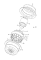
- FIG. 1 is an exploded perspective view of the electric motor according to the first embodiment.
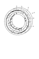
- FIG. 2 is a perspective view of the stator of the motor according to the first embodiment.
- the motor is an inner rotor type induction motor.
- the electric motor 20 includes an annular stator 1, a rotor 2 installed inside the stator 1, a bearing 3 fitted to the shaft of the rotor 2, a frame 4 and a bracket 5 for supporting the bearing 3. Be prepared.
- the stator 1 and the rotor 2 are housed in the outer shell formed by the frame 4 and the bracket 5.
- the stator 1 includes a stator core 6 to which the teeth portion 10 and the outer ring yoke portion 9 are assembled, an insulating resin 8 attached to the teeth portions 10 from both sides in the axial direction, an inner diameter side coil 7a, and an outer diameter side coil 7b. And have.
- the outer ring yoke portion 9 and the teeth portion 10 are formed by laminating a plurality of electrical steel sheets.
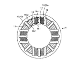
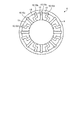
- FIG. 3 is a plan view of the stator core of the motor according to the first embodiment.
- the teeth portion 10 has a first teeth portion 10a having a connecting portion 91 with the outer ring yoke portion 9 on radiation passing through the center O of the outer ring yoke portion 9 and the center Ca of the width at the tip of the teeth. Further, in the teeth portion 10, the connecting portion 91 with the outer ring yoke portion 9 is first than the intersection D between the radiation passing through the center O of the outer ring yoke portion 9 and the center Cb of the width at the tip of the teeth and the outer ring yoke portion 9. It has a second tooth portion 10b located near the tooth portion 10a of the above.
- the teeth portion 10 has a third teeth portion 10c having a connecting portion 91 with the outer ring yoke portion 9 on radiation passing through the center O of the outer ring yoke portion 9 and the center Cc of the width at the tip of the teeth.
- the connecting portion 91 with the outer ring yoke portion 9 is third than the intersection E between the radiation passing through the center O of the outer ring yoke portion 9 and the center Cd of the width at the tip of the teeth and the outer ring yoke portion 9. It has a fourth teeth portion 10d that is separated from the teeth portion 10c of the above.
- the teeth portion 10 is the first teeth portion 10a, the second teeth portion 10b arranged next to the first teeth portion 10a, and the third teeth portion 10b arranged next to the second teeth portion 10b. It includes a teeth portion 10c and a fourth teeth portion 10d arranged next to the third teeth portion 10c.
- the distance L1 between the connecting portion 91 of the second teeth portion 10b and the first teeth portion 10a is shorter than the distance between the intersection D and the first teeth portion 10a.
- the distance L3 between the connecting portion 91 of the fourth teeth portion 10d and the third teeth portion 10c is longer than the distance L4 between the intersection E and the third teeth portion 10c.
- the first teeth portion 10a, the second teeth portion 10b, the third teeth portion 10c, and the fourth teeth portion 10d are periodically arranged in this order.
- the connecting portion 91 of the second tooth portion 10b and the fourth tooth portion 10d on both sides thereof with the outer ring yoke portion 9 is the outer ring yoke portion 9. It is located closer to the first teeth portion 10a than the intersections D and E of the radiation passing through the center Cb and Cd of the width at the center O and the tip of the teeth and the outer ring yoke portion 9.
- the connecting portion 91 of the second tooth portion 10b and the fourth tooth portion 10d on both sides thereof with the outer ring yoke portion 9 is the center O of the outer ring yoke portion 9. And, it is far from the third tooth portion 10c from the intersections D and E of the radiation passing through the central Cb and Cd of the width at the tip of the tooth and the outer ring yoke portion 9.
- FIG. 4 is a diagram showing the shape of the slot of the stator core of the motor according to the first embodiment.
- the size is different between the first slot 12, which is the slot on both sides of the first tooth portion 10a, and the second slot 13, which is the slot on both sides of the third tooth portion 10c.
- the first slots 12 on both sides of the first teeth portion 10a are line-symmetrical to each other, and the second slots 13 on both sides of the third teeth portion 10c are line-symmetrical to each other. be.
- the width Wo2 of the second slot 13 is larger than the width Wo1 of the first slot 12 on the root side of the teeth portion 10.
- the width Wi2 of the second slot 13 is smaller than the width Wi1 of the first slot 12 on the tip end side of the teeth portion 10.
- FIG. 5 is a diagram showing the shape of the coil of the electric motor according to the first embodiment.
- the inner diameter side coil 7a and the outer diameter side coil 7b are shown one by one, and the other inner diameter side coil 7a and the outer diameter side coil 7b are not shown.
- the inner diameter side coil 7a is arranged in the first slot 12. Since the inner diameter side coil 7a straddles the second slot 13, the portion of the second slot 13 near the slot open is closed by the inner diameter side coil 7a.
- the outer diameter side coil 7b is arranged in the second slot 13 so as to straddle the first slot 12.
- the inner diameter side coil 7a is arranged near the slot open of the first slot 12, and the outer diameter side coil 7b is located in the second slot 13 closer to the outer ring yoke portion 9 than the inner diameter side coil 7a. Have been placed.
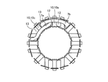
- FIG. 6 is a diagram showing a stator core in which the inner diameter side coil of the motor according to the first embodiment is arranged.
- the width of the second slot 13 in which the portion close to the slot open is closed by the inner diameter side coil 7a is narrow in the portion close to the slot open, and wide in the portion close to the outer ring yoke portion 9. Therefore, in the second slot 13, a large space for arranging the outer diameter side coil 7b can be secured as compared with the slot of the stator core in which all the teeth portions are arranged radially, and the inner diameter side coil 7a can be secured. And the outer diameter side coil 7b can be prevented from interfering with each other.
- FIG. 7 is a perspective view of the teeth portion, the inner diameter side coil, and the outer diameter side coil of the electric motor according to the first embodiment. Since the rotor 2 is not arranged inside the stator 1 before the teeth portion 10 is assembled to the outer ring yoke portion 9, the teeth portion 10 is held when the outer ring yoke portion 9 and the teeth portion 10 are assembled. The jig can be arranged inside the teeth portion 10. Therefore, the assembly accuracy of the stator core 6 can be improved and electromagnetic noise can be suppressed. Further, in the electric motor 20 according to the first embodiment, since the slot open of the first slot 12 and the slot open of the second slot 13 are arranged at equal intervals, it is possible to suppress an increase in electromagnetic noise.
- FIG. 8 is a diagram showing a stator core of an electric motor according to a modified example of the first embodiment.
- the second teeth portion 10b and the fourth teeth portion 10d are different from the stator core 6 of the motor 20 according to the first embodiment in that they have a crank shape. Since the second teeth portion 10b and the fourth teeth portion 10d are crank-shaped, the difference between the width of the first slot 12 and the width of the second slot 13 is the portion close to the slot open and the outer ring yoke portion 9. It is larger in both parts close to. Therefore, a large space for arranging the outer diameter side coil 7b can be secured in the second slot 13, and the output of the electric motor 20 can be increased.
- FIG. 9 is a rear view of a ventilation fan equipped with a motor according to the first embodiment.
- the electric motor 20 according to the first embodiment is used as a power source for rotating the fan 101 of the ventilation fan 100.
- the electric motor 20 By using the electric motor 20 as the power source for rotating the fan 101 of the ventilation fan 100, it is possible to increase the air volume and the wind pressure and reduce the noise.
- the ventilation fan 100 provided with the electric motor 20 has been described here, the electric motor 20 is not limited to the ventilation fan 100 and can be used for all blower devices such as a blower and a circulator.
- the configuration shown in the above embodiment is an example of the content, can be combined with another known technique, and a part of the configuration is omitted or changed without departing from the gist. It is also possible.
- stator 1 stator, 2 rotor, 3 bearing, 4 frame, 5 bracket, 6 stator core, 7a inner diameter side coil, 7b outer diameter side coil, 8 insulation resin, 9 outer ring yoke part, 10 teeth part, 10a first Teeth part, 10b second teas part, 10c third teas part, 10d fourth teeth part, 12 first slot, 13 second slot, 20 electric motor, 91 connection part, 100 ventilation fan, 101 fan.
Landscapes
- Engineering & Computer Science (AREA)
- Power Engineering (AREA)
- Iron Core Of Rotating Electric Machines (AREA)
Priority Applications (2)
| Application Number | Priority Date | Filing Date | Title |
|---|---|---|---|
| PCT/JP2020/022509 WO2021250735A1 (ja) | 2020-06-08 | 2020-06-08 | 電動機及び送風装置 |
| JP2022530361A JPWO2021250735A1 (https=) | 2020-06-08 | 2020-06-08 |
Applications Claiming Priority (1)
| Application Number | Priority Date | Filing Date | Title |
|---|---|---|---|
| PCT/JP2020/022509 WO2021250735A1 (ja) | 2020-06-08 | 2020-06-08 | 電動機及び送風装置 |
Publications (1)
| Publication Number | Publication Date |
|---|---|
| WO2021250735A1 true WO2021250735A1 (ja) | 2021-12-16 |
Family
ID=78847027
Family Applications (1)
| Application Number | Title | Priority Date | Filing Date |
|---|---|---|---|
| PCT/JP2020/022509 Ceased WO2021250735A1 (ja) | 2020-06-08 | 2020-06-08 | 電動機及び送風装置 |
Country Status (2)
| Country | Link |
|---|---|
| JP (1) | JPWO2021250735A1 (https=) |
| WO (1) | WO2021250735A1 (https=) |
Citations (3)
| Publication number | Priority date | Publication date | Assignee | Title |
|---|---|---|---|---|
| JPH06205557A (ja) * | 1992-12-28 | 1994-07-22 | Toshiba Corp | 回転電機の固定子 |
| JPH06217476A (ja) * | 1993-01-13 | 1994-08-05 | Toshiba Corp | 回転電機の固定子 |
| JP2002176737A (ja) * | 2000-12-07 | 2002-06-21 | Matsushita Electric Ind Co Ltd | 電動機およびそれを用いた機器 |
-
2020
- 2020-06-08 JP JP2022530361A patent/JPWO2021250735A1/ja active Pending
- 2020-06-08 WO PCT/JP2020/022509 patent/WO2021250735A1/ja not_active Ceased
Patent Citations (3)
| Publication number | Priority date | Publication date | Assignee | Title |
|---|---|---|---|---|
| JPH06205557A (ja) * | 1992-12-28 | 1994-07-22 | Toshiba Corp | 回転電機の固定子 |
| JPH06217476A (ja) * | 1993-01-13 | 1994-08-05 | Toshiba Corp | 回転電機の固定子 |
| JP2002176737A (ja) * | 2000-12-07 | 2002-06-21 | Matsushita Electric Ind Co Ltd | 電動機およびそれを用いた機器 |
Also Published As
| Publication number | Publication date |
|---|---|
| JPWO2021250735A1 (https=) | 2021-12-16 |
Similar Documents
| Publication | Publication Date | Title |
|---|---|---|
| CN103457364B (zh) | 定子及其制造方法、电机 | |
| CN101783534B (zh) | 电动机 | |
| CN102111037B (zh) | 电机 | |
| JP6343127B2 (ja) | モータ | |
| US20120299405A1 (en) | Electric motor | |
| JP5418837B2 (ja) | 積層巻きコア及びこれを備えた回転子、回転電機 | |
| JP2011024291A (ja) | ステータコア及びアキシャルギャップモータ | |
| JPWO2015140970A1 (ja) | 回転電機及び回転電機の製造方法 | |
| WO2008075667A1 (ja) | 小型モータ | |
| CN218678565U (zh) | 外转子电机 | |
| JP7466495B2 (ja) | 電動機、送風装置及び電動機の製造方法 | |
| JP2010011706A (ja) | モータ | |
| WO2014155914A1 (ja) | 回転電機 | |
| WO2021250735A1 (ja) | 電動機及び送風装置 | |
| US11005333B2 (en) | Electric motor having a stator with a radially outside rotor with the rotor having a fan mounting portion comprising a noncontact region and a contract region configured to contact a mouting surface of a fan | |
| JP2023171054A (ja) | 回転電機 | |
| KR20140010562A (ko) | 고정 마그넷을 갖는 액시얼 갭형 모터 | |
| JP2006254561A (ja) | 回転電機 | |
| JP5773498B2 (ja) | モーターステータ | |
| CN115995906A (zh) | 马达 | |
| JP5617566B2 (ja) | 回転電機と回転電機の固定子 | |
| JP7085853B2 (ja) | 回転電機、回転電機の製造方法、および送風機 | |
| JP4386909B2 (ja) | モータ | |
| JP2009296745A (ja) | 多極アキシャルギャップ型コンデンサ電動機とその製造方法 | |
| WO2021079777A1 (ja) | インシュレータ、モータ、送風機および空気調和機 |
Legal Events
| Date | Code | Title | Description |
|---|---|---|---|
| 121 | Ep: the epo has been informed by wipo that ep was designated in this application |
Ref document number: 20940177 Country of ref document: EP Kind code of ref document: A1 |
|
| ENP | Entry into the national phase |
Ref document number: 2022530361 Country of ref document: JP Kind code of ref document: A |
|
| NENP | Non-entry into the national phase |
Ref country code: DE |
|
| 122 | Ep: pct application non-entry in european phase |
Ref document number: 20940177 Country of ref document: EP Kind code of ref document: A1 |