WO2021246232A1 - 車両用表示装置 - Google Patents
車両用表示装置 Download PDFInfo
- Publication number
- WO2021246232A1 WO2021246232A1 PCT/JP2021/019708 JP2021019708W WO2021246232A1 WO 2021246232 A1 WO2021246232 A1 WO 2021246232A1 JP 2021019708 W JP2021019708 W JP 2021019708W WO 2021246232 A1 WO2021246232 A1 WO 2021246232A1
- Authority
- WO
- WIPO (PCT)
- Prior art keywords
- image
- image display
- display means
- liquid crystal
- light
- Prior art date
- Legal status (The legal status is an assumption and is not a legal conclusion. Google has not performed a legal analysis and makes no representation as to the accuracy of the status listed.)
- Ceased
Links
Images



Classifications
-
- B—PERFORMING OPERATIONS; TRANSPORTING
- B60—VEHICLES IN GENERAL
- B60K—ARRANGEMENT OR MOUNTING OF PROPULSION UNITS OR OF TRANSMISSIONS IN VEHICLES; ARRANGEMENT OR MOUNTING OF PLURAL DIVERSE PRIME-MOVERS IN VEHICLES; AUXILIARY DRIVES FOR VEHICLES; INSTRUMENTATION OR DASHBOARDS FOR VEHICLES; ARRANGEMENTS IN CONNECTION WITH COOLING, AIR INTAKE, GAS EXHAUST OR FUEL SUPPLY OF PROPULSION UNITS IN VEHICLES
- B60K35/00—Instruments specially adapted for vehicles; Arrangement of instruments in or on vehicles
- B60K35/20—Output arrangements, i.e. from vehicle to user, associated with vehicle functions or specially adapted therefor
- B60K35/21—Output arrangements, i.e. from vehicle to user, associated with vehicle functions or specially adapted therefor using visual output, e.g. blinking lights or matrix displays
- B60K35/22—Display screens
-
- B—PERFORMING OPERATIONS; TRANSPORTING
- B60—VEHICLES IN GENERAL
- B60K—ARRANGEMENT OR MOUNTING OF PROPULSION UNITS OR OF TRANSMISSIONS IN VEHICLES; ARRANGEMENT OR MOUNTING OF PLURAL DIVERSE PRIME-MOVERS IN VEHICLES; AUXILIARY DRIVES FOR VEHICLES; INSTRUMENTATION OR DASHBOARDS FOR VEHICLES; ARRANGEMENTS IN CONNECTION WITH COOLING, AIR INTAKE, GAS EXHAUST OR FUEL SUPPLY OF PROPULSION UNITS IN VEHICLES
- B60K35/00—Instruments specially adapted for vehicles; Arrangement of instruments in or on vehicles
- B60K35/20—Output arrangements, i.e. from vehicle to user, associated with vehicle functions or specially adapted therefor
- B60K35/21—Output arrangements, i.e. from vehicle to user, associated with vehicle functions or specially adapted therefor using visual output, e.g. blinking lights or matrix displays
- B60K35/23—Head-up displays [HUD]
-
- B—PERFORMING OPERATIONS; TRANSPORTING
- B60—VEHICLES IN GENERAL
- B60K—ARRANGEMENT OR MOUNTING OF PROPULSION UNITS OR OF TRANSMISSIONS IN VEHICLES; ARRANGEMENT OR MOUNTING OF PLURAL DIVERSE PRIME-MOVERS IN VEHICLES; AUXILIARY DRIVES FOR VEHICLES; INSTRUMENTATION OR DASHBOARDS FOR VEHICLES; ARRANGEMENTS IN CONNECTION WITH COOLING, AIR INTAKE, GAS EXHAUST OR FUEL SUPPLY OF PROPULSION UNITS IN VEHICLES
- B60K35/00—Instruments specially adapted for vehicles; Arrangement of instruments in or on vehicles
- B60K35/60—Instruments characterised by their location or relative disposition in or on vehicles
-
- B—PERFORMING OPERATIONS; TRANSPORTING
- B60—VEHICLES IN GENERAL
- B60K—ARRANGEMENT OR MOUNTING OF PROPULSION UNITS OR OF TRANSMISSIONS IN VEHICLES; ARRANGEMENT OR MOUNTING OF PLURAL DIVERSE PRIME-MOVERS IN VEHICLES; AUXILIARY DRIVES FOR VEHICLES; INSTRUMENTATION OR DASHBOARDS FOR VEHICLES; ARRANGEMENTS IN CONNECTION WITH COOLING, AIR INTAKE, GAS EXHAUST OR FUEL SUPPLY OF PROPULSION UNITS IN VEHICLES
- B60K35/00—Instruments specially adapted for vehicles; Arrangement of instruments in or on vehicles
- B60K35/80—Arrangements for controlling instruments
- B60K35/81—Arrangements for controlling instruments for controlling displays
-
- G—PHYSICS
- G02—OPTICS
- G02B—OPTICAL ELEMENTS, SYSTEMS OR APPARATUS
- G02B27/00—Optical systems or apparatus not provided for by any of the groups G02B1/00 - G02B26/00, G02B30/00
- G02B27/01—Head-up displays
-
- G—PHYSICS
- G09—EDUCATION; CRYPTOGRAPHY; DISPLAY; ADVERTISING; SEALS
- G09G—ARRANGEMENTS OR CIRCUITS FOR CONTROL OF INDICATING DEVICES USING STATIC MEANS TO PRESENT VARIABLE INFORMATION
- G09G5/00—Control arrangements or circuits for visual indicators common to cathode-ray tube indicators and other visual indicators
Definitions
- the present invention relates to a display device installed in a vehicle such as an automobile, and particularly to a head-up display device (hereinafter referred to as a HUD device).
- a HUD device a head-up display device
- a HUD device As a HUD device, a device has been proposed in which light constituting an image is projected on the windshield of an automobile so that a occupant such as a driver can visually recognize a virtual image of the image by the reflected light. It should be noted that making the virtual image visible thereafter is also referred to as displaying an image. Further, a HUD device capable of displaying a plurality of images with one HUD device has also been proposed. For example, Patent Documents 1 and 2 propose a HUD device having two image display units, each of which is composed of a liquid crystal display or the like, and having a configuration in which a plurality of images displayed on the image display units are displayed. ..
- a half mirror is arranged between two image display units, the half mirror reflects the image light of one image display unit, and the image of the other image display unit is used.
- the structure is such that light is transmitted and these image lights are projected onto the front glass by the optical system of the HUD device.
- Patent Document 1 is a technique for displaying two images at different positions at the same time so as to give an image with a sense of depth. However, when the two images are visually recognized overlapping with each other when viewed from the occupant, each image is clearly recognized. It can be difficult to do.
- Patent Document 2 is a technique for displaying two images with different inclinations so as to give an image with a three-dimensional effect. In this case as well, each image is clearly recognized for a portion where the two images overlap. Can be difficult.
- both Patent Documents 1 and 2 use a liquid crystal panel (liquid crystal display) as an image display unit, and the two displayed images are both composed of images displayed on the liquid crystal panel. Therefore, when it is desired to give specificity to the display of two images, for example, in order to display one image as a main image and the other as a sub image, the sharpness, brightness, contrast, etc. of the two images are different. It is difficult to display an image with a high display effect.
- liquid crystal panel liquid crystal display
- An object of the present invention is to provide a display device for a vehicle including a HUD device having a high display effect in which a displayed image can be clearly recognized and a plurality of images have specificity.
- the present invention includes an image display unit for displaying an image on an image display surface, and an optical system for projecting the image light of the displayed image onto a windshield of a vehicle, and the light reflected by the windshield is used to display an image. It is a display device for vehicles that makes it possible to visually recognize an imaginary image.
- the image display unit includes a first image display means and a second image display means, and an optical system transmits the image light of the first image display means to provide a second image.
- a half mirror that reflects the image light of the display means is provided.
- a display control means for independently controlling the image display of the first image display means and the second image display means is provided.
- the display control means exclusively displays the first image display means and the second image display means, or simultaneously displays the first image display means and the second image display means. Further, in the present invention, it is preferable that the image display surfaces of the first image display means and the second image display means are inclined at different angles with respect to the emission direction of the respective image lights. Further, it is preferable that the image display surfaces of the first image display means and the second image display means have the same or different distances to the half mirror.
- the image display unit further includes a third image display means
- the optical system further includes a second half mirror.
- the second half mirror transmits one of the image light of the first image display means and the second image display means and the image light of the third image display means, and reflects the other.
- the display control means makes one or two image display means of the first image display means, the second image display means, and the third image display means exclusive to the other image display means, or the first. It is preferable that one image display means, the second image display means, and the third image display means simultaneously display images.
- the image display means in the present invention is preferably composed of any one of a liquid crystal display device, a DMD, a mask display device, an organic EL device, or a combination thereof.
- a plurality of image display means can be selectively or all displayed, and virtual images of these displayed images can be visually recognized through the windshield, so that a desired image can be selectively selected.
- a vehicle display device capable of displaying the displayed image and clearly recognizing the displayed image is provided. Further, by configuring a plurality of image display means with a combination of a liquid crystal device, a DMD, a mask display device, and an organic EL device, a vehicle display device having a high display effect utilizing the peculiarity of display in each device is provided. ..
- FIG. The conceptual block diagram of the HUD apparatus of Embodiment 1.
- FIG. The schematic block diagram which saw the HUD apparatus of Embodiment 1 from the side direction.
- FIG. The schematic perspective view explaining the display operation of Embodiment 1.
- FIG. The simplified perspective view explaining the display form of Embodiment 1.
- FIG. The block diagram of the specific example of the HUD apparatus of Embodiment 2.
- the block diagram of the specific example of the HUD apparatus of Embodiment The block diagram of the specific example of the HUD apparatus of Embodiment 3.
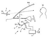
- FIG. 1 is a conceptual configuration diagram of the HUD device 1 of the first embodiment applied to an automobile.
- the HUD device 1 is arranged in the dashboard DB of the automobile, and the image light L emitted from the HUD device 1 is projected onto the windshield (referred to as a windshield) WS of the automobile through the upper surface opening H of the dashboard.
- the projected image light L is reflected by the windshield WS and directed to the occupant M such as the driver of the automobile.
- the image light L enters the eyes of the occupant M, the occupant M can visually recognize the virtual image I by the image light at the front position of the automobile through the windshield WS, and the image is displayed.
- the HUD device 1 includes an image display unit 2 that displays the generated image on the image display surface, and an optical system 3 that projects the image displayed on the image display unit 2 onto the windshield WS.
- the image display unit 2 is composed of two first image display means 21 and a second image display means 22 that independently display images.
- the optical system 3 is adapted to project the image lights L1 and L2 of the images displayed by these two image display means 21 and 22 onto the windshield WS, respectively.
- the two image lights L1 and L2 reflected by the windshield enter the eyes of the occupant M, respectively, and the occupant M can visually recognize the two virtual images, that is, the first virtual image I1 and the second virtual image I2. It will be possible.
- the central axis of the optical path of the image light L is the main optical axis of the optical system 3.
- FIG. 2 shows a schematic configuration diagram of the HUD device 1 as viewed from the side surface direction.
- the first image display means 21 and the second image display means 22 are each composed of a liquid crystal device provided with a liquid crystal panel, and are configured as a first liquid crystal device 21 and a second liquid crystal device 22.
- the first liquid crystal device 21 is configured to display the first image on the liquid crystal panel and to emit the first image light L1 of the displayed first image.
- the second liquid crystal device 22 is configured to display the second image on the liquid crystal panel and to emit the second image light L2 of the displayed second image.
- the postures of the first image light L1 and the second image light L1 are set so as to intersect at a predetermined position.
- the optical system 3 is arranged at a position where the first image light L1 and the second image light L2 intersect, and is a half mirror 30 that transmits the first image light L1 and reflects the second image light L2, and the half mirror 30. It is provided with a first reflecting unit 31 that reflects the image light transmitted or reflected by the first reflecting unit 31, and a second reflecting unit 32 that further reflects the light reflected by the first reflecting unit 31 and projects it onto the windshield WS.
- the surface angles with respect to the first liquid crystal device 21 and the second liquid crystal device 22 are set so that the optical paths of the transmitted first image light L1 and the reflected second image light L2 are directed in the same direction. ing.
- the first reflecting unit 31 is composed of a convex mirror or a plane mirror, but here it is composed of a plane mirror 31.
- the second reflecting portion 32 is composed of a concave mirror, and the concave mirror 32 is composed of a spherical surface or an aspherical surface having a curvature that is a required focal length.
- the plane mirror 31 is provided to substantially extend the focal length of the concave mirror 32. Then, by configuring the HUD device 1 so that the image displayed on the image display unit 2 is arranged within the focal length of the concave mirror 32, each image displayed on the first liquid crystal device 21 and the second liquid crystal device 22 is displayed.
- the first virtual image I1 and the second virtual image I2 can be visually recognized by the occupant M.
- first liquid crystal device 21 and the second liquid crystal device 22 are connected to the display control device 4, and the image display on each of the liquid crystal devices 21 and 22 is controlled by the display control device 4.
- a setting unit 5 is connected to the display control device 4, and the first liquid crystal device 21 and the second liquid crystal device 22 are individually displayed and controlled by the setting unit 5 by the occupant M or the like, or both.
- the liquid crystal devices 21 and 22 are configured to be able to control the display of images at the same time.
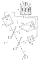
- FIG. 3 is a diagram showing a specific configuration of the HUD device 1.
- the first liquid crystal device 21 of the image display unit 2 includes a case 210 that also serves as a heat sink, and a liquid crystal panel 211 capable of displaying the first image is arranged in the opening of the case 210.
- a liquid crystal panel 211 capable of displaying the first image is arranged in the opening of the case 210.
- it is composed of a liquid crystal panel that displays a color image.
- a light source substrate 213 on which an LED (light emitting diode) 212 for a backlight is mounted is arranged on the inner bottom surface of the case 210.
- the LED 212 is arranged so that the light emitting surface faces the liquid crystal panel 211, and the light emitted from the LED 212 is reflected on the inner surface of the case 210 and condensed as a light flux, or as a parallel light beam on the liquid crystal panel 211. It is irradiated, passes through the liquid crystal panel 211, and is emitted as the first image light L1. Since the liquid crystal panel 211 is oriented in a direction orthogonal to the central axis of the light flux of the first image light L1, that is, the first optical axis, the first image is a planar image perpendicular to the first optical axis. It will be displayed. Further, the center of the liquid crystal panel 211 is substantially aligned with the first optical axis.
- the second liquid crystal device 22 has the same configuration, and the case 220 is provided with a liquid crystal panel 221 capable of displaying a second image of a color image.
- the light emitted from the LED 222 mounted on the substrate 223 irradiates the liquid crystal panel 221, passes through the liquid crystal panel 221 and is emitted as the second image light L2.
- the image display surface displaying the second image is directed in a direction inclined at a required angle with respect to the second optical axis which is the central axis of the light flux of the second image light L2 emitted from the LED 222. ing. Therefore, the second image is displayed as a planar image inclined at an angle with respect to the second optical axis. Further, the center of the liquid crystal panel 221 is substantially aligned with the second optical axis.
- a mirror is arranged between the liquid crystal panel 211 and the LED 212, and the light of the LED 212 is reflected by the mirror to irradiate the liquid crystal panel 211. May be good. By doing so, the relative positional relationship between the liquid crystal panel 211 and the LED 212 is changed, and the degree of freedom in designing the shape of the case 210 is improved. The same applies to the second liquid crystal device 22.
- the distances from the liquid crystal panels 211 and 221 which are the image display surfaces on which the respective images are displayed to the half mirror 30 may be arbitrarily set. However, here, the distance between the two is almost equal. That is, the distance from the liquid crystal panel 211 of the first liquid crystal device 21 to the half mirror 30 is equal to the distance from the liquid crystal panel 221 of the second liquid crystal device 22 to the half mirror 30.
- the display control device 4 includes a first control unit 41 that controls the image display of the first liquid crystal device 21, and a second control unit 42 that controls the image display of the second liquid crystal device 22.
- the first control unit 41 and the second control unit 42 can arbitrarily set the image to be displayed on the first liquid crystal device 21 and the second liquid crystal device 22 by setting the occupant M or the like in the setting unit 5. It is possible. Further, by the setting in the setting unit 5, it is possible to individually control the image display in the first liquid crystal device 21 and the second liquid crystal device 22 as described above, or to control both devices 21 and 22 at the same time.
- the first image is displayed on the liquid crystal panel 211 of the first liquid crystal device 21 by the first control unit 41 of the display control device 4 based on the settings in the setting unit 5, and the LED 212 emits light.
- the liquid crystal panel 211 is irradiated with the backlight light, the light transmitted through the liquid crystal panel 211 is emitted as the first image light L1.
- the first image light L1 is projected onto the half mirror 30 and transmitted through the half mirror 30.
- the transmitted first image light L1 is reflected by the plane mirror 31 and further reflected by the concave mirror 32 and projected onto the windshield WS.
- the first image light L1 is reflected by the windshield WS and enters the eyes of the occupant M.
- the occupant M is placed in the front position of the automobile with the first virtual image I1 by the first image light. Can be visually recognized, and the first image is displayed.
- the visible first virtual image I1 is a virtual image perpendicular to the main optical axis of the optical system 3, that is, the occupant M. Observed as a vertical virtual image when viewed from.
- the first image is a speedometer image, which is composed of a speed scale and a speed numerical value, and is visually recognized as a first virtual image I1 that stands upright at a predetermined position in front of the occupant.
- the second image is displayed on the liquid crystal panel 221 of the second liquid crystal device 22 by the second control unit 42 of the display control device 4, and when the LED 222 is emitted, the second image light L2 is emitted and the second image light is emitted.
- L2 is projected onto the half mirror 30 and reflected by the half mirror 30.
- the reflected second image light L2 is reflected by the plane mirror 31, further reflected by the concave mirror 32 and projected onto the windshield WS, and the occupant M visually recognizes the second virtual image I2 by the second image light L2 at the front position of the automobile.
- the second image is displayed.
- the visible second virtual image I2 is optical as shown in FIG. 4 (b). It is observed as a virtual image tilted with respect to the main optical axis of the system 3.
- the second image is a navigation image that guides the destination of the vehicle, and is composed of an arrow image indicating the destination of the vehicle, and is horizontally at a required angle in the front-rear direction including a predetermined position in front of the occupant. It is visually recognized as a second virtual image I2 extending at an angle close to.
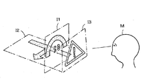
- the virtual images I1 and I2 of the first image and the second image are visually recognized at the same time.
- the speedometer image of the first virtual image I1 oriented in the vertical direction and the navigation image of the second virtual image I2 at an angle close to horizontal are simultaneously visually recognized at substantially the same position.
- both images can be displayed at the same time.
- only one of the speedometer image I1 and the navigation image I2, or both images can be displayed at the same time. Therefore, by displaying only the images required by the occupant M, it is possible to avoid displaying both images in an overlapping manner, and each image can be clearly recognized. Further, by displaying both images at the same time, the information by both images can be recognized at the same time.
- the liquid crystal panel 211 of the first liquid crystal device 21 and the liquid crystal panel 221 of the second liquid crystal device 22 are arranged at the same distance from the half mirror 30, and the first of the liquid crystal panels 211 and 221 are arranged. Since the first optical axis and the second optical axis coincide with the main optical axis, the first virtual image I1 and the second virtual image I2 are visually recognized as intersecting at substantially the center positions of each, as shown in FIG. 5A. To. In this embodiment, since the centers of the first virtual image I1 and the second virtual image I2 are aligned, the viewpoint position (focal position) when the occupant M visually recognizes both virtual images is the same, and the visibility is improved.
- the centers of the liquid crystal panel 211 of the first liquid crystal device 21 and the liquid crystal panel 221 of the second liquid crystal device 22 are configured to be displaced with respect to the first optical axis or the second optical axis. It is also good. For example, if the liquid crystal panel 211 of the first liquid crystal device 21 is displaced with respect to the first optical axis and the end portion of the liquid crystal panel 211 is positioned on the first optical axis, as shown in FIG. 5 (b). , The display form can be such that the first virtual image I1 and the second virtual image I2 do not intersect.
- the end of the liquid crystal panel 211 of the first liquid crystal device 21 is positioned on the first optical axis, and the distance between the liquid crystal panel 211 of the first liquid crystal device 21 and the half mirror 30 of the liquid crystal panel 221 of the second liquid crystal device 22. May be different from each other. In other words, the distance to the concave mirror 32 is made different. By doing so, as shown in FIG. 5C, the first virtual image I1 and the second virtual image I2 can be prevented from crossing each other, and the positions of the two virtual images can be different from each other.
- the distance from the liquid crystal panel 211 of the first liquid crystal device 21 to the half mirror 30 is shorter than the distance of the liquid crystal panel 221 of the second liquid crystal device 22, so that the first virtual image I1 is more visible to the occupant M. Visible nearby.
- the first image (first virtual image I1) and the second image (second virtual image I2) can be displayed in any form, the visibility of each image is enhanced, and each image can be clearly recognized. ..
- FIG. 6 shows a specific configuration diagram of the HUD device 1A of the second embodiment.
- the two image display means are composed of a liquid crystal display 21 as a first image display means and a DMD (digital micromirror device) device 23 as a second image display means.
- the liquid crystal device 21 has the same configuration as the first liquid crystal device 21 of the first embodiment, and is configured to be capable of displaying the first image on the liquid crystal panel 211 and emitting the first image light L1 of the displayed first image. ing.
- the DMD device 23 is mounted on a case 230, a DMD 231 provided in the case 230 and selectively driven by a micromirror under the control of the display control device 4, and light on the substrate 233. It is provided with an LED 232 that irradiates the light, a lens 234 that uses the light of the LED 232 as a parallel luminous flux, and a screen 235.
- the array surface of the micromirror is tilted at a required angle with respect to the optical axis of the lens 234 (equivalent to the second optical axis).
- the light of the LED 232 is projected onto the DMD 231, and at the same time, an image is formed on the screen 235 by selectively controlling the angle of the micromirror in the DMD 231, and the second image light L2 is generated by this image. ..
- the surface of the screen 235 on which this image is formed becomes the image display surface.
- the second image light L2 is projected onto the half mirror 30 along the second optical axis, and is reflected here toward the concave mirror 32.
- a virtual image of the first image by the liquid crystal device 21 as the first image display means and a virtual image of the second image by the DMD device 23 as the second image display means are displayed. It is possible to see it. Further, under the control of the display control device 4, either one of the first image and the second image can be selectively displayed, or both images can be displayed at the same time. Therefore, by displaying only the images required by the occupant M, it is possible to avoid displaying both images in an overlapping manner, and each image can be clearly recognized. Further, by displaying both images at the same time, the information by both images can be recognized at the same time.
- the liquid crystal display 21 and the DMD device 23 are different in the definition, brightness, contrast, etc. of the image displayed in each, the appearance of the first virtual image and the second virtual image is also different. Therefore, by properly using the liquid crystal display device and the DMD device according to the design of the image to be displayed, it is possible to perform a display utilizing the peculiarities of each, and it is possible to enhance the display effect as a whole.
- the DMD device of the second embodiment is a MEMS (micro electro mechanical system) in which electronic elements such as a circuit component for controlling a micromirror of a DMD and a circuit component for controlling light emission of an LED are integrally formed. It may be configured as a device.
- MEMS micro electro mechanical system
- FIG. 7 shows a specific configuration diagram of the HUD device 1B of the third embodiment.
- the two image display means are composed of a liquid crystal display device 21 as a first image display means and a mask display device 24 as a second image display means.
- the liquid crystal device 21 has the same configuration as the first liquid crystal device of the first embodiment, and is configured to be capable of emitting the first image light L1 of the first image.
- the mask display device 24 is mounted on a case 240, a mask 241 provided in the case 240 on which a translucent portion of a required image pattern is formed, and a substrate 243 to irradiate the mask 241 with light.
- the LED 242 and the lens 244 having the light of the LED 242 as a parallel luminous flux are provided. Since the mask display device 24 is configured to emit the image light of a required image by selectively transmitting the light emitted from the LED 242 by the mask 241, it is referred to as a mask display device here.
- the surface of the mask 241 is the image display surface.
- a virtual image of the first image by the first liquid crystal display device 21 as the first image display means and a second image by the mask display device 24 as the second image display means It is possible to visually recognize the virtual image of. Further, under the control of the display control device 4, either one of the first image and the second image can be selectively displayed, or both images can be displayed at the same time, so that each image can be clearly recognized. Become. Further, by displaying both images at the same time, the information by both images can be recognized at the same time.
- the liquid crystal device 21 and the mask display device 24 are different in the definition, brightness, contrast, etc. of the image displayed in each, the appearance of the first virtual image and the second virtual image is also different. Therefore, by properly using the liquid crystal display device and the mask display device according to the pattern of the image to be displayed, it is possible to perform the display utilizing the peculiarities of each, and it is possible to enhance the display effect as a whole.
- one or both of the two image display means may be configured by an organic EL device.
- the organic EL device can form a required image on the organic EL panel and display it, and the image light of the displayed image is emitted. Therefore, in the organic EL device, the organic EL panel serves as an image display surface as it is.
- the first image display means may be composed of any of a DMD device, a mask display device, and an organic EL device
- the second image display means may be composed of a liquid crystal device.
- both the first image display means and the second image display means may be composed of a DMD device, a mask display device, an organic EL device, or a combination thereof including a liquid crystal display device.
- FIG. 8 shows a specific configuration diagram of the HUD device 1C of the fifth embodiment.
- the image display unit 2 includes first to third image display means, and the optical system 3 includes two first and second half mirrors. That is, the image display unit 2 includes a liquid crystal display device 21 as a first image display means, a DMD device 23 as a second image display means, and a mask display device 24 as a third image display means.
- the liquid crystal device 21 has the same configuration as the first liquid crystal device 21 of the first embodiment
- the DMD device 23 is the same as the DMD device 23 of the second embodiment
- the mask display device 24 is the same as the mask display device 24 of the third embodiment. Is.
- the first half mirror 30A of the optical system 3 transmits the first image light L1 from the liquid crystal device 21 and reflects the second image light L2 from the DMD device 23.
- the second half mirror 30B transmits the first image light L1 and the second image light L2, and reflects the third image light L3 from the mask display device 24.
- the image lights L1 to L3 transmitted or reflected through the second half mirror 30B are reflected by the plane mirror 31, reflected by the concave mirror 32 not shown in the figure, and projected onto the windshield WS.
- the positional relationship between the liquid crystal device 21 and the DMD device 23 with respect to the first half mirror 30A is appropriately set. Further, the position of the second half mirror 30B with respect to the first half mirror 30A and the position of the mask display device 24 with respect to the second half mirror 30B are also appropriately set.
- the liquid crystal device 21 and the DMD device 23 are set to have substantially the same distance from the concave mirror 32, and the mask display device 24 is set to a shorter distance than that.
- the first to third image display means can display images independently by the display control device 4. That is, in the liquid crystal display 21, the DMD device 23, and the mask display device 24, the image display is controlled by the first control unit 41, the second control unit 42, and the third control unit 43 of the display control device 4, respectively. Therefore, it can be configured as a display device capable of displaying any one, two, or three images of these three devices.
- FIG. 9 is an example thereof, and as in the first embodiment, a speedometer image is displayed as the first image, a navigation image is displayed as the second image, and a warning image is displayed as the third image so that these virtual images can be visually recognized. It is composed. Since the liquid crystal display 21 and the DMD device 23 that display the first image and the second image can display an arbitrary image by control, they are applied when displaying an image that changes with time. The mask display device 24 for displaying the third image is applied when displaying a fixed image, which is advantageous in reducing the cost of the device.
- the liquid crystal device 21, the DMD device 23, and the mask display device 24 by appropriately setting the mutual positions and postures of the first and second half mirrors 30A and 30B, the liquid crystal device 21, the DMD device 23, and the mask display device 24, a virtual image of each image is shown. It becomes possible to visually recognize in the form shown in 9.
- the speedometer image and the navigation image have the same display form as in the first embodiment, and the warning image is displayed at the position closest to the occupant M.
- each virtual image can be clearly recognized. Further, by utilizing the peculiarity of the display in each device, it is possible to display with a high display effect.
- the first reflecting portion of the optical system may be a convex mirror.
- the first reflective portion may not be provided.
- the windshield in the present invention is not limited to the windshield of the automobile described in the embodiment, and may be a part of a vehicle body such as a translucent window provided in the vehicle.
- the angle between the first image and the second image with respect to the optical axis is not limited to the description of the embodiment, and can be arbitrarily set to the angle between the first image and the second image.
Landscapes
- Engineering & Computer Science (AREA)
- Chemical & Material Sciences (AREA)
- Combustion & Propulsion (AREA)
- Transportation (AREA)
- Mechanical Engineering (AREA)
- Physics & Mathematics (AREA)
- General Physics & Mathematics (AREA)
- Optics & Photonics (AREA)
- Computer Hardware Design (AREA)
- Theoretical Computer Science (AREA)
- Instrument Panels (AREA)
- Controls And Circuits For Display Device (AREA)
Abstract
表示した画像を明確に認識することが可能であり、複数の画像に特異性を持たせた表示効果の高いHUD装置を提供する。画像を表示するための画像表示部2と、表示された画像の画像光を車両のウインドシールドWSに投射する光学系3を備え、ウインドシールドWSで反射された光により画像の虚像Iを視認できるようにしたHUD装置1である。画像表示部2は第1画像表示手段21と第2画像表示手段22を備え、光学系3は第1画像光L1を透過し第2画像光をL2反射するハーフミラー30を備える。さらに、第1画像表示手段21と第2画像表示手段22を独立して制御する表示制御手段4を備える。
Description
本発明は自動車等の車両に装備される表示装置に関し、特にヘッドアップディスプレイ装置(以下、HUD装置)に関する。
HUD装置として、自動車のフロントガラスに画像を構成する光を投射し、その反射光により運転者等の乗員が当該画像の虚像を視認できるようにしたものが提案されている。なお、以降において虚像を視認できるようにすることを、画像を表示するとも言う。また、1つのHUD装置で複数の画像を表示できるようにしたHUD装置も提案されている。例えば、特許文献1,2には、それぞれ液晶ディスプレイ等で構成された2つの画像表示部を備え、これら画像表示部に表示された複数の画像をそれぞれ表示する構成のHUD装置が提案されている。
これら特許文献1,2の技術は、いずれも2つの画像表示部の間にハーフミラーを配設し、当該ハーフミラーで一方の画像表示部の画像光を反射し、他方の画像表示部の画像光を透過させ、これらの画像光をHUD装置の光学系によりフロントガラスに投射させる構成がとられている。
特許文献1は奥行感のある画像となるように、2つの画像を異なる位置に同時に表示する技術であるが、乗員から見て2つの画像が重なって視認されると、各画像を明確に認識することが難しいことがある。特許文献2は立体感のある画像となるように、2つの画像を異なる傾きで表示する技術であるが、この場合にも2つの画像が重なっている部分については各画像を明確に認識することが難しいことがある。
また、特許文献1,2はいずれも画像表示部として液晶パネル(液晶ディスプレイ)を用いており、表示される2つの画像はいずれも液晶パネルに表示された画像で構成される。そのため、2つの画像の表示に特異性を持たせたい場合、例えば一方の画像をメイン画像とし、他方をサブ画像として表示させるために、2つの画像の鮮鋭度、明るさ、コントラスト等を相違させることが難しく、表示効果の高い画像を表示することが難しい。
本発明の目的は、表示した画像を明確に認識することが可能であり、また複数の画像に特異性を持たせた表示効果の高いHUD装置を含む車両用表示装置を提供する。
本発明は、画像表示面に画像を表示するための画像表示部と、表示された画像の画像光を車両のウインドシールドに投射する光学系を備え、当該ウインドシールドで反射された光により画像の虚像を視認できるようにした車両用表示装置であって、画像表示部は第1画像表示手段と第2画像表示手段を備え、光学系は第1画像表示手段の画像光を透過し第2画像表示手段の画像光を反射するハーフミラーを備える。さらに、第1画像表示手段と第2画像表示手段の画像表示を独立して制御する表示制御手段を備える。
本発明において、表示制御手段は第1画像表示手段と第2画像表示手段を排他的に、又は第1画像表示手段と第2画像表示手段を同時に画像表示する。また、本発明において、第1画像表示手段と第2画像表示手段の各画像表示面はそれぞれの画像光の出射方向に対して異なる角度で傾斜されることが好ましい。さらに、第1画像表示手段と第2画像表示手段の画像表示面はハーフミラーまでの距離が同じ又は相違されることが好ましい。
本発明は、さらに画像表示部は第3画像表示手段を備え、光学系はさらに第2のハーフミラーを備える。第2のハーフミラーは第1画像表示手段と第2画像表示手段の画像光と、第3画像表示手段の画像光の一方を透過し、他方を反射する。その上で、表示制御手段は、第1画像表示手段と第2画像表示手段と第3画像表示手段の1つまたは2つの画像表示手段を他の画像表示手段に対して排他的に、又は第1画像表示手段と第2画像表示手段と第3画像表示手段を同時に画像表示する構成とすることが好ましい。
本発明における画像表示手段は、液晶装置、DMD、マスク表示装置、有機EL装置のいずれか又はこれらの組み合わせで構成されることが好ましい。
本発明によれば、複数の画像表示手段を選択的にあるいは全てを表示させ、ウインドシールドを透してこれらの表示された画像の虚像を視認することができるので、所望とする画像を選択的に表示することが可能であり、表示された画像を明確に認識することが可能な車両用表示装置が提供される。また、複数の画像表示手段を液晶装置、DMD、マスク表示装置、有機EL装置の組み合わせで構成することにより、各装置における表示の特異性を活かした表示効果の高い車両用表示装置が提供される。
(実施形態1)
次に、本発明の実施の形態について図面を参照して説明する。図1は自動車に適用した実施形態1のHUD装置1の概念構成図である。自動車のダッシュボードDB内にHUD装置1が配設されており、当該HUD装置1から出射した画像光Lを、当該ダッシュボードの上面開口Hを通して自動車のフロントガラス(ウインドシールドと称する)WSに投射させる。投射された画像光LはウインドシールドWSで反射されて自動車の運転者等の乗員Mに向けられる。この画像光Lが乗員Mの眼に入ることにより、当該乗員MはウインドシールドWSを透して自動車の前方位置に画像光による虚像Iを視認することができ、当該画像の表示が行われる。
次に、本発明の実施の形態について図面を参照して説明する。図1は自動車に適用した実施形態1のHUD装置1の概念構成図である。自動車のダッシュボードDB内にHUD装置1が配設されており、当該HUD装置1から出射した画像光Lを、当該ダッシュボードの上面開口Hを通して自動車のフロントガラス(ウインドシールドと称する)WSに投射させる。投射された画像光LはウインドシールドWSで反射されて自動車の運転者等の乗員Mに向けられる。この画像光Lが乗員Mの眼に入ることにより、当該乗員MはウインドシールドWSを透して自動車の前方位置に画像光による虚像Iを視認することができ、当該画像の表示が行われる。
前記HUD装置1は、生成した画像を画像表示面に表示する画像表示部2と、この画像表示部2に表示された画像をウインドシールドWSに投射する光学系3を備えている。この画像表示部2はそれぞれ独立して画像を表示する2つの第1画像表示手段21と第2画像表示手段22で構成されている。また、光学系3はこれら2つの画像表示手段21,22で表示された画像の画像光L1,L2をそれぞれウインドシールドWSに投射させるようになっている。これにより、ウインドシールドにおいて反射された2つの画像光L1,L2がそれぞれ乗員Mの眼に入ることになり、乗員Mは2つの虚像、すなわち第1虚像I1と第2虚像I2を視認することが可能になる。なお、この画像光Lの光路の中心軸は光学系3の主光軸となる。
図2に前記HUD装置1を側面方向から見た模式構成図を示す。前記第1画像表示手段21と第2画像表示手段22はそれぞれ液晶パネルを備えた液晶装置で構成されており、第1液晶装置21と第2液晶装置22として構成されている。これらの詳細については後述するが、第1液晶装置21は液晶パネルに第1画像を表示し、表示した第1画像の第1画像光L1を出射することが可能に構成されている。同様に、第2液晶装置22は液晶パネルに第2画像を表示し、表示した第2画像の第2画像光L2を出射することが可能に構成されている。これら第1画像光L1と第2画像光L1は所定の位置で交差するようにそれぞれの姿勢が設定されている。
前記光学系3は、第1画像光L1と第2画像光L2が交差する位置に配置されて第1画像光L1を透過し第2画像光L2を反射するハーフミラー30と、このハーフミラー30で透過又は反射された画像光を反射する第1反射部31と、この第1反射部31で反射された光を更に反射してウインドシールドWSに投射する第2反射部32を備えている。このハーフミラー30は透過された第1画像光L1と、反射された第2画像光L2の光路が同一方向に向けられるように第1液晶装置21と第2液晶装置22に対する面角度が設定されている。
前記第1反射部31は凸面鏡又は平面鏡で構成されるが、ここでは平面鏡31で構成されている。第2反射部32は凹面鏡で構成されており、この凹面鏡32は所要の焦点距離となる曲率の球面または非球面で構成されている。前記平面鏡31は凹面鏡32の焦点距離を実質的に延長させるために設けられている。そして、画像表示部2において表示された画像が凹面鏡32の焦点距離内に配置されるようにHUD装置1を構成することにより、第1液晶装置21と第2液晶装置22で表示された各画像による第1虚像I1と第2虚像I2を乗員Mが視認することができる。
また、これら第1液晶装置21と第2液晶装置22は表示制御装置4に接続されており、この表示制御装置4によって各液晶装置21,22での画像表示が制御される。この表示制御装置4には設定部5が接続されており、乗員M等による設定部5での設定により第1液晶装置21と第2液晶装置22をそれぞれ個別に画像を表示制御し、あるいは両液晶装置21,22において同時に画像を表示制御することができるように構成されている。
図3は前記HUD装置1の具体的な構成を示す図である。画像表示部2の第1液晶装置21はヒートシンクを兼ねたケース210を備えており、このケース210の開口部に第1画像を表示することが可能な液晶パネル211が配設されている。ここではカラー画像を表示する液晶パネルで構成されている。また、ケース210の内底面にバックライト用のLED(発光ダイオード)212を搭載した光源基板213が配設されている。このLED212は発光面が液晶パネル211に対面するように配設されており、LED212から出射された光はケース210の内面で反射されて集光された光束として、あるいは平行光束として液晶パネル211に照射され、液晶パネル211を透過して第1画像光L1として出射される。この液晶パネル211は第1画像光L1の光束中心軸、すなわち第1光軸に対して直交する方向に向けられているので、第1画像は当該第1光軸に垂直な面状の画像として表示されることになる。また、液晶パネル211の中心はほぼ第1光軸に一致されている。
第2液晶装置22も同様の構成であり、ケース220にカラー画像の第2画像を表示することが可能な液晶パネル221が配設されている。基板223に搭載されているLED222から出射された光は液晶パネル221に照射され、当該液晶パネル221を透過して第2画像光L2として出射される。しかし、この液晶パネル221は第2画像を表示する画像表示面がLED222から出射される第2画像光L2の光束中心軸である第2光軸に対して所要の角度で傾斜した方向に向けられている。したがって、第2画像は第2光軸に角度で傾斜した面状の画像として表示されることになる。また、液晶パネル221の中心はほぼ第2光軸に一致されている。
ここで、図示は省略するが、第1液晶装置21においては、液晶パネル211とLED212との間にミラーを配設し、LED212の光をミラーで反射して液晶パネル211に照射するようにしてもよい。このようにすることで、液晶パネル211とLED212の相対位置関係を変更し、ケース210の形状の設計の自由度が向上される。第2液晶装置22についても同様である。
前記した第1液晶装置21と第2液晶装置22は、それぞれの画像が表示される画像表示面となる各液晶パネル211,221から前記ハーフミラー30までの距離はそれぞれ任意に設定されてもよいが、ここでは両者の距離は略等しくされている。すなわち、第1液晶装置21の液晶パネル211からハーフミラー30までの距離と、第2液晶装置22の液晶パネル221からハーフミラー30までの距離が等しくされている。
前記表示制御装置4は、第1液晶装置21の画像表示を制御する第1制御部41と、第2液晶装置22の画像表示を制御する第2制御部42を備えている。これら第1制御部41と第2制御部42は、乗員M等が設定部5において設定を行うことにより、第1液晶装置21と第2液晶装置22において表示する画像を任意に設定することが可能とされている。また、当該設定部5での設定により、前記したように第1液晶装置21と第2液晶装置22における画像表示をそれぞれ個別に制御し、あるいは両装置21,22を同時に制御することができる。
以上の構成のHUD装置1では、設定部5での設定に基づいて表示制御装置4の第1制御部41により第1液晶装置21の液晶パネル211に第1画像が表示され、かつLED212が発光されて液晶パネル211にバックライト光が照射されると、液晶パネル211を透過した光は第1画像光L1として出射される。この第1画像光L1はハーフミラー30に投射され、当該ハーフミラー30を透過される。この透過された第1画像光L1は平面鏡31において反射され、さらに凹面鏡32において反射されてウインドシールドWSに投射される。
この第1画像光L1はウインドシールドWSで反射され、乗員Mの眼に入ることにより、図4(a)に示すように、乗員Mは自動車の前方位置に第1画像光による第1虚像I1を視認することができ、第1画像の表示が行われる。第1液晶装置21の液晶パネル211は画像表示面が第1光軸に垂直に向けられているので、視認される第1虚像I1は光学系3の主光軸に垂直な虚像、すなわち乗員Mから見て鉛直方向の虚像として観察される。この例では、第1画像はスピードメータ画像であり、速度目盛と速度数値で構成されており、乗員の前方の所定位置においてほぼ垂直に正立した第1虚像I1として視認される。
また、表示制御装置4の第2制御部42により第2液晶装置22の液晶パネル221に第2画像が表示され、LED222が発光されると第2画像光L2が出射され、この第2画像光L2はハーフミラー30に投射され、当該ハーフミラー30で反射される。この反射された第2画像光L2は平面鏡31において反射され、さらに凹面鏡32において反射されてウインドシールドWSに投射され、乗員Mは自動車の前方位置に第2画像光L2による第2虚像I2を視認することができ、第2画像の表示が行われる。
第2液晶装置22の液晶パネル221は画像表示面が第2光軸に対して所要の角度で傾斜されているので、図4(b)に示すように、視認される第2虚像I2は光学系3の主光軸に対して傾斜された虚像として観察される。この例では、第2画像は走行先を案内するナビゲーション画像であり、自動車の走行先を示す矢印画像で構成されており、乗員の前方の所定位置を含む前後方向に所要の角度で、例えば水平に近い角度で延びる第2虚像I2として視認される。
一方、表示制御装置4により第1液晶装置21と第2液晶装置22を同時に制御することにより、第1画像と第2画像の各虚像I1,I2が同時に視認される。図4(c)のように、鉛直方向に向けられた第1虚像I1のスピードメータ画像と、水平に近い角度の第2虚像I2のナビゲーション画像がほぼ同じ位置において同時に視認されるようになる。
このように、乗員Mが設定部5において設定を行うことにより、表示制御装置4の制御によって第1液晶装置21による第1画像と第2液晶装置22による第2画像のいずれか一方を選択的に表示させ、あるいは両画像を同時に表示させることができる。この例では、スピードメータ画像I1とナビゲーション画像I2のいずれか一方のみ、あるいは両画像を同時に表示させることができる。したがって、乗員Mが必要とする画像のみを表示させることにより、両画像が重なって表示されることが回避でき、各画像を明確に認識することができるようになる。また、両画像を同時に表示させることにより両画像による情報を同時に認識することができる。
ここで、実施形態1では、第1液晶装置21の液晶パネル211と第2液晶装置22の液晶パネル221がそれぞれハーフミラー30に対して同じ距離に配置され、かつ各液晶パネル211,221の第1光軸、第2光軸が主光軸に一致されているので、図5(a)のように、第1虚像I1と第2虚像I2はそれぞれのほぼ中央位置において交差する形態で視認される。この形態では、第1虚像I1と第2虚像I2の中心が一致されるので、乗員Mが両虚像を視認する際の視点位置(焦点位置)が同じになり、視認性が向上される。
一方、図示は省略するが、第1液晶装置21の液晶パネル211と第2液晶装置22の液晶パネル221の各中心を第1光軸又は第2光軸に対して変位させるように構成してもよい。例えば、第1液晶装置21の液晶パネル211を第1光軸に対して変位させ、当該液晶パネル211の端部を第1光軸に位置させるようにすれば、図5(b)のように、第1虚像I1と第2虚像I2を交差させない表示形態とすることができる。
また、第1液晶装置21の液晶パネル211の端部を第1光軸に位置させるとともに、第1液晶装置21の液晶パネル211と第2液晶装置22の液晶パネル221のハーフミラー30までの距離を互いに相違させるようにしてもよい。換言すれば凹面鏡32までの距離を相違させるようにする。このようにすれば、図5(c)のように、第1虚像I1と第2虚像I2を交差させず、しかも両虚像の位置を相違させることができる。この例では第1液晶装置21の液晶パネル211からハーフミラー30までの距離を第2液晶装置22の液晶パネル221における距離よりも短くしているので、乗員Mからみると第1虚像I1はより近くに視認される。
このように、HUD装置1における画像表示部2と光学系3の構成、特に第1液晶装置21と第2液晶装置22及びハーフミラー30の配設位置と姿勢を適宜に設定することにより、第1画像(第1虚像I1)と第2画像(第2虚像I2)を任意の形態で表示することが可能になり、各画像の視認性が高められ、各画像を明確に認識することができる。
(実施形態2)
図6は実施形態2のHUD装置1Aの具体的な構成図を示す。実施形態2では、2つの画像表示手段は、第1画像表示手段としての液晶装置21と、第2画像表示手段としてのDMD(デジタル・マイクロミラー・デバイス)装置23で構成されている。液晶装置21は実施形態1の第1液晶装置21と同じ構成であり、液晶パネル211に第1画像を表示し、表示した第1画像の第1画像光L1を出射することが可能に構成されている。
図6は実施形態2のHUD装置1Aの具体的な構成図を示す。実施形態2では、2つの画像表示手段は、第1画像表示手段としての液晶装置21と、第2画像表示手段としてのDMD(デジタル・マイクロミラー・デバイス)装置23で構成されている。液晶装置21は実施形態1の第1液晶装置21と同じ構成であり、液晶パネル211に第1画像を表示し、表示した第1画像の第1画像光L1を出射することが可能に構成されている。
前記DMD装置23は、ケース230と、このケース230に設けられて前記表示制御装置4での制御によってマイクロミラーが選択的に駆動されるDMD231と、基板233に搭載されて当該DMD231に対して光を照射するLED232と、当該LED232の光を平行光束とするレンズ234と、スクリーン235を備えている。このDMD231はマイクロミラーの配列面がレンズ234の光軸(第2光軸と等価)に対して所要の角度で傾斜されている。このDMD装置23では、LED232の光をDMD231に投射し、同時にDMD231においてマイクロミラーの角度を選択的に制御することによりスクリーン235に画像が形成され、この画像により第2画像光L2が生成される。この画像が形成されたスクリーン235の表面が画像表示面となる。この第2画像光L2は第2光軸に沿ってハーフミラー30に投射され、ここで凹面鏡32に向けて反射される。
実施形態2においても、図1,2に示したと同様に第1画像表示手段としての液晶装置21による第1画像の虚像と、第2画像表示手段としてのDMD装置23による第2画像の虚像を視認することが可能である。また、表示制御装置4の制御によって第1画像と第2画像のいずれか一方を選択的に表示させ、あるいは両画像を同時に表示させることができる。したがって、乗員Mが必要とする画像のみを表示させることにより、両画像が重なって表示されることが回避でき、各画像を明確に認識することができるようになる。また、両画像を同時に表示させることにより両画像による情報を同時に認識することができる。
また、実施形態2では、液晶装置21とDMD装置23は、それぞれにおいて表示する画像の精細度、明るさ、コントラスト等が相違されるので、第1虚像と第2虚像の見栄えも相違される。したがって、表示する画像の図柄に応じて液晶装置とDMD装置を使い分けることにより、それぞれの特異性を活かした表示を行うことができ、全体としての表示効果を高めることができる。
本発明において、実施形態2のDMD装置はDMDのマイクロミラーを制御する回路部品や、LEDの発光を制御する回路部品等の電子素子が一体に形成されたMEMS(マイクロ・エレクトロ・メカニカル・システム)デバイスとして構成されてもよい。
(実施形態3)
図7は実施形態3のHUD装置1Bの具体的な構成図を示す。実施形態3では、2つの画像表示手段は、第1画像表示手段としての液晶装置21と、第2画像表示手段としてのマスク表示装置24で構成されている。液晶装置21は実施形態1の第1液晶装置と同じ構成であり、第1画像の第1画像光L1を出射することが可能に構成されている。
図7は実施形態3のHUD装置1Bの具体的な構成図を示す。実施形態3では、2つの画像表示手段は、第1画像表示手段としての液晶装置21と、第2画像表示手段としてのマスク表示装置24で構成されている。液晶装置21は実施形態1の第1液晶装置と同じ構成であり、第1画像の第1画像光L1を出射することが可能に構成されている。
前記マスク表示装置24は、ケース240と、このケース240に設けられて所要の画像パターンの透光部が形成されているマスク241と、基板243に搭載されて当該マスク241に対して光を照射するLED242と、当該LED242の光を平行光束とするレンズ244とを備えている。このマスク表示装置24はLED242から出射された光をマスク241により選択的に透過させることにより、所要の画像の画像光を出射する構成であるのでここではマスク表示装置と称している。このマスク表示装置24ではマスク241の表面が画像表示面となる。
実施形態3においても、図1,2に示したと同様に第1画像表示手段としての第1液晶装置21による第1画像の虚像と、第2画像表示手段としてのマスク表示装置24による第2画像の虚像を視認することが可能である。また、表示制御装置4の制御によって第1画像と第2画像のいずれか一方を選択的に表示させ、あるいは両画像を同時に表示させることができ、各画像を明確に認識することができるようになる。また、両画像を同時に表示させることにより両画像による情報を同時に認識することができる。
また、液晶装置21とマスク表示装置24は、それぞれにおいて表示する画像の精細度、明るさ、コントラスト等が相違されるので、第1虚像と第2虚像の見栄えも相違される。したがって、表示する画像の図柄に応じて液晶装置とマスク表示装置を使い分けることにより、それぞれの特異性を活かした表示を行うことができ、全体としての表示効果を高めることができる。
(実施形態4)
本発明においては、図示は省略するが、実施形態4として、2つの画像表示手段の一方あるいは両方が有機EL装置で構成されてもよい。有機EL装置は有機ELパネルに所要の画像を形成して表示することができ、表示された画像の画像光が出射される。したがって、有機EL装置では有機ELパネルがそのまま画像表示面となる。
本発明においては、図示は省略するが、実施形態4として、2つの画像表示手段の一方あるいは両方が有機EL装置で構成されてもよい。有機EL装置は有機ELパネルに所要の画像を形成して表示することができ、表示された画像の画像光が出射される。したがって、有機EL装置では有機ELパネルがそのまま画像表示面となる。
これら実施形態2~4においては、第1画像表示手段がDMD装置、マスク表示装置、有機EL装置のいずれかで構成され、第2画像表示手段が液晶装置で構成されてもよい。あるいは、第1画像表示手段と第2画像表示手段の両方がDMD装置、マスク表示装置、有機EL装置で構成され、あるいは液晶装置を含めたこれらの組み合わせで構成されてもよい。このように第1と第2の画像表示手段が適宜に組み合わされることで、各装置による表示の特異性を活かして表示効果を高めることができる。
(実施形態5)
図8は実施形態5のHUD装置1Cの具体的な構成図を示す。この実施形態5では、画像表示部2は第1ないし第3の画像表示手段を備え、光学系3は第1と第2の2つのハーフミラーを備えている。すなわち、画像表示部2は、第1画像表示手段としての液晶装置21と、第2画像表示手段としてのDMD装置23と、第3画像表示手段としてのマスク表示装置24で構成されている。液晶装置21は実施形態1の第1液晶装置21と同じ構成であり、DMD装置23は実施形態2のDMD装置23と同じであり、マスク表示装置24は実施形態3のマスク表示装置24と同じである。
図8は実施形態5のHUD装置1Cの具体的な構成図を示す。この実施形態5では、画像表示部2は第1ないし第3の画像表示手段を備え、光学系3は第1と第2の2つのハーフミラーを備えている。すなわち、画像表示部2は、第1画像表示手段としての液晶装置21と、第2画像表示手段としてのDMD装置23と、第3画像表示手段としてのマスク表示装置24で構成されている。液晶装置21は実施形態1の第1液晶装置21と同じ構成であり、DMD装置23は実施形態2のDMD装置23と同じであり、マスク表示装置24は実施形態3のマスク表示装置24と同じである。
光学系3の第1ハーフミラー30Aは液晶装置21からの第1画像光L1を透過し、DMD装置23からの第2画像光L2を反射する。第2ハーフミラー30Bは前記第1画像光L1と第2画像光L2を透過し、マスク表示装置24からの第3画像光L3を反射する。この第2ハーフミラー30Bを透過されあるいは反射された画像光L1~L3は平面鏡31で反射され、同図には表れない凹面鏡32で反射されてウインドシールドWSに投射される。
この構成において、第1ハーフミラー30Aに対する液晶装置21とDMD装置23の位置関係は適宜に設定される。また、第1ハーフミラー30Aに対する第2ハーフミラー30Bの位置と、この第2ハーフミラー30Bに対するマスク表示装置24の位置についても適宜に設定される。ここでは、凹面鏡32に対し、液晶装置21とDMD装置23はほぼ同じ距離であり、マスク表示装置24はそれよりも短い距離に設定されている。
さらに、第1ないし第3の画像表示手段は表示制御装置4によりそれぞれ独立して画像を表示することが可能とされている。すなわち、液晶装置21、DMD装置23、マスク表示装置24は、それぞれ表示制御装置4の第1制御部41、第2制御部42、第3制御部43により画像表示が制御される。したがって、これら3つの装置の画像のいずれか1つ、あるいはいずれか2つ、又は3つの画像を表示することが可能な表示装置として構成できる。
図9はその一例であり、実施形態1と同様に、第1画像としてスピードメータ画像、第2画像としてナビゲーション画像、第3画像として警告画像をそれぞれ表示し、これらの虚像が視認されるように構成される。第1画像と第2画像を表示する液晶装置21とDMD装置23は制御により任意の画像を表示することが可能であるので、経時的に変化する画像を表示する場合に適用される。第3画像を表示するマスク表示装置24は固定的な画像を表示する場合に適用されることで、装置のコスト低減に有利になる。
実施形態5では、第1と第2のハーフミラー30A,30Bと、液晶装置21、DMD装置23、マスク表示装置24の相互位置や姿勢を適宜に設定することにより、それぞれの画像の虚像が図9に示した形態で視認されることが可能になる。この例では、スピードメータ画像とナビゲーション画像は実施形態1と同様な表示の形態となり、警告画像は乗員Mに最も近い位置に表示される。
実施形態5においても、液晶装置21、DMD装置23、マスク表示装置24の各装置を選択してそれぞれの画像の表示を行うことにより、それぞれの虚像を明確に認識できるようになる。また、各装置における表示の特異性を活かすことにより、表示効果の高い表示が可能になる。
本発明において、光学系の第1反射部は凸面鏡であってもよい。あるいは、第1反射部は設けなくてもよい。また、本発明におけるウインドシールドは実施形態に記載の自動車のフロントガラスに限定されるものではなく、車両に備えられる透光性のあるウインド等の車体の一部であってもよい。
また、本発明において、光軸に対する第1画像と第2画像の角度は実施形態の記載に限定されるものではなく、第1画像と第2画像の角度に任意に設定できる。
本国際出願は、2020年6月5日に出願された日本国特許出願である特願2020-098088号に基づく優先権を主張するものであり、当該日本国特許出願である特願2020-098088号の全内容は、本国際出願に援用される。
本発明の特定の実施の形態についての上記説明は、例示を目的として提示したものである。それらは、網羅的であったり、記載した形態そのままに本発明を制限したりすることを意図したものではない。数多くの変形や変更が、上記の記載内容に照らして可能であることは当業者に自明である。
1 HUD装置
2 画像表示部
3 光学系
21 第1液晶装置(第1画像表示手段)
22 第2液晶装置(第2画像表示手段)
23 DMD装置(第2画像表示手段)
24 マスク表示装置(第2画像表示手段、第3画像表示手段)
30 ハーフミラー
30A 第1ハーフミラー
30B 第2ハーフミラー
31 第1反射部(平面鏡)
32 第2反射部(凹面鏡)
WS ウインドシールド
I(I1,I2,I3) 虚像
2 画像表示部
3 光学系
21 第1液晶装置(第1画像表示手段)
22 第2液晶装置(第2画像表示手段)
23 DMD装置(第2画像表示手段)
24 マスク表示装置(第2画像表示手段、第3画像表示手段)
30 ハーフミラー
30A 第1ハーフミラー
30B 第2ハーフミラー
31 第1反射部(平面鏡)
32 第2反射部(凹面鏡)
WS ウインドシールド
I(I1,I2,I3) 虚像
Claims (8)
- 画像表示面に画像を表示するための画像表示部と、表示された画像の画像光を車両のウインドシールドに投射する光学系を備え、当該ウインドシールドで反射された光により前記画像の虚像を視認できるようにした車両用表示装置であって、前記画像表示部は第1画像表示手段と第2画像表示手段を備え、前記光学系は第1画像表示手段の画像光を透過し第2画像表示手段の画像光を反射するハーフミラーを備え、さらに前記第1画像表示手段と前記第2画像表示手段の画像表示を独立して制御する表示制御手段を備えることを特徴とする車両用表示装置。
- 前記表示制御手段は、前記第1画像表示手段と前記第2画像表示手段を排他的に、又は前記第1画像表示手段と前記第2画像表示手段を同時に画像表示する請求項1に記載の車両用表示装置。
- 前記第1画像表示手段と前記第2画像表示手段の各画像表示面はそれぞれの画像光の出射方向に対して異なる角度で傾斜されている請求項1または2に記載の車両用表示装置。
- 前記第1画像表示手段と前記第2画像表示手段の画像表示面は前記ハーフミラーまでの距離が同じ又は相違する請求項1ないし3のいずれかに記載の車両用表示装置。
- 前記画像表示部は第3画像表示手段を備え、前記光学系は第2のハーフミラーを備え、当該第2のハーフミラーは前記第1画像表示手段と前記第2画像表示手段の画像光と前記第3画像表示手段の画像光の一方を透過し、他方を反射する請求項1に記載の車両用表示装置。
- 前記表示制御手段は、前記第1画像表示手段と前記第2画像表示手段と前記第3画像表示手段の1つまたは2つの画像表示手段を他の画像表示手段に対して排他的に、又は前記第1画像表示手段と前記第2画像表示手段と前記第3画像表示手段を同時に画像表示する請求項5に記載の車両用表示装置。
- 前記第1画像表示手段と前記第2画像表示手段と前記第3画像表示手段のうちいずれか1つ又は2つの画像表示面はその画像光の出射方向に対して垂直であり、他の画像表示面はその画像光の出射方向に対して傾斜されている請求項5又は6に記載の車両用表示装置。
- 前記画像表示手段は、液晶装置、DMD、マスク表示装置、有機EL装置のいずれか又はこれらの組み合わせで構成される請求項1ないし7のいずれかに記載の車両用表示装置。
Applications Claiming Priority (2)
| Application Number | Priority Date | Filing Date | Title |
|---|---|---|---|
| JP2020098088A JP7502090B2 (ja) | 2020-06-05 | 2020-06-05 | 車両用表示装置 |
| JP2020-098088 | 2020-06-05 |
Publications (1)
| Publication Number | Publication Date |
|---|---|
| WO2021246232A1 true WO2021246232A1 (ja) | 2021-12-09 |
Family
ID=78830978
Family Applications (1)
| Application Number | Title | Priority Date | Filing Date |
|---|---|---|---|
| PCT/JP2021/019708 Ceased WO2021246232A1 (ja) | 2020-06-05 | 2021-05-25 | 車両用表示装置 |
Country Status (2)
| Country | Link |
|---|---|
| JP (1) | JP7502090B2 (ja) |
| WO (1) | WO2021246232A1 (ja) |
Cited By (1)
| Publication number | Priority date | Publication date | Assignee | Title |
|---|---|---|---|---|
| WO2023193210A1 (zh) * | 2022-04-07 | 2023-10-12 | 华为技术有限公司 | 光学发射模组、光学显示装置、终端设备及图像显示方法 |
Citations (3)
| Publication number | Priority date | Publication date | Assignee | Title |
|---|---|---|---|---|
| JP2017030737A (ja) * | 2015-07-28 | 2017-02-09 | 本田技研工業株式会社 | 車両用表示装置、および車両用表示方法 |
| WO2017090464A1 (ja) * | 2015-11-25 | 2017-06-01 | 日本精機株式会社 | ヘッドアップディスプレイ |
| CN212569297U (zh) * | 2020-08-21 | 2021-02-19 | 未来(北京)黑科技有限公司 | 一种抬头显示装置及抬头显示系统 |
-
2020
- 2020-06-05 JP JP2020098088A patent/JP7502090B2/ja active Active
-
2021
- 2021-05-25 WO PCT/JP2021/019708 patent/WO2021246232A1/ja not_active Ceased
Patent Citations (3)
| Publication number | Priority date | Publication date | Assignee | Title |
|---|---|---|---|---|
| JP2017030737A (ja) * | 2015-07-28 | 2017-02-09 | 本田技研工業株式会社 | 車両用表示装置、および車両用表示方法 |
| WO2017090464A1 (ja) * | 2015-11-25 | 2017-06-01 | 日本精機株式会社 | ヘッドアップディスプレイ |
| CN212569297U (zh) * | 2020-08-21 | 2021-02-19 | 未来(北京)黑科技有限公司 | 一种抬头显示装置及抬头显示系统 |
Cited By (1)
| Publication number | Priority date | Publication date | Assignee | Title |
|---|---|---|---|---|
| WO2023193210A1 (zh) * | 2022-04-07 | 2023-10-12 | 华为技术有限公司 | 光学发射模组、光学显示装置、终端设备及图像显示方法 |
Also Published As
| Publication number | Publication date |
|---|---|
| JP2021189411A (ja) | 2021-12-13 |
| JP7502090B2 (ja) | 2024-06-18 |
Similar Documents
| Publication | Publication Date | Title |
|---|---|---|
| JP7451083B2 (ja) | ヘッドアップディスプレイ装置 | |
| JP7027856B2 (ja) | 表示装置及び機器 | |
| WO2019004244A1 (ja) | 表示システム、情報提示システム、表示システムの制御方法、プログラム、及び移動体 | |
| JP2001018682A (ja) | 車両用表示装置 | |
| KR20190071818A (ko) | 허상 표시 장치, 중간상 형성부 및 화상 표시광 생성 유닛 | |
| WO2018233288A1 (zh) | 平视显示装置及行驶装置 | |
| JP2021189302A (ja) | 表示装置 | |
| JP2020112758A (ja) | 投射装置および移動体 | |
| JP7367525B2 (ja) | 表示装置、表示システムおよび移動体 | |
| JP2020144326A (ja) | 光走査装置、表示システムおよび移動体 | |
| JP7151423B2 (ja) | 表示装置および移動体 | |
| JP2018097258A (ja) | 車載用表示装置 | |
| JP7502090B2 (ja) | 車両用表示装置 | |
| JP6579169B2 (ja) | 表示装置 | |
| EP3671315B1 (en) | Display device and mobile object | |
| JP7035940B2 (ja) | ヘッドアップディスプレイ装置 | |
| CN113557464A (zh) | 投影机、显示系统以及移动体 | |
| US20200132983A1 (en) | Display device, display system, and mobile object | |
| US20240184125A1 (en) | Image generation device, image irradiation device equipped with said image generation device, and image irradiation device | |
| WO2021235354A1 (ja) | 車両用表示装置 | |
| CN116324585A (zh) | 用于呈现图像表示的投影装置 | |
| JP2021117433A (ja) | 光走査装置、表示システムおよび移動体 | |
| JP7159817B2 (ja) | 表示装置および移動体 | |
| JP7234606B2 (ja) | 表示装置および移動体 | |
| JP2020060619A (ja) | 表示システム、移動体および透過部材 |
Legal Events
| Date | Code | Title | Description |
|---|---|---|---|
| 121 | Ep: the epo has been informed by wipo that ep was designated in this application |
Ref document number: 21817183 Country of ref document: EP Kind code of ref document: A1 |
|
| NENP | Non-entry into the national phase |
Ref country code: DE |
|
| 122 | Ep: pct application non-entry in european phase |
Ref document number: 21817183 Country of ref document: EP Kind code of ref document: A1 |