WO2021246121A1 - ヒューズ内蔵コネクタ、およびコネクタ構造体 - Google Patents
ヒューズ内蔵コネクタ、およびコネクタ構造体 Download PDFInfo
- Publication number
- WO2021246121A1 WO2021246121A1 PCT/JP2021/018060 JP2021018060W WO2021246121A1 WO 2021246121 A1 WO2021246121 A1 WO 2021246121A1 JP 2021018060 W JP2021018060 W JP 2021018060W WO 2021246121 A1 WO2021246121 A1 WO 2021246121A1
- Authority
- WO
- WIPO (PCT)
- Prior art keywords
- fuse
- terminal
- connector
- bus bar
- holder
- Prior art date
- Legal status (The legal status is an assumption and is not a legal conclusion. Google has not performed a legal analysis and makes no representation as to the accuracy of the status listed.)
- Ceased
Links
Images





Classifications
-
- H—ELECTRICITY
- H01—ELECTRIC ELEMENTS
- H01R—ELECTRICALLY-CONDUCTIVE CONNECTIONS; STRUCTURAL ASSOCIATIONS OF A PLURALITY OF MUTUALLY-INSULATED ELECTRICAL CONNECTING ELEMENTS; COUPLING DEVICES; CURRENT COLLECTORS
- H01R13/00—Details of coupling devices of the kinds covered by groups H01R12/70 or H01R24/00 - H01R33/00
- H01R13/66—Structural association with built-in electrical component
- H01R13/68—Structural association with built-in electrical component with built-in fuse
- H01R13/684—Structural association with built-in electrical component with built-in fuse the fuse being removable
- H01R13/688—Structural association with built-in electrical component with built-in fuse the fuse being removable with housing part adapted for accessing the fuse
-
- H—ELECTRICITY
- H01—ELECTRIC ELEMENTS
- H01H—ELECTRIC SWITCHES; RELAYS; SELECTORS; EMERGENCY PROTECTIVE DEVICES
- H01H85/00—Protective devices in which the current flows through a part of fusible material and this current is interrupted by displacement of the fusible material when this current becomes excessive
- H01H85/0013—Means for preventing damage, e.g. by ambient influences to the fuse
- H01H85/0021—Means for preventing damage, e.g. by ambient influences to the fuse water or dustproof devices
- H01H85/0026—Means for preventing damage, e.g. by ambient influences to the fuse water or dustproof devices casings for the fuse and its base contacts
-
- H—ELECTRICITY
- H01—ELECTRIC ELEMENTS
- H01H—ELECTRIC SWITCHES; RELAYS; SELECTORS; EMERGENCY PROTECTIVE DEVICES
- H01H85/00—Protective devices in which the current flows through a part of fusible material and this current is interrupted by displacement of the fusible material when this current becomes excessive
- H01H85/02—Details
- H01H85/20—Bases for supporting the fuse; Separate parts thereof
- H01H85/201—Bases for supporting the fuse; Separate parts thereof for connecting a fuse in a lead and adapted to be supported by the lead alone
-
- H—ELECTRICITY
- H01—ELECTRIC ELEMENTS
- H01H—ELECTRIC SWITCHES; RELAYS; SELECTORS; EMERGENCY PROTECTIVE DEVICES
- H01H85/00—Protective devices in which the current flows through a part of fusible material and this current is interrupted by displacement of the fusible material when this current becomes excessive
- H01H85/02—Details
- H01H85/20—Bases for supporting the fuse; Separate parts thereof
- H01H85/202—Bases for supporting the fuse; Separate parts thereof for fuses with ferrule type end contacts
-
- H—ELECTRICITY
- H01—ELECTRIC ELEMENTS
- H01R—ELECTRICALLY-CONDUCTIVE CONNECTIONS; STRUCTURAL ASSOCIATIONS OF A PLURALITY OF MUTUALLY-INSULATED ELECTRICAL CONNECTING ELEMENTS; COUPLING DEVICES; CURRENT COLLECTORS
- H01R13/00—Details of coupling devices of the kinds covered by groups H01R12/70 or H01R24/00 - H01R33/00
- H01R13/62—Means for facilitating engagement or disengagement of coupling parts or for holding them in engagement
- H01R13/627—Snap or like fastening
- H01R13/6271—Latching means integral with the housing
- H01R13/6272—Latching means integral with the housing comprising a single latching arm
-
- H—ELECTRICITY
- H01—ELECTRIC ELEMENTS
- H01R—ELECTRICALLY-CONDUCTIVE CONNECTIONS; STRUCTURAL ASSOCIATIONS OF A PLURALITY OF MUTUALLY-INSULATED ELECTRICAL CONNECTING ELEMENTS; COUPLING DEVICES; CURRENT COLLECTORS
- H01R31/00—Coupling parts supported only by co-operation with counterpart
- H01R31/06—Intermediate parts for linking two coupling parts, e.g. adapter
- H01R31/065—Intermediate parts for linking two coupling parts, e.g. adapter with built-in electric apparatus
Definitions
- This disclosure relates to a connector with a built-in fuse and a connector structure.
- a connector with a built-in fuse is known as described in Japanese Patent Application Laid-Open No. 2015-79723.
- the fuse is fixed to the bus bar piece by a screw portion and a nut.
- the fuse is replaced after loosening and removing the thread or nut.
- the replaced new fuse is again secured by the threads and nuts.
- an object of the present invention is to provide a technique for a connector with a built-in fuse, in which the efficiency of fuse replacement work is improved.
- the present disclosure is a fuse built-in connector, which is a housing, a fuse terminal attached to the housing, a holder attached to the housing, attached to the holder, and electrically connected to the fuse terminal.
- a fuse is provided, the housing has a lock portion, the holder has a lock receiving portion that elastically engages with the lock portion, and the holder accommodates a fuse in which the fuse is detachably housed.
- the fuse has a terminal portion, and the fuse terminal has an elastic contact portion for a fuse that elastically contacts the terminal portion of the fuse.
- the efficiency of fuse replacement work can be improved.
- FIG. 1 is a perspective view showing a connector structure according to the first embodiment.
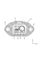
- FIG. 2 is a plan view showing a connector structure.
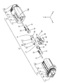
- FIG. 3 is an exploded perspective view showing the connector structure.
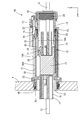
- FIG. 4 is a sectional view taken along line IV-IV in FIG.
- FIG. 5 is a sectional view taken along line VV in FIG.
- FIG. 6 is a partially enlarged perspective view showing a configuration in which the fuse is housed in the holder.
- FIG. 7 is a sectional view taken along line VII-VII in FIG.
- FIG. 8 is an exploded perspective view showing the connector structure according to the second embodiment.
- FIG. 9 is a partially enlarged perspective view showing a configuration in which the fuse is housed in the holder.
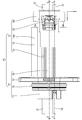
- FIG. 10 is a cross-sectional view showing a connector structure.
- the present disclosure is a connector with a built-in fuse, which is a housing, a fuse terminal attached to the housing, a holder attached to the housing, and a holder attached to the holder and electrically connected to the fuse terminal.
- the housing has a lock portion
- the holder has a lock receiving portion that elastically engages with the lock portion
- the holder accommodates the fuse detachably.
- the fuse has a terminal portion
- the fuse terminal has an elastic contact portion for a fuse that elastically contacts the terminal portion of the fuse.
- the terminal portion is provided on the outer surface of the fuse, and the elastic contact portion for the fuse of the fuse terminal is elastically fitted to the terminal portion.
- the efficiency of fuse replacement work is improved because the fuse can be electrically connected by elastically contacting the fuse terminal.
- the terminal portion of the fuse has a plate-shaped tab portion, the fuse terminal has a fuse cylinder portion into which the tab portion is inserted, and the fuse cylinder portion is the fuse. It is preferable to have an elastic contact portion for a fuse that protrudes into the cylinder portion and elastically contacts the tab portion inserted into the fuse cylinder portion.
- the efficiency of fuse replacement work is improved because the fuse can be electrically connected by elastically contacting the fuse terminal.
- a relay terminal is attached to the housing, and the holder has a bus bar accommodating portion for accommodating a bus bar electrically connected to the relay terminal, and the relay terminal is It has a bus bar cylinder portion in which the bus bar is housed, and the bus bar cylinder portion protrudes into the bus bar cylinder portion and elastically contacts the bus bar inserted into the bus bar cylinder portion. It is preferable to have a part.
- the present disclosure is a connector structure, comprising the fuse built-in connector according to any one of (1) to (4) above, and a mating connector that fits with the fuse built-in connector.
- the mating connector has a mating terminal that is electrically connected to the terminal portion of the fuse, and the mating terminal has an elastic contact portion for the mating fuse that elastically contacts the terminal portion of the fuse. ..
- the housing of the connector with a built-in fuse has a window portion in which the holder assembled to the housing is exposed, and the fuse attached to the holder is exposed from the window portion. It is preferable that the mating connector has a hood portion that closes the window portion and covers the fuse in a state where the fuse built-in connector and the mating connector are fitted.
- the fuse can be seen from the window, it is easy to check whether the fuse replacement has been completed. This makes it possible to improve the efficiency of the fuse replacement work. Further, when the connector with a built-in fuse and the mating connector are fitted, the window portion is closed by the hood portion, so that it is possible to prevent foreign matter from entering the inside of the connector structure from the window portion.
- the connector structure 10 is used by being attached to a device 11 such as a battery pack of a vehicle (not shown) such as an electric vehicle.
- the connector structure 10 includes a fuse built-in connector 13 having a fuse 12 and a mating connector 14 fitted with the fuse built-in connector 13.
- the mating connector 14 is attached to the device 11.
- the direction indicated by the arrow Z is upward
- the direction indicated by the arrow Y is forward
- the direction indicated by the arrow X is left.
- some members may be designated with reference numerals, and for other members, the reference numerals may be omitted.
- the fuse built-in connector 13 includes a housing 15, a fuse terminal 16 attached to the housing 15, a holder 17 attached to the housing 15, and a fuse terminal 16 and electricity attached to the holder 17.
- a fuse 12 is provided.
- Two electric wires 31 are led out rearward from the rear end of the fuse built-in connector 13 (see FIG. 2).
- the housing 15 is injection-molded with an insulating synthetic resin. As shown in FIG. 4, the housing 15 has a cylindrical shape that opens forward and backward.
- the housing 15 has an inner cylinder portion 18 located inside in the radial direction of the housing 15 and an outer cylinder portion 19 located outside.
- the inner cylinder portion 18 and the outer cylinder portion 19 are connected by a connecting portion 20 extending in the radial direction of the housing 15.
- a window portion 21 cut out rearward from the front end portion is formed on the upper wall 19A of the outer cylinder portion 19.
- the inside of the housing 15 is exposed from the window portion 21.
- the upper wall 18A of the inner cylinder portion 18 is provided with an arm base portion 22 projecting upward at a position closer to the rear end portion, and a lock is provided at the upper end of the arm base portion 22.
- the arm 23 is formed so as to extend forward and backward.
- the lock arm 23 is formed so as to be swingable in the vertical direction with the arm base 22 as a fulcrum.
- a locking hole 25 for locking the lock protrusion 24 of the mating connector 14, which will be described later, is penetrated in the portion near the front end of the lock arm 23 in the vertical direction.
- a through hole 28 is formed behind the lock portion 27 so as to vertically penetrate the upper wall 18A of the inner cylinder portion 18.
- Waterproof rubber stopper 29 As shown in FIG. 5, a rubber waterproof rubber stopper 29 is internally fitted in the rear end portion of the inner cylinder portion 18. The outer surface of the waterproof rubber stopper 29 and the inner surface of the rear end portion of the inner cylinder portion 18 are in close contact with each other, so that the housing 15 and the waterproof rubber stopper 29 are hermetically sealed. A rubber stopper holder 56 is externally fitted to the rear end portion of the inner cylinder portion 18. As a result, the waterproof rubber stopper 29 is held backward with respect to the inner cylinder portion 18 in a state of being prevented from coming off.
- the waterproof rubber stopper 29 has an electric wire insertion hole 30 penetrating in the front-rear direction.
- the waterproof rubber stopper 29 has two electric wire insertion holes 30 arranged in the left-right direction. With the electric wire 31 penetrating through each of the electric wire insertion holes 30, the outer surface of the electric wire 31 and the inner surface of the electric wire insertion hole 30 are in close contact with each other, so that the electric wire 31 and the waterproof rubber stopper 29 are hermetically sealed. ..
- a rubber sealing member 32 is externally fitted to the rear end portion of the inner cylinder portion 18.
- the seal member 32 has a substantially ring shape.
- the seal member 32 is attached to the front of the connecting portion 20 that connects the inner cylinder portion 18 and the outer cylinder portion 19.
- a fuse terminal 16 is connected to the front end of the electric wire 31 arranged on the left side of the two electric wires 31, and a bus bar is connected to the front end of the electric wire 31 arranged on the right side.
- the terminal 33 is connected.
- the fuse terminal 16 has an electric wire connection portion 34 crimped to the front end portion of the electric wire 31, and an elastic contact portion 35 for a fuse that extends forward from the electric wire connection portion 34 and is electrically connected to the fuse 12.
- the fuse terminal 16 is formed by pressing a metal plate material into a predetermined shape.
- the fuse terminal 16 is attached to the inner cylinder portion 18 by a known method such as a lance. By crimping the electric wire connecting portion 34 to the outer periphery of the electric wire 31, the electric wire 31 and the fuse terminal 16 are electrically connected.
- the fuse 12 has a cylindrical shape extending in the front-rear direction as a whole.
- Conductive terminal portions 36 are provided in a ring shape at the front end portion and the rear end portion of the fuse 12, respectively.
- the elastic contact portion 35 for a fuse has a metal plate material formed in a ring shape.
- the elastic contact portion 35 for the fuse is formed so that the diameter can be expanded.
- the inner diameter of the elastic contact portion 35 for a fuse is set to be smaller than the outer diameter of the terminal portion 36 of the fuse 12, which will be described later, in the natural state.
- bus bar terminal 33 As shown in FIG. 6, the bus bar terminal 33 has a wire connection portion 37 crimped to the front end portion of the wire 31 and a bus bar cylinder portion extending forward from the wire connection portion 37 and accommodating the bus bar 38 described later. 39 and.
- the bus bar terminal 33 is formed by pressing a metal plate material into a predetermined shape.
- the bus bar terminal 33 is attached to the inner cylinder portion 18 by a known method such as a lance. By crimping the electric wire connecting portion 37 to the outer periphery of the electric wire 31, the electric wire 31 and the bus bar terminal 33 are electrically connected.
- the bus bar 38 is formed by pressing a metal plate material into a predetermined shape.
- the bus bar 38 has a main body portion 40 having a rectangular shape when viewed from above, and tabs 41 projecting forward and backward from the front end and the rear end of the main body portion 40, respectively.
- the width dimension of the tab 41 in the left-right direction is set smaller than the width dimension of the main body 40 in the left-right direction.
- the bus bar cylinder 39 is formed in a square cylinder extending in the front-rear direction. Inside the bus bar cylinder 39, an elastic contact portion 42 for the bus bar, which is elastically deformable, is formed so as to project inward of the bus bar cylinder 39.
- the elastic contact portion 42 for the bus bar elastically contacts the tab 41.
- the bus bar 38 and the bus bar terminal 33 are electrically connected (see FIG. 7).
- a holder 17 formed by injection molding an insulating synthetic resin is attached to the inside of the housing 15.
- a lock receiving portion 26 extending rearward is formed at the rear end portion of the holder 17.
- the lock receiving portion 26 is formed in a plate shape extending in the front-rear direction.
- On the upper surface of the lock receiving portion 26, a convex portion 43 protruding upward is formed at a position closer to the rear end portion.
- the holder 17 is generally formed in a box shape that opens upward.
- the holder 17 is formed with a partition wall 44 extending in the front-rear direction near the center position in the left-right direction.
- a fuse accommodating portion 45 in which the fuse 12 is accommodated is formed on the left side of the holder 17, and a bus bar accommodating portion 46 in which the bus bar 38 is accommodated is formed on the right side of the holder 17.
- the length dimension in the front-rear direction of the fuse accommodating portion 45 is set to be the same as or slightly smaller than the length dimension in the front-rear direction of the region sandwiched between the two terminal portions 36 of the fuse 12.
- the length dimension of the bus bar accommodating portion 46 in the front-rear direction is set to be the same as or slightly smaller than the length dimension of the main body portion 40 of the bus bar 38 in the front-rear direction.
- the fuse 12 held in the holder 17 is exposed from the window portion 21 formed in the outer cylinder portion 19. As a result, the fuse 12 can be visually recognized from above through the window portion 21.
- the mating connector 14 is adapted to be attached to the device 11.
- the device 11 has a mounting hole 49 penetrated in the front-rear direction.
- the mating connector 14 is inserted into the mounting hole 49 from the rear.
- the mating connector 14 is injection-molded with an insulating synthetic resin.
- the mating connector 14 has a tubular hood portion 50 that opens forward and backward, a tower portion 51 provided inward in the radial direction of the hood portion 50, and a hood portion from a position closer to the front end portion of the hood portion 50. It has a flange 52 extending outward in the radial direction of 50.
- the hood portion 50 and the tower portion 51 are connected by a connecting portion 53 extending in the radial direction of the hood portion 50.
- a lock protrusion 24 projecting upward is formed on the upper surface 50A of the hood portion 50 at a position closer to the front end portion.
- metal collars 54 are embedded in the left and right ends of the flange 52, respectively.
- the collar 54 has a cylindrical shape extending in the front-rear direction.
- a bolt (not shown) is inserted through the collar 54, and the bolt is screwed into the device 11 so that the mating connector 14 is fixed to the device 11.
- a rubber seal ring 55 is externally fitted to the front end portion of the hood portion 50.
- the front end portion of the hood portion 50 is inserted into the mounting hole 49 described above.
- the outer surface of the seal ring 55 is in close contact with the inner surface of the attachment hole 49. As a result, the mating connector 14 and the device 11 are hermetically sealed.
- the hood portion 50 of the mating connector 14 is inserted from the front into the space between the outer cylinder portion 19 and the inner cylinder portion 18 of the fuse built-in connector 13. With the hood portion 50 inserted between the outer cylinder portion 19 and the inner cylinder portion 18, the inner surface of the hood portion 50 and the outer surface of the seal member 32 outerly fitted to the inner cylinder portion 18 are brought into close contact with each other. It has become. As a result, the mating connector 14 and the fuse built-in connector 13 are hermetically sealed.
- the window portion 21 formed in the outer cylinder portion 19 is closed from below by the hood portion 50. It has become. Further, the hood portion 50 covers the fuse 12 from above the holder 17.
- the tower portion 51 accommodates a fuse terminal 16 electrically connected to the fuse 12 and a bus bar terminal 33 electrically connected to the bus bar 38.
- the fuse terminal 16 and the bus bar terminal 33 are held in the tower portion 51 by a known method such as a lance.
- the fuse terminal 16 is housed on the left side of the tower portion 51, and the bus bar terminal 33 is housed on the right side.
- the fuse terminal 16 and the bus bar terminal 33 are each connected to the rear end of the electric wire 31. Two electric wires 31 are led out forward from the front end portion of the tower portion 51.
- the fuse terminal 16 and the bus bar terminal 33 housed in the tower portion 51 have the same configuration as the fuse terminal 16 and the bus bar terminal 33 housed in the fuse built-in connector 13, they are designated by the same reference numerals. The explanation is omitted.
- the waterproof rubber stopper 29 is internally fitted into the inner cylinder portion 18 formed in the housing 15 of the fuse built-in connector 13 from the rear. Further, the seal member 32 is fitted from the front to the inner cylinder portion 18 of the housing 15.
- the fuse terminal 16 and the bus bar terminal 33 are inserted from the rear into the electric wire insertion hole 30 of the waterproof rubber stopper 29 and attached to the inner cylinder portion 18 of the housing 15.
- the rubber stopper holder 56 is externally fitted to the rear end portion of the inner cylinder portion 18 of the housing 15.
- the fuse 12 is accommodated in the fuse accommodating portion 45 of the holder 17 from above. Further, the bus bar 38 is accommodated in the bus bar accommodating portion 46 of the holder 17 from above.
- the fuse elastic contact portion 35 of the fuse terminal 16 is fitted onto the terminal portion 36 of the fuse 12.
- the elastic contact portion 35 for a fuse comes into contact with the terminal portion 36 of the fuse 12 by elastic force by expanding and deforming the elastic contact portion 35 for a fuse in the radial direction.
- the fuse 12 and the fuse terminal 16 are electrically connected.
- the tab 41 of the bus bar 38 is inserted into the bus bar cylinder portion 39 of the bus bar terminal 33.
- the elastic contact portion 42 for the bus bar elastically contacts the tab 41.
- the bus bar 38 and the bus bar terminal 33 are electrically connected. This completes the fuse built-in connector 13.
- the fuse terminal 16 Connect the fuse terminal 16 to the rear end of one electric wire 31, and connect the bus bar terminal 33 to the rear end of the other electric wire 31.
- the fuse terminal 16 and the bus bar terminal 33 are attached to the tower portion 51 of the mating connector 14.
- the seal ring 55 is externally fitted at a position near the front end of the hood portion 50.
- the hood portion 50 of the mating connector 14 is inserted between the inner cylinder portion 18 and the outer cylinder portion 19 of the fuse built-in connector 13, so that the fuse built-in connector 13 is attached to the mating connector 14 fixed to the device 11. Bring it closer from behind.
- the lock protrusion 24 formed on the upper surface 50A of the hood portion 50 comes into contact with the front end portion of the lock arm 23 from the front. Then, the lock arm 23 swings so that the front end portion of the lock arm 23 moves upward and the rear end portion of the lock arm 23 moves downward with the arm base 22 as a fulcrum.
- the lock arm 23 is restored and deformed, and the lock protrusion 24 of the other party connector 14 enters the inside of the locking hole 25 of the lock arm 23.
- the lock protrusion 24 comes into contact with the mouth edge portion of the locking hole 25 from the rear, the mating connector 14 and the fuse built-in connector 13 are held in a front-rear direction in a retaining state. This completes the connector structure 10.
- the lock arm 23 By pushing down the rear end of the lock arm 23, the lock arm 23 is swung with the arm base 22 as a fulcrum. As a result, the front end portion of the lock arm 23 moves upward. As a result, the engagement between the lock protrusion 24 and the rim portion of the locking hole 25 is released. In this state, the connector 13 with a built-in fuse is pulled out backward.
- the convex portion 43 exposed from the through hole 28 of the inner cylinder portion 18 is pushed downward using a jig (not shown). Then, the engagement between the lock portion 27 and the lock receiving portion 26 is released. In this state, the holder 17 is detached from the housing 15.
- the connector 13 with a built-in fuse is fitted with the mating connector 14.
- the fuse built-in connector 13 is electrically attached to the housing 15, the fuse terminal 16 attached to the housing 15, the holder 17 attached to the housing 15, the holder 17, and the fuse terminal 16.
- the housing 15 has a lock portion 27, the holder 17 has a lock receiving portion 26 that elastically engages with the lock portion 27, and the holder 17 has a fuse 12 that can be attached and detached.
- the fuse 12 has a terminal portion 36, and the fuse terminal 16 has an elastic contact portion 35 for a fuse that elastically contacts the terminal portion 36 of the fuse 12.
- the engagement between the lock portion 27 and the lock receiving portion 26 is released to separate the housing 15 and the holder 17.
- the elastic contact portion 35 for the fuse of the fuse terminal 16 is separated from the terminal portion 36 of the fuse 12, so that the electrical connection between the fuse terminal 16 and the fuse 12 is cut off.
- the fuse 12 is taken out from the fuse accommodating portion 45 of the holder 17 and replaced with a new fuse 12.
- a holder 17 having a new fuse 12 attached to the fuse accommodating portion 45 is attached to the housing 15.
- the fuse terminal 16 and the terminal portion 36 of the fuse 12 are electrically connected via the elastic contact portion 35 for the fuse.
- the work of removing the screw portion and the nut and the work of screwing the screw portion and the nut after replacing the fuse 12 become unnecessary, so that the efficiency of the replacement work of the fuse 12 can be improved.
- the terminal portion 36 is provided on the outer surface of the fuse 12, and the elastic contact portion 35 for the fuse of the fuse terminal 16 is elastically fitted to the terminal portion 36. ..
- the fuse 12 and the fuse terminal 16 can be electrically connected by elastically contacting each other, the efficiency of the fuse 12 replacement work is improved.
- the bus bar terminal 33 is attached to the housing 15, and the holder 17 has a bus bar accommodating portion 46 in which the bus bar 38 electrically connected to the bus bar terminal 33 is accommodated.
- the bus bar terminal 33 has a bus bar cylinder portion 39 in which the bus bar 38 is housed, and the bus bar cylinder portion 39 projects into the bus bar cylinder portion 39 and is inserted into the bus bar cylinder portion 39. It has an elastic contact portion 42 for a bus bar that is in elastic contact with the bus bar.
- a circuit in which the fuse 12 is connected in series and a circuit in which the bus bar 38 is connected in series can be configured by one connector 13 with a built-in fuse.
- the connector 13 having a built-in fuse and the mating connector 14 mating with the connector 13 having a built-in fuse are provided, and the mating connector 14 is a fuse terminal electrically connected to the terminal portion 36 of the fuse 12.
- the fuse terminal 16 has a fuse elastic contact portion 35 that elastically contacts the terminal portion 36 of the fuse 12.
- the housing 15 of the connector 13 with a built-in fuse has a window portion 21 in which the holder 17 assembled to the housing 15 is exposed, and the fuse 12 attached to the holder 17 is provided from the window portion 21.
- the mating connector 14 is exposed and has a hood portion 50 that closes the window portion 21 and covers the fuse 12 in a state where the fuse built-in connector 13 and the mating connector 14 are fitted.
- the fuse 12 When the fuse built-in connector 13 and the mating connector 14 are separated, the fuse 12 can be visually recognized from the window portion 21, so it can be easily confirmed whether or not the fuse 12 replacement is completed. Thereby, the efficiency of the replacement work of the fuse 12 can be improved. Further, when the connector 13 with a built-in fuse and the mating connector 14 are fitted together, the window portion 21 is closed by the hood portion 50, so that it is possible to prevent foreign matter from entering the inside of the connector structure 10 from the window portion 21.
- the terminal portion 73 of the fuse 72 attached to the connector with built-in fuse has a ring shape attached to the outer surface of the fuse 72. It includes an outer fitting portion 74 to be formed, and a plate-shaped tab portion 75 extending downward from the lower end of the outer fitting portion 74 and extending in a direction away from the fuse 72 toward the front or the rear. The tip portion of the tab portion 75 projects outward from the outer fitting portion 74 of the fuse 72 and extends in the front-rear direction.
- a fuse accommodating portion 77 in which the fuse 72 is accommodated is provided on the left side of the holder 76, and a bus bar accommodating portion 79 in which the bus bar 78 is accommodated is provided on the right side of the holder 76.
- the length dimension of the fuse accommodating portion 77 in the front-rear direction is set to be longer than the length dimension of the bus bar accommodating portion 79 in the front-rear direction.
- the width dimension of the tab portion 75 provided in the terminal portion 73 of the fuse 72 in the left-right direction is set to be substantially the same as the width dimension in the left-right direction of the tab 80 provided in the bus bar 78.
- the vertical thickness dimension of the tab portion 75 provided in the terminal portion 73 of the fuse 72 is set to be substantially the same as the vertical thickness dimension of the tab 80 provided in the bus bar 78.
- the terminal 81 (an example of the fuse terminal) connected to the tab portion 75 provided in the terminal portion 73 of the fuse 72 is connected to the bus bar 78. It has the same shape as the terminal 81 (an example of a terminal for a bus bar). Therefore, the terminal 81 connected to the fuse 72 and the terminal 81 connected to the bus bar 78 are designated by the same reference numerals, and duplicate description will be omitted.
- the terminal 81 has a wire connection portion 82 crimped to the end of the wire 31 and a cylinder portion 83 extending from the wire connection portion 82 (an example of a fuse cylinder portion and an example of a bus bar cylinder portion). ) And. Inside the tubular portion 83, the tab portion 75 of the fuse 72 or the tab 80 of the bus bar 78 is inserted. Inside the tubular portion 83, an elastic contact portion 84 that can be elastically deformed (an example of an elastic contact portion for a fuse and an example of an elastic contact portion for a bus bar) is arranged. The elastic contact portion 84 is adapted to elastically contact the tab portion 75 or the tab 80.
- the terminal 81 is housed in the housing 85 of the connector 71 with a built-in fuse.
- a lance 86 extending forward is provided in the housing 85, and the tubular portion 83 of the terminal 81 comes into contact with the front end portion of the lance 86 from the front so that the terminal 81 is held in a rearward retaining state. It has become.
- the terminal 81 is housed in the tower portion 87 of the mating connector 89.
- a lance 88 extending rearward is provided in the tower portion 87, and when the tubular portion 83 of the terminal 81 comes into contact with the rear end portion of the lance 88 from the rear, the terminal 81 is held forward in a retaining state. It has become like.
- the terminal portion 73 of the fuse 72 has a tab portion 75 having a plate shape
- the terminal 81 has a tubular portion 83 into which the tab portion 75 is inserted
- the tubular portion 83 has a tubular portion. It has an elastic contact portion 84 that protrudes into the 83 and elastically contacts the tab portion 75 inserted into the tubular portion 83.
- the fuse 72 and the terminal 81 can be electrically connected by elastically contacting each other, the efficiency of the fuse 72 replacement work is improved.
- the number of electric wires 31 connected to the fuse built-in connector 13 may be one, or may be three or more.
- the connector 13 with a built-in fuse is not limited to the electric wire 31, and any conductive member such as a bus bar 38 can be connected.
- the number of electric wires 31 connected to the mating connector 14 may be one, or may be three or more. It is not limited to the electric wire 31 that is connected to the mating connector 14, but any conductive member such as a bus bar 38 can be connected.
- the housing 15 may have no window portion 21 and may cover the outer periphery of the holder 17 so that the holder 17 is not exposed to the outside.
Landscapes
- Details Of Connecting Devices For Male And Female Coupling (AREA)
- Fuses (AREA)
Abstract
ハウジング15と、前記ハウジング15に取り付けられるヒューズ用端子16と、前記ハウジング15に取り付けられるホルダ17と、前記ホルダ17に取り付けられるとともに、前記ヒューズ用端子16と電気的に接続されるヒューズ12と、を備え、前記ハウジング15はロック部27を有し、前記ホルダ17は前記ロック部27と弾性的に係止するロック受け部26を有し、前記ホルダ17は、前記ヒューズ12が着脱可能に収容されるヒューズ収容部45を有し、前記ヒューズ12は端子部36を有し、前記ヒューズ用端子16は、前記ヒューズ12の前記端子部36と弾性的に接触するヒューズ用弾性接触部35を有するヒューズ内蔵コネクタ13。
Description
本開示は、ヒューズ内蔵コネクタ、およびコネクタ構造体に関する。
従来、ヒューズ内蔵コネクタとして特開2015-79723号公報に記載のものが知られている。このヒューズ内蔵コネクタにおいては、ヒューズは、バスバー片にネジ部およびナットによって固定されている。ヒューズは、ネジ部またはナットを緩めて外した後に、交換される。交換された新しいヒューズは、再び、ネジ部およびナットによって固定される。
しかしながら上記の構成によれば、ヒューズ交換の際に、ネジ部またはナットが脱落するおそれがあるため、ヒューズ交換作業の効率が低下するという問題があった。
本開示は上記のような事情に基づいて完成されたものであって、ヒューズの交換作業の効率が向上されたヒューズ内蔵コネクタにかかる技術を提供することを目的とする。
本開示は、ヒューズ内蔵コネクタであって、ハウジングと、前記ハウジングに取り付けられるヒューズ用端子と、前記ハウジングに取り付けられるホルダと、前記ホルダに取り付けられるとともに、前記ヒューズ用端子と電気的に接続されるヒューズと、を備え、前記ハウジングはロック部を有し、前記ホルダは前記ロック部と弾性的に係止するロック受け部を有し、前記ホルダは、前記ヒューズが着脱可能に収容されるヒューズ収容部を有し、前記ヒューズは端子部を有し、前記ヒューズ用端子は、前記ヒューズの前記端子部と弾性的に接触するヒューズ用弾性接触部を有する。
本開示によれば、ヒューズの交換作業の効率を向上させることができる。
[本開示の実施形態の説明]
最初に本開示の実施態様を列挙して説明する。
最初に本開示の実施態様を列挙して説明する。
(1)本開示は、ヒューズ内蔵コネクタであって、ハウジングと、前記ハウジングに取り付けられるヒューズ用端子と、前記ハウジングに取り付けられるホルダと、前記ホルダに取り付けられるとともに、前記ヒューズ用端子と電気的に接続されるヒューズと、を備え、前記ハウジングはロック部を有し、前記ホルダは前記ロック部と弾性的に係止するロック受け部を有し、前記ホルダは、前記ヒューズが着脱可能に収容されるヒューズ収容部を有し、前記ヒューズは端子部を有し、前記ヒューズ用端子は、前記ヒューズの前記端子部と弾性的に接触するヒューズ用弾性接触部を有する。
ロック部とロック受け部との係合を解除してハウジングとホルダとを分離させる。すると、ヒューズ用端子のヒューズ用弾性接触部がヒューズの端子部と離れることにより、ヒューズ用端子とヒューズとの電気的な接続が切断される。ホルダのヒューズ収容部からヒューズを取り出し、新しいヒューズと交換する。ヒューズ収容部に新しいヒューズが取り付けられたホルダをハウジングに取り付ける。すると、ヒューズ用端子と、ヒューズの端子部とが、ヒューズ用弾性接触部を介して電気的に接続される。このように、ネジ部およびナットを外す作業と、ヒューズ交換後にネジ部およびナットを螺合させる作業が不要となるので、ヒューズの交換作業の効率を向上させることができる。
(2)前記ヒューズの外面には前記端子部が設けられており、前記ヒューズ用端子の前記ヒューズ用弾性接触部は、前記端子部に弾性的に外嵌するようになっていることが好ましい。
ヒューズとヒューズ用端子とを弾性的に接触させることにより電気的に接続できるのでヒューズの交換作業の効率が向上する。
(3)前記ヒューズの前記端子部は、板状をなすタブ部を有し、前記ヒューズ用端子は前記タブ部が挿入されるヒューズ用筒部を有し、前記ヒューズ用筒部は、前記ヒューズ用筒部内に突出して前記ヒューズ用筒部内に挿入された前記タブ部と弾性的に接触するヒューズ用弾性接触部を有することが好ましい。
ヒューズとヒューズ用端子とを弾性的に接触させることにより電気的に接続できるのでヒューズの交換作業の効率が向上する。
(4)前記ハウジングには中継用端子が取り付けられており、前記ホルダは、前記中継用端子と電気的に接続されるバスバーが収容されるバスバー収容部を有しており、前記中継用端子は前記バスバーが収容されるバスバー用筒部を有し、前記バスバー用筒部は、前記バスバー用筒部内に突出して前記バスバー用筒部内に挿入された前記バスバーと弾性的に接触するバスバー用弾性接触部を有することが好ましい。
1つのヒューズ内蔵コネクタによって、ヒューズが直列接続された回路と、バスバーが直列接続された回路とを構成することができる。
(5)本開示は、コネクタ構造体であって、上記の(1)から(4)のいずれか一つに記載のヒューズ内蔵コネクタと、前記ヒューズ内蔵コネクタと嵌合する相手方コネクタと、を備え、前記相手方コネクタは、前記ヒューズの前記端子部と電気的に接続される相手方端子を有し、前記相手方端子は、前記ヒューズの前記端子部と弾性的に接触する相手方ヒューズ用弾性接触部を有する。
相手方コネクタとヒューズ内蔵コネクタとの嵌合を解除すると、相手方端子の相手方ヒューズ用弾性接触部と、ヒューズの端子部との電気的な接続が切断される。このように、相手方端子とヒューズの端子部との電気的な接続に際して、ネジ部およびナットが不要となるので、ヒューズ交換の作業性を向上させることができる。
(6)前記ヒューズ内蔵コネクタの前記ハウジングは、前記ハウジングに組み付けられた状態の前記ホルダが露出する窓部を有し、前記窓部からは前記ホルダに取り付けられた前記ヒューズが露出しており、前記相手方コネクタは、前記ヒューズ内蔵コネクタと前記相手方コネクタとが嵌合した状態で前記窓部を塞いで前記ヒューズを覆うフード部を有することが好ましい。
窓部からヒューズを視認できるので、ヒューズ交換が完了したか否かを容易に確認できる。これにより、ヒューズ交換作業の効率を向上させることができる。また、ヒューズ内蔵コネクタと相手方コネクタとを嵌合させると、フード部によって窓部が塞がれるので、コネクタ構造体の内部に窓部から異物が侵入することを抑制できる。
[本開示の実施形態の詳細]
以下に、本開示の実施形態について説明する。本開示はこれらの例示に限定されるものではなく、特許請求の範囲によって示され、特許請求の範囲と均等の意味および範囲内での全ての変更が含まれることが意図される。
以下に、本開示の実施形態について説明する。本開示はこれらの例示に限定されるものではなく、特許請求の範囲によって示され、特許請求の範囲と均等の意味および範囲内での全ての変更が含まれることが意図される。
<実施形態1>
本開示の実施形態1について、図1から図7を参照しつつ説明する。本実施形態にかかるコネクタ構造体10は、電気自動車等の車両(図示せず)の電池パック等の機器11に取り付けて使用される。図1および図2に示されるように、コネクタ構造体10は、ヒューズ12を備えたヒューズ内蔵コネクタ13と、このヒューズ内蔵コネクタ13と嵌合する相手方コネクタ14とを備える。相手方コネクタ14は機器11に取り付けられている。以下の記載においては、説明の便宜上、矢線Zで示される方向を上方とし、矢線Yで示される方向を前方とし、矢線Xで示される方向を左方とする。なお、複数の同一部材については一部の部材に符号を付し、他の部材については符号を省略する場合がある。
本開示の実施形態1について、図1から図7を参照しつつ説明する。本実施形態にかかるコネクタ構造体10は、電気自動車等の車両(図示せず)の電池パック等の機器11に取り付けて使用される。図1および図2に示されるように、コネクタ構造体10は、ヒューズ12を備えたヒューズ内蔵コネクタ13と、このヒューズ内蔵コネクタ13と嵌合する相手方コネクタ14とを備える。相手方コネクタ14は機器11に取り付けられている。以下の記載においては、説明の便宜上、矢線Zで示される方向を上方とし、矢線Yで示される方向を前方とし、矢線Xで示される方向を左方とする。なお、複数の同一部材については一部の部材に符号を付し、他の部材については符号を省略する場合がある。
[ヒューズ内蔵コネクタ13]
図3に示されるように、ヒューズ内蔵コネクタ13は、ハウジング15と、ハウジング15に取り付けられるヒューズ用端子16と、ハウジング15に取り付けられるホルダ17と、ホルダ17に取り付けられるとともにヒューズ用端子16と電気的に接続されるヒューズ12と、を備える。ヒューズ内蔵コネクタ13の後端部からは、2本の電線31が後方に導出されている(図2参照)。
図3に示されるように、ヒューズ内蔵コネクタ13は、ハウジング15と、ハウジング15に取り付けられるヒューズ用端子16と、ハウジング15に取り付けられるホルダ17と、ホルダ17に取り付けられるとともにヒューズ用端子16と電気的に接続されるヒューズ12と、を備える。ヒューズ内蔵コネクタ13の後端部からは、2本の電線31が後方に導出されている(図2参照)。
[ハウジング15]
ハウジング15は、絶縁性の合成樹脂が射出成型されてなる。図4に示されるように、ハウジング15は、前方および後方に開口した筒状をなしている。ハウジング15は、ハウジング15の径方向について内側に位置する内筒部18と、外側に位置する外筒部19と、を有する。内筒部18と外筒部19とは、ハウジング15の径方向に延びる連結部20によって連結されている。
ハウジング15は、絶縁性の合成樹脂が射出成型されてなる。図4に示されるように、ハウジング15は、前方および後方に開口した筒状をなしている。ハウジング15は、ハウジング15の径方向について内側に位置する内筒部18と、外側に位置する外筒部19と、を有する。内筒部18と外筒部19とは、ハウジング15の径方向に延びる連結部20によって連結されている。
図3に示されるように、外筒部19の上壁19Aには、前端部から後方に切り欠かれた窓部21が形成されている。窓部21からは、ハウジング15の内部が露出するようになっている。
図4に示されるように、内筒部18の上壁18Aには、後端部寄りの位置に、上方に突出するアーム基部22が設けられており、このアーム基部22の上端には、ロックアーム23が前方および後方に延びて形成されている。ロックアーム23は、アーム基部22を支点として上下方向に揺動可能に形成されている。ロックアーム23の前端部寄りの部分には後述する相手方コネクタ14のロック突起24が係止する係止孔25が上下方向に貫通されている。
図4に示されるように、内筒部18の上壁18Aには、前端部寄りの位置に、後述するホルダ17のロック受け部26が弾性的に係合するロック部27が、内筒部18の内方に突出して形成されている。ロック部27の後方には、内筒部18の上壁18Aを上下に貫通する貫通孔28が形成されている。
[防水ゴム栓29]
図5に示されるように、内筒部18の後端部には、ゴム製の防水ゴム栓29が内嵌されている。防水ゴム栓29の外面と、内筒部18の後端部の内面とが密着することにより、ハウジング15と防水ゴム栓29とが液密にシールされるようになっている。内筒部18の後端部にはゴム栓ホルダ56が外嵌されている。これにより、防水ゴム栓29が内筒部18に対して後方へ抜け止め状態で保持されるようになっている。
図5に示されるように、内筒部18の後端部には、ゴム製の防水ゴム栓29が内嵌されている。防水ゴム栓29の外面と、内筒部18の後端部の内面とが密着することにより、ハウジング15と防水ゴム栓29とが液密にシールされるようになっている。内筒部18の後端部にはゴム栓ホルダ56が外嵌されている。これにより、防水ゴム栓29が内筒部18に対して後方へ抜け止め状態で保持されるようになっている。
図5に示されるように、防水ゴム栓29は前後方向に貫通する電線挿通孔30を有する。詳細には図示しないが、本実施形態では、防水ゴム栓29は、左右方向に並ぶ2つの電線挿通孔30を有する。電線挿通孔30のそれぞれに電線31が貫通された状態で、電線31の外面と、電線挿通孔30の内面とが密着することにより、電線31と防水ゴム栓29とが液密にシールされる。
[シール部材32]
図5に示されるように、内筒部18の後端部には、ゴム製のシール部材32が外嵌されている。シール部材32は概ねリング状をなしている。シール部材32は、内筒部18と外筒部19とを連結する連結部20の前方に取り付けられている。
図5に示されるように、内筒部18の後端部には、ゴム製のシール部材32が外嵌されている。シール部材32は概ねリング状をなしている。シール部材32は、内筒部18と外筒部19とを連結する連結部20の前方に取り付けられている。
[ヒューズ用端子16]
図6に示されるように、2つの電線31のうち左側に配された電線31の前端部にはヒューズ用端子16が接続されており、右側に配された電線31の前端部にはバスバー用端子33が接続されている。ヒューズ用端子16は、電線31の前端部に圧着された電線接続部34と、電線接続部34から前方に延びるとともにヒューズ12と電気的に接続されるヒューズ用弾性接触部35と、を有する。ヒューズ用端子16は金属板材を所定の形状にプレス加工されることにより形成される。
図6に示されるように、2つの電線31のうち左側に配された電線31の前端部にはヒューズ用端子16が接続されており、右側に配された電線31の前端部にはバスバー用端子33が接続されている。ヒューズ用端子16は、電線31の前端部に圧着された電線接続部34と、電線接続部34から前方に延びるとともにヒューズ12と電気的に接続されるヒューズ用弾性接触部35と、を有する。ヒューズ用端子16は金属板材を所定の形状にプレス加工されることにより形成される。
ヒューズ用端子16は、ランス等の公知の手法により、内筒部18内に取り付けられている。電線接続部34が電線31の外周に圧着されることにより、電線31とヒューズ用端子16とが電気的に接続される。
図3に示されるように、ヒューズ12は、全体として、前後方向に延びる円柱形状をなしている。ヒューズ12の前端部および後端部には、それぞれ、導電性の端子部36がリング状に設けられている。
図6に示されるように、ヒューズ用弾性接触部35は、金属板材がリング状に形成されてなる。ヒューズ用弾性接触部35は拡径可能に形成されている。ヒューズ用弾性接触部35の内径は、自然状態においては後述するヒューズ12の端子部36の外径よりも小さく設定されている。ヒューズ用弾性接触部35がヒューズ12の端子部36に外嵌した状態では、ヒューズ用弾性接触部35は弾性的に拡径変形するようになっており、ヒューズ用弾性接触部35の径方向の内方に弾発力を及ぼすようになっている。これにより、ヒューズ用弾性接触部35は、ヒューズ12の端子部36に対して弾性的に接触するようになっている。
[バスバー用端子33]
図6に示されるように、バスバー用端子33は、電線31の前端部に圧着された電線接続部37と、電線接続部37から前方に延びるとともに後述するバスバー38が収容されるバスバー用筒部39と、を有する。バスバー用端子33は金属板材を所定の形状にプレス加工されることにより形成される。
図6に示されるように、バスバー用端子33は、電線31の前端部に圧着された電線接続部37と、電線接続部37から前方に延びるとともに後述するバスバー38が収容されるバスバー用筒部39と、を有する。バスバー用端子33は金属板材を所定の形状にプレス加工されることにより形成される。
バスバー用端子33は、ランス等の公知の手法により、内筒部18内に取り付けられている。電線接続部37が電線31の外周に圧着されることにより、電線31とバスバー用端子33とが電気的に接続される。
バスバー38は、金属板材を所定形状にプレス加工して形成される。バスバー38は上方から見て長方形状をなす本体部40と、本体部40の前端および後端から、それぞれ、前方および後方に突出するタブ41を有する。タブ41の左右方向の幅寸法は、本体部40の左右方向の幅寸法よりも小さく設定されている。
バスバー用筒部39は、前後方向に延びる角筒状に形成されている。バスバー用筒部39の内部には、弾性変形可能なバスバー用弾性接触部42が、バスバー用筒部39の内方に突出して形成されている。バスバー38のタブ41がバスバー用筒部39内に前方から挿入されると、バスバー用弾性接触部42がタブ41と弾性的に接触する。これにより、バスバー38とバスバー用端子33とが電気的に接続されるようになっている(図7参照)。
[ホルダ17]
図6に示されるように、ハウジング15の内部には、絶縁性の合成樹脂が射出成型されてなるホルダ17が取り付けられている。ホルダ17の後端部には、後方に延びるロック受け部26が形成されている。ロック受け部26が前後方向に延びる板状に形成されている。ロック受け部26の上面には、後端部寄りの位置に、上方に突出する凸部43が形成されている。この凸部43が後方からロック部27に接触することにより、ホルダ17が、ハウジング15に対して前方に抜け止め状態で保持されるようになっている。ロック部27とロック受け部26とが係合した状態では、内筒部18に形成された貫通孔28から、凸部43が露出するようになっている。
図6に示されるように、ハウジング15の内部には、絶縁性の合成樹脂が射出成型されてなるホルダ17が取り付けられている。ホルダ17の後端部には、後方に延びるロック受け部26が形成されている。ロック受け部26が前後方向に延びる板状に形成されている。ロック受け部26の上面には、後端部寄りの位置に、上方に突出する凸部43が形成されている。この凸部43が後方からロック部27に接触することにより、ホルダ17が、ハウジング15に対して前方に抜け止め状態で保持されるようになっている。ロック部27とロック受け部26とが係合した状態では、内筒部18に形成された貫通孔28から、凸部43が露出するようになっている。
ホルダ17は、概ね、上方に開口する箱状に形成されている。ホルダ17には、左右方向の中央位置付近に、前後方向に延びる仕切り壁44が形成されている。この仕切り壁44により仕切られることにより、ホルダ17の左側にはヒューズ12が収容されるヒューズ収容部45が形成され、ホルダ17の右側にはバスバー38が収容されるバスバー収容部46が形成されている。
ヒューズ収容部45の前後方向の長さ寸法は、ヒューズ12のうち2つの端子部36の間に挟まれた領域の前後方向の長さ寸法と、同じか、やや小さく設定されている。これにより、ヒューズ収容部45にヒューズ12を上方から組み付けると、ヒューズ収容部45の前端および後端から、ヒューズ12の端子部36が、前方および後方にそれぞれ突出するようになっている。ヒューズ収容部45には、ヒューズ12のうち2つの端子部36に挟まれた領域に上方から係止して、ヒューズ12を上方に抜け止め保持するヒューズ係止部47が設けられている。
バスバー収容部46の前後方向の長さ寸法は、バスバー38の本体部40の前後方向の長さ寸法と、同じか、やや小さく設定されている。これにより、バスバー収容部46にバスバー38を上方から組み付けると、バスバー収容部46の前端および後端から、バスバー38のタブ41が、前方および後方にそれぞれ突出するようになっている。バスバー収容部46には、バスバー38の本体部40に上方から係止して、バスバー38を上方に抜け止め保持するバスバー係止部48が設けられている。
ホルダ17がハウジング15に取り付けられた状態においては、外筒部19に形成された窓部21から、ホルダ17に保持されたヒューズ12が露出している。これにより、窓部21を通して、ヒューズ12を上方から視認できるようになっている。
[相手方コネクタ14]
図4に示されるように、相手方コネクタ14は、機器11に取り付けられるようになっている。機器11は、前後方向に貫通された取り付け孔49を有する。この取り付け孔49に相手方コネクタ14が後方から挿入されるようになっている。
図4に示されるように、相手方コネクタ14は、機器11に取り付けられるようになっている。機器11は、前後方向に貫通された取り付け孔49を有する。この取り付け孔49に相手方コネクタ14が後方から挿入されるようになっている。
図4に示されるように、相手方コネクタ14は、絶縁性の合成樹脂が射出成型されてなる。相手方コネクタ14は、前方および後方に開口する筒状をなすフード部50と、フード部50の径方向の内方に設けられたタワー部51と、フード部50の前端部寄りの位置からフード部50の径方向の外方に延びるフランジ52と、を有する。フード部50と、タワー部51とはフード部50の径方向に延びる連結部53によって連結されている。
図4に示されるように、フード部50の上面50Aには、前端部寄りの位置に、上方に突出するロック突起24が形成されている。このロック突起24がロックアーム23の係止孔25の孔縁部に後方から接触することにより、相手方コネクタ14とヒューズ内蔵コネクタ13とが、抜け止め状態で保持されるようになっている。
図7に示されるように、フランジ52部の左右両端部には、それぞれ、金属製のカラー54が埋設されている。カラー54は前後方向に延びる円筒形状をなしている。カラー54にはボルト(図示せず)が挿通されて、このボルトが機器11に螺合されることにより、相手方コネクタ14が機器11に固定されるようになっている。
図4に示されるように、フード部50の前端部には、ゴム製のシールリング55が外嵌されている。フード部50の前端部は上記した取り付け孔49に挿入されるようになっている。相手方コネクタ14が機器11に取り付けられた状態で、シールリング55の外面は、取り付け孔49の内面と密着するようになっている。これにより、相手方コネクタ14と、機器11とが液密にシールされるようになっている。
図5に示されるように、相手方コネクタ14のフード部50は、ヒューズ内蔵コネクタ13の外筒部19と内筒部18との間の空間に、前方から挿入されるようになっている。フード部50が、外筒部19と内筒部18の間に挿入された状態で、フード部50の内面と、内筒部18に外嵌されたシール部材32の外面とが密着するようになっている。これにより、相手方コネクタ14と、ヒューズ内蔵コネクタ13との間が液密にシールされるようになっている。
図4に示されるように、相手方コネクタ14と、ヒューズ内蔵コネクタ13とが嵌合した状態においては、外筒部19に形成された窓部21は、フード部50によって下方から塞がれるようになっている。また、フード部50は、ホルダ17の上方からヒューズ12を覆うようになっている。
タワー部51には、ヒューズ12と電気的に接続されるヒューズ用端子16と、バスバー38と電気的に接続されるバスバー用端子33と、が収容されている。ヒューズ用端子16、およびバスバー用端子33は、ランス等の公知の手法により、タワー部51内に保持されるようになっている。タワー部51の左側にはヒューズ用端子16が収容され、右側にはバスバー用端子33が収容される。ヒューズ用端子16、およびバスバー用端子33は、それぞれ、電線31の後端部に接続されている。タワー部51の前端部からは2本の電線31が前方に導出されている。
タワー部51に収容されたヒューズ用端子16、およびバスバー用端子33は、ヒューズ内蔵コネクタ13に収容されたヒューズ用端子16、およびバスバー用端子33と同じ構成を有するので、同じ符号を付し、説明を省略する。
[コネクタ構造体10の組み付け]
続いて、コネクタ構造体10の組み付け工程の一例について説明する。コネクタ構造体10の組み付け工程は以下の記載に限定されない。
続いて、コネクタ構造体10の組み付け工程の一例について説明する。コネクタ構造体10の組み付け工程は以下の記載に限定されない。
ヒューズ内蔵コネクタ13のハウジング15に形成された内筒部18に、防水ゴム栓29を後方から内嵌させる。また、ハウジング15の内筒部18にシール部材32を前方から外嵌させる。
1つの電線31の前端部にヒューズ用端子16を接続し、もう1つの電線31の前端部にバスバー用端子33を接続する。ヒューズ用端子16とバスバー用端子33を、後方から防水ゴム栓29の電線挿通孔30に挿通させて、ハウジング15の内筒部18に取り付ける。ハウジング15の内筒部18の後端部に、ゴム栓ホルダ56を外嵌させる。
ホルダ17のヒューズ収容部45に上方からヒューズ12を収容する。また、ホルダ17のバスバー収容部46に上方からバスバー38を収容する。
ハウジング15に対して、ホルダ17を前方から取り付ける。ホルダ17のロック受け部26に設けられた凸部43が、前方から内筒部18のロック部27に接触する。するとロック受け部26が下方に撓み変形する。さらにホルダ17を後方に押し込むと、ロック受け部26が復帰変形し、ロック受け部26の凸部43がロック部27に後方から接触することにより、ホルダ17がハウジング15に対して前方へ抜け止めされた状態で保持される。
ホルダ17がハウジング15に対して保持された状態においては、ヒューズ用端子16のヒューズ用弾性接触部35が、ヒューズ12の端子部36に外嵌するようになっている。ヒューズ用弾性接触部35は、ヒューズ用弾性接触部35の径方向について拡開変形することにより、弾発力によって、ヒューズ12の端子部36に接触する。これにより、ヒューズ12と、ヒューズ用端子16とが電気的に接続される。
また、ホルダ17がハウジング15に対して保持された状態においては、バスバー用端子33のバスバー用筒部39内に、バスバー38のタブ41が挿入されるようになっている。バスバー38のタブ41がバスバー用筒部39内に挿入されると、バスバー用弾性接触部42がタブ41に弾性的に接触する。これにより、バスバー38と、バスバー用端子33とが電気的に接続される。これにより、ヒューズ内蔵コネクタ13が完成する。
1つの電線31の後端部にヒューズ用端子16を接続し、もう1つの電線31の後端部にバスバー用端子33を接続する。ヒューズ用端子16とバスバー用端子33を、相手方コネクタ14のタワー部51に取り付ける。フード部50の前端部寄りの位置にシールリング55を外嵌する。
機器11の取り付け孔49に、フード部50の前端部を後方から挿入する。フランジ52のカラー54に図示しないボルトを挿通し、機器11と相手方コネクタ14とをボルトにより固定する。
相手方コネクタ14のフード部50が、ヒューズ内蔵コネクタ13の内筒部18と外筒部19との間に挿入されるようにして、ヒューズ内蔵コネクタ13を、機器11に固定された相手方コネクタ14に後方から近づける。フード部50の上面50Aに形成されたロック突起24が、前方からロックアーム23の前端部に接触する。するとロックアーム23がアーム基部22を支点として、ロックアーム23の前端部が上方に移動し、ロックアーム23の後端部が下方に移動するようにして揺動する。
さらに相手方コネクタ14とヒューズ内蔵コネクタ13を接近させると、ロックアーム23が復帰変形し、相手方コネクタ14のロック突起24が、ロックアーム23の係止孔25の内部に入り込む。ロック突起24が、係止孔25の口縁部に後方から接触することにより、相手方コネクタ14と、ヒューズ内蔵コネクタ13とが、前後方向に抜け止め状態に保持される。これによりコネクタ構造体10が完成する。
[ヒューズ12の交換作業]
続いて、ヒューズ12の交換作業の一例について説明する。ヒューズ12の交換作業は、以下の記載に限定されない。
続いて、ヒューズ12の交換作業の一例について説明する。ヒューズ12の交換作業は、以下の記載に限定されない。
ロックアーム23の後端部を下方に押し下げることより、アーム基部22を支点としてロックアーム23を揺動させる。これにより、ロックアーム23の前端部が上方に移動する。この結果、ロック突起24と係止孔25の口縁部との係合が解除される。この状態で、ヒューズ内蔵コネクタ13を後方に引き抜く。
相手方コネクタ14からヒューズ内蔵コネクタ13を離脱させた後、内筒部18の貫通孔28から露出した凸部43を、治具(図示せず)を用いて下方に押し下げる。すると、ロック部27とロック受け部26との係合が解除される。この状態で、ハウジング15からホルダ17を離脱させる。
ハウジング15から離脱したホルダ17から、ヒューズ12を取り外す。続いて、新しいヒューズ12をホルダ17に組み付ける。
その後、ホルダ17をハウジング15に組み付けた後、ヒューズ内蔵コネクタ13を相手方コネクタ14と嵌合させる。
[本実施形態の作用効果]
続いて、本実施形態の作用効果について説明する。本実施形態にかかるヒューズ内蔵コネクタ13は、ハウジング15と、ハウジング15に取り付けられるヒューズ用端子16と、ハウジング15に取り付けられるホルダ17と、ホルダ17に取り付けられるとともに、ヒューズ用端子16と電気的に接続されるヒューズ12と、を備え、ハウジング15はロック部27を有し、ホルダ17はロック部27と弾性的に係止するロック受け部26を有し、ホルダ17は、ヒューズ12が着脱可能に収容されるヒューズ収容部45を有し、ヒューズ12は端子部36を有し、ヒューズ用端子16は、ヒューズ12の端子部36と弾性的に接触するヒューズ用弾性接触部35を有する。
続いて、本実施形態の作用効果について説明する。本実施形態にかかるヒューズ内蔵コネクタ13は、ハウジング15と、ハウジング15に取り付けられるヒューズ用端子16と、ハウジング15に取り付けられるホルダ17と、ホルダ17に取り付けられるとともに、ヒューズ用端子16と電気的に接続されるヒューズ12と、を備え、ハウジング15はロック部27を有し、ホルダ17はロック部27と弾性的に係止するロック受け部26を有し、ホルダ17は、ヒューズ12が着脱可能に収容されるヒューズ収容部45を有し、ヒューズ12は端子部36を有し、ヒューズ用端子16は、ヒューズ12の端子部36と弾性的に接触するヒューズ用弾性接触部35を有する。
ロック部27とロック受け部26との係合を解除してハウジング15とホルダ17とを分離させる。すると、ヒューズ用端子16のヒューズ用弾性接触部35がヒューズ12の端子部36と離れることにより、ヒューズ用端子16とヒューズ12との電気的な接続が切断される。ホルダ17のヒューズ収容部45からヒューズ12を取り出し、新しいヒューズ12と交換する。ヒューズ収容部45に新しいヒューズ12が取り付けられたホルダ17をハウジング15に取り付ける。すると、ヒューズ用端子16と、ヒューズ12の端子部36とが、ヒューズ用弾性接触部35を介して電気的に接続される。このように、ネジ部およびナットを外す作業と、ヒューズ12交換後にネジ部およびナットを螺合させる作業が不要となるので、ヒューズ12の交換作業の効率を向上させることができる。
本実施形態によれば、ヒューズ12の外面には端子部36が設けられており、ヒューズ用端子16のヒューズ用弾性接触部35は、端子部36に弾性的に外嵌するようになっている。
ヒューズ12とヒューズ用端子16とを弾性的に接触させることにより電気的に接続できるのでヒューズ12の交換作業の効率が向上する。
本実施形態によれば、ハウジング15にはバスバー用端子33が取り付けられており、ホルダ17は、バスバー用端子33と電気的に接続されるバスバー38が収容されるバスバー収容部46を有しており、バスバー用端子33はバスバー38が収容されるバスバー用筒部39を有し、バスバー用筒部39は、バスバー用筒部39内に突出してバスバー用筒部39内に挿入されたバスバー38と弾性的に接触するバスバー用弾性接触部42を有する。
1つのヒューズ内蔵コネクタ13によって、ヒューズ12が直列接続された回路と、バスバー38が直列接続された回路とを構成することができる。
本実施形態によれば、ヒューズ内蔵コネクタ13と、ヒューズ内蔵コネクタ13と嵌合する相手方コネクタ14と、を備え、相手方コネクタ14は、ヒューズ12の端子部36と電気的に接続されるヒューズ用端子16を有し、ヒューズ用端子16は、ヒューズ12の端子部36と弾性的に接触するヒューズ用弾性接触部35を有する。
相手方コネクタ14とヒューズ内蔵コネクタ13との嵌合を解除すると、ヒューズ用端子16のヒューズ用弾性接触部35と、ヒューズ12の端子部36との電気的な接続が切断される。このように、ヒューズ用端子16とヒューズ12の端子部36との電気的な接続に際して、ネジ部およびナットが不要となるので、ヒューズ12の交換作業の効率を向上させることができる。
本実施形態によれば、ヒューズ内蔵コネクタ13のハウジング15は、ハウジング15に組み付けられた状態のホルダ17が露出する窓部21を有し、窓部21からはホルダ17に取り付けられたヒューズ12が露出しており、相手方コネクタ14は、ヒューズ内蔵コネクタ13と相手方コネクタ14とが嵌合した状態で窓部21を塞いでヒューズ12を覆うフード部50を有する。
ヒューズ内蔵コネクタ13と相手方コネクタ14とを分離した状態では、窓部21からヒューズ12を視認できるので、ヒューズ12交換が完了したか否かを容易に確認できる。これにより、ヒューズ12の交換作業の効率を向上させることができる。また、ヒューズ内蔵コネクタ13と相手方コネクタ14とを嵌合させると、フード部50によって窓部21が塞がれるので、コネクタ構造体10の内部に窓部21から異物が侵入することを抑制できる。
<実施形態2>
次に、本開示の実施形態2について、図8から図10を参照しつつ説明する。図8および図9に示されるように、本実施形態にかかるコネクタ構造体10においては、ヒューズ内蔵コネクタ71に取り付けられたヒューズ72の端子部73は、ヒューズ72の外面に取り付けられたリング状をなす外嵌部74と、外嵌部74の下端から下方に延びると共に、前方または後方に向かってヒューズ72から離れる方向に延びる板状のタブ部75と、を備える。タブ部75の先端部は、前後方向について、ヒューズ72の外嵌部74よりも外方に突出して延びている。
次に、本開示の実施形態2について、図8から図10を参照しつつ説明する。図8および図9に示されるように、本実施形態にかかるコネクタ構造体10においては、ヒューズ内蔵コネクタ71に取り付けられたヒューズ72の端子部73は、ヒューズ72の外面に取り付けられたリング状をなす外嵌部74と、外嵌部74の下端から下方に延びると共に、前方または後方に向かってヒューズ72から離れる方向に延びる板状のタブ部75と、を備える。タブ部75の先端部は、前後方向について、ヒューズ72の外嵌部74よりも外方に突出して延びている。
図8に示されるように、ホルダ76の左側にはヒューズ72が収容されるヒューズ収容部77が設けられ、ホルダ76の右側にはバスバー78が収容されるバスバー収容部79が設けられている。本実施形態においては、ヒューズ収容部77の前後方向の長さ寸法は、バスバー収容部79の前後方向の長さ寸法よりも長く設定されている。
図8に示されるように、ヒューズ72の端子部73に設けられたタブ部75の左右方向の幅寸法は、バスバー78に設けられたタブ80の左右方向の幅寸法と略同じに設定されている。また、ヒューズ72の端子部73に設けられたタブ部75の上下方向の厚さ寸法は、バスバー78に設けられたタブ80の上下方向の厚さ寸法と略同じに設定されている。
図8および図9に示されるように、本実施形態においては、ヒューズ72の端子部73に設けられたタブ部75に接続される端子81(ヒューズ用端子の一例)は、バスバー78に接続される端子81(バスバー用端子の一例)と同一形状になっている。このため、ヒューズ72に接続される端子81と、バスバー78に接続される端子81には同一符号を付し、重複する説明を省略する。
図10に示されるように、端子81は、電線31の端部に圧着される電線接続部82と、電線接続部82から延びる筒部83(ヒューズ用筒部の一例、バスバー用筒部の一例)と、を有する。筒部83の内部には、ヒューズ72のタブ部75、またはバスバー78のタブ80が挿入されるようになっている。筒部83の内部には、弾性変形可能な弾性接触部84(ヒューズ用弾性接触部の一例、バスバー用弾性接触部の一例)が配されている。この弾性接触部84が、タブ部75またはタブ80と弾性的に接触するようになっている。
図10に示されるように、ヒューズ内蔵コネクタ71のハウジング85には、端子81が収容されている。ハウジング85内には前方に延びるランス86が設けられており、ランス86の前端部に端子81の筒部83が前方から接触することにより、端子81が後方に抜け止め状態で保持されるようになっている。
図10に示されるように、相手方コネクタ89のタワー部87には、端子81が収容されている。タワー部87内には後方に延びるランス88が設けられており、ランス88の後端部に端子81の筒部83が後方から接触することにより、端子81が前方に抜け止め状態で保持されるようになっている。
上記以外の構成については、実施形態1と略同様なので、同一部材については同一符号を付し、重複する説明を省略する。
本実施形態によれば、ヒューズ72の端子部73は、板状をなすタブ部75を有し、端子81はタブ部75が挿入される筒部83を有し、筒部83は、筒部83内に突出して筒部83内に挿入されたタブ部75と弾性的に接触する弾性接触部84を有する。
ヒューズ72と端子81とを弾性的に接触させることにより電気的に接続できるのでヒューズ72の交換作業の効率が向上する。
<他の実施形態>
(1)ヒューズ内蔵コネクタ13に接続される電線31は1本でもよく、また、3本以上でもよい。ヒューズ内蔵コネクタ13に接続されるのは電線31に限られず、バスバー38等、任意の導電部材を接続できる。
(1)ヒューズ内蔵コネクタ13に接続される電線31は1本でもよく、また、3本以上でもよい。ヒューズ内蔵コネクタ13に接続されるのは電線31に限られず、バスバー38等、任意の導電部材を接続できる。
(2)相手方コネクタ14に接続される電線31は1本でもよく、また、3本以上でもよい。相手方コネクタ14に接続されるのは電線31に限られず、バスバー38等、任意の導電部材を接続できる。
(3)ハウジング15は窓部21を有さず、ホルダ17の外周を覆うことによりホルダ17が外部に露出しない態様としてもよい。
10,70: コネクタ構造体
11: 機器
12,72: ヒューズ
13,71: ヒューズ内蔵コネクタ
14,89: 相手方コネクタ
15,85: ハウジング
16: ヒューズ用端子
17,76: ホルダ
18: 内筒部
18A: 上壁
19: 外筒部
19A: 上壁
20: 連結部
21: 窓部
22: アーム基部
23: ロックアーム
24: ロック突起
25: 係止孔
26: ロック受け部
27: ロック部
28: 貫通孔
29: 防水ゴム栓
30: 電線挿通孔
31: 電線
32: シール部材
33: バスバー用端子
34: 電線接続部
35: ヒューズ用弾性接触部
36,73: 端子部
37: 電線接続部
38,78: バスバー
39: バスバー用筒部
40: 本体部
41,80: タブ
42: バスバー用弾性接触部
43: 凸部
44: 仕切り壁
45,77: ヒューズ収容部
46,79: バスバー収容部
47: ヒューズ係止部
48: バスバー係止部
49: 取り付け孔
50: フード部
50A: 上面
51: タワー部
52: フランジ
53: 連結部
54: カラー
55: シールリング
56: ゴム栓ホルダ
74: 外嵌部
75: タブ部
81: 端子
82: 電線接続部
83: 筒部
84: 弾性接触部
86,88: ランス
87: タワー部
11: 機器
12,72: ヒューズ
13,71: ヒューズ内蔵コネクタ
14,89: 相手方コネクタ
15,85: ハウジング
16: ヒューズ用端子
17,76: ホルダ
18: 内筒部
18A: 上壁
19: 外筒部
19A: 上壁
20: 連結部
21: 窓部
22: アーム基部
23: ロックアーム
24: ロック突起
25: 係止孔
26: ロック受け部
27: ロック部
28: 貫通孔
29: 防水ゴム栓
30: 電線挿通孔
31: 電線
32: シール部材
33: バスバー用端子
34: 電線接続部
35: ヒューズ用弾性接触部
36,73: 端子部
37: 電線接続部
38,78: バスバー
39: バスバー用筒部
40: 本体部
41,80: タブ
42: バスバー用弾性接触部
43: 凸部
44: 仕切り壁
45,77: ヒューズ収容部
46,79: バスバー収容部
47: ヒューズ係止部
48: バスバー係止部
49: 取り付け孔
50: フード部
50A: 上面
51: タワー部
52: フランジ
53: 連結部
54: カラー
55: シールリング
56: ゴム栓ホルダ
74: 外嵌部
75: タブ部
81: 端子
82: 電線接続部
83: 筒部
84: 弾性接触部
86,88: ランス
87: タワー部
Claims (6)
- ハウジングと、
前記ハウジングに取り付けられるヒューズ用端子と、
前記ハウジングに取り付けられるホルダと、
前記ホルダに取り付けられるとともに、前記ヒューズ用端子と電気的に接続されるヒューズと、を備え、
前記ハウジングはロック部を有し、前記ホルダは前記ロック部と弾性的に係止するロック受け部を有し、
前記ホルダは、前記ヒューズが着脱可能に収容されるヒューズ収容部を有し、
前記ヒューズは端子部を有し、
前記ヒューズ用端子は、前記ヒューズの前記端子部と弾性的に接触するヒューズ用弾性接触部を有するヒューズ内蔵コネクタ。 - 前記ヒューズの外面には前記端子部が設けられており、
前記ヒューズ用端子の前記ヒューズ用弾性接触部は、前記端子部に弾性的に外嵌するようになっている請求項1に記載のヒューズ内蔵コネクタ。 - 前記ヒューズの前記端子部は、板状をなすタブ部を有し、
前記ヒューズ用端子は前記タブ部が挿入されるヒューズ用筒部を有し、
前記ヒューズ用筒部は、前記ヒューズ用筒部内に突出して前記ヒューズ用筒部内に挿入された前記タブ部と弾性的に接触するヒューズ用弾性接触部を有する請求項1に記載のヒューズ内蔵コネクタ。 - 前記ハウジングには中継用端子が取り付けられており、
前記ホルダは、前記中継用端子と電気的に接続されるバスバーが収容されるバスバー収容部を有しており、
前記中継用端子は前記バスバーが収容されるバスバー用筒部を有し、
前記バスバー用筒部は、前記バスバー用筒部内に突出して前記バスバー用筒部内に挿入された前記バスバーと弾性的に接触するバスバー用弾性接触部を有する請求項1に記載のヒューズ内蔵コネクタ。 - 請求項1から請求項4のいずれか一項に記載のヒューズ内蔵コネクタと、
前記ヒューズ内蔵コネクタと嵌合する相手方コネクタと、を備え、
前記相手方コネクタは、前記ヒューズの前記端子部と電気的に接続される相手方端子を有し、
前記相手方端子は、前記ヒューズの前記端子部と弾性的に接触する相手方ヒューズ用弾性接触部を有するコネクタ構造体。 - 前記ヒューズ内蔵コネクタの前記ハウジングは、前記ハウジングに組み付けられた状態の前記ホルダが露出する窓部を有し、前記窓部からは前記ホルダに取り付けられた前記ヒューズが露出しており、
前記相手方コネクタは、前記ヒューズ内蔵コネクタと前記相手方コネクタとが嵌合した状態で前記窓部を塞いで前記ヒューズを覆うフード部を有する請求項5に記載のコネクタ構造体。
Priority Applications (2)
| Application Number | Priority Date | Filing Date | Title |
|---|---|---|---|
| CN202180035166.5A CN115606056A (zh) | 2020-06-01 | 2021-05-12 | 内置熔断器的连接器和连接器构造体 |
| US17/925,451 US12294188B2 (en) | 2020-06-01 | 2021-05-12 | Fuse-equipped connector, and connector structure |
Applications Claiming Priority (2)
| Application Number | Priority Date | Filing Date | Title |
|---|---|---|---|
| JP2020-095300 | 2020-06-01 | ||
| JP2020095300A JP7396203B2 (ja) | 2020-06-01 | 2020-06-01 | ヒューズ内蔵コネクタ、およびコネクタ構造体 |
Publications (1)
| Publication Number | Publication Date |
|---|---|
| WO2021246121A1 true WO2021246121A1 (ja) | 2021-12-09 |
Family
ID=78830849
Family Applications (1)
| Application Number | Title | Priority Date | Filing Date |
|---|---|---|---|
| PCT/JP2021/018060 Ceased WO2021246121A1 (ja) | 2020-06-01 | 2021-05-12 | ヒューズ内蔵コネクタ、およびコネクタ構造体 |
Country Status (4)
| Country | Link |
|---|---|
| US (1) | US12294188B2 (ja) |
| JP (2) | JP7396203B2 (ja) |
| CN (1) | CN115606056A (ja) |
| WO (1) | WO2021246121A1 (ja) |
Citations (3)
| Publication number | Priority date | Publication date | Assignee | Title |
|---|---|---|---|---|
| CN202094066U (zh) * | 2010-04-19 | 2011-12-28 | 奥利塞尔有限公司 | 用于高压熔断器的壳体装置 |
| US20160307720A1 (en) * | 2013-12-19 | 2016-10-20 | Delphi International Operations Luxembourg S.À R.L. | Sealed fuse holder |
| US20160322187A1 (en) * | 2013-12-19 | 2016-11-03 | Delphi International Operations Luxembourg S.À R.L. | Fuse holder |
Family Cites Families (17)
| Publication number | Priority date | Publication date | Assignee | Title |
|---|---|---|---|---|
| JP3686551B2 (ja) * | 1999-06-17 | 2005-08-24 | 矢崎総業株式会社 | 端子金具 |
| US6784783B2 (en) * | 2000-10-24 | 2004-08-31 | Cooper Technologies Company | Compact fused disconnect switch |
| JP2008198419A (ja) | 2007-02-09 | 2008-08-28 | Emuden Musen Kogyo Kk | インレット装置 |
| JP5003562B2 (ja) * | 2008-03-31 | 2012-08-15 | 住友電装株式会社 | 車載用の電気部品ホルダー |
| JP5375564B2 (ja) * | 2009-12-02 | 2013-12-25 | 住友電装株式会社 | 端子金具 |
| US8342885B2 (en) * | 2011-05-09 | 2013-01-01 | Yazaki North America, Inc. | Serviceable inline AC fuse holder |
| JP6286179B2 (ja) | 2013-10-18 | 2018-02-28 | 矢崎総業株式会社 | ヒューズ内蔵型コネクタ |
| JP6237451B2 (ja) | 2014-02-06 | 2017-11-29 | 株式会社オートネットワーク技術研究所 | 積層コネクタ |
| JP2015215990A (ja) | 2014-05-09 | 2015-12-03 | 株式会社オートネットワーク技術研究所 | 接続装置 |
| US9613776B2 (en) * | 2014-08-19 | 2017-04-04 | Regal Beloit America, Inc. | Fuse holder and associated method |
| JP5831611B1 (ja) * | 2014-09-19 | 2015-12-09 | 第一精工株式会社 | コネクタ端子の接続構造 |
| JP6497618B2 (ja) | 2015-03-31 | 2019-04-10 | パナソニックIpマネジメント株式会社 | プラグ |
| CN205092351U (zh) | 2015-10-12 | 2016-03-16 | 泰科电子(上海)有限公司 | 可现场装线的连接器 |
| CN105281140A (zh) * | 2015-11-24 | 2016-01-27 | 西安中熔电气有限公司 | 一种小型户外快插式熔断器座 |
| EP3392975B1 (en) * | 2017-04-19 | 2020-02-19 | Aptiv Technologies Limited | Contact terminal assembled from at least two parts |
| CN208508145U (zh) * | 2018-08-15 | 2019-02-15 | 宁德时代新能源科技股份有限公司 | 多功能高压连接器及电池产品 |
| US11362468B1 (en) * | 2020-12-04 | 2022-06-14 | DIAC Holdings LLC | Coupling device for short-circuit protection |
-
2020
- 2020-06-01 JP JP2020095300A patent/JP7396203B2/ja active Active
-
2021
- 2021-05-12 CN CN202180035166.5A patent/CN115606056A/zh active Pending
- 2021-05-12 WO PCT/JP2021/018060 patent/WO2021246121A1/ja not_active Ceased
- 2021-05-12 US US17/925,451 patent/US12294188B2/en active Active
-
2023
- 2023-10-10 JP JP2023174913A patent/JP7579507B2/ja active Active
Patent Citations (3)
| Publication number | Priority date | Publication date | Assignee | Title |
|---|---|---|---|---|
| CN202094066U (zh) * | 2010-04-19 | 2011-12-28 | 奥利塞尔有限公司 | 用于高压熔断器的壳体装置 |
| US20160307720A1 (en) * | 2013-12-19 | 2016-10-20 | Delphi International Operations Luxembourg S.À R.L. | Sealed fuse holder |
| US20160322187A1 (en) * | 2013-12-19 | 2016-11-03 | Delphi International Operations Luxembourg S.À R.L. | Fuse holder |
Also Published As
| Publication number | Publication date |
|---|---|
| JP7396203B2 (ja) | 2023-12-12 |
| US20230187882A1 (en) | 2023-06-15 |
| JP7579507B2 (ja) | 2024-11-08 |
| CN115606056A (zh) | 2023-01-13 |
| US12294188B2 (en) | 2025-05-06 |
| JP2023174777A (ja) | 2023-12-08 |
| JP2021190332A (ja) | 2021-12-13 |
Similar Documents
| Publication | Publication Date | Title |
|---|---|---|
| US9211852B2 (en) | Conductive plate and joint connector | |
| JP6402145B2 (ja) | コネクタ | |
| JP3877972B2 (ja) | 機器用シールドコネクタ | |
| US8342880B2 (en) | Electrical connector with elastically held terminals | |
| JP6372974B2 (ja) | コネクタ | |
| JP5096075B2 (ja) | 電池パック | |
| US8657621B2 (en) | Connector apparatus | |
| US6814581B2 (en) | Connector for towing vehicle and method of manufacturing same | |
| US9455525B2 (en) | Connector with flexible conductive member to isolate terminal from vibrations in a wire | |
| US9640920B2 (en) | Protective cover structure | |
| JP2015026593A (ja) | コネクタおよびハウジング | |
| CN113439179A (zh) | 电气部件内部的密闭机构 | |
| CN104603905B (zh) | 保险丝装置及其制造方法 | |
| WO2021246121A1 (ja) | ヒューズ内蔵コネクタ、およびコネクタ構造体 | |
| JP5974918B2 (ja) | 配線モジュール | |
| US10236639B2 (en) | Attachment structure of shield connector for directly mounting on device | |
| JP6238873B2 (ja) | 電気接続箱 | |
| KR101882390B1 (ko) | 방수용 전선 커넥팅 장치 | |
| JP4317483B2 (ja) | 機器用コネクタ | |
| US11171442B2 (en) | Housing | |
| US10797410B2 (en) | Connector | |
| US20200036110A1 (en) | Connector | |
| US20230069530A1 (en) | Electrical junction box | |
| KR102222217B1 (ko) | 고전압 커넥터 | |
| JP7509832B2 (ja) | ジョイントコネクタ |
Legal Events
| Date | Code | Title | Description |
|---|---|---|---|
| 121 | Ep: the epo has been informed by wipo that ep was designated in this application |
Ref document number: 21818574 Country of ref document: EP Kind code of ref document: A1 |
|
| NENP | Non-entry into the national phase |
Ref country code: DE |
|
| 122 | Ep: pct application non-entry in european phase |
Ref document number: 21818574 Country of ref document: EP Kind code of ref document: A1 |
|
| WWG | Wipo information: grant in national office |
Ref document number: 17925451 Country of ref document: US |