WO2021241464A1 - 射出成形機 - Google Patents
射出成形機 Download PDFInfo
- Publication number
- WO2021241464A1 WO2021241464A1 PCT/JP2021/019488 JP2021019488W WO2021241464A1 WO 2021241464 A1 WO2021241464 A1 WO 2021241464A1 JP 2021019488 W JP2021019488 W JP 2021019488W WO 2021241464 A1 WO2021241464 A1 WO 2021241464A1
- Authority
- WO
- WIPO (PCT)
- Prior art keywords
- injection molding
- fixed platen
- platen
- machine base
- fixed
- Prior art date
- Legal status (The legal status is an assumption and is not a legal conclusion. Google has not performed a legal analysis and makes no representation as to the accuracy of the status listed.)
- Ceased
Links
Images




Classifications
-
- B—PERFORMING OPERATIONS; TRANSPORTING
- B22—CASTING; POWDER METALLURGY
- B22D—CASTING OF METALS; CASTING OF OTHER SUBSTANCES BY THE SAME PROCESSES OR DEVICES
- B22D17/00—Pressure die casting or injection die casting, i.e. casting in which the metal is forced into a mould under high pressure
- B22D17/20—Accessories: Details
-
- B—PERFORMING OPERATIONS; TRANSPORTING
- B22—CASTING; POWDER METALLURGY
- B22D—CASTING OF METALS; CASTING OF OTHER SUBSTANCES BY THE SAME PROCESSES OR DEVICES
- B22D17/00—Pressure die casting or injection die casting, i.e. casting in which the metal is forced into a mould under high pressure
- B22D17/20—Accessories: Details
- B22D17/22—Dies; Die plates; Die supports; Cooling equipment for dies; Accessories for loosening and ejecting castings from dies
-
- B—PERFORMING OPERATIONS; TRANSPORTING
- B22—CASTING; POWDER METALLURGY
- B22D—CASTING OF METALS; CASTING OF OTHER SUBSTANCES BY THE SAME PROCESSES OR DEVICES
- B22D18/00—Pressure casting; Vacuum casting
- B22D18/02—Pressure casting making use of mechanical pressure devices, e.g. cast-forging
-
- B—PERFORMING OPERATIONS; TRANSPORTING
- B29—WORKING OF PLASTICS; WORKING OF SUBSTANCES IN A PLASTIC STATE IN GENERAL
- B29C—SHAPING OR JOINING OF PLASTICS; SHAPING OF MATERIAL IN A PLASTIC STATE, NOT OTHERWISE PROVIDED FOR; AFTER-TREATMENT OF THE SHAPED PRODUCTS, e.g. REPAIRING
- B29C45/00—Injection moulding, i.e. forcing the required volume of moulding material through a nozzle into a closed mould; Apparatus therefor
- B29C45/03—Injection moulding apparatus
-
- B—PERFORMING OPERATIONS; TRANSPORTING
- B29—WORKING OF PLASTICS; WORKING OF SUBSTANCES IN A PLASTIC STATE IN GENERAL
- B29C—SHAPING OR JOINING OF PLASTICS; SHAPING OF MATERIAL IN A PLASTIC STATE, NOT OTHERWISE PROVIDED FOR; AFTER-TREATMENT OF THE SHAPED PRODUCTS, e.g. REPAIRING
- B29C45/00—Injection moulding, i.e. forcing the required volume of moulding material through a nozzle into a closed mould; Apparatus therefor
- B29C45/17—Component parts, details or accessories; Auxiliary operations
Definitions
- the present invention relates to an injection molding machine that injects a molten material into a mold.
- Japanese Unexamined Patent Publication No. 2019-025701 discloses an injection molding machine in which a fixed platen and a nozzle touch mechanism are connected by a connecting member having an arm portion extending upward from a support base portion supported by the machine base. ing.
- a force for pulling the connecting member nozzle touch force
- a connecting portion (second connecting portion) to be connected to the fixed platen is provided so as to be rotatable in the direction along the moving direction of the injection unit. Therefore, the moment generated by tilting the connecting member toward the fixed platen side due to the generation of the nozzle touch force is converted into the rotation of the connecting portion (second connecting portion). Therefore, in Japanese Patent Application Laid-Open No. 2019-025701, a moment is less likely to be generated in the direction in which the fixed platen collapses, and the effect of preventing the fixed platen from collapsing can be obtained by the connecting member.
- an object of the present invention is to provide an injection molding machine capable of improving the effect of preventing the fixed platen from collapsing by the connecting member.
- An injection unit with a nozzle that ejects the molten material inside a mold fixed to a fixed platen and a movable platen The machine on which the injection unit is mounted and A nozzle touch mechanism that pushes the nozzle against the mold by moving the injection unit in the first direction approaching the mold with respect to the machine base.
- a connecting member that is slidable with respect to the machine base in the first direction and the second direction opposite to the first direction, and connects the nozzle touch mechanism and the fixed platen. It is an injection molding machine equipped with The connecting member has a support base portion that is slidably attached to the machine base, and an arm portion that rises upward from the fixed platen side of the support base portion, and the nozzle touches the support base portion.
- the connecting member has a first connecting part that is connected to the mechanism and a second connecting part that is connected to the fixed platen at the upper part of the arm part.
- the second connecting portion of the connecting member is fixed to the arm portion, and is fixed to the connecting pin which is parallel to the mounting surface of the machine base and extends in the width direction of the machine base which is orthogonal to the first direction.
- It has a rotating member that is fixed to the platen and can rotate around the connecting pin.
- the connecting pin is arranged so as to pass through the central axis of the nozzle and include a surface parallel to the mounting surface of the machine base.
- the inclination of the connecting member can be suppressed as compared with the case where the connecting pin is arranged so as to pass through the central axis of the nozzle and not include the surface parallel to the mounting surface of the machine base. .. Further, even if the connecting member is tilted toward the fixed platen side, the moment generated by the tilting can be converted into the rotation of the second connecting portion. As a result, it is possible to improve the effect of the connecting member on preventing the fixed platen from collapsing.
- FIG. 10A is a front view of one fixed platen support portion from one side surface side in the left-right direction of the fixed platen
- FIG. 10B is a front view of the fixed platen support portion from the injection unit side.
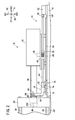
- FIG. 1 is a schematic diagram showing the configuration of an injection molding machine 1
- FIG. 2 is a schematic diagram showing a part of the injection molding machine 1 in an injection state.
- D1 in the figure is in the front-rear direction
- D2 in the figure is in the vertical direction
- D3 in the figure is in the left-right direction.
- the front-rear direction D1, the vertical direction D2, and the horizontal direction D3 are orthogonal to each other.
- D11 in the figure is in the forward direction
- D12 in the figure is in the rear direction
- D21 in the figure is in the upward direction
- D22 in the figure is in the downward direction.
- the downward direction D22 may be a direction in which gravity acts, or may be a direction different from the direction in which gravity acts.
- the injection molding machine 1 includes a machine base 10, a mold clamping unit 12, an injection unit 14, a nozzle touch mechanism 16, and a connecting member 18.
- the machine base 10 is a base for mounting the mold clamping unit 12, the injection unit 14, the nozzle touch mechanism 16, and the connecting member 18, and has a mounting surface 10F.
- the mounting surface 10F on which the mold clamping unit 12 is mounted may be on the same surface as the mounting surface 10F on which the injection unit 14, the nozzle touch mechanism 16 and the connecting member 18 are mounted, and the mounting surface 10F is displaced in the vertical direction D2. May be good.
- the mounting surface 10F on which the mold clamping unit 12 is mounted and the mounting surface 10F on which the injection unit 14, the nozzle touch mechanism 16 and the connecting member 18 are mounted may be displaced in the vertical direction D2. Illustrated.
- the first machine base for mounting the mold clamping unit 12 and the second machine base for mounting the injection unit 14, the nozzle touch mechanism 16 and the connecting member 18 are separably connected. May be good.
- the first machine and the second machine are separably connected, for example, the connected first machine and the second machine can be separated at the time of maintenance. Therefore, access to the mold clamping unit 12 and the injection unit 14 and the like becomes easy, and maintenance of the mold clamping unit 12 and the injection unit 14 and the like can be performed individually.
- the mold clamping unit 12 has a fixed platen 20, a rear platen 22, a movable platen 24, a mold 26, a plurality of tie bars 28, and a platen drive mechanism 29.
- the fixed platen 20 and the rear platen 22 are installed on the mounting surface 10F of the machine base 10 of the injection molding machine 1 at intervals from each other.
- a nozzle insertion hole 20H is formed in the fixed platen 20.
- the movable platen 24 is arranged between the fixed platen 20 and the rear platen 22.
- the mold 26 is composed of a fixed mold 26A and a movable mold 26B. The fixed mold 26A is attached to the movable platen 24 side of the fixed platen 20, and the movable mold 26B is attached to the fixed platen 20 side of the movable platen 24.
- Each of the plurality of tie bars 28 is a rod-shaped member, one of both ends of the tie bar 28 is fixed to the fixed platen 20, and the other of both ends of the tie bar 28 is fixed to the rear platen 22.
- a movable platen 24 penetrates each of the plurality of tie bars 28, and the movable platen 24 can move along the tie bar 28.
- the platen drive mechanism 29 closes the mold 26 by moving the movable platen 24 in the platen approaching direction (rear direction D12) in which the movable platen 24 approaches the fixed platen 20.
- the platen drive mechanism 29 opens the mold 26 by moving the movable platen 24 in the platen separation direction (forward direction D11) at which the movable platen 24 is separated from the fixed platen 20.
- the movable mold 26B In the state where the mold 26 is clamped, the movable mold 26B is in contact with the fixed mold 26A, and when the mold 26 is opened, the movable mold 26B is not in contact with the fixed mold 26A. It is a contact.
- the injection unit 14 has a base portion 40, an injection unit main body 42, a cylinder portion 44, and a nozzle 46.
- the base portion 40 is a basic portion of the injection unit 14, and is slidably attached to a plurality of guide rails 50 provided on the mounting surface 10F of the machine base 10.
- the plurality of guide rails 50 extend in parallel along the front-rear direction D1 at regular intervals in the left-right direction D3.
- the injection unit main body 42 is placed on the base portion 40 and is rotatably connected to the base portion 40 with the swivel pin 48 as the center of rotation.
- the cylinder portion 44 is fixed to the injection unit main body 42, and extends from the surface of the injection unit main body 42 on the fixed platen 20 side toward the mold clamping unit 12 along the guide rail 50.
- the nozzle 46 is for ejecting the molten material, and extends from the tip of the cylinder portion 44 toward the mold clamping unit 12 along the guide rail 50.
- the injection unit 14 can move along the plurality of guide rails 50 in the first direction (forward direction D11) approaching the mold 26 and in the second direction (rear direction D12) away from the mold 26. Is.
- the injection unit 14 moves in the forward direction D11 or the backward direction D12 by the nozzle touch mechanism 16.
- the nozzle touch mechanism 16 has a motor 52, a ball screw shaft 54, and a ball screw nut 56.
- the motor 52 is a motor for moving the injection unit 14 in the forward direction D11 or the backward direction D12.
- the ball screw shaft 54 extends along the front-rear direction D1.
- the rear end of the ball screw shaft 54 is connected to the rotor shaft of the motor 52 via the coupling 58, and the front end of the ball screw shaft 54 is connected to the connecting member 18.
- the ball screw nut 56 is screwed into the ball screw shaft 54 and is connected to the base portion 40 via a spring 60 so as to be non-rotatable with respect to the base portion 40 of the injection unit main body 42.
- the spring 60 may be omitted.
- the nozzle touch mechanism 16 drives the motor 52 in the reverse rotation direction (or forward rotation direction) when the injection unit 14 is moved in the backward direction D12 with respect to the machine base 10.
- the motor 52 is driven in the reverse rotation direction (or forward rotation direction)
- the ball screw shaft 54 connected to the rotor shaft of the motor 52 rotates, and the ball screw nut 56 screwed to the ball screw shaft 54 moves to the rear D12. Moving.
- the injection unit 14 moves in the rear direction D12.
- the nozzle touch mechanism 16 drives the motor 52 in the forward rotation direction (or reverse rotation direction) when the injection unit 14 is moved in the forward direction D11 with respect to the machine base 10.
- the motor 52 is driven in the forward rotation direction (or reverse rotation direction)
- the ball screw shaft 54 connected to the rotor shaft of the motor 52 rotates, and the ball screw nut 56 screwed to the ball screw shaft 54 moves in the forward direction D11.
- the injection unit 14 moves in the forward direction D11.
- the nozzle 46 of the injection unit 14 is inserted into the nozzle insertion hole 20H of the fixed platen 20, and the nozzle contact portion of the mold 26 is inserted through the nozzle insertion hole 20H. Contact the spool) (see FIG. 2).
- the nozzle touch mechanism 16 moves the injection unit 14 in the forward direction D11 with respect to the machine base 10 to press the nozzle 46 of the injection unit 14 against the mold 26. .. That is, the nozzle touch mechanism 16 drives the motor 52 in the forward rotation direction (or reverse rotation direction) even after the nozzle 46 comes into contact with the nozzle contact portion (spool) of the mold 26, thereby pushing the ball screw nut 56 forward. Move to D11. As a result, the spring 60 is compressed, and the injection unit 14 is in a nozzle touch state in which the nozzle 46 is pressed against the spool of the mold 26 by the compression reaction force.
- the injection unit 14 When the spring 60 is omitted, the injection unit 14 is brought into the nozzle touch state by continuing to drive the motor 52 in the forward rotation direction (or reverse rotation direction). In addition, when the spring 60 is provided, the nozzle touch state can be maintained even if the motor 52 is stopped while the spring 60 is compressed. The injection unit 14 injects a molten resin or metal material into the mold 26 in a nozzle-touch state.
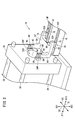
- FIG. 3 is a perspective view showing the connecting member 18.
- the connecting member 18 has a support base portion 62 and a pair of arm portions 64, and is formed in a substantially L-shape in side view.
- the support base portion 62 is slidable in the forward direction D11 or the backward direction D12 with respect to the machine base 10, and is supported by the machine base 10 via the linear motion mechanism 70.
- the linear motion mechanism 70 is for the support base portion 62 to slide in the forward direction D11 or the backward direction D12 with respect to the machine base 10, and has a plurality of support rails 72 and a plurality of guide blocks 74.
- Each of the plurality of support rails 72 extends along the front-rear direction D1.
- the number of support rails 72 may be two or three or more as illustrated in FIG.
- the plurality of support rails 72 are arranged at regular intervals in the left-right direction D3.
- the left-right direction D3 coincides with the width direction of the machine base 10.
- the width direction of the machine base 10 is parallel to the mounting surface 10F of the machine base 10 and is orthogonal to the first direction (forward direction D11) in which the injection unit 14 approaches the mold 26.
- Each of the plurality of guide blocks 74 is slidably engaged with the support rail 72.
- One or more guide blocks 74 are provided for one support rail 72.
- the guide blocks 74 are arranged at intervals in the front-rear direction D1. In the example of FIG. 3, two guide blocks 74 are provided for one support rail 72.
- the support base portion 62 may have a pair of protruding leg portions 62A that protrude from both ends of the left-right direction D3 toward the injection unit 14 side (rear direction D12 side). Each protruding leg portion 62A is arranged directly above the support rail 72, and projects from the support base portion 62 along the support rail 72.
- a bearing portion 66 is provided on the end surface of the support base portion 62 on the injection unit 14 side (rear direction D12 side) between the pair of protruding leg portions 62A. The other end of the ball screw shaft 54 of the nozzle touch mechanism 16 is attached to the bearing portion 66.
- the bearing portion 66 is a portion connected to the nozzle touch mechanism 16, and in the present embodiment, the case where the bearing portion 66 is retracted toward the fixed platen 20 side from the pair of protruding leg portions 62A is exemplified.
- the pair of arm portions 64 stands up from the fixed platen 20 side (front direction D11 side) of the support base portion 62 upward (upward direction D21) at intervals in the left-right direction D3. In the case of the present embodiment, the pair of arm portions 64 rise upward (upward D21) from the support base portion 62 along the surface of the injection unit 14 side (rear direction D12 side) of the fixed platen 20. ing.
- Each of the pair of arm portions 64 has a platen connecting portion 80 connected to the fixed platen 20 on the upper portion of the arm portion 64 rising from the support base portion 62.
- Each platen connecting portion 80 is provided so as to be symmetrical with the nozzle 46 interposed therebetween. Since the configuration of each platen connecting portion 80 is the same, the configuration of one platen connecting portion 80 will be described below.
- the platen connecting portion 80 is connected to the fixed platen 20 in a state of being rotatable with respect to the fixed platen 20.
- the platen connecting portion 80 has a notch portion 82, a connecting pin 84, and a rotating member 86.
- the notch 82 is a notched portion in the upper part of the arm 64.
- the cutout portion 82 is located substantially in the middle of both ends in the width direction (horizontal direction D3) of the arm portion 64, and is located from the end surface on the fixed platen 20 side (front direction D11 side) to the injection unit 14 side (rear direction D12 side). It extends in the anteroposterior direction D1 over the end face.
- the connecting pin 84 is arranged in the notch 82 and extends in the left-right direction D3.
- the connecting pin 84 is fixed to the arm portion 64 in the left-right direction D3 of the notch portion 82. That is, the connecting pin 84 is in a state in which it cannot rotate with respect to the arm portion 64 and cannot slide with respect to the arm portion 64 in any of the front-rear direction D1, the vertical direction D2, and the left-right direction D3.
- the rotating member 86 is fixed to the fixed platen 20 in a state of being rotatable around the connecting pin 84.
- FIG. 4 is a schematic diagram showing the relationship between the connecting member 18 and the nozzle 46 of the injection unit 14.
- the connecting pin 84 of the connecting member 18 is located at substantially the same height as the nozzle 46 of the injection unit 14. That is, the connecting pin 84 is arranged so as to pass through the central axis of the nozzle 46 and include the surface F1 parallel to the mounting surface 10F of the machine base 10. It is preferable that the pin axis AX of the connecting pin 84 is located on the surface F1. Since the connecting pin 84 is arranged so as to include the above-mentioned surface F1, the rotating member 86 rotatable around the connecting pin 84 is also arranged so as to include the above-mentioned surface F1.
- the height of the connecting pin 84 is the height from the mounting surface 10F of the machine base 10 (the length from the mounting surface 10F to the upward D21).
- the central axis of the nozzle 46 is a line passing through the radial center of the nozzle 46 along the direction in which the nozzle 46 extends.
- FIG. 5 is a schematic diagram showing the state of force generation in the comparative example.
- This comparative example assumes the above-mentioned Japanese Patent Application Laid-Open No. 2019-025701.
- the connecting member 18EX is provided instead of the connecting member 18 of the present embodiment.
- the connecting member 18EX has a platen connecting portion 80EX different from the platen connecting portion 80 of the present embodiment, and a rotating member 86EX different from the rotating member 86 of the present embodiment.
- the platen connecting portion 80EX passes through the central axis of the nozzle 46, and the connecting pin 84EX is arranged on the machine base 10 side (downward D22 side) with respect to the surface F1 parallel to the mounting surface 10F of the machine base 10.
- the rotating member 86EX has a shape different from the shape of the rotating member 86 of the present embodiment.
- the configurations other than the platen connecting portion 80EX and the rotating member 86EX are the same as those in the present embodiment.
- the nozzle touch force P2 is generated on the connecting member 18EX as a reaction force of the pressing force P1.
- the connecting member 18EX since the support base portion 62 of the platen connecting portion 80EX can slide in the forward direction D11 or the backward direction D12 with respect to the machine base 10, mainly the nozzle touch force is applied to the connecting pin 84EX of the connecting member 18EX. P2 is generated.
- the connecting pin 84EX passes through the central axis of the nozzle 46 and is arranged on the machine base 10 side (downward D22 side) with respect to the surface F1 parallel to the mounting surface 10F of the machine base 10. Therefore, the lines of action of the pressing force P1 and the nozzle touch force P2 of the reaction force are not on the same straight line. Therefore, the moment MF is generated in the direction in which the fixed platen 20 collapses.
- FIG. 6 is a schematic diagram showing a state of force generation according to the present embodiment.
- the connecting pin 84 is arranged so as to pass through the central axis of the nozzle 46 and include a surface F1 parallel to the mounting surface 10F of the machine base 10. Therefore, the line of action of the pressing force P1 and the nozzle touch force P2 of the reaction force are on the same straight line. Therefore, the moment MF is almost not generated in the direction in which the fixed platen 20 falls, and the effect of preventing the fixed platen 20 from falling can be improved by the connecting member 18. In this embodiment, even if the connecting member 18 is tilted toward the fixed platen 20, the moment MF generated by the tilting can be converted into the rotation of the platen connecting portion 80.
- FIG. 7 is a front view of the platen connecting portion 80 as viewed from the injection unit 14 side.
- the pair of platen connecting portions 80 pass through the central axis of the nozzle 46 and are provided symmetrically with respect to the surface F2 orthogonal to the mounting surface 10F of the machine base 10.
- the connection between the fixed platen 20 and the connecting member 18 can be strengthened as compared with the case where the platen connecting portion 80 is one, and the variation in the force acting on each of the platen connecting portions 80 is suppressed. be able to.
- each platen connecting portion 80 is located on both the machine base 10 side (downward D22 side) and the side opposite to the machine base 10 side (upward D21 side) with the connecting pin 84 interposed therebetween. It is fixed to the fixing platen 20 by a plurality of first fasteners 90. As a result, it is effective that the connecting member 18 is tilted toward the fixed platen 20 as compared with the case where the rotating member 86 is fixed to the fixed platen 20 on one side and the other side of the left-right direction D3 with the connecting pin 84 interposed therebetween. Can be suppressed.
- the first fastener 90 is an instrument for fixing the object to be fixed to the object to be fixed, and examples of the first fastener 90 include bolts and the like.
- the plurality of first fasteners 90 pass through the central axis of the nozzle 46 and are provided symmetrically with respect to the surface F1 parallel to the mounting surface 10F of the machine base 10. As a result, it is possible to suppress variations in the force acting on each of the plurality of first fasteners 90.
- a pair of pedestal portions 20P are provided on the surface of the fixed platen 20 on the injection unit 14 side, and one rotating member 86 of the platen connecting portion 80 is provided for each pedestal portion 20P as two first fasteners. It is fixed by 90. Further, the rotating member 86 of each platen connecting portion 80 has a portion slightly protruding toward the fixed platen 20 with respect to the arm portion 64. Therefore, in a state where the rotating member 86 is fixed to the pedestal portion 20P, a predetermined gap GP is formed between the fixed platen 20 and the arm portion 64 (FIG. 4). That is, the connecting member 18 and the fixed platen 20 do not interfere with each other except for the rotating member 86 and the pedestal portion 20P. Therefore, it is possible to suppress the heat of the molten material or the like injected into the mold 26 from being conducted to the connecting member 18 via the fixed platen 20.
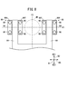
- FIG. 8 is a schematic view showing the platen connecting portion 80 of the modified example 1. Since the configuration of the pair of platen connecting portions 80 of this modification is the same, the configuration of one platen connecting portion 80 will be described as in the embodiment.
- the platen connecting portion 80 has a pair of rotating members 86X and 86Y instead of the rotating member 86 of the embodiment.
- the pair of rotating members 86X and 86Y may or may not be connected to each other.
- FIG. 8 illustrates a case where the pair of rotating members 86X and 86Y are not connected.
- the rotating member 86X is fixed to the fixed platen 20 in a state where it can rotate about a connecting pin 84 protruding from one of both ends in the width direction (horizontal direction D3) of the arm portion 64.
- the rotating member 86Y is fixed to the fixed platen 20 in a state of being rotatable about a connecting pin 84 protruding from the other of both ends in the width direction (horizontal direction D3) of the arm portion 64.
- the rotating member 86X and the rotating member 86Y are on the machine base 10 side (downward D22 side) and on the side opposite to the machine base 10 side (upward D21 side) with the connecting pin 84 interposed therebetween. Both are secured by a plurality of first fasteners 90. Similar to the embodiment, these first fasteners 90 are provided symmetrically with respect to the surface F1 passing through the central axis of the nozzle 46 and parallel to the mounting surface 10F of the machine base 10.
- the platen connecting portion 80 of the present modification is different from the configuration of the platen connecting portion 80 of the embodiment, it is rotatable with respect to the fixed platen 20 like the platen connecting portion 80 of the embodiment. It is connected to the fixed platen 20. Therefore, as in the embodiment, even if the connecting member 18 is tilted toward the fixed platen 20, the moment MF generated by the tilting can be converted into the rotation of the platen connecting portion 80.
- the pedestal portion 20P (see FIG. 3) for the rotating member 86X and the rotating member 86Y may be provided on the surface of the fixed platen 20 on the injection unit 14 side, or may be omitted. Further, the rotating member 86X and the rotating member 86Y may have a portion slightly protruding toward the fixed platen 20 from the arm portion 64, as in the embodiment. When the rotating member 86X and the rotating member 86Y have a portion protruding toward the fixed platen 20 from the arm portion 64, a predetermined gap GP (FIG. 4) is provided between the fixed platen 20 and the arm portion 64 as in the embodiment. ) Is formed. Therefore, similarly to the embodiment, it is possible to suppress the heat of the molten material or the like injected into the mold 26 from being conducted to the connecting member 18 via the fixed platen 20.
- the number of platen connecting portions 80 and arm portions 64 may be one or three or more. From the viewpoint of suppressing the variation in the force acting on each of the platen connecting portions 80, as shown in FIG. 7, the plurality of platen connecting portions 80 and the arm portions 64 pass through the central axis of the nozzle 46 and the machine base. It is preferable that the surface 10 is provided symmetrically with respect to the surface F2 orthogonal to the mounting surface 10F.
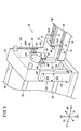
- FIG. 9 is a schematic view showing the injection molding machine 1 of the modification 2 from the same viewpoint as that of FIG. In this modification, at least two fixed platen support portions 100 that support both sides of the fixed platen 20 in the left-right direction D3 are provided. Note that FIG. 9 shows one fixed platen support 100 that supports the right side (or left side) of the fixed platen 20 and one fixed platen support 100 that supports the left side (or right side) of the fixed platen 20. ing.
- Each fixed platen support portion 100 and fixed platen 20 are provided symmetrically with respect to a surface F2 (see FIG. 7) that passes through the central axis of the nozzle 46 and is orthogonal to the mounting surface 10F of the machine base 10. Thereby, the variation of the force generated in the contact portion between the fixed platen support portion 100 and the fixed platen 20 can be suppressed, and the fixed platen 20 can be stably supported by each of the fixed platen support portions 100.
- the fixed platen 20 supported by each fixed platen support portion 100 may be non-contact with the machine base 10.
- FIG. 9 shows a case where the fixed platen 20 is not in contact with the machine base 10.
- the fixed platen 20 is opposite to the machine base 10 side (downward D22 side) and the machine base 10 as compared with the case where the fixed platen 20 is in contact with the machine base 10. It becomes difficult to deform asymmetrically with the side (upward D21 side). That is, when the fixed platen 20 is not in contact with the machine base 10, even if the fixed platen 20 expands due to heat conducted from the mold 26 or the like, the fixed platen 20 is less likely to be deformed asymmetrically in the vertical direction D2.
- FIG. 10A is a front view of one fixed platen support portion 100 from one side surface side of the fixed platen 20 in the left-right direction D3
- FIG. 10B is a front view of the fixed platen support portion 100 from the injection unit 14 side. It is a figure.
- the fixed platen support portion 100 has a support main body 102 and a protruding portion 104 slightly protruding toward the fixed platen 20 with respect to the support main body 102.
- the fixed platen support portion 100 is fixed to the fixed platen 20 in a state where the protruding portion 104 is in contact with the side surface of the fixed platen 20 in the left-right direction D3.
- a predetermined gap GP1 is formed between the fixed platen support portion 100 other than the protruding portion 104 and the fixed platen 20. That is, the fixed platen support portion 100 does not interfere with the fixed platen 20 except for the protruding portion 104. Therefore, when a predetermined gap GP1 is formed between the fixed platen support portion 100 and the fixed platen 20, the fixed platen 20 is tilted in the tilting direction by the connecting member 18 as compared with the case where the gap GP1 is not formed. Can be further suppressed.
- the fixed platen support portion 100 is fixed to the fixed platen 20 by a plurality of second fasteners 106.
- the second fastener 106 is an instrument for fixing the object to be fixed to the object to be fixed, and examples of the second fastener 106 include bolts and the like.
- the second fastener 106 may have the same configuration as the first fastener 90 or may have a different configuration.
- the plurality of second fasteners 106 pass through the central axis of the nozzle 46 and are provided symmetrically with respect to the surface F1 parallel to the mounting surface 10F of the machine base 10. Further, the plurality of second fasteners 106 pass through the thickness center of the fixed platen 20 in the front-rear direction D1 and are provided symmetrically with respect to the surface F3 orthogonal to the mounting surface 10F of the machine base 10. As a result, it is possible to suppress variations in the force acting on each of the plurality of second fasteners 106.
- the height H of the fixed platen support portion 100 from the machine base 10 may pass through the central axis of the nozzle 46 and exceed the surface F1 parallel to the mounting surface 10F of the machine base 10.
- the collapse of the fixed platen 20 by the connecting member 18 is firmer than when the height H does not exceed the above-mentioned surface F1. It can be suppressed stably.
- the present invention is an injection molding machine (1) having an injection unit (14), a machine base (10), a nozzle touch mechanism (16), and a connecting member (18).
- the injection unit (14) has a nozzle (46) for injecting the molten material into a fixed platen (20) and a mold (26) fixed to the movable platen (24).
- the injection unit (14) is mounted on the machine base (10).
- the nozzle touch mechanism (16) makes the nozzle (46) gold by moving the injection unit (14) in the first direction (D11) approaching the mold (26) with respect to the machine base (10). Press against the mold (26).
- the connecting member (18) can slide in the first direction (D11) and the second direction (D12) opposite to the first direction (D11) with respect to the machine base (10), and the nozzle touch mechanism (18) 16) and the fixed platen (20) are connected.
- the connecting member (18) has a support base portion (62) that is slidably attached to the machine base (10) and an arm portion (64) that rises upward from the fixed platen (20) side of the support base portion (62).
- the support base portion (62) has a first connecting portion (66) to be connected to the nozzle touch mechanism (16), and the fixed platen (20) is provided on the upper portion of the arm portion (64). It has a second connecting portion (80) to be connected.
- the second connecting portion (80) of the connecting member (18) is fixed to the arm portion (64), is parallel to the mounting surface (10F) of the machine base (10), and is orthogonal to the first direction (D11). It has a connecting pin (84) extending in the width direction (D3) of the machine base (10) and a rotating member (86) fixed to the fixed platen (20) and rotatable about the connecting pin (84).
- the connecting pin (84) is arranged so as to pass through the central axis of the nozzle (46) and include a surface (F1) parallel to the mounting surface (10F) of the machine base (10).
- the connecting pin (84) is connected so as not to include the surface (F1) that passes through the central axis of the nozzle (46) and is parallel to the mounting surface (10F) of the machine base (10).
- the inclination of the member (18) can be suppressed.
- the moment (MF) generated by the tilting can be converted into the rotation of the second connecting portion (80).
- the effect of preventing the fixed platen (20) from collapsing by the connecting member (18) can be improved.
- the injection molding machine (1) is provided on the machine base (10), and the support base portion (62) slides in the first direction (D11) or the second direction (D12) with respect to the machine base (10).
- a linear motion mechanism (70) may be further provided, and the support base portion (62) may be supported by the machine base (10) via the linear motion mechanism (70). This facilitates stable sliding of the connecting member (18).
- the rotating member (86) may be fixed to the fixed platen (20) on both the machine base (10) side and the side opposite to the machine base (10) side with the connecting pin (84) interposed therebetween.
- the rotating member (86) is fixed to the fixed platen (20) on one side and the other side in the width direction (D3) of the machine base (10) with the connecting pin (84) interposed therebetween. It is possible to effectively prevent the connecting member (18) from tilting toward the fixed platen (20).
- the rotating member (86) is fixed to the fixed platen (20) by a plurality of first fasteners (90), and the plurality of first fasteners (90) pass through the central axis of the nozzle (46) and the machine base (20). It may be provided symmetrically with respect to the surface (F1) parallel to the mounting surface (10F) of 10). As a result, it is possible to suppress variations in the force acting on each of the plurality of first fasteners (90).
- the second connecting portion (80) may be provided symmetrically with respect to a surface (F2) that passes through the central axis of the nozzle (46) and is orthogonal to the mounting surface (10F) of the machine base (10).
- a surface (F2) that passes through the central axis of the nozzle (46) and is orthogonal to the mounting surface (10F) of the machine base (10).
- the connecting pin (84) may be fixed so that it cannot rotate with respect to the arm portion (64) and cannot slide with respect to the arm portion (64) in the pin axis (AX) direction.
- the moment (MF) generated by tilting the connecting member (18) toward the fixed platen (20) can be effectively converted by the rotation of the second connecting portion (80).
- the injection molding machine (1) is provided on the machine base (10) and has at least two fixed platen support portions (100) that support both sides of the fixed platen (20) in the width direction (D3) of the machine base (10). You may also prepare further. As a result, the inclination of the fixed platen (20) in the tilting direction due to the connecting member (18) can be further suppressed as compared with the case where the fixed platen support portion (100) is not provided.
- the fixed platen (20) may be non-contact with the machine base (10). This reduces the asymmetrical deformation of the fixed platen (20) between the machine base (10) side and the opposite side even if the fixed platen (20) expands due to heat conducted from the mold (26). can do. Therefore, even if the connecting member (18) is tilted toward the fixed platen (20), a moment (MF) is less likely to be generated in the direction in which the fixed platen (20) is tilted. As a result, the effect of preventing the fixed platen (20) from collapsing by the connecting member (18) can be further improved.
- the fixed platen (20) and each fixed platen support (100) pass through the central axis of the nozzle (46) and are symmetrical with respect to the plane (F2) orthogonal to the mounting surface (10F) of the machine base (10). It may be provided. As a result, it is possible to suppress variations in the force generated at the contact portion between the fixed platen (20) and the fixed platen support portion (100), and each of the fixed platen support portions (100) stabilizes the fixed platen (20). Can be supported.
- Each fixed platen support (100) is fixed to the fixed platen (20) by a plurality of second fasteners (106), and the plurality of second fasteners (106) pass through the central axis of the nozzle (46). , May be provided symmetrically with respect to a surface (F1) parallel to the mounting surface (10F) of the machine base (10). As a result, it is possible to suppress variations in the force acting on each of the plurality of second fasteners (106).
- the plurality of second fasteners (106) pass through the thickness center of the fixed platen (20) in the first direction (D11) and with respect to the surface (F3) orthogonal to the mounting surface (10F) of the machine base (10). It may be provided symmetrically. As a result, it is possible to suppress variations in the force acting on each of the plurality of second fasteners (106).
Landscapes
- Engineering & Computer Science (AREA)
- Mechanical Engineering (AREA)
- Manufacturing & Machinery (AREA)
- Injection Moulding Of Plastics Or The Like (AREA)
- Moulds For Moulding Plastics Or The Like (AREA)
Abstract
Description
固定プラテンおよび可動プラテンに固定された金型の内部に溶融材料を射出するノズルを有する射出ユニットと、
前記射出ユニットが搭載される機台と、
前記機台に対して、前記金型に接近する第1方向に、前記射出ユニットを移動させることにより、前記ノズルを前記金型に押し付けるノズルタッチ機構と、
前記機台に対して、前記第1方向と前記第1方向とは逆の第2方向とにスライド可能であり、前記ノズルタッチ機構と前記固定プラテンとを連結する連結部材と、
を備える射出成形機であって、
前記連結部材は、前記機台に対してスライド可能に取り付けられる支持台部と、前記支持台部の前記固定プラテン側から上方に立ち上がる腕部とを有し、前記支持台部に、前記ノズルタッチ機構と連結される第1の連結部を有すると共に、前記腕部の上部に、前記固定プラテンと連結される第2の連結部を有し、
前記連結部材の前記第2の連結部は、前記腕部に固定され、前記機台の搭載面と平行であって前記第1方向に直交する前記機台の幅方向に延びる連結ピンと、前記固定プラテンに固定され、前記連結ピンを中心にして回転可能な回転部材とを有し、
前記連結ピンは、前記ノズルの中心軸を通り、前記機台の搭載面と平行する面を含むように配置される。
[射出成形機の構成]
図1は射出成形機1の構成を示す模式図であり、図2は射出状態における射出成形機1の一部を示す模式図である。本実施形態では、図中のD1は前後方向とし、図中のD2は上下方向とし、図中のD3は左右方向とする。なお、前後方向D1、上下方向D2および左右方向D3は互いに直交する関係にある。また、本実施形態では、図中のD11は前方向とし、図中のD12は後方向とし、図中のD21は上方向とし、図中のD22は下方向とする。なお、下方向D22は、重力が働く方向であってもよく、重力が働く方向とは異なる方向であってもよい。
上記の実施形態は、下記のように変形してもよい。
図8は、変形例1のプラテン連結部80を示す模式図である。本変形例の一対のプラテン連結部80の構成は同じであるため、実施形態と同様に、1つのプラテン連結部80の構成に関して説明する。
プラテン連結部80および腕部64の数は1つであってもよく、3以上であってもよい。なお、プラテン連結部80の各々に作用する力のばらつきを抑制する観点では、図7に示したように、複数のプラテン連結部80および腕部64が、ノズル46の中心軸を通り、機台10の搭載面10Fに直交する面F2に対して対称に設けられることが好ましい。
図9は、変形例2の射出成形機1を図3と同じ視点で示す模式図である。本変形例では、左右方向D3における固定プラテン20の両側を支持する少なくとも2つの固定プラテン支持部100が備えられる。なお、図9では、固定プラテン20の右側(または左側)を支持する1つの固定プラテン支持部100と、固定プラテン20の左側(または右側)を支持する1つの固定プラテン支持部100とが示されている。
上記の実施形態および変形例は、矛盾の生じない範囲で任意に組み合わされてもよい。
上記の実施形態および変形例から把握しうる発明について、以下に記載する。
Claims (12)
- 固定プラテン(20)および可動プラテン(24)に固定された金型(26)の内部に溶融材料を射出するノズル(46)を有する射出ユニット(14)と、
前記射出ユニットが搭載される機台(10)と、
前記機台に対して、前記金型に接近する第1方向(D11)に、前記射出ユニットを移動させることにより、前記ノズルを前記金型に押し付けるノズルタッチ機構(16)と、
前記機台に対して、前記第1方向と前記第1方向とは逆の第2方向(D12)とにスライド可能であり、前記ノズルタッチ機構と前記固定プラテンとを連結する連結部材(18)と、
を備える射出成形機(1)であって、
前記連結部材は、前記機台に対してスライド可能に取り付けられる支持台部(62)と、前記支持台部の前記固定プラテン側から上方に立ち上がる腕部(64)とを有し、前記支持台部に、前記ノズルタッチ機構と連結される第1の連結部(66)を有すると共に、前記腕部の上部に、前記固定プラテンと連結される第2の連結部(80)を有し、
前記連結部材の前記第2の連結部は、前記腕部に固定され、前記機台の搭載面(10F)と平行であって前記第1方向に直交する前記機台の幅方向(D3)に延びる連結ピン(84)と、前記固定プラテンに固定され、前記連結ピンを中心にして回転可能な回転部材(86)とを有し、
前記連結ピンは、前記ノズルの中心軸を通り、前記機台の搭載面と平行する面(F1)を含むように配置される、射出成形機。 - 請求項1に記載の射出成形機であって、
前記機台に設けられ、前記支持台部が前記機台に対して前記第1方向または前記第2方向にスライドするための直動機構(70)をさらに備え、
前記支持台部は、前記直動機構を介して前記機台に支持される、射出成形機。 - 請求項1または2に記載の射出成形機であって、
前記回転部材は、前記連結ピンを挟んで前記機台側および前記機台側とは反対側との両方で、前記固定プラテンに固定される、射出成形機。 - 請求項1~3のいずれか1項に記載の射出成形機であって、
前記回転部材は、複数の第1締結具(90)により前記固定プラテンに固定され、
前記複数の第1締結具は、前記ノズルの中心軸を通り、前記機台の搭載面と平行する面に対して対称に設けられる、射出成形機。 - 請求項1~4のいずれか1項に記載の射出成形機であって、
前記第2の連結部は、前記ノズルの中心軸を通り、前記機台の搭載面に直交する面(F2)に対して対称に設けられる、射出成形機。 - 請求項1~5のいずれか1項に記載の射出成形機であって、
前記連結ピンは、前記腕部に対して回転不能、かつ、前記腕部に対してピン軸方向にスライド不能となるように固定されている、射出成形機。 - 請求項1~6のいずれか1項に記載の射出成形機であって、
前記機台に設けられ、前記機台の幅方向における前記固定プラテンの両側を支持する少なくとも2つの固定プラテン支持部(100)をさらに備える、射出成形機。 - 請求項7に記載の射出成形機であって、
各々の前記固定プラテン支持部における前記機台の搭載面からの高さ(H)は、前記ノズルの中心軸を通り、前記機台の搭載面と平行する面を超えている、射出成形機。 - 請求項7または8に記載の射出成形機であって、
前記固定プラテンは、前記機台と非接触である、射出成形機。 - 請求項7~9のいずれか1項に記載の射出成形機であって、
前記固定プラテンおよび各々の前記固定プラテン支持部は、前記ノズルの中心軸を通り、前記機台の搭載面に直交する面に対して対称に設けられる、射出成形機。 - 請求項7~10のいずれか1項に記載の射出成形機であって、
各々の前記固定プラテン支持部は、複数の第2締結具(106)により前記固定プラテンに固定され、
前記複数の第2締結具は、前記ノズルの中心軸を通り、前記機台の搭載面と平行する面に対して対称に設けられる、射出成形機。 - 請求項11に記載の射出成形機であって、
前記複数の第2締結具は、前記第1方向における前記固定プラテンの厚さ中心を通り、前記機台の搭載面に直交する面(F3)に対して対称に設けられる、射出成形機。
Priority Applications (4)
| Application Number | Priority Date | Filing Date | Title |
|---|---|---|---|
| CN202180038269.7A CN115666897B (zh) | 2020-05-28 | 2021-05-24 | 注射成型机 |
| DE112021002991.6T DE112021002991B4 (de) | 2020-05-28 | 2021-05-24 | Spritzgießmaschine |
| US17/926,527 US12350871B2 (en) | 2020-05-28 | 2021-05-24 | Injection molding machine |
| JP2021538469A JP6947957B1 (ja) | 2020-05-28 | 2021-05-24 | 射出成形機 |
Applications Claiming Priority (2)
| Application Number | Priority Date | Filing Date | Title |
|---|---|---|---|
| JP2020-093311 | 2020-05-28 | ||
| JP2020093311 | 2020-05-28 |
Publications (1)
| Publication Number | Publication Date |
|---|---|
| WO2021241464A1 true WO2021241464A1 (ja) | 2021-12-02 |
Family
ID=78744416
Family Applications (1)
| Application Number | Title | Priority Date | Filing Date |
|---|---|---|---|
| PCT/JP2021/019488 Ceased WO2021241464A1 (ja) | 2020-05-28 | 2021-05-24 | 射出成形機 |
Country Status (1)
| Country | Link |
|---|---|
| WO (1) | WO2021241464A1 (ja) |
Cited By (1)
| Publication number | Priority date | Publication date | Assignee | Title |
|---|---|---|---|---|
| WO2024161475A1 (ja) * | 2023-01-30 | 2024-08-08 | ファナック株式会社 | 射出成形機 |
Citations (7)
| Publication number | Priority date | Publication date | Assignee | Title |
|---|---|---|---|---|
| JP2001038764A (ja) * | 1999-08-02 | 2001-02-13 | Fanuc Ltd | 射出成形機 |
| US20060127528A1 (en) * | 2003-08-14 | 2006-06-15 | Demag Ergotech Gmbh | Nozzle contact device |
| JP2008238769A (ja) * | 2007-03-29 | 2008-10-09 | Niigata Machine Techno Co Ltd | 射出成形機の型締装置 |
| JP2010241076A (ja) * | 2009-04-09 | 2010-10-28 | Fanuc Ltd | ノズルタッチ機構部を備えた射出成形機 |
| JP2012011767A (ja) * | 2009-12-17 | 2012-01-19 | Toshiba Mach Co Ltd | 射出成形機 |
| WO2014007329A1 (ja) * | 2012-07-05 | 2014-01-09 | 東芝機械株式会社 | ノズルタッチ機構および射出成形機 |
| JP2019025701A (ja) * | 2017-07-27 | 2019-02-21 | ファナック株式会社 | 射出成形機 |
-
2021
- 2021-05-24 WO PCT/JP2021/019488 patent/WO2021241464A1/ja not_active Ceased
Patent Citations (7)
| Publication number | Priority date | Publication date | Assignee | Title |
|---|---|---|---|---|
| JP2001038764A (ja) * | 1999-08-02 | 2001-02-13 | Fanuc Ltd | 射出成形機 |
| US20060127528A1 (en) * | 2003-08-14 | 2006-06-15 | Demag Ergotech Gmbh | Nozzle contact device |
| JP2008238769A (ja) * | 2007-03-29 | 2008-10-09 | Niigata Machine Techno Co Ltd | 射出成形機の型締装置 |
| JP2010241076A (ja) * | 2009-04-09 | 2010-10-28 | Fanuc Ltd | ノズルタッチ機構部を備えた射出成形機 |
| JP2012011767A (ja) * | 2009-12-17 | 2012-01-19 | Toshiba Mach Co Ltd | 射出成形機 |
| WO2014007329A1 (ja) * | 2012-07-05 | 2014-01-09 | 東芝機械株式会社 | ノズルタッチ機構および射出成形機 |
| JP2019025701A (ja) * | 2017-07-27 | 2019-02-21 | ファナック株式会社 | 射出成形機 |
Cited By (1)
| Publication number | Priority date | Publication date | Assignee | Title |
|---|---|---|---|---|
| WO2024161475A1 (ja) * | 2023-01-30 | 2024-08-08 | ファナック株式会社 | 射出成形機 |
Similar Documents
| Publication | Publication Date | Title |
|---|---|---|
| JP6557296B2 (ja) | 射出成形機 | |
| US10315346B2 (en) | Injection molding machine | |
| EP1078728B1 (en) | Injection molding machine with nozzle touch mechanism | |
| CN100496934C (zh) | 用于活动部分的支承装置和模具夹紧单元 | |
| JP6947957B1 (ja) | 射出成形機 | |
| US7351055B2 (en) | Injection molding machine | |
| WO2021241464A1 (ja) | 射出成形機 | |
| JP2007253532A (ja) | 射出成形機の型締機構 | |
| JP2014028478A (ja) | トグル式小型型締装置 | |
| JP3910389B2 (ja) | 成形機の可動金型支持装置 | |
| JP3635220B2 (ja) | 射出成形機 | |
| JP2001512060A (ja) | 背板を備えない射出成形機 | |
| US12128597B2 (en) | Barrel support apparatus and injection apparatus | |
| JP6055669B2 (ja) | 射出成形機 | |
| JP2004255598A (ja) | 中空成形機の型締装置 | |
| JP5722840B2 (ja) | 型締装置 | |
| WO2025022622A1 (ja) | 射出成形機 | |
| JP5798093B2 (ja) | 型締装置 | |
| JP4270327B1 (ja) | 射出成形機の型締装置 | |
| JP2010228429A (ja) | 射出成形機の固定プラテン | |
| WO2024161475A1 (ja) | 射出成形機 | |
| JP4963057B2 (ja) | 射出成形機 | |
| JP5722839B2 (ja) | 型締装置 | |
| JP2003112345A (ja) | 成形機の型締装置 | |
| JPH10329164A (ja) | 横型射出成形機における射出ユニットの移動装置 |
Legal Events
| Date | Code | Title | Description |
|---|---|---|---|
| ENP | Entry into the national phase |
Ref document number: 2021538469 Country of ref document: JP Kind code of ref document: A |
|
| 121 | Ep: the epo has been informed by wipo that ep was designated in this application |
Ref document number: 21812483 Country of ref document: EP Kind code of ref document: A1 |
|
| 122 | Ep: pct application non-entry in european phase |
Ref document number: 21812483 Country of ref document: EP Kind code of ref document: A1 |
|
| WWG | Wipo information: grant in national office |
Ref document number: 17926527 Country of ref document: US |
|
| WWG | Wipo information: grant in national office |
Ref document number: 202180038269.7 Country of ref document: CN |