WO2021241322A1 - 電池配線モジュール - Google Patents
電池配線モジュール Download PDFInfo
- Publication number
- WO2021241322A1 WO2021241322A1 PCT/JP2021/018755 JP2021018755W WO2021241322A1 WO 2021241322 A1 WO2021241322 A1 WO 2021241322A1 JP 2021018755 W JP2021018755 W JP 2021018755W WO 2021241322 A1 WO2021241322 A1 WO 2021241322A1
- Authority
- WO
- WIPO (PCT)
- Prior art keywords
- electric wire
- cover
- wire insertion
- case
- opening
- Prior art date
- Legal status (The legal status is an assumption and is not a legal conclusion. Google has not performed a legal analysis and makes no representation as to the accuracy of the status listed.)
- Ceased
Links
Images


Classifications
-
- H—ELECTRICITY
- H01—ELECTRIC ELEMENTS
- H01M—PROCESSES OR MEANS, e.g. BATTERIES, FOR THE DIRECT CONVERSION OF CHEMICAL ENERGY INTO ELECTRICAL ENERGY
- H01M50/00—Constructional details or processes of manufacture of the non-active parts of electrochemical cells other than fuel cells, e.g. hybrid cells
- H01M50/20—Mountings; Secondary casings or frames; Racks, modules or packs; Suspension devices; Shock absorbers; Transport or carrying devices; Holders
- H01M50/298—Mountings; Secondary casings or frames; Racks, modules or packs; Suspension devices; Shock absorbers; Transport or carrying devices; Holders characterised by the wiring of battery packs
-
- H—ELECTRICITY
- H01—ELECTRIC ELEMENTS
- H01M—PROCESSES OR MEANS, e.g. BATTERIES, FOR THE DIRECT CONVERSION OF CHEMICAL ENERGY INTO ELECTRICAL ENERGY
- H01M50/00—Constructional details or processes of manufacture of the non-active parts of electrochemical cells other than fuel cells, e.g. hybrid cells
- H01M50/50—Current conducting connections for cells or batteries
- H01M50/502—Interconnectors for connecting terminals of adjacent batteries; Interconnectors for connecting cells outside a battery casing
- H01M50/503—Interconnectors for connecting terminals of adjacent batteries; Interconnectors for connecting cells outside a battery casing characterised by the shape of the interconnectors
-
- H—ELECTRICITY
- H01—ELECTRIC ELEMENTS
- H01M—PROCESSES OR MEANS, e.g. BATTERIES, FOR THE DIRECT CONVERSION OF CHEMICAL ENERGY INTO ELECTRICAL ENERGY
- H01M50/00—Constructional details or processes of manufacture of the non-active parts of electrochemical cells other than fuel cells, e.g. hybrid cells
- H01M50/50—Current conducting connections for cells or batteries
- H01M50/502—Interconnectors for connecting terminals of adjacent batteries; Interconnectors for connecting cells outside a battery casing
- H01M50/507—Interconnectors for connecting terminals of adjacent batteries; Interconnectors for connecting cells outside a battery casing comprising an arrangement of two or more busbars within a container structure, e.g. busbar modules
-
- H—ELECTRICITY
- H01—ELECTRIC ELEMENTS
- H01M—PROCESSES OR MEANS, e.g. BATTERIES, FOR THE DIRECT CONVERSION OF CHEMICAL ENERGY INTO ELECTRICAL ENERGY
- H01M50/00—Constructional details or processes of manufacture of the non-active parts of electrochemical cells other than fuel cells, e.g. hybrid cells
- H01M50/50—Current conducting connections for cells or batteries
- H01M50/531—Electrode connections inside a battery casing
-
- H—ELECTRICITY
- H01—ELECTRIC ELEMENTS
- H01M—PROCESSES OR MEANS, e.g. BATTERIES, FOR THE DIRECT CONVERSION OF CHEMICAL ENERGY INTO ELECTRICAL ENERGY
- H01M2220/00—Batteries for particular applications
- H01M2220/20—Batteries in motive systems, e.g. vehicle, ship, plane
-
- Y—GENERAL TAGGING OF NEW TECHNOLOGICAL DEVELOPMENTS; GENERAL TAGGING OF CROSS-SECTIONAL TECHNOLOGIES SPANNING OVER SEVERAL SECTIONS OF THE IPC; TECHNICAL SUBJECTS COVERED BY FORMER USPC CROSS-REFERENCE ART COLLECTIONS [XRACs] AND DIGESTS
- Y02—TECHNOLOGIES OR APPLICATIONS FOR MITIGATION OR ADAPTATION AGAINST CLIMATE CHANGE
- Y02E—REDUCTION OF GREENHOUSE GAS [GHG] EMISSIONS, RELATED TO ENERGY GENERATION, TRANSMISSION OR DISTRIBUTION
- Y02E60/00—Enabling technologies; Technologies with a potential or indirect contribution to GHG emissions mitigation
- Y02E60/10—Energy storage using batteries
Definitions
- This disclosure relates to a battery wiring module.
- a battery wiring module is mounted on a high-voltage secondary battery mounted as a power source for driving a vehicle.
- the battery wiring module of Patent Document 1 includes an electric wire electrically connected to a secondary battery and a case for accommodating the electric wire.
- the case of the battery wiring module has a plurality of case bodies arranged along the length direction of the electric wire, and a plurality of covers corresponding to each of the plurality of case bodies.
- Each case body has a groove-shaped wire insertion portion through which an electric wire is passed, and each cover covers the wire insertion portion of the corresponding case body. The cover protects the wire passing through the wire insertion part of the case body.
- each case body and each cover follow the thermal expansion of the secondary battery in the length direction of the electric wire. Since it moves along the line, the connection between the secondary battery and the battery wiring module is highly reliable.
- the battery wiring module of the present disclosure is a battery wiring module to be assembled to a secondary battery, and includes an electric wire electrically connected to the secondary battery and a case for accommodating the electric wire.
- a first case main body having a groove-shaped first electric wire insertion portion through which the electric wire is passed, a second case main body having a groove-shaped second electric wire insertion portion through which the electric wire is passed, and the first electric wire insertion portion. It has a first cover that covers the opening of the second electric wire and a second cover that covers the opening of the second electric wire insertion portion, and the first electric wire insertion portion and the second electric wire insertion portion are in the length direction of the electric wire.
- the opening of the first electric wire insertion portion and the opening of the second electric wire insertion portion are arranged side by side along the same direction, and in the case, the first cover and the second cover are the same. It has overlapping portions that overlap each other in the opening direction of both openings.
- a battery wiring module capable of suppressing the exposure of electric wires from between the covers covering the electric wire insertion portions of the case body.
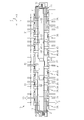
- FIG. 1 is a perspective view of the battery wiring module of the embodiment.
- FIG. 2 is a plan view showing a state in which the first cover and the second cover are removed in the battery wiring module of the same embodiment.
- FIG. 3 is an enlarged perspective view showing a part of the battery wiring module of the same form in an enlarged manner.
- FIG. 4 is an enlarged perspective view showing a part of the battery wiring module of the same form in an enlarged manner.
- FIG. 5 is a perspective view for explaining the operation of the battery wiring module of the same embodiment.
- FIG. 6 is a perspective view for explaining the operation of the battery wiring module of the same embodiment.
- the battery wiring module of the present disclosure is [1] A battery wiring module to be assembled to a secondary battery, comprising: an electric wire electrically connected to the secondary battery and a case for accommodating the electric wire, through which the electric wire is passed.
- a first case body having a groove-shaped first electric wire insertion portion, a second case main body having a groove-shaped second electric wire insertion portion through which the electric wire is passed, and a first case covering the opening of the first electric wire insertion portion. It has one cover and a second cover that covers the opening of the second electric wire insertion portion, and the first electric wire insertion portion and the second electric wire insertion portion are arranged side by side along the length direction of the electric wire.
- the opening of the first electric wire insertion portion and the opening of the second electric wire insertion portion are opened in the same direction as each other, and in the case, the first cover and the second cover are in the opening direction of both openings. Has overlapping portions that overlap each other.
- the first cover and the second cover are covered by the overlapping portion. It is possible to prevent a gap from being created between the two. Therefore, it is possible to prevent the electric wire from being exposed from between the first cover and the second cover. Further, by preventing a gap between the first cover and the second cover due to the overlapping portion, it is possible to prevent the electric wire from jumping out from the gap between the first cover and the second cover. It will be possible.
- the first cover has an extension portion extending to a position covering the opening of the second electric wire insertion portion to form the overlapping portion.
- the extension portion of the first cover makes it possible to form an overlapping portion in which the first cover and the second cover overlap each other.
- the extension portion has a locking portion that is locked to the second case main body in a direction along the opening direction of both openings.
- the extension portion of the first cover is lifted, that is, the extension portion of the first cover is separated from the second wire insertion portion in the opening direction by locking the locking portion to the second case body. It becomes possible to suppress it.
- the locking portion is provided at the tip of the extension portion.
- the extension portion of the first cover is lifted, that is, the extension portion of the first cover is separated from the second wire insertion portion in the opening direction by locking the locking portion to the second case body. , It becomes possible to further suppress.
- the locking portion is configured to be relatively movable in the direction along the length direction of the electric wire with respect to the second case main body.
- the extension portion of the first cover can be locked to the second case body, but the second case body can be relatively moved according to the thermal expansion of the secondary battery. ..
- the portion of the second cover in the overlapping portion is located inside the second electric wire insertion portion.
- the portion of the second cover in the overlapping portion of the first cover and the second cover is located inside the second electric wire insertion portion, the case is large in the opening direction of the second electric wire insertion portion. It is possible to form an overlapping portion between the first cover and the second cover without making the cover.
- the battery wiring module 10 of the present embodiment is assembled to a secondary battery BT mounted on, for example, an electric vehicle or a hybrid vehicle.
- the secondary battery BT supplies electric power to a traveling motor of a vehicle (not shown). Further, the secondary battery BT receives electric power from the traveling motor and the power generation motor according to the charging state and the operating state of the vehicle.
- the secondary battery BT includes a plurality of battery cells C.
- the secondary battery BT has, for example, a substantially rectangular parallelepiped shape by arranging a plurality of battery cells C side by side in one direction.
- the battery wiring module 10 is mounted on one side of the secondary battery BT.
- the surface of the secondary battery BT on which the battery wiring module 10 is mounted is the upper surface, and the battery wiring module 10 side is upward with respect to the secondary battery BT.
- the X-axis in the XYZ axes orthogonal to each other in the drawing represents the longitudinal direction X of the case 12 of the battery wiring module 10
- the Y-axis represents the width direction Y of the case 12
- the Z-axis represents the height direction of the case 12. Represents Z.
- Each battery cell C is arranged side by side along the longitudinal direction X of the battery wiring module 10.
- the battery wiring module 10 includes a plurality of electric wires 11 electrically connected to the secondary battery BT, and a case 12 for accommodating the electric wires 11. In FIG. 1, the electric wire 11 is not shown.
- the battery wiring module 10 of the present embodiment includes, for example, a plurality of bus bars 13 supported by the case 12.
- a plurality of bus bars 13 are arranged side by side along the longitudinal direction X of the case 12, for example, on both sides of the width direction Y of the case 12.
- Each bus bar 13 is connected to a positive electrode terminal and a negative electrode terminal (not shown) provided on the upper surface of each battery cell C.
- each bus bar 13 is electrically connected to the corresponding electric wire 11.
- Each electric wire 11 is inserted through the inside of the case 12 along the longitudinal direction X. A part of the plurality of electric wires 11 is led out of the case 12 from the first electric wire lead-out portion 14 provided at one end of the case 12 in the longitudinal direction X, and the remaining plurality of electric wires 11 are the lengths of the case 12. It is led out of the case 12 from the second electric wire lead-out portion 15 provided at the other end of the direction X.
- the case 12 has a first cover main body 21 and a second case main body 22 arranged in the longitudinal direction X of the case 12, and a first cover corresponding to the first case main body 21 and the second case main body 22, respectively. 23 and a second cover 24 are provided.
- the first case main body 21 and the second case main body 22 are separate from each other. Further, the first cover 23 and the second cover 24 are separate from each other.
- the first case main body 21, the second case main body 22, the first cover 23, and the second cover 24 are made of, for example, synthetic resin.
- the case 12 of this embodiment includes a pair of first case main bodies 21.
- the second case main body 22 is provided between the pair of first case main bodies 21.
- the pair of the first case main body 21 and the second case main body 22 are arranged side by side in the longitudinal direction X of the case 12.
- the first case main body 21 has a first electric wire lead-out unit 14, and the other first case main body 21 has a second electric wire lead-out unit 15.
- each first case main body 21 has a groove-shaped first electric wire insertion portion 31 through which the electric wire 11 is passed.
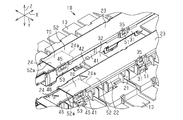
- FIG. 2 is a plan view of the battery wiring module 10 with the first cover 23 and the second cover 24 removed.
- the first electric wire insertion portion 31 extends along the longitudinal direction X of the case 12. Further, the first case main body 21 of the present embodiment has, for example, two first electric wire insertion portions 31 arranged in the width direction Y of the case 12. The two first electric wire insertion portions 31 are connected to each other by the first connecting portion 32.
- Each first electric wire insertion portion 31 includes a first bottom wall portion 33, a pair of first side wall portions 34 extending upward from the first bottom wall portion 33, and a plurality of first side wall portions 34. It has a first locked portion 35.
- the pair of first side wall portions 34 face each other in the width direction Y.
- the first electric wire insertion portion 31 is formed in a groove shape by the first bottom wall portion 33 and each first side wall portion 34.
- An electric wire 11 is inserted between the first side wall portions 34.
- the plurality of first locked portions 35 are provided so as to project from the outer surface of each first side wall portion 34.
- the first electric wire insertion portion 31 has an opening 36 that opens in a direction orthogonal to the insertion direction of the electric wire 11 on the open side of each first side wall portion 34, that is, on the upper end side of each first side wall portion 34. doing. That is, the opening 36 of the first electric wire insertion portion 31 of the present embodiment is open upward.
- the second case main body 22 has a groove-shaped second electric wire insertion portion 41 through which the electric wire 11 is passed.
- the second electric wire insertion portion 41 extends along the longitudinal direction X of the case 12.
- the first case main body 21 of the present embodiment has, for example, two second electric wire insertion portions 41 arranged in the width direction Y of the case 12. The two second electric wire insertion portions 41 are connected to each other by the second connecting portion 42.
- Each second electric wire insertion portion 41 is provided in a second bottom wall portion 43, a pair of second side wall portions 44 extending upward from the second bottom wall portion 43, and a second side wall portion 44. It has a locked portion 45 and.
- the pair of second side wall portions 44 face each other in the width direction Y.
- the second electric wire insertion portion 41 has a groove shape by the second bottom wall portion 43 and each second side wall portion 44.
- An electric wire 11 is inserted between the second side wall portions 44.
- the plurality of second locked portions 45 are provided so as to project from the outer surface of each second side wall portion 44.
- the second electric wire insertion portion 41 has an opening 46 that opens in a direction orthogonal to the insertion direction of the electric wire 11 on the open side of each second side wall portion 44, that is, on the upper end side of each second side wall portion 44. doing. That is, the opening 46 of the second electric wire insertion portion 41 of the present embodiment is open upward.
- the first electric wire insertion portion 31 of each first case main body 21 and the second electric wire insertion portion 41 of the second case main body 22 are arranged side by side along the longitudinal direction X of the case 12. Further, the opening 36 of the first electric wire insertion portion 31 and the opening 46 of the second electric wire insertion portion 41 are open in the same direction with each other.
- first cover 23 As shown in FIGS. 1 and 3, four first covers 23 of the present embodiment are provided corresponding to two first electric wire insertion portions 31 in the two first case main bodies 21.
- the first cover 23 is attached to the first case main body 21 so as to cover the opening 36 of the first electric wire insertion portion 31.
- the first cover 23 has a first locking portion 51 that is locked to the first locked portion 35 of the first electric wire insertion portion 31.
- a plurality of first locking portions 51 are provided corresponding to a plurality of first locked portions 35 of the first electric wire insertion portion 31.
- the first locking portion 51 is locked to the first locked portion 35 in the direction along the opening direction of the opening 36 of the first electric wire insertion portion 31, that is, in the height direction Z.
- the first cover 23 is attached to the first electric wire insertion portion 31.
- the first locking portion 51 is provided on both sides of the first cover 23 in the width direction Y.
- the first cover 23 has an extension portion 52 extending along the longitudinal direction X to a position covering the opening 46 of the second electric wire insertion portion 41.
- the extension portion 52 is located above the second electric wire insertion portion 41, that is, outside the second electric wire insertion portion 41, and covers the upper side of the opening 46 of the second electric wire insertion portion 41.
- the extension portion 52 has a second locking portion 53 that is locked to the second case main body 22 side.
- the second locking portion 53 is provided at the tip end portion 52a of the extension portion 52 in the longitudinal direction X.
- the second locking portion 53 is locked to the second locked portion 45, which is a part of the plurality of second locked portions 45.
- the second locking portion 53 is locked to the second locked portion 45 in the direction along the opening direction of the opening 46 of the second electric wire insertion portion 41, that is, in the height direction Z.
- the second locking portion 53 is provided on both sides of the extension portion 52 in the width direction Y.
- the second locking portion 53 is movable relative to the second locked portion 45 of the second electric wire insertion portion 41 in the direction along the length direction of the electric wire 11, that is, in the longitudinal direction X of the case 12. It is configured. Specifically, in the longitudinal direction X of the case 12, a gap is set between the second locking portion 53 and the second locked portion 45.
- two second covers 24 of the present embodiment are provided corresponding to the two second electric wire insertion portions 41 in the second case main body 22.
- the second cover 24 is attached to the second case main body 22 so as to cover the opening 46 of the second electric wire insertion portion 41.
- the second cover 24 has a third locking portion 61 that is locked to the second locked portion 45 of the second electric wire insertion portion 41.
- the third locking portion 61 is locked to the second locked portion 45 in the direction along the opening direction of the opening 46 of the second electric wire insertion portion 41, that is, in the height direction Z.
- the third locking portion 61 is provided on both sides of the second cover 24 in the width direction Y.
- the ends 24a on both sides of the second cover 24 in the longitudinal direction X are located below the extension portion 52 of the first cover 23. Further, both end portions 24a of the second cover 24 are located between the pair of second side wall portions 44. That is, both end portions 24a of the second cover 24 are located inside the second electric wire insertion portion 41.
- Both end portions 24a of the second cover 24 overlap the extension portion 52 of the first cover 23 in the direction along the opening direction of the opening 46 of the second electric wire insertion portion 41, that is, in the height direction Z.
- the overlapping portion 70 in which the second cover 24 and the extension portion 52 of the first cover 23 overlap each other in the height direction Z is configured.
- the second cover 24 and the extension portion 52 of the first cover 23 are in contact with each other in the height direction Z or face each other through a gap.
- the second cover 24 and the extension portion 52 of the first cover 23 are brought into contact with each other in the overlapping portion 70, it is possible to secure a large wire accommodating space of the second wire insertion portion 41.
- the overlapping portion 70 when the second cover 24 and the extension portion 52 of the first cover 23 are separated from each other, wear due to rubbing between the second cover 24 and the extension portion 52 of the first cover 23 is suppressed. It becomes possible to do.
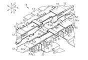
- FIG. 5 is a perspective view showing the state of the overlapping portion 70 when the secondary battery BT contracts in the longitudinal direction X of the case 12
- FIG. 6 is a perspective view showing the state of the overlapping portion 70 when the secondary battery BT expands in the longitudinal direction X of the case 12. It is a perspective view which shows the state of the overlap part 70 at the time. As shown in FIG. 6, even when the secondary battery BT is expanded, the overlapped portion 70 maintains a state in which the extension portion 52 of the first cover 23 and the second cover 24 overlap.
- the second locking portion 53 is configured to be movable relative to the second locked portion 45 of the second wire insertion portion 41 in the longitudinal direction X of the case 12.
- the first case main body 21 and the second case main body 22 can be configured to move relatively in the longitudinal direction X according to the contraction and expansion of the secondary battery BT in the longitudinal direction X. ing.
- the case 12 has an overlapping portion 70 in which the first cover 23 and the second cover 24 overlap each other in the opening directions of the openings 36 and 46 of the first and second electric wire insertion portions 31 and 41. According to this configuration, even if the distance between the first case main body 21 and the second case main body 22 along the length direction of the electric wire 11 becomes wide due to thermal expansion of the secondary battery BT or the like, the overlapping portion 70 makes the first case. It is possible to prevent a gap from being created between the cover 23 and the second cover 24. Therefore, it is possible to prevent the electric wire 11 from being exposed between the first cover 23 and the second cover 24. Further, by preventing the overlapping portion 70 from forming a gap between the first cover 23 and the second cover 24, the electric wire 11 protrudes to the outside from the gap between the first cover 23 and the second cover 24. It is possible to prevent this.
- the first cover 23 has an extension portion 52 extending to a position covering the opening 46 of the second electric wire insertion portion 41 to form an overlapping portion 70. According to this configuration, the extension portion 52 of the first cover 23 can form an overlapping portion 70 in which the first cover 23 and the second cover 24 overlap each other.
- the extension portion 52 of the first cover 23 has a second engagement with respect to the second case main body 22 in the height direction Z of the case 12, that is, in the direction along the opening direction of the openings 36 and 46. It has a stop 53. According to this configuration, the extension portion 52 of the first cover 23 is lifted, that is, the extension portion 52 of the first cover 23 is separated from the second electric wire insertion portion 41 in the opening direction by the second locking portion 53. 2 It can be suppressed by locking to the case body 22.
- the second locking portion 53 is provided at the tip end portion 52a of the extension portion 52. According to this configuration, the floating of the extension portion 52 of the first cover 23 can be further suppressed by locking the second locking portion 53 to the second case main body 22.
- the second locking portion 53 is configured to be relatively movable in the direction along the length direction of the electric wire 11 with respect to the second case main body 22. According to this configuration, the extension portion 52 of the first cover 23 is locked to the second case main body 22, but the second case main body 22 is subjected to thermal expansion in the longitudinal direction X of the secondary battery BT. It can be moved relatively.
- the portion of the second cover 24 in the overlapping portion 70 that is, the end portion 24a of the second case main body 22 in the longitudinal direction X is located inside the second electric wire insertion portion 41. According to this configuration, it is possible to form the overlapping portion 70 of the first cover 23 and the second cover 24 without increasing the size of the case 12 in the opening direction of the second electric wire insertion portion 41.
- the number of the first case main body 21 and the number of the first cover 23 changed accordingly are not limited to the above-described embodiment, and are appropriately determined according to the size of the secondary battery BT in the longitudinal direction X and the like. You may change it.
- the number of the first case main body 21 and the number of the first cover 23 may be one each.
- the end portion 24a of the second cover 24 constituting the overlapping portion 70 may be changed to a configuration located outside above the second electric wire insertion portion 41.
- the overlapping portion 70 may be changed to a configuration in which the extension portion 52 of the first cover 23 is located below the end portion 24a of the second cover 24.
- the second locking portion 53 may be provided at a portion other than the tip portion 52a of the extension portion 52 of the second cover 24.
- the first locking portion 51 of the first cover 23 is directed with respect to the first locked portion 35 of the first case main body 21 along the length direction of the electric wire 11, that is, the case. It may be configured to be relatively movable in the longitudinal direction X of 12.
- the first cover 23 located on the upper side has the extension portion 52, but in addition to this, for example, the first of the above embodiments. 1
- the extension portion 52 may be omitted from the cover 23.
- the second cover 24 located below the first cover 23 has an extension portion extending in the longitudinal direction X to the first electric wire insertion portion 31 of the first case main body 21, and the second cover 24 is the same.
- the extension portion may be configured to overlap the first cover 23 in the height direction Z.
- the overlapping portion 70 is configured in the region of the second electric wire insertion portion 41 in the longitudinal direction X of the case 12, but is not limited to this, for example, the first case main body in the longitudinal direction X of the case 12.
- the overlapping portion 70 may be formed in the area between the 21 and the second case main body 22. Further, for example, the overlapping portion 70 may be formed in the region of the first electric wire insertion portion 31 in the longitudinal direction X of the case 12.
- both openings 36 and 46 of the first electric wire insertion portion 31 and the second electric wire insertion portion 41 are opened in the same direction with each other, and their opening directions are set above the height direction Z, but both openings.
- the opening direction of the openings 36 and 46 may be a direction other than the upper direction, and for example, the opening direction of both openings 36 and 46 may be outside the width direction Y.
- the first cover 23 may be a separate body from the first case main body 21, or may be integrally molded with the first case main body 21.
- the second cover 24 may be a separate body from the second case main body 22, or may be integrally molded with the second case main body 22.
- the application is applied to the first electric wire insertion portion 31 and the second electric wire insertion portion 41 in which the electric wire 11 is inserted in the longitudinal direction X of the case 12 along the parallel direction of the battery cells C, but other than this.
- it may be applied to the first electric wire insertion portion and the second electric wire insertion portion through which the electric wire 11 is inserted along the width direction Y of the case 12.
Landscapes
- Chemical & Material Sciences (AREA)
- Chemical Kinetics & Catalysis (AREA)
- Electrochemistry (AREA)
- General Chemical & Material Sciences (AREA)
- Battery Mounting, Suspending (AREA)
- Connection Of Batteries Or Terminals (AREA)
Priority Applications (2)
| Application Number | Priority Date | Filing Date | Title |
|---|---|---|---|
| US17/924,077 US20230223640A1 (en) | 2020-05-25 | 2021-05-18 | Battery wiring module |
| CN202180033661.2A CN115606051A (zh) | 2020-05-25 | 2021-05-18 | 电池布线模块 |
Applications Claiming Priority (2)
| Application Number | Priority Date | Filing Date | Title |
|---|---|---|---|
| JP2020-090489 | 2020-05-25 | ||
| JP2020090489A JP7505265B2 (ja) | 2020-05-25 | 2020-05-25 | 電池配線モジュール |
Publications (1)
| Publication Number | Publication Date |
|---|---|
| WO2021241322A1 true WO2021241322A1 (ja) | 2021-12-02 |
Family
ID=78745106
Family Applications (1)
| Application Number | Title | Priority Date | Filing Date |
|---|---|---|---|
| PCT/JP2021/018755 Ceased WO2021241322A1 (ja) | 2020-05-25 | 2021-05-18 | 電池配線モジュール |
Country Status (4)
| Country | Link |
|---|---|
| US (1) | US20230223640A1 (enExample) |
| JP (1) | JP7505265B2 (enExample) |
| CN (1) | CN115606051A (enExample) |
| WO (1) | WO2021241322A1 (enExample) |
Citations (3)
| Publication number | Priority date | Publication date | Assignee | Title |
|---|---|---|---|---|
| JP2013037878A (ja) * | 2011-08-08 | 2013-02-21 | Auto Network Gijutsu Kenkyusho:Kk | 電池配線モジュールのカバー、及び電池配線モジュール |
| JP2018101545A (ja) * | 2016-12-20 | 2018-06-28 | 矢崎総業株式会社 | 収容部材の連結構造及び収納ケース |
| JP2018181562A (ja) * | 2017-04-11 | 2018-11-15 | 住友電装株式会社 | 電池配線モジュール |
Family Cites Families (8)
| Publication number | Priority date | Publication date | Assignee | Title |
|---|---|---|---|---|
| JP5550291B2 (ja) * | 2009-09-17 | 2014-07-16 | 矢崎総業株式会社 | 電線配索体、バスバモジュール、及び、電源装置 |
| JP5550290B2 (ja) * | 2009-09-17 | 2014-07-16 | 矢崎総業株式会社 | 電線配索体、バスバモジュール、及び、電源装置 |
| JP5613074B2 (ja) * | 2011-02-09 | 2014-10-22 | 矢崎総業株式会社 | バスバモジュール及び電源装置 |
| JP5772524B2 (ja) * | 2011-11-11 | 2015-09-02 | 株式会社オートネットワーク技術研究所 | 電池配線モジュール |
| JP5779513B2 (ja) * | 2012-02-02 | 2015-09-16 | 株式会社オートネットワーク技術研究所 | 電池配線モジュール |
| JP6372417B2 (ja) * | 2015-04-14 | 2018-08-15 | 住友電装株式会社 | 電池配線モジュール |
| JP6633989B2 (ja) * | 2016-07-29 | 2020-01-22 | 矢崎総業株式会社 | 電池パック |
| CN210349932U (zh) * | 2019-09-23 | 2020-04-17 | 永康市光逸科技有限公司 | 一种电池包 |
-
2020
- 2020-05-25 JP JP2020090489A patent/JP7505265B2/ja active Active
-
2021
- 2021-05-18 US US17/924,077 patent/US20230223640A1/en active Pending
- 2021-05-18 WO PCT/JP2021/018755 patent/WO2021241322A1/ja not_active Ceased
- 2021-05-18 CN CN202180033661.2A patent/CN115606051A/zh active Pending
Patent Citations (3)
| Publication number | Priority date | Publication date | Assignee | Title |
|---|---|---|---|---|
| JP2013037878A (ja) * | 2011-08-08 | 2013-02-21 | Auto Network Gijutsu Kenkyusho:Kk | 電池配線モジュールのカバー、及び電池配線モジュール |
| JP2018101545A (ja) * | 2016-12-20 | 2018-06-28 | 矢崎総業株式会社 | 収容部材の連結構造及び収納ケース |
| JP2018181562A (ja) * | 2017-04-11 | 2018-11-15 | 住友電装株式会社 | 電池配線モジュール |
Also Published As
| Publication number | Publication date |
|---|---|
| JP7505265B2 (ja) | 2024-06-25 |
| JP2021185563A (ja) | 2021-12-09 |
| CN115606051A (zh) | 2023-01-13 |
| US20230223640A1 (en) | 2023-07-13 |
Similar Documents
| Publication | Publication Date | Title |
|---|---|---|
| CN108695481B (zh) | 电池布线模块 | |
| CN110875457B (zh) | 电池布线模块 | |
| WO2021241322A1 (ja) | 電池配線モジュール | |
| JP7400625B2 (ja) | 電池配線モジュール | |
| JP7687470B2 (ja) | 電池配線モジュール | |
| JP7028106B2 (ja) | 電池配線モジュール | |
| WO2021131861A1 (ja) | 電池配線モジュール | |
| JP7544102B2 (ja) | 電池配線モジュール | |
| JP7727674B2 (ja) | プロテクタおよびワイヤハーネス | |
| JP7409251B2 (ja) | コネクタ | |
| JP7001022B2 (ja) | 電池配線モジュール | |
| JP2024150919A (ja) | プロテクタおよびワイヤハーネス | |
| JP2021111484A (ja) | 電池配線モジュール | |
| JP2021175268A (ja) | 電気接続箱 | |
| JP2012085483A (ja) | ワイヤハーネス |
Legal Events
| Date | Code | Title | Description |
|---|---|---|---|
| 121 | Ep: the epo has been informed by wipo that ep was designated in this application |
Ref document number: 21814074 Country of ref document: EP Kind code of ref document: A1 |
|
| NENP | Non-entry into the national phase |
Ref country code: DE |
|
| 122 | Ep: pct application non-entry in european phase |
Ref document number: 21814074 Country of ref document: EP Kind code of ref document: A1 |