WO2021241322A1 - Battery wiring module - Google Patents
Battery wiring module Download PDFInfo
- Publication number
- WO2021241322A1 WO2021241322A1 PCT/JP2021/018755 JP2021018755W WO2021241322A1 WO 2021241322 A1 WO2021241322 A1 WO 2021241322A1 JP 2021018755 W JP2021018755 W JP 2021018755W WO 2021241322 A1 WO2021241322 A1 WO 2021241322A1
- Authority
- WO
- WIPO (PCT)
- Prior art keywords
- electric wire
- cover
- wire insertion
- case
- opening
- Prior art date
Links
Images


Classifications
-
- H—ELECTRICITY
- H01—ELECTRIC ELEMENTS
- H01M—PROCESSES OR MEANS, e.g. BATTERIES, FOR THE DIRECT CONVERSION OF CHEMICAL ENERGY INTO ELECTRICAL ENERGY
- H01M50/00—Constructional details or processes of manufacture of the non-active parts of electrochemical cells other than fuel cells, e.g. hybrid cells
- H01M50/20—Mountings; Secondary casings or frames; Racks, modules or packs; Suspension devices; Shock absorbers; Transport or carrying devices; Holders
- H01M50/298—Mountings; Secondary casings or frames; Racks, modules or packs; Suspension devices; Shock absorbers; Transport or carrying devices; Holders characterised by the wiring of battery packs
-
- H—ELECTRICITY
- H01—ELECTRIC ELEMENTS
- H01M—PROCESSES OR MEANS, e.g. BATTERIES, FOR THE DIRECT CONVERSION OF CHEMICAL ENERGY INTO ELECTRICAL ENERGY
- H01M50/00—Constructional details or processes of manufacture of the non-active parts of electrochemical cells other than fuel cells, e.g. hybrid cells
- H01M50/50—Current conducting connections for cells or batteries
- H01M50/502—Interconnectors for connecting terminals of adjacent batteries; Interconnectors for connecting cells outside a battery casing
- H01M50/503—Interconnectors for connecting terminals of adjacent batteries; Interconnectors for connecting cells outside a battery casing characterised by the shape of the interconnectors
-
- H—ELECTRICITY
- H01—ELECTRIC ELEMENTS
- H01M—PROCESSES OR MEANS, e.g. BATTERIES, FOR THE DIRECT CONVERSION OF CHEMICAL ENERGY INTO ELECTRICAL ENERGY
- H01M50/00—Constructional details or processes of manufacture of the non-active parts of electrochemical cells other than fuel cells, e.g. hybrid cells
- H01M50/50—Current conducting connections for cells or batteries
- H01M50/531—Electrode connections inside a battery casing
-
- H—ELECTRICITY
- H01—ELECTRIC ELEMENTS
- H01M—PROCESSES OR MEANS, e.g. BATTERIES, FOR THE DIRECT CONVERSION OF CHEMICAL ENERGY INTO ELECTRICAL ENERGY
- H01M2220/00—Batteries for particular applications
- H01M2220/20—Batteries in motive systems, e.g. vehicle, ship, plane
-
- H—ELECTRICITY
- H01—ELECTRIC ELEMENTS
- H01M—PROCESSES OR MEANS, e.g. BATTERIES, FOR THE DIRECT CONVERSION OF CHEMICAL ENERGY INTO ELECTRICAL ENERGY
- H01M50/00—Constructional details or processes of manufacture of the non-active parts of electrochemical cells other than fuel cells, e.g. hybrid cells
- H01M50/50—Current conducting connections for cells or batteries
- H01M50/502—Interconnectors for connecting terminals of adjacent batteries; Interconnectors for connecting cells outside a battery casing
- H01M50/507—Interconnectors for connecting terminals of adjacent batteries; Interconnectors for connecting cells outside a battery casing comprising an arrangement of two or more busbars within a container structure, e.g. busbar modules
-
- Y—GENERAL TAGGING OF NEW TECHNOLOGICAL DEVELOPMENTS; GENERAL TAGGING OF CROSS-SECTIONAL TECHNOLOGIES SPANNING OVER SEVERAL SECTIONS OF THE IPC; TECHNICAL SUBJECTS COVERED BY FORMER USPC CROSS-REFERENCE ART COLLECTIONS [XRACs] AND DIGESTS
- Y02—TECHNOLOGIES OR APPLICATIONS FOR MITIGATION OR ADAPTATION AGAINST CLIMATE CHANGE
- Y02E—REDUCTION OF GREENHOUSE GAS [GHG] EMISSIONS, RELATED TO ENERGY GENERATION, TRANSMISSION OR DISTRIBUTION
- Y02E60/00—Enabling technologies; Technologies with a potential or indirect contribution to GHG emissions mitigation
- Y02E60/10—Energy storage using batteries
Definitions
- This disclosure relates to a battery wiring module.
- a battery wiring module is mounted on a high-voltage secondary battery mounted as a power source for driving a vehicle.
- the battery wiring module of Patent Document 1 includes an electric wire electrically connected to a secondary battery and a case for accommodating the electric wire.
- the case of the battery wiring module has a plurality of case bodies arranged along the length direction of the electric wire, and a plurality of covers corresponding to each of the plurality of case bodies.
- Each case body has a groove-shaped wire insertion portion through which an electric wire is passed, and each cover covers the wire insertion portion of the corresponding case body. The cover protects the wire passing through the wire insertion part of the case body.
- each case body and each cover follow the thermal expansion of the secondary battery in the length direction of the electric wire. Since it moves along the line, the connection between the secondary battery and the battery wiring module is highly reliable.
- the battery wiring module of the present disclosure is a battery wiring module to be assembled to a secondary battery, and includes an electric wire electrically connected to the secondary battery and a case for accommodating the electric wire.
- a first case main body having a groove-shaped first electric wire insertion portion through which the electric wire is passed, a second case main body having a groove-shaped second electric wire insertion portion through which the electric wire is passed, and the first electric wire insertion portion. It has a first cover that covers the opening of the second electric wire and a second cover that covers the opening of the second electric wire insertion portion, and the first electric wire insertion portion and the second electric wire insertion portion are in the length direction of the electric wire.
- the opening of the first electric wire insertion portion and the opening of the second electric wire insertion portion are arranged side by side along the same direction, and in the case, the first cover and the second cover are the same. It has overlapping portions that overlap each other in the opening direction of both openings.
- a battery wiring module capable of suppressing the exposure of electric wires from between the covers covering the electric wire insertion portions of the case body.
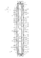
- FIG. 1 is a perspective view of the battery wiring module of the embodiment.
- FIG. 2 is a plan view showing a state in which the first cover and the second cover are removed in the battery wiring module of the same embodiment.
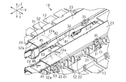
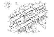
- FIG. 3 is an enlarged perspective view showing a part of the battery wiring module of the same form in an enlarged manner.
- FIG. 4 is an enlarged perspective view showing a part of the battery wiring module of the same form in an enlarged manner.
- FIG. 5 is a perspective view for explaining the operation of the battery wiring module of the same embodiment.
- FIG. 6 is a perspective view for explaining the operation of the battery wiring module of the same embodiment.
- the battery wiring module of the present disclosure is [1] A battery wiring module to be assembled to a secondary battery, comprising: an electric wire electrically connected to the secondary battery and a case for accommodating the electric wire, through which the electric wire is passed.
- a first case body having a groove-shaped first electric wire insertion portion, a second case main body having a groove-shaped second electric wire insertion portion through which the electric wire is passed, and a first case covering the opening of the first electric wire insertion portion. It has one cover and a second cover that covers the opening of the second electric wire insertion portion, and the first electric wire insertion portion and the second electric wire insertion portion are arranged side by side along the length direction of the electric wire.
- the opening of the first electric wire insertion portion and the opening of the second electric wire insertion portion are opened in the same direction as each other, and in the case, the first cover and the second cover are in the opening direction of both openings. Has overlapping portions that overlap each other.
- the first cover and the second cover are covered by the overlapping portion. It is possible to prevent a gap from being created between the two. Therefore, it is possible to prevent the electric wire from being exposed from between the first cover and the second cover. Further, by preventing a gap between the first cover and the second cover due to the overlapping portion, it is possible to prevent the electric wire from jumping out from the gap between the first cover and the second cover. It will be possible.
- the first cover has an extension portion extending to a position covering the opening of the second electric wire insertion portion to form the overlapping portion.
- the extension portion of the first cover makes it possible to form an overlapping portion in which the first cover and the second cover overlap each other.
- the extension portion has a locking portion that is locked to the second case main body in a direction along the opening direction of both openings.
- the extension portion of the first cover is lifted, that is, the extension portion of the first cover is separated from the second wire insertion portion in the opening direction by locking the locking portion to the second case body. It becomes possible to suppress it.
- the locking portion is provided at the tip of the extension portion.
- the extension portion of the first cover is lifted, that is, the extension portion of the first cover is separated from the second wire insertion portion in the opening direction by locking the locking portion to the second case body. , It becomes possible to further suppress.
- the locking portion is configured to be relatively movable in the direction along the length direction of the electric wire with respect to the second case main body.
- the extension portion of the first cover can be locked to the second case body, but the second case body can be relatively moved according to the thermal expansion of the secondary battery. ..
- the portion of the second cover in the overlapping portion is located inside the second electric wire insertion portion.
- the portion of the second cover in the overlapping portion of the first cover and the second cover is located inside the second electric wire insertion portion, the case is large in the opening direction of the second electric wire insertion portion. It is possible to form an overlapping portion between the first cover and the second cover without making the cover.
- the battery wiring module 10 of the present embodiment is assembled to a secondary battery BT mounted on, for example, an electric vehicle or a hybrid vehicle.
- the secondary battery BT supplies electric power to a traveling motor of a vehicle (not shown). Further, the secondary battery BT receives electric power from the traveling motor and the power generation motor according to the charging state and the operating state of the vehicle.
- the secondary battery BT includes a plurality of battery cells C.
- the secondary battery BT has, for example, a substantially rectangular parallelepiped shape by arranging a plurality of battery cells C side by side in one direction.
- the battery wiring module 10 is mounted on one side of the secondary battery BT.
- the surface of the secondary battery BT on which the battery wiring module 10 is mounted is the upper surface, and the battery wiring module 10 side is upward with respect to the secondary battery BT.
- the X-axis in the XYZ axes orthogonal to each other in the drawing represents the longitudinal direction X of the case 12 of the battery wiring module 10
- the Y-axis represents the width direction Y of the case 12
- the Z-axis represents the height direction of the case 12. Represents Z.
- Each battery cell C is arranged side by side along the longitudinal direction X of the battery wiring module 10.
- the battery wiring module 10 includes a plurality of electric wires 11 electrically connected to the secondary battery BT, and a case 12 for accommodating the electric wires 11. In FIG. 1, the electric wire 11 is not shown.
- the battery wiring module 10 of the present embodiment includes, for example, a plurality of bus bars 13 supported by the case 12.
- a plurality of bus bars 13 are arranged side by side along the longitudinal direction X of the case 12, for example, on both sides of the width direction Y of the case 12.
- Each bus bar 13 is connected to a positive electrode terminal and a negative electrode terminal (not shown) provided on the upper surface of each battery cell C.
- each bus bar 13 is electrically connected to the corresponding electric wire 11.
- Each electric wire 11 is inserted through the inside of the case 12 along the longitudinal direction X. A part of the plurality of electric wires 11 is led out of the case 12 from the first electric wire lead-out portion 14 provided at one end of the case 12 in the longitudinal direction X, and the remaining plurality of electric wires 11 are the lengths of the case 12. It is led out of the case 12 from the second electric wire lead-out portion 15 provided at the other end of the direction X.
- the case 12 has a first cover main body 21 and a second case main body 22 arranged in the longitudinal direction X of the case 12, and a first cover corresponding to the first case main body 21 and the second case main body 22, respectively. 23 and a second cover 24 are provided.
- the first case main body 21 and the second case main body 22 are separate from each other. Further, the first cover 23 and the second cover 24 are separate from each other.
- the first case main body 21, the second case main body 22, the first cover 23, and the second cover 24 are made of, for example, synthetic resin.
- the case 12 of this embodiment includes a pair of first case main bodies 21.
- the second case main body 22 is provided between the pair of first case main bodies 21.
- the pair of the first case main body 21 and the second case main body 22 are arranged side by side in the longitudinal direction X of the case 12.
- the first case main body 21 has a first electric wire lead-out unit 14, and the other first case main body 21 has a second electric wire lead-out unit 15.
- each first case main body 21 has a groove-shaped first electric wire insertion portion 31 through which the electric wire 11 is passed.
- FIG. 2 is a plan view of the battery wiring module 10 with the first cover 23 and the second cover 24 removed.
- the first electric wire insertion portion 31 extends along the longitudinal direction X of the case 12. Further, the first case main body 21 of the present embodiment has, for example, two first electric wire insertion portions 31 arranged in the width direction Y of the case 12. The two first electric wire insertion portions 31 are connected to each other by the first connecting portion 32.
- Each first electric wire insertion portion 31 includes a first bottom wall portion 33, a pair of first side wall portions 34 extending upward from the first bottom wall portion 33, and a plurality of first side wall portions 34. It has a first locked portion 35.
- the pair of first side wall portions 34 face each other in the width direction Y.
- the first electric wire insertion portion 31 is formed in a groove shape by the first bottom wall portion 33 and each first side wall portion 34.
- An electric wire 11 is inserted between the first side wall portions 34.
- the plurality of first locked portions 35 are provided so as to project from the outer surface of each first side wall portion 34.
- the first electric wire insertion portion 31 has an opening 36 that opens in a direction orthogonal to the insertion direction of the electric wire 11 on the open side of each first side wall portion 34, that is, on the upper end side of each first side wall portion 34. doing. That is, the opening 36 of the first electric wire insertion portion 31 of the present embodiment is open upward.
- the second case main body 22 has a groove-shaped second electric wire insertion portion 41 through which the electric wire 11 is passed.
- the second electric wire insertion portion 41 extends along the longitudinal direction X of the case 12.
- the first case main body 21 of the present embodiment has, for example, two second electric wire insertion portions 41 arranged in the width direction Y of the case 12. The two second electric wire insertion portions 41 are connected to each other by the second connecting portion 42.
- Each second electric wire insertion portion 41 is provided in a second bottom wall portion 43, a pair of second side wall portions 44 extending upward from the second bottom wall portion 43, and a second side wall portion 44. It has a locked portion 45 and.
- the pair of second side wall portions 44 face each other in the width direction Y.
- the second electric wire insertion portion 41 has a groove shape by the second bottom wall portion 43 and each second side wall portion 44.
- An electric wire 11 is inserted between the second side wall portions 44.
- the plurality of second locked portions 45 are provided so as to project from the outer surface of each second side wall portion 44.
- the second electric wire insertion portion 41 has an opening 46 that opens in a direction orthogonal to the insertion direction of the electric wire 11 on the open side of each second side wall portion 44, that is, on the upper end side of each second side wall portion 44. doing. That is, the opening 46 of the second electric wire insertion portion 41 of the present embodiment is open upward.
- the first electric wire insertion portion 31 of each first case main body 21 and the second electric wire insertion portion 41 of the second case main body 22 are arranged side by side along the longitudinal direction X of the case 12. Further, the opening 36 of the first electric wire insertion portion 31 and the opening 46 of the second electric wire insertion portion 41 are open in the same direction with each other.
- first cover 23 As shown in FIGS. 1 and 3, four first covers 23 of the present embodiment are provided corresponding to two first electric wire insertion portions 31 in the two first case main bodies 21.
- the first cover 23 is attached to the first case main body 21 so as to cover the opening 36 of the first electric wire insertion portion 31.
- the first cover 23 has a first locking portion 51 that is locked to the first locked portion 35 of the first electric wire insertion portion 31.
- a plurality of first locking portions 51 are provided corresponding to a plurality of first locked portions 35 of the first electric wire insertion portion 31.
- the first locking portion 51 is locked to the first locked portion 35 in the direction along the opening direction of the opening 36 of the first electric wire insertion portion 31, that is, in the height direction Z.
- the first cover 23 is attached to the first electric wire insertion portion 31.
- the first locking portion 51 is provided on both sides of the first cover 23 in the width direction Y.
- the first cover 23 has an extension portion 52 extending along the longitudinal direction X to a position covering the opening 46 of the second electric wire insertion portion 41.
- the extension portion 52 is located above the second electric wire insertion portion 41, that is, outside the second electric wire insertion portion 41, and covers the upper side of the opening 46 of the second electric wire insertion portion 41.
- the extension portion 52 has a second locking portion 53 that is locked to the second case main body 22 side.
- the second locking portion 53 is provided at the tip end portion 52a of the extension portion 52 in the longitudinal direction X.
- the second locking portion 53 is locked to the second locked portion 45, which is a part of the plurality of second locked portions 45.
- the second locking portion 53 is locked to the second locked portion 45 in the direction along the opening direction of the opening 46 of the second electric wire insertion portion 41, that is, in the height direction Z.
- the second locking portion 53 is provided on both sides of the extension portion 52 in the width direction Y.
- the second locking portion 53 is movable relative to the second locked portion 45 of the second electric wire insertion portion 41 in the direction along the length direction of the electric wire 11, that is, in the longitudinal direction X of the case 12. It is configured. Specifically, in the longitudinal direction X of the case 12, a gap is set between the second locking portion 53 and the second locked portion 45.
- two second covers 24 of the present embodiment are provided corresponding to the two second electric wire insertion portions 41 in the second case main body 22.
- the second cover 24 is attached to the second case main body 22 so as to cover the opening 46 of the second electric wire insertion portion 41.
- the second cover 24 has a third locking portion 61 that is locked to the second locked portion 45 of the second electric wire insertion portion 41.
- the third locking portion 61 is locked to the second locked portion 45 in the direction along the opening direction of the opening 46 of the second electric wire insertion portion 41, that is, in the height direction Z.
- the third locking portion 61 is provided on both sides of the second cover 24 in the width direction Y.
- the ends 24a on both sides of the second cover 24 in the longitudinal direction X are located below the extension portion 52 of the first cover 23. Further, both end portions 24a of the second cover 24 are located between the pair of second side wall portions 44. That is, both end portions 24a of the second cover 24 are located inside the second electric wire insertion portion 41.
- Both end portions 24a of the second cover 24 overlap the extension portion 52 of the first cover 23 in the direction along the opening direction of the opening 46 of the second electric wire insertion portion 41, that is, in the height direction Z.
- the overlapping portion 70 in which the second cover 24 and the extension portion 52 of the first cover 23 overlap each other in the height direction Z is configured.
- the second cover 24 and the extension portion 52 of the first cover 23 are in contact with each other in the height direction Z or face each other through a gap.
- the second cover 24 and the extension portion 52 of the first cover 23 are brought into contact with each other in the overlapping portion 70, it is possible to secure a large wire accommodating space of the second wire insertion portion 41.
- the overlapping portion 70 when the second cover 24 and the extension portion 52 of the first cover 23 are separated from each other, wear due to rubbing between the second cover 24 and the extension portion 52 of the first cover 23 is suppressed. It becomes possible to do.
- FIG. 5 is a perspective view showing the state of the overlapping portion 70 when the secondary battery BT contracts in the longitudinal direction X of the case 12
- FIG. 6 is a perspective view showing the state of the overlapping portion 70 when the secondary battery BT expands in the longitudinal direction X of the case 12. It is a perspective view which shows the state of the overlap part 70 at the time. As shown in FIG. 6, even when the secondary battery BT is expanded, the overlapped portion 70 maintains a state in which the extension portion 52 of the first cover 23 and the second cover 24 overlap.
- the second locking portion 53 is configured to be movable relative to the second locked portion 45 of the second wire insertion portion 41 in the longitudinal direction X of the case 12.
- the first case main body 21 and the second case main body 22 can be configured to move relatively in the longitudinal direction X according to the contraction and expansion of the secondary battery BT in the longitudinal direction X. ing.
- the case 12 has an overlapping portion 70 in which the first cover 23 and the second cover 24 overlap each other in the opening directions of the openings 36 and 46 of the first and second electric wire insertion portions 31 and 41. According to this configuration, even if the distance between the first case main body 21 and the second case main body 22 along the length direction of the electric wire 11 becomes wide due to thermal expansion of the secondary battery BT or the like, the overlapping portion 70 makes the first case. It is possible to prevent a gap from being created between the cover 23 and the second cover 24. Therefore, it is possible to prevent the electric wire 11 from being exposed between the first cover 23 and the second cover 24. Further, by preventing the overlapping portion 70 from forming a gap between the first cover 23 and the second cover 24, the electric wire 11 protrudes to the outside from the gap between the first cover 23 and the second cover 24. It is possible to prevent this.
- the first cover 23 has an extension portion 52 extending to a position covering the opening 46 of the second electric wire insertion portion 41 to form an overlapping portion 70. According to this configuration, the extension portion 52 of the first cover 23 can form an overlapping portion 70 in which the first cover 23 and the second cover 24 overlap each other.
- the extension portion 52 of the first cover 23 has a second engagement with respect to the second case main body 22 in the height direction Z of the case 12, that is, in the direction along the opening direction of the openings 36 and 46. It has a stop 53. According to this configuration, the extension portion 52 of the first cover 23 is lifted, that is, the extension portion 52 of the first cover 23 is separated from the second electric wire insertion portion 41 in the opening direction by the second locking portion 53. 2 It can be suppressed by locking to the case body 22.
- the second locking portion 53 is provided at the tip end portion 52a of the extension portion 52. According to this configuration, the floating of the extension portion 52 of the first cover 23 can be further suppressed by locking the second locking portion 53 to the second case main body 22.
- the second locking portion 53 is configured to be relatively movable in the direction along the length direction of the electric wire 11 with respect to the second case main body 22. According to this configuration, the extension portion 52 of the first cover 23 is locked to the second case main body 22, but the second case main body 22 is subjected to thermal expansion in the longitudinal direction X of the secondary battery BT. It can be moved relatively.
- the portion of the second cover 24 in the overlapping portion 70 that is, the end portion 24a of the second case main body 22 in the longitudinal direction X is located inside the second electric wire insertion portion 41. According to this configuration, it is possible to form the overlapping portion 70 of the first cover 23 and the second cover 24 without increasing the size of the case 12 in the opening direction of the second electric wire insertion portion 41.
- the number of the first case main body 21 and the number of the first cover 23 changed accordingly are not limited to the above-described embodiment, and are appropriately determined according to the size of the secondary battery BT in the longitudinal direction X and the like. You may change it.
- the number of the first case main body 21 and the number of the first cover 23 may be one each.
- the end portion 24a of the second cover 24 constituting the overlapping portion 70 may be changed to a configuration located outside above the second electric wire insertion portion 41.
- the overlapping portion 70 may be changed to a configuration in which the extension portion 52 of the first cover 23 is located below the end portion 24a of the second cover 24.
- the second locking portion 53 may be provided at a portion other than the tip portion 52a of the extension portion 52 of the second cover 24.
- the first locking portion 51 of the first cover 23 is directed with respect to the first locked portion 35 of the first case main body 21 along the length direction of the electric wire 11, that is, the case. It may be configured to be relatively movable in the longitudinal direction X of 12.
- the first cover 23 located on the upper side has the extension portion 52, but in addition to this, for example, the first of the above embodiments. 1
- the extension portion 52 may be omitted from the cover 23.
- the second cover 24 located below the first cover 23 has an extension portion extending in the longitudinal direction X to the first electric wire insertion portion 31 of the first case main body 21, and the second cover 24 is the same.
- the extension portion may be configured to overlap the first cover 23 in the height direction Z.
- the overlapping portion 70 is configured in the region of the second electric wire insertion portion 41 in the longitudinal direction X of the case 12, but is not limited to this, for example, the first case main body in the longitudinal direction X of the case 12.
- the overlapping portion 70 may be formed in the area between the 21 and the second case main body 22. Further, for example, the overlapping portion 70 may be formed in the region of the first electric wire insertion portion 31 in the longitudinal direction X of the case 12.
- both openings 36 and 46 of the first electric wire insertion portion 31 and the second electric wire insertion portion 41 are opened in the same direction with each other, and their opening directions are set above the height direction Z, but both openings.
- the opening direction of the openings 36 and 46 may be a direction other than the upper direction, and for example, the opening direction of both openings 36 and 46 may be outside the width direction Y.
- the first cover 23 may be a separate body from the first case main body 21, or may be integrally molded with the first case main body 21.
- the second cover 24 may be a separate body from the second case main body 22, or may be integrally molded with the second case main body 22.
- the application is applied to the first electric wire insertion portion 31 and the second electric wire insertion portion 41 in which the electric wire 11 is inserted in the longitudinal direction X of the case 12 along the parallel direction of the battery cells C, but other than this.
- it may be applied to the first electric wire insertion portion and the second electric wire insertion portion through which the electric wire 11 is inserted along the width direction Y of the case 12.
Landscapes
- Chemical & Material Sciences (AREA)
- Chemical Kinetics & Catalysis (AREA)
- Electrochemistry (AREA)
- General Chemical & Material Sciences (AREA)
- Battery Mounting, Suspending (AREA)
- Connection Of Batteries Or Terminals (AREA)
Abstract
The present disclosure addresses the problem of providing a battery wiring module that can suppress exposure of an electrical wire from between covers that cover wire insertion parts of case bodies. A case of this battery wiring module (10) has a first case body (21) that has a groove-shaped first wire insertion part (31), a second case body (22) that has a groove-shaped second wire insertion part (41), a first cover (23) that covers the opening of the first wire insertion part (31), and a second cover (24) that covers an opening (46) of the second wire insertion part (41). The first wire insertion part (31) and the second wire insertion part (41) are provided in parallel along the length direction of the electrical wire. The opening of the first wire insertion part (31) and the opening (46) of the second wire insertion part (41) open in the same direction as each other. The case has an overlapping part (70) in which the first cover (23) and the second cover (24) mutually overlap in the opening direction of the opening (46) of the first and second wire insertion parts (31, 41).
Description
本開示は、電池配線モジュールに関するものである。
This disclosure relates to a battery wiring module.
例えば特許文献1に開示されるように、電気自動車やハイブリッド自動車などの車両において、走行駆動用の電源として搭載される高電圧の二次電池には、電池配線モジュールが装着されている。特許文献1の電池配線モジュールは、二次電池に電気的に接続される電線と、その電線を収容するケースと、を備えている。電池配線モジュールのケースは、電線の長さ方向に沿って並ぶ複数のケース本体と、複数のケース本体の各々に対応する複数のカバーとを有している。各ケース本体は、電線が通される溝状の電線挿通部を有しており、各カバーはそれぞれ対応するケース本体の電線挿通部を覆っている。カバーは、ケース本体の電線挿通部を通る電線を保護する。このような構成によれば、例えば、二次電池が電線の長さ方向に沿って熱膨張したとき、各ケース本体及び各カバーが二次電池の熱膨張に追従して電線の長さ方向に沿って動くため、二次電池と電池配線モジュールとの間の接続信頼性が高いものとなる。
For example, as disclosed in Patent Document 1, in a vehicle such as an electric vehicle or a hybrid vehicle, a battery wiring module is mounted on a high-voltage secondary battery mounted as a power source for driving a vehicle. The battery wiring module of Patent Document 1 includes an electric wire electrically connected to a secondary battery and a case for accommodating the electric wire. The case of the battery wiring module has a plurality of case bodies arranged along the length direction of the electric wire, and a plurality of covers corresponding to each of the plurality of case bodies. Each case body has a groove-shaped wire insertion portion through which an electric wire is passed, and each cover covers the wire insertion portion of the corresponding case body. The cover protects the wire passing through the wire insertion part of the case body. According to such a configuration, for example, when the secondary battery thermally expands along the length direction of the electric wire, each case body and each cover follow the thermal expansion of the secondary battery in the length direction of the electric wire. Since it moves along the line, the connection between the secondary battery and the battery wiring module is highly reliable.
上記のような電池配線モジュールでは、二次電池の熱膨張などによって、電線の長さ方向に沿った方向におけるケース本体同士の間隔が広くなったとき、ケース本体と共に動くカバー同士の間隔も広くなってしまい、カバー同士の間の隙間から電線が露出するおそれがあった。
In the battery wiring module as described above, when the distance between the case bodies in the direction along the length direction of the electric wire becomes wide due to the thermal expansion of the secondary battery, the distance between the covers that move together with the case body also becomes wide. There was a risk that the wires would be exposed from the gaps between the covers.
そこで、ケース本体の電線挿通部を覆うカバー同士の間から電線が露出することを抑制可能とした電池配線モジュールを提供することを目的とする。
Therefore, it is an object of the present invention to provide a battery wiring module capable of suppressing the exposure of electric wires from between the covers covering the electric wire insertion portions of the case body.
本開示の電池配線モジュールは、二次電池に組み付けられる電池配線モジュールであって、前記二次電池に電気的に接続される電線と、前記電線を収容するケースと、を備え、前記ケースは、前記電線が通される溝状の第1電線挿通部を有する第1ケース本体と、前記電線が通される溝状の第2電線挿通部を有する第2ケース本体と、前記第1電線挿通部の開口を覆う第1カバーと、前記第2電線挿通部の開口を覆う第2カバーと、を有し、前記第1電線挿通部及び前記第2電線挿通部は、前記電線の長さ方向に沿って並設され、前記第1電線挿通部の前記開口及び前記第2電線挿通部の前記開口は、互いに同方向に開口し、前記ケースは、前記第1カバーと前記第2カバーとが前記両開口の開口方向において互いに重なる重なり部を有している。
The battery wiring module of the present disclosure is a battery wiring module to be assembled to a secondary battery, and includes an electric wire electrically connected to the secondary battery and a case for accommodating the electric wire. A first case main body having a groove-shaped first electric wire insertion portion through which the electric wire is passed, a second case main body having a groove-shaped second electric wire insertion portion through which the electric wire is passed, and the first electric wire insertion portion. It has a first cover that covers the opening of the second electric wire and a second cover that covers the opening of the second electric wire insertion portion, and the first electric wire insertion portion and the second electric wire insertion portion are in the length direction of the electric wire. The opening of the first electric wire insertion portion and the opening of the second electric wire insertion portion are arranged side by side along the same direction, and in the case, the first cover and the second cover are the same. It has overlapping portions that overlap each other in the opening direction of both openings.
本開示によれば、ケース本体の電線挿通部を覆うカバー同士の間から電線が露出することを抑制可能とした電池配線モジュールを提供することが可能となる。
According to the present disclosure, it is possible to provide a battery wiring module capable of suppressing the exposure of electric wires from between the covers covering the electric wire insertion portions of the case body.
[本開示の実施形態の説明]
最初に本開示の実施態様を列記して説明する。 [Explanation of Embodiments of the present disclosure]
First, embodiments of the present disclosure will be listed and described.
最初に本開示の実施態様を列記して説明する。 [Explanation of Embodiments of the present disclosure]
First, embodiments of the present disclosure will be listed and described.
本開示の電池配線モジュールは、
[1]二次電池に組み付けられる電池配線モジュールであって、前記二次電池に電気的に接続される電線と、前記電線を収容するケースと、を備え、前記ケースは、前記電線が通される溝状の第1電線挿通部を有する第1ケース本体と、前記電線が通される溝状の第2電線挿通部を有する第2ケース本体と、前記第1電線挿通部の開口を覆う第1カバーと、前記第2電線挿通部の開口を覆う第2カバーと、を有し、前記第1電線挿通部及び前記第2電線挿通部は、前記電線の長さ方向に沿って並設され、前記第1電線挿通部の前記開口及び前記第2電線挿通部の前記開口は、互いに同方向に開口し、前記ケースは、前記第1カバーと前記第2カバーとが前記両開口の開口方向において互いに重なる重なり部を有している。 The battery wiring module of the present disclosure is
[1] A battery wiring module to be assembled to a secondary battery, comprising: an electric wire electrically connected to the secondary battery and a case for accommodating the electric wire, through which the electric wire is passed. A first case body having a groove-shaped first electric wire insertion portion, a second case main body having a groove-shaped second electric wire insertion portion through which the electric wire is passed, and a first case covering the opening of the first electric wire insertion portion. It has one cover and a second cover that covers the opening of the second electric wire insertion portion, and the first electric wire insertion portion and the second electric wire insertion portion are arranged side by side along the length direction of the electric wire. The opening of the first electric wire insertion portion and the opening of the second electric wire insertion portion are opened in the same direction as each other, and in the case, the first cover and the second cover are in the opening direction of both openings. Has overlapping portions that overlap each other.
この構成によれば、二次電池の熱膨張などによって、電線の長さ方向に沿った第1ケース本体と第2ケース本体の間隔が広くなっても、重なり部によって第1カバーと第2カバーとの間に隙間が空くことを防止することが可能となる。このため、第1カバーと第2カバーとの間から電線が露出することを防止することが可能となる。また、重なり部によって第1カバーと第2カバーとの間に隙間が空くことを防止することで、電線が第1カバーと第2カバーとの間の隙間から外部に飛び出すことを防止することが可能となる。
According to this configuration, even if the distance between the first case main body and the second case main body along the length direction of the electric wire becomes wider due to thermal expansion of the secondary battery or the like, the first cover and the second cover are covered by the overlapping portion. It is possible to prevent a gap from being created between the two. Therefore, it is possible to prevent the electric wire from being exposed from between the first cover and the second cover. Further, by preventing a gap between the first cover and the second cover due to the overlapping portion, it is possible to prevent the electric wire from jumping out from the gap between the first cover and the second cover. It will be possible.
[2]前記第1カバーは、前記第2電線挿通部の前記開口を覆う位置まで延びて前記重なり部を構成する延長部を有している。
[2] The first cover has an extension portion extending to a position covering the opening of the second electric wire insertion portion to form the overlapping portion.
この構成によれば、第1カバーの延長部によって第1カバーと第2カバーとが互いに重なる重なり部を構成することができる。
According to this configuration, the extension portion of the first cover makes it possible to form an overlapping portion in which the first cover and the second cover overlap each other.
[3]前記延長部は、前記両開口の開口方向に沿った方向において前記第2ケース本体に対して係止された係止部を有している。
[3] The extension portion has a locking portion that is locked to the second case main body in a direction along the opening direction of both openings.
この構成によれば、第1カバーの延長部の浮き上がり、すなわち、第1カバーの延長部が第2電線挿通部から開口方向に離れることを、係止部の第2ケース本体への係止によって抑制することが可能となる。
According to this configuration, the extension portion of the first cover is lifted, that is, the extension portion of the first cover is separated from the second wire insertion portion in the opening direction by locking the locking portion to the second case body. It becomes possible to suppress it.
[4]前記係止部は、前記延長部の先端部に設けられている。
[4] The locking portion is provided at the tip of the extension portion.
この構成によれば、第1カバーの延長部の浮き上がり、すなわち、第1カバーの延長部が第2電線挿通部から開口方向に離れることを、係止部の第2ケース本体への係止によって、より一層抑制することが可能となる。
According to this configuration, the extension portion of the first cover is lifted, that is, the extension portion of the first cover is separated from the second wire insertion portion in the opening direction by locking the locking portion to the second case body. , It becomes possible to further suppress.
[5]前記係止部は、前記第2ケース本体に対して、前記電線の長さ方向に沿った方向に相対移動可能に構成されている。
[5] The locking portion is configured to be relatively movable in the direction along the length direction of the electric wire with respect to the second case main body.
この構成によれば、第1カバーの延長部を第2ケース本体に係止させる構成としつつも、二次電池の熱膨張に応じて第2ケース本体を相対的に移動させることが可能となる。
According to this configuration, the extension portion of the first cover can be locked to the second case body, but the second case body can be relatively moved according to the thermal expansion of the secondary battery. ..
[6]前記重なり部における前記第2カバーの部位は、前記第2電線挿通部の内部に位置している。
[6] The portion of the second cover in the overlapping portion is located inside the second electric wire insertion portion.
この構成によれば、第1カバーと第2カバーとの重なり部における第2カバーの部位が第2電線挿通部の内部に位置しているため、ケースを第2電線挿通部の開口方向に大型化させずに第1カバーと第2カバーとの重なり部を構成することが可能となる。
According to this configuration, since the portion of the second cover in the overlapping portion of the first cover and the second cover is located inside the second electric wire insertion portion, the case is large in the opening direction of the second electric wire insertion portion. It is possible to form an overlapping portion between the first cover and the second cover without making the cover.
[本開示の実施形態の詳細]
本開示の電池配線モジュールの具体例を、以下に図面を参照しつつ説明する。各図面では、説明の便宜上、構成の一部を誇張または簡略化して示す場合がある。また、各部分の寸法比率については各図面で異なる場合がある。また、本明細書における「直交」は、厳密に直交の場合のみでなく、本実施形態における作用ならびに効果を奏する範囲内で概ね直交の場合も含まれる。なお、本発明はこれらの例示に限定されるものではなく、特許請求の範囲によって示され、特許請求の範囲と均等の意味および範囲内でのすべての変更が含まれることが意図される。 [Details of Embodiments of the present disclosure]
Specific examples of the battery wiring module of the present disclosure will be described below with reference to the drawings. In each drawing, for convenience of explanation, a part of the configuration may be exaggerated or simplified. In addition, the dimensional ratio of each part may differ in each drawing. Further, the term "orthogonal" in the present specification includes not only the case of being strictly orthogonal but also the case of being substantially orthogonal within the range in which the action and effect in the present embodiment are exhibited. It should be noted that the present invention is not limited to these examples, and is indicated by the scope of claims, and is intended to include all modifications within the meaning and scope equivalent to the scope of claims.
図1に示すように、本実施形態の電池配線モジュール10は、例えば、電気自動車やハイブリッド自動車などに搭載される二次電池BTに組み付けられるものである。二次電池BTは、図示しない車両の走行用モータに電力を供給する。また、二次電池BTは、充電状態や車両の運転状態に応じて走行用モータや発電用モータからの電力の供給を受ける。
As shown in FIG. 1, the battery wiring module 10 of the present embodiment is assembled to a secondary battery BT mounted on, for example, an electric vehicle or a hybrid vehicle. The secondary battery BT supplies electric power to a traveling motor of a vehicle (not shown). Further, the secondary battery BT receives electric power from the traveling motor and the power generation motor according to the charging state and the operating state of the vehicle.
二次電池BTは、複数の電池セルCを備える。二次電池BTは、複数の電池セルCが一方向に並んで配置されることにより、例えば略直方体状をなしている。電池配線モジュール10は、二次電池BTの一側面に装着される。なお、以下の説明では、二次電池BTにおいて電池配線モジュール10が装着される側の面を上面とし、二次電池BTに対して電池配線モジュール10側を上方として説明する。また、図面中の互いに直交するXYZ軸におけるX軸は、電池配線モジュール10のケース12の長手方向Xを表し、Y軸はケース12の幅方向Yを表し、Z軸はケース12の高さ方向Zを表している。各電池セルCは、電池配線モジュール10の長手方向Xに沿って並設されている。
The secondary battery BT includes a plurality of battery cells C. The secondary battery BT has, for example, a substantially rectangular parallelepiped shape by arranging a plurality of battery cells C side by side in one direction. The battery wiring module 10 is mounted on one side of the secondary battery BT. In the following description, the surface of the secondary battery BT on which the battery wiring module 10 is mounted is the upper surface, and the battery wiring module 10 side is upward with respect to the secondary battery BT. Further, the X-axis in the XYZ axes orthogonal to each other in the drawing represents the longitudinal direction X of the case 12 of the battery wiring module 10, the Y-axis represents the width direction Y of the case 12, and the Z-axis represents the height direction of the case 12. Represents Z. Each battery cell C is arranged side by side along the longitudinal direction X of the battery wiring module 10.
図1及び図2に示すように、電池配線モジュール10は、二次電池BTに電気的に接続される複数の電線11と、電線11を収容するケース12と、を備えている。なお、図1では、電線11の図示を省略している。
As shown in FIGS. 1 and 2, the battery wiring module 10 includes a plurality of electric wires 11 electrically connected to the secondary battery BT, and a case 12 for accommodating the electric wires 11. In FIG. 1, the electric wire 11 is not shown.
また、本実施形態の電池配線モジュール10は、例えば、ケース12に支持された複数のバスバー13を備えている。各バスバー13は、例えば、ケース12の幅方向Yの両側においてケース12の長手方向Xに沿って複数並んで配置されている。各バスバー13には、各電池セルCの上面に設けられた図示しない正極端子と負極端子とが接続されている。
Further, the battery wiring module 10 of the present embodiment includes, for example, a plurality of bus bars 13 supported by the case 12. A plurality of bus bars 13 are arranged side by side along the longitudinal direction X of the case 12, for example, on both sides of the width direction Y of the case 12. Each bus bar 13 is connected to a positive electrode terminal and a negative electrode terminal (not shown) provided on the upper surface of each battery cell C.
図2に示すように、各バスバー13は、それぞれ対応する電線11に電気的に接続されている。各電線11は、ケース12の内部を長手方向Xに沿って挿通されている。複数の電線11のうちの一部は、ケース12の長手方向Xの一端部に設けられた第1電線導出部14からケース12外に導出され、残りの複数の電線11は、ケース12の長手方向Xの他端部に設けられた第2電線導出部15からケース12外に導出されている。
As shown in FIG. 2, each bus bar 13 is electrically connected to the corresponding electric wire 11. Each electric wire 11 is inserted through the inside of the case 12 along the longitudinal direction X. A part of the plurality of electric wires 11 is led out of the case 12 from the first electric wire lead-out portion 14 provided at one end of the case 12 in the longitudinal direction X, and the remaining plurality of electric wires 11 are the lengths of the case 12. It is led out of the case 12 from the second electric wire lead-out portion 15 provided at the other end of the direction X.
(ケース12)
図1に示すように、ケース12は、ケース12の長手方向Xに並ぶ第1ケース本体21及び第2ケース本体22と、第1ケース本体21及び第2ケース本体22にそれぞれ対応する第1カバー23及び第2カバー24と、を備えている。第1ケース本体21と第2ケース本体22とは、互いに別体をなしている。また、第1カバー23と第2カバー24とは、互いに別体をなしている。なお、第1ケース本体21、第2ケース本体22、第1カバー23及び第2カバー24は、例えば、合成樹脂にて構成されている。 (Case 12)
As shown in FIG. 1, thecase 12 has a first cover main body 21 and a second case main body 22 arranged in the longitudinal direction X of the case 12, and a first cover corresponding to the first case main body 21 and the second case main body 22, respectively. 23 and a second cover 24 are provided. The first case main body 21 and the second case main body 22 are separate from each other. Further, the first cover 23 and the second cover 24 are separate from each other. The first case main body 21, the second case main body 22, the first cover 23, and the second cover 24 are made of, for example, synthetic resin.
図1に示すように、ケース12は、ケース12の長手方向Xに並ぶ第1ケース本体21及び第2ケース本体22と、第1ケース本体21及び第2ケース本体22にそれぞれ対応する第1カバー23及び第2カバー24と、を備えている。第1ケース本体21と第2ケース本体22とは、互いに別体をなしている。また、第1カバー23と第2カバー24とは、互いに別体をなしている。なお、第1ケース本体21、第2ケース本体22、第1カバー23及び第2カバー24は、例えば、合成樹脂にて構成されている。 (Case 12)
As shown in FIG. 1, the
本実施形態のケース12は、第1ケース本体21を一対備えている。第2ケース本体22は、一対の第1ケース本体21の間に設けられている。一対の第1ケース本体21と第2ケース本体22とは、ケース12の長手方向Xに並設されている。なお、一方の第1ケース本体21は第1電線導出部14を有し、他方の第1ケース本体21は第2電線導出部15を有している。
The case 12 of this embodiment includes a pair of first case main bodies 21. The second case main body 22 is provided between the pair of first case main bodies 21. The pair of the first case main body 21 and the second case main body 22 are arranged side by side in the longitudinal direction X of the case 12. The first case main body 21 has a first electric wire lead-out unit 14, and the other first case main body 21 has a second electric wire lead-out unit 15.
(第1ケース本体21)
図2に示すように、各第1ケース本体21は、電線11が通される溝状の第1電線挿通部31を有している。なお、図2は、第1カバー23及び第2カバー24を外した状態における電池配線モジュール10の平面図である。 (First case body 21)
As shown in FIG. 2, each first casemain body 21 has a groove-shaped first electric wire insertion portion 31 through which the electric wire 11 is passed. Note that FIG. 2 is a plan view of the battery wiring module 10 with the first cover 23 and the second cover 24 removed.
図2に示すように、各第1ケース本体21は、電線11が通される溝状の第1電線挿通部31を有している。なお、図2は、第1カバー23及び第2カバー24を外した状態における電池配線モジュール10の平面図である。 (First case body 21)
As shown in FIG. 2, each first case
第1電線挿通部31は、ケース12の長手方向Xに沿って延在している。また、本実施形態の第1ケース本体21は、例えば、ケース12の幅方向Yに並ぶ2つの第1電線挿通部31を有している。2つの第1電線挿通部31は、第1連結部32によって互いに連結されている。
The first electric wire insertion portion 31 extends along the longitudinal direction X of the case 12. Further, the first case main body 21 of the present embodiment has, for example, two first electric wire insertion portions 31 arranged in the width direction Y of the case 12. The two first electric wire insertion portions 31 are connected to each other by the first connecting portion 32.
各第1電線挿通部31は、第1底壁部33と、第1底壁部33から上方に延出する一対の第1側壁部34と、各第1側壁部34に設けられた複数の第1被係止部35と、を有している。一対の第1側壁部34同士は、幅方向Yにおいて対向している。第1電線挿通部31は、第1底壁部33及び各第1側壁部34によって溝状をなしている。各第1側壁部34の間には、電線11が挿通される。複数の第1被係止部35は、各第1側壁部34の外側面から突出するように設けられている。
Each first electric wire insertion portion 31 includes a first bottom wall portion 33, a pair of first side wall portions 34 extending upward from the first bottom wall portion 33, and a plurality of first side wall portions 34. It has a first locked portion 35. The pair of first side wall portions 34 face each other in the width direction Y. The first electric wire insertion portion 31 is formed in a groove shape by the first bottom wall portion 33 and each first side wall portion 34. An electric wire 11 is inserted between the first side wall portions 34. The plurality of first locked portions 35 are provided so as to project from the outer surface of each first side wall portion 34.
第1電線挿通部31は、各第1側壁部34の開放側、すなわち、各第1側壁部34の上端部側において、電線11の挿通方向に対して直交する方向に開口する開口36を有している。つまり、本実施形態の第1電線挿通部31の開口36は、上方に開口している。
The first electric wire insertion portion 31 has an opening 36 that opens in a direction orthogonal to the insertion direction of the electric wire 11 on the open side of each first side wall portion 34, that is, on the upper end side of each first side wall portion 34. doing. That is, the opening 36 of the first electric wire insertion portion 31 of the present embodiment is open upward.
(第2ケース本体22)
第2ケース本体22は、電線11が通される溝状の第2電線挿通部41を有している。第2電線挿通部41は、ケース12の長手方向Xに沿って延在している。また、本実施形態の第1ケース本体21は、例えば、ケース12の幅方向Yに並ぶ2つの第2電線挿通部41を有している。2つの第2電線挿通部41は、第2連結部42によって互いに連結されている。 (2nd case body 22)
The second casemain body 22 has a groove-shaped second electric wire insertion portion 41 through which the electric wire 11 is passed. The second electric wire insertion portion 41 extends along the longitudinal direction X of the case 12. Further, the first case main body 21 of the present embodiment has, for example, two second electric wire insertion portions 41 arranged in the width direction Y of the case 12. The two second electric wire insertion portions 41 are connected to each other by the second connecting portion 42.
第2ケース本体22は、電線11が通される溝状の第2電線挿通部41を有している。第2電線挿通部41は、ケース12の長手方向Xに沿って延在している。また、本実施形態の第1ケース本体21は、例えば、ケース12の幅方向Yに並ぶ2つの第2電線挿通部41を有している。2つの第2電線挿通部41は、第2連結部42によって互いに連結されている。 (2nd case body 22)
The second case
各第2電線挿通部41は、第2底壁部43と、第2底壁部43から上方に延出する一対の第2側壁部44と、各第2側壁部44に設けられた第2被係止部45と、を有している。一対の第2側壁部44同士は、幅方向Yにおいて対向している。第2電線挿通部41は、第2底壁部43及び各第2側壁部44によって溝状をなしている。各第2側壁部44の間には、電線11が挿通される。複数の第2被係止部45は、各第2側壁部44の外側面から突出するように設けられている。
Each second electric wire insertion portion 41 is provided in a second bottom wall portion 43, a pair of second side wall portions 44 extending upward from the second bottom wall portion 43, and a second side wall portion 44. It has a locked portion 45 and. The pair of second side wall portions 44 face each other in the width direction Y. The second electric wire insertion portion 41 has a groove shape by the second bottom wall portion 43 and each second side wall portion 44. An electric wire 11 is inserted between the second side wall portions 44. The plurality of second locked portions 45 are provided so as to project from the outer surface of each second side wall portion 44.
第2電線挿通部41は、各第2側壁部44の開放側、すなわち、各第2側壁部44の上端部側において、電線11の挿通方向に対して直交する方向に開口する開口46を有している。つまり、本実施形態の第2電線挿通部41の開口46は、上方に開口している。
The second electric wire insertion portion 41 has an opening 46 that opens in a direction orthogonal to the insertion direction of the electric wire 11 on the open side of each second side wall portion 44, that is, on the upper end side of each second side wall portion 44. doing. That is, the opening 46 of the second electric wire insertion portion 41 of the present embodiment is open upward.
各第1ケース本体21の第1電線挿通部31と、第2ケース本体22の第2電線挿通部41とは、ケース12の長手方向Xに沿って並設されている。また、第1電線挿通部31の開口36と第2電線挿通部41の開口46とは、互いに同方向に開口している。
The first electric wire insertion portion 31 of each first case main body 21 and the second electric wire insertion portion 41 of the second case main body 22 are arranged side by side along the longitudinal direction X of the case 12. Further, the opening 36 of the first electric wire insertion portion 31 and the opening 46 of the second electric wire insertion portion 41 are open in the same direction with each other.
(第1カバー23)
図1及び図3に示すように、本実施形態の第1カバー23は、2つの第1ケース本体21における2つの第1電線挿通部31に対応して4つ設けられている。第1カバー23は、第1電線挿通部31の開口36を覆う態様で第1ケース本体21に組み付けられる。第1カバー23は、第1電線挿通部31の第1被係止部35に係止される第1係止部51を有している。第1係止部51は、第1電線挿通部31の複数の第1被係止部35にそれぞれ対応して複数設けられている。第1係止部51は、第1電線挿通部31の開口36の開口方向に沿った方向、すなわち、高さ方向Zにおいて、第1被係止部35に係止される。これにより、第1カバー23が第1電線挿通部31に組み付いている。なお、第1係止部51は、第1カバー23の幅方向Yの両側に設けられている。 (1st cover 23)
As shown in FIGS. 1 and 3, fourfirst covers 23 of the present embodiment are provided corresponding to two first electric wire insertion portions 31 in the two first case main bodies 21. The first cover 23 is attached to the first case main body 21 so as to cover the opening 36 of the first electric wire insertion portion 31. The first cover 23 has a first locking portion 51 that is locked to the first locked portion 35 of the first electric wire insertion portion 31. A plurality of first locking portions 51 are provided corresponding to a plurality of first locked portions 35 of the first electric wire insertion portion 31. The first locking portion 51 is locked to the first locked portion 35 in the direction along the opening direction of the opening 36 of the first electric wire insertion portion 31, that is, in the height direction Z. As a result, the first cover 23 is attached to the first electric wire insertion portion 31. The first locking portion 51 is provided on both sides of the first cover 23 in the width direction Y.
図1及び図3に示すように、本実施形態の第1カバー23は、2つの第1ケース本体21における2つの第1電線挿通部31に対応して4つ設けられている。第1カバー23は、第1電線挿通部31の開口36を覆う態様で第1ケース本体21に組み付けられる。第1カバー23は、第1電線挿通部31の第1被係止部35に係止される第1係止部51を有している。第1係止部51は、第1電線挿通部31の複数の第1被係止部35にそれぞれ対応して複数設けられている。第1係止部51は、第1電線挿通部31の開口36の開口方向に沿った方向、すなわち、高さ方向Zにおいて、第1被係止部35に係止される。これにより、第1カバー23が第1電線挿通部31に組み付いている。なお、第1係止部51は、第1カバー23の幅方向Yの両側に設けられている。 (1st cover 23)
As shown in FIGS. 1 and 3, four
第1カバー23は、第2電線挿通部41の開口46を覆う位置まで長手方向Xに沿って延びる延長部52を有している。延長部52は、第2電線挿通部41の上方、すなわち、第2電線挿通部41の外部に位置して第2電線挿通部41の開口46の上側を覆っている。
The first cover 23 has an extension portion 52 extending along the longitudinal direction X to a position covering the opening 46 of the second electric wire insertion portion 41. The extension portion 52 is located above the second electric wire insertion portion 41, that is, outside the second electric wire insertion portion 41, and covers the upper side of the opening 46 of the second electric wire insertion portion 41.
延長部52は、第2ケース本体22側に係止される第2係止部53を有している。第2係止部53は、延長部52の長手方向Xの先端部52aに設けられている。第2係止部53は、複数の第2被係止部45のうちの一部の第2被係止部45に係止される。第2係止部53は、第2電線挿通部41の開口46の開口方向に沿った方向、すなわち、高さ方向Zにおいて、第2被係止部45に係止される。なお、第2係止部53は、延長部52の幅方向Yの両側に設けられている。
The extension portion 52 has a second locking portion 53 that is locked to the second case main body 22 side. The second locking portion 53 is provided at the tip end portion 52a of the extension portion 52 in the longitudinal direction X. The second locking portion 53 is locked to the second locked portion 45, which is a part of the plurality of second locked portions 45. The second locking portion 53 is locked to the second locked portion 45 in the direction along the opening direction of the opening 46 of the second electric wire insertion portion 41, that is, in the height direction Z. The second locking portion 53 is provided on both sides of the extension portion 52 in the width direction Y.
第2係止部53は、第2電線挿通部41の第2被係止部45に対して、電線11の長さ方向に沿った方向、すなわち、ケース12の長手方向Xに相対移動可能に構成されている。詳しくは、ケース12の長手方向Xにおいて、第2係止部53と第2被係止部45との間には隙間が設定されている。
The second locking portion 53 is movable relative to the second locked portion 45 of the second electric wire insertion portion 41 in the direction along the length direction of the electric wire 11, that is, in the longitudinal direction X of the case 12. It is configured. Specifically, in the longitudinal direction X of the case 12, a gap is set between the second locking portion 53 and the second locked portion 45.
(第2カバー24)
図3及び図4に示すように、本実施形態の第2カバー24は、第2ケース本体22における2つの第2電線挿通部41に対応して2つ設けられている。第2カバー24は、第2電線挿通部41の開口46を覆う態様で第2ケース本体22に組み付けられる。第2カバー24は、第2電線挿通部41の第2被係止部45に係止される第3係止部61を有している。第3係止部61は、第2電線挿通部41の開口46の開口方向に沿った方向、すなわち、高さ方向Zにおいて、第2被係止部45に係止される。これにより、第2カバー24が第2電線挿通部41に組み付いている。なお、第3係止部61は、第2カバー24の幅方向Yの両側に設けられている。 (2nd cover 24)
As shown in FIGS. 3 and 4, twosecond covers 24 of the present embodiment are provided corresponding to the two second electric wire insertion portions 41 in the second case main body 22. The second cover 24 is attached to the second case main body 22 so as to cover the opening 46 of the second electric wire insertion portion 41. The second cover 24 has a third locking portion 61 that is locked to the second locked portion 45 of the second electric wire insertion portion 41. The third locking portion 61 is locked to the second locked portion 45 in the direction along the opening direction of the opening 46 of the second electric wire insertion portion 41, that is, in the height direction Z. As a result, the second cover 24 is attached to the second electric wire insertion portion 41. The third locking portion 61 is provided on both sides of the second cover 24 in the width direction Y.
図3及び図4に示すように、本実施形態の第2カバー24は、第2ケース本体22における2つの第2電線挿通部41に対応して2つ設けられている。第2カバー24は、第2電線挿通部41の開口46を覆う態様で第2ケース本体22に組み付けられる。第2カバー24は、第2電線挿通部41の第2被係止部45に係止される第3係止部61を有している。第3係止部61は、第2電線挿通部41の開口46の開口方向に沿った方向、すなわち、高さ方向Zにおいて、第2被係止部45に係止される。これにより、第2カバー24が第2電線挿通部41に組み付いている。なお、第3係止部61は、第2カバー24の幅方向Yの両側に設けられている。 (2nd cover 24)
As shown in FIGS. 3 and 4, two
第2カバー24の長手方向Xの両側の端部24aは、第1カバー23の延長部52の下側に位置している。また、第2カバー24の両端部24aは、一対の第2側壁部44の間に位置している。すなわち、第2カバー24の両端部24aは、第2電線挿通部41の内部に位置している。
The ends 24a on both sides of the second cover 24 in the longitudinal direction X are located below the extension portion 52 of the first cover 23. Further, both end portions 24a of the second cover 24 are located between the pair of second side wall portions 44. That is, both end portions 24a of the second cover 24 are located inside the second electric wire insertion portion 41.
第2カバー24の両端部24aは、第1カバー23の延長部52に対して、第2電線挿通部41の開口46の開口方向に沿った方向、すなわち、高さ方向Zに重なっている。このように、本実施形態のケース12では、第2カバー24と第1カバー23の延長部52とが高さ方向Zにおいて重なる重なり部70が構成されている。
Both end portions 24a of the second cover 24 overlap the extension portion 52 of the first cover 23 in the direction along the opening direction of the opening 46 of the second electric wire insertion portion 41, that is, in the height direction Z. As described above, in the case 12 of the present embodiment, the overlapping portion 70 in which the second cover 24 and the extension portion 52 of the first cover 23 overlap each other in the height direction Z is configured.
重なり部70において、第2カバー24と第1カバー23の延長部52とは、高さ方向Zに互いに当接、または、隙間を介して互いに対向する。重なり部70において、第2カバー24と第1カバー23の延長部52とを当接させた場合には、第2電線挿通部41の電線収容空間を大きく確保することが可能となる。一方、重なり部70において、第2カバー24と第1カバー23の延長部52とを離間させた場合には、第2カバー24と第1カバー23の延長部52との擦れ合いによる摩耗を抑制することが可能となる。
In the overlapping portion 70, the second cover 24 and the extension portion 52 of the first cover 23 are in contact with each other in the height direction Z or face each other through a gap. When the second cover 24 and the extension portion 52 of the first cover 23 are brought into contact with each other in the overlapping portion 70, it is possible to secure a large wire accommodating space of the second wire insertion portion 41. On the other hand, in the overlapping portion 70, when the second cover 24 and the extension portion 52 of the first cover 23 are separated from each other, wear due to rubbing between the second cover 24 and the extension portion 52 of the first cover 23 is suppressed. It becomes possible to do.
本実施形態の作用について説明する。
The operation of this embodiment will be described.
図5は、二次電池BTがケース12の長手方向Xに収縮したときの重なり部70の状態を示す斜視図であり、図6は、二次電池BTがケース12の長手方向Xに膨張したときの重なり部70の状態を示す斜視図である。図6に示すように、二次電池BTの膨張時においても、重なり部70において第1カバー23の延長部52と第2カバー24とが重なる状態が維持される。
FIG. 5 is a perspective view showing the state of the overlapping portion 70 when the secondary battery BT contracts in the longitudinal direction X of the case 12, and FIG. 6 is a perspective view showing the state of the overlapping portion 70 when the secondary battery BT expands in the longitudinal direction X of the case 12. It is a perspective view which shows the state of the overlap part 70 at the time. As shown in FIG. 6, even when the secondary battery BT is expanded, the overlapped portion 70 maintains a state in which the extension portion 52 of the first cover 23 and the second cover 24 overlap.
また、図5及び図6に示すように、第2係止部53が、第2電線挿通部41の第2被係止部45に対し、ケース12の長手方向Xに相対移動可能に構成されることで、二次電池BTの長手方向Xへの収縮及び膨張に応じて、第1ケース本体21と第2ケース本体22とが長手方向Xに相対的に動く構成とすることが可能となっている。
Further, as shown in FIGS. 5 and 6, the second locking portion 53 is configured to be movable relative to the second locked portion 45 of the second wire insertion portion 41 in the longitudinal direction X of the case 12. As a result, the first case main body 21 and the second case main body 22 can be configured to move relatively in the longitudinal direction X according to the contraction and expansion of the secondary battery BT in the longitudinal direction X. ing.
本実施形態の効果について説明する。
The effect of this embodiment will be explained.
(1)ケース12は、第1カバー23と第2カバー24とが第1及び第2電線挿通部31,41の開口36,46の開口方向において互いに重なる重なり部70を有している。この構成によれば、二次電池BTの熱膨張などによって、電線11の長さ方向に沿った第1ケース本体21と第2ケース本体22の間隔が広くなっても、重なり部70によって第1カバー23と第2カバー24との間に隙間が空くことを防止することが可能となる。このため、第1カバー23と第2カバー24との間から電線11が露出することを防止することが可能となる。また、重なり部70によって第1カバー23と第2カバー24との間に隙間が空くことを防止することで、電線11が第1カバー23と第2カバー24との間の隙間から外部に飛び出すことを防止することが可能となる。
(1) The case 12 has an overlapping portion 70 in which the first cover 23 and the second cover 24 overlap each other in the opening directions of the openings 36 and 46 of the first and second electric wire insertion portions 31 and 41. According to this configuration, even if the distance between the first case main body 21 and the second case main body 22 along the length direction of the electric wire 11 becomes wide due to thermal expansion of the secondary battery BT or the like, the overlapping portion 70 makes the first case. It is possible to prevent a gap from being created between the cover 23 and the second cover 24. Therefore, it is possible to prevent the electric wire 11 from being exposed between the first cover 23 and the second cover 24. Further, by preventing the overlapping portion 70 from forming a gap between the first cover 23 and the second cover 24, the electric wire 11 protrudes to the outside from the gap between the first cover 23 and the second cover 24. It is possible to prevent this.
(2)第1カバー23は、第2電線挿通部41の開口46を覆う位置まで延びて重なり部70を構成する延長部52を有している。この構成によれば、第1カバー23の延長部52によって第1カバー23と第2カバー24とが互いに重なる重なり部70を構成することができる。
(2) The first cover 23 has an extension portion 52 extending to a position covering the opening 46 of the second electric wire insertion portion 41 to form an overlapping portion 70. According to this configuration, the extension portion 52 of the first cover 23 can form an overlapping portion 70 in which the first cover 23 and the second cover 24 overlap each other.
(3)第1カバー23の延長部52は、ケース12の高さ方向Z、すなわち、開口36,46の開口方向に沿った方向において第2ケース本体22に対して係止された第2係止部53を有している。この構成によれば、第1カバー23の延長部52の浮き上がり、すなわち、第1カバー23の延長部52が第2電線挿通部41から開口方向に離れることを、第2係止部53の第2ケース本体22への係止によって抑制することが可能となる。
(3) The extension portion 52 of the first cover 23 has a second engagement with respect to the second case main body 22 in the height direction Z of the case 12, that is, in the direction along the opening direction of the openings 36 and 46. It has a stop 53. According to this configuration, the extension portion 52 of the first cover 23 is lifted, that is, the extension portion 52 of the first cover 23 is separated from the second electric wire insertion portion 41 in the opening direction by the second locking portion 53. 2 It can be suppressed by locking to the case body 22.
(4)第2係止部53は、延長部52の先端部52aに設けられている。この構成によれば、第1カバー23の延長部52の浮き上がりを、第2係止部53の第2ケース本体22への係止によって、より一層抑制することが可能となる。
(4) The second locking portion 53 is provided at the tip end portion 52a of the extension portion 52. According to this configuration, the floating of the extension portion 52 of the first cover 23 can be further suppressed by locking the second locking portion 53 to the second case main body 22.
(5)第2係止部53は、第2ケース本体22に対して、電線11の長さ方向に沿った方向に相対移動可能に構成されている。この構成によれば、第1カバー23の延長部52を第2ケース本体22に係止させる構成としつつも、二次電池BTの長手方向Xへの熱膨張に応じて第2ケース本体22を相対的に移動させることが可能となる。
(5) The second locking portion 53 is configured to be relatively movable in the direction along the length direction of the electric wire 11 with respect to the second case main body 22. According to this configuration, the extension portion 52 of the first cover 23 is locked to the second case main body 22, but the second case main body 22 is subjected to thermal expansion in the longitudinal direction X of the secondary battery BT. It can be moved relatively.
(6)重なり部70における第2カバー24の部位、すなわち、第2ケース本体22の長手方向Xの端部24aは、第2電線挿通部41の内部に位置している。この構成によれば、ケース12を第2電線挿通部41の開口方向に大型化させずに第1カバー23と第2カバー24との重なり部70を構成することが可能となる。
(6) The portion of the second cover 24 in the overlapping portion 70, that is, the end portion 24a of the second case main body 22 in the longitudinal direction X is located inside the second electric wire insertion portion 41. According to this configuration, it is possible to form the overlapping portion 70 of the first cover 23 and the second cover 24 without increasing the size of the case 12 in the opening direction of the second electric wire insertion portion 41.
本実施形態は、以下のように変更して実施することができる。本実施形態及び以下の変更例は、技術的に矛盾しない範囲で互いに組み合わせて実施することができる。
This embodiment can be changed and implemented as follows. The present embodiment and the following modified examples can be implemented in combination with each other within a technically consistent range.
・第1ケース本体21の数及びそれに応じて変更される第1カバー23の数は、上記実施形態に限定されるものではなく、二次電池BTの長手方向Xの大きさなどに応じて適宜変更してもよい。例えば、第1ケース本体21の数及び第1カバー23の数をそれぞれ1つとしてもよい。
The number of the first case main body 21 and the number of the first cover 23 changed accordingly are not limited to the above-described embodiment, and are appropriately determined according to the size of the secondary battery BT in the longitudinal direction X and the like. You may change it. For example, the number of the first case main body 21 and the number of the first cover 23 may be one each.
・重なり部70を構成する第2カバー24の端部24aが、第2電線挿通部41の上方の外部に位置する構成に変更してもよい。
The end portion 24a of the second cover 24 constituting the overlapping portion 70 may be changed to a configuration located outside above the second electric wire insertion portion 41.
・重なり部70において、第1カバー23の延長部52が第2カバー24の端部24aの下側に位置する構成に変更してもよい。
The overlapping portion 70 may be changed to a configuration in which the extension portion 52 of the first cover 23 is located below the end portion 24a of the second cover 24.
・第2係止部53を、第2カバー24の延長部52における先端部52a以外の部位に設けてもよい。
The second locking portion 53 may be provided at a portion other than the tip portion 52a of the extension portion 52 of the second cover 24.
・上記実施形態において、第1カバー23の第1係止部51を、第1ケース本体21の第1被係止部35に対して、電線11の長さ方向に沿った方向、すなわち、ケース12の長手方向Xに相対移動可能に構成してもよい。
In the above embodiment, the first locking portion 51 of the first cover 23 is directed with respect to the first locked portion 35 of the first case main body 21 along the length direction of the electric wire 11, that is, the case. It may be configured to be relatively movable in the longitudinal direction X of 12.
・上記実施形態では、第1カバー23と第2カバー24の重なり部70において、上側に位置する第1カバー23が延長部52を有しているが、これ以外に例えば、上記実施形態の第1カバー23から延長部52を省略してもよい。この場合、第1カバー23の下側に位置する第2カバー24が、第1ケース本体21の第1電線挿通部31まで長手方向Xに延びる延長部を有する構成とし、第2カバー24の当該延長部が第1カバー23に高さ方向Zに重なる構成としてもよい。
In the above embodiment, in the overlapping portion 70 of the first cover 23 and the second cover 24, the first cover 23 located on the upper side has the extension portion 52, but in addition to this, for example, the first of the above embodiments. 1 The extension portion 52 may be omitted from the cover 23. In this case, the second cover 24 located below the first cover 23 has an extension portion extending in the longitudinal direction X to the first electric wire insertion portion 31 of the first case main body 21, and the second cover 24 is the same. The extension portion may be configured to overlap the first cover 23 in the height direction Z.
・上記実施形態では、重なり部70が、ケース12の長手方向Xにおける第2電線挿通部41の領域に構成されたが、これに限らず、例えば、ケース12の長手方向Xにおける第1ケース本体21と第2ケース本体22との間の領域に重なり部70を構成してもよい。また、例えば、ケース12の長手方向Xにおける第1電線挿通部31の領域に重なり部70を構成してもよい。
In the above embodiment, the overlapping portion 70 is configured in the region of the second electric wire insertion portion 41 in the longitudinal direction X of the case 12, but is not limited to this, for example, the first case main body in the longitudinal direction X of the case 12. The overlapping portion 70 may be formed in the area between the 21 and the second case main body 22. Further, for example, the overlapping portion 70 may be formed in the region of the first electric wire insertion portion 31 in the longitudinal direction X of the case 12.
・上記実施形態では、第1電線挿通部31及び第2電線挿通部41の両開口36,46が互いに同方向に開口し、それらの開口方向を高さ方向Zの上方としたが、両開口36,46の開口方向は上方以外の方向でもよく、例えば、両開口36,46の開口方向を幅方向Yの外側としてもよい。
-In the above embodiment, both openings 36 and 46 of the first electric wire insertion portion 31 and the second electric wire insertion portion 41 are opened in the same direction with each other, and their opening directions are set above the height direction Z, but both openings. The opening direction of the openings 36 and 46 may be a direction other than the upper direction, and for example, the opening direction of both openings 36 and 46 may be outside the width direction Y.
・第1カバー23は、第1ケース本体21に対して別体であってもよいし、第1ケース本体21に一体成形されていてもよい。また、第2カバー24は、第2ケース本体22に対して別体であってもよいし、第2ケース本体22に一体成形されていてもよい。
The first cover 23 may be a separate body from the first case main body 21, or may be integrally molded with the first case main body 21. Further, the second cover 24 may be a separate body from the second case main body 22, or may be integrally molded with the second case main body 22.
・上記実施形態では、電池セルCの並設方向に沿ったケース12の長手方向Xに電線11が挿通される第1電線挿通部31及び第2電線挿通部41に適用したが、これ以外に例えば、ケース12の幅方向Yに沿って電線11が挿通される第1電線挿通部及び第2電線挿通部に適用してもよい。
-In the above embodiment, the application is applied to the first electric wire insertion portion 31 and the second electric wire insertion portion 41 in which the electric wire 11 is inserted in the longitudinal direction X of the case 12 along the parallel direction of the battery cells C, but other than this. For example, it may be applied to the first electric wire insertion portion and the second electric wire insertion portion through which the electric wire 11 is inserted along the width direction Y of the case 12.
10 電池配線モジュール
11 電線
12 ケース
13 バスバー
14 第1電線導出部
15 第2電線導出部
21 第1ケース本体
22 第2ケース本体
23 第1カバー
24 第2カバー
24a 端部(重なり部における第2カバーの部位)
31 第1電線挿通部
32 第1連結部
33 第1底壁部
34 第1側壁部
35 第1被係止部
36 第1電線挿通部の開口
41 第2電線挿通部
42 第2連結部
43 第2底壁部
44 第2側壁部
45 第2被係止部
46 第2電線挿通部の開口
51 第1係止部
52 延長部
52a 延長部の先端部
53 第2係止部(係止部)
61 第3係止部
70 重なり部
BT 二次電池
C 電池セル
X ケースの長手方向
Y ケースの幅方向
Z ケースの高さ方向 10Battery wiring module 11 Wire 12 Case 13 Bus bar 14 1st wire lead-out part 15 2nd wire lead-out part 21 1st case body 22 2nd case body 23 1st cover 24 2nd cover 24a End part (2nd cover in overlapping part) Part)
31 1stwire insertion part 32 1st connection part 33 1st bottom wall part 34 1st side wall part 35 1st locked part 36 1st wire insertion part opening 41 2nd wire insertion part 42 2nd connection part 43 2 Bottom wall part 44 Second side wall part 45 Second locked part 46 Opening of second wire insertion part 51 First locking part 52 Extension part 52a Tip part of extension part 53 Second locking part (locking part)
61Third locking part 70 Overlapping part BT Secondary battery C Battery cell X Case longitudinal direction Y Case width direction Z Case height direction
11 電線
12 ケース
13 バスバー
14 第1電線導出部
15 第2電線導出部
21 第1ケース本体
22 第2ケース本体
23 第1カバー
24 第2カバー
24a 端部(重なり部における第2カバーの部位)
31 第1電線挿通部
32 第1連結部
33 第1底壁部
34 第1側壁部
35 第1被係止部
36 第1電線挿通部の開口
41 第2電線挿通部
42 第2連結部
43 第2底壁部
44 第2側壁部
45 第2被係止部
46 第2電線挿通部の開口
51 第1係止部
52 延長部
52a 延長部の先端部
53 第2係止部(係止部)
61 第3係止部
70 重なり部
BT 二次電池
C 電池セル
X ケースの長手方向
Y ケースの幅方向
Z ケースの高さ方向 10
31 1st
61
Claims (6)
- 二次電池に組み付けられる電池配線モジュールであって、
前記二次電池に電気的に接続される電線と、
前記電線を収容するケースと、を備え、
前記ケースは、
前記電線が通される溝状の第1電線挿通部を有する第1ケース本体と、
前記電線が通される溝状の第2電線挿通部を有する第2ケース本体と、
前記第1電線挿通部の開口を覆う第1カバーと、
前記第2電線挿通部の開口を覆う第2カバーと、
を有し、
前記第1電線挿通部及び前記第2電線挿通部は、前記電線の長さ方向に沿って並設され、
前記第1電線挿通部の前記開口及び前記第2電線挿通部の前記開口は、互いに同方向に開口し、
前記ケースは、前記第1カバーと前記第2カバーとが前記両開口の開口方向において互いに重なる重なり部を有している、電池配線モジュール。 A battery wiring module that can be attached to a secondary battery.
The electric wire electrically connected to the secondary battery and
With a case for accommodating the electric wire,
The case is
A first case main body having a groove-shaped first electric wire insertion portion through which the electric wire is passed, and
A second case main body having a groove-shaped second electric wire insertion portion through which the electric wire is passed, and
A first cover that covers the opening of the first electric wire insertion portion,
A second cover that covers the opening of the second electric wire insertion portion,
Have,
The first electric wire insertion portion and the second electric wire insertion portion are arranged side by side along the length direction of the electric wire.
The opening of the first electric wire insertion portion and the opening of the second electric wire insertion portion are opened in the same direction with each other.
The case is a battery wiring module having an overlapping portion in which the first cover and the second cover overlap each other in the opening direction of both openings. - 前記第1カバーは、前記第2電線挿通部の前記開口を覆う位置まで延びて前記重なり部を構成する延長部を有している、請求項1に記載の電池配線モジュール。 The battery wiring module according to claim 1, wherein the first cover has an extension portion extending to a position covering the opening of the second electric wire insertion portion to form the overlapping portion.
- 前記延長部は、前記両開口の開口方向に沿った方向において前記第2ケース本体に対して係止された係止部を有している、請求項2に記載の電池配線モジュール。 The battery wiring module according to claim 2, wherein the extension portion has a locking portion that is locked to the second case main body in a direction along the opening direction of both openings.
- 前記係止部は、前記延長部の先端部に設けられている、請求項3に記載の電池配線モジュール。 The battery wiring module according to claim 3, wherein the locking portion is provided at the tip end portion of the extension portion.
- 前記係止部は、前記第2ケース本体に対して、前記電線の長さ方向に沿った方向に相対移動可能に構成されている、請求項3又は請求項4に記載の電池配線モジュール。 The battery wiring module according to claim 3 or 4, wherein the locking portion is configured to be relatively movable with respect to the second case main body in a direction along the length direction of the electric wire.
- 前記重なり部における前記第2カバーの部位は、前記第2電線挿通部の内部に位置している、請求項1から請求項5のいずれか1項に記載の電池配線モジュール。 The battery wiring module according to any one of claims 1 to 5, wherein the portion of the second cover in the overlapping portion is located inside the second electric wire insertion portion.
Priority Applications (2)
| Application Number | Priority Date | Filing Date | Title |
|---|---|---|---|
| CN202180033661.2A CN115606051A (en) | 2020-05-25 | 2021-05-18 | Battery wiring module |
| US17/924,077 US20230223640A1 (en) | 2020-05-25 | 2021-05-18 | Battery wiring module |
Applications Claiming Priority (2)
| Application Number | Priority Date | Filing Date | Title |
|---|---|---|---|
| JP2020-090489 | 2020-05-25 | ||
| JP2020090489A JP2021185563A (en) | 2020-05-25 | 2020-05-25 | Battery wiring module |
Publications (1)
| Publication Number | Publication Date |
|---|---|
| WO2021241322A1 true WO2021241322A1 (en) | 2021-12-02 |
Family
ID=78745106
Family Applications (1)
| Application Number | Title | Priority Date | Filing Date |
|---|---|---|---|
| PCT/JP2021/018755 WO2021241322A1 (en) | 2020-05-25 | 2021-05-18 | Battery wiring module |
Country Status (4)
| Country | Link |
|---|---|
| US (1) | US20230223640A1 (en) |
| JP (1) | JP2021185563A (en) |
| CN (1) | CN115606051A (en) |
| WO (1) | WO2021241322A1 (en) |
Citations (3)
| Publication number | Priority date | Publication date | Assignee | Title |
|---|---|---|---|---|
| JP2013037878A (en) * | 2011-08-08 | 2013-02-21 | Auto Network Gijutsu Kenkyusho:Kk | Cover of battery wiring module, and battery wiring module |
| JP2018101545A (en) * | 2016-12-20 | 2018-06-28 | 矢崎総業株式会社 | Connection structure of housing member and housing case |
| JP2018181562A (en) * | 2017-04-11 | 2018-11-15 | 住友電装株式会社 | Battery wiring module |
-
2020
- 2020-05-25 JP JP2020090489A patent/JP2021185563A/en active Pending
-
2021
- 2021-05-18 US US17/924,077 patent/US20230223640A1/en active Pending
- 2021-05-18 WO PCT/JP2021/018755 patent/WO2021241322A1/en active Application Filing
- 2021-05-18 CN CN202180033661.2A patent/CN115606051A/en active Pending
Patent Citations (3)
| Publication number | Priority date | Publication date | Assignee | Title |
|---|---|---|---|---|
| JP2013037878A (en) * | 2011-08-08 | 2013-02-21 | Auto Network Gijutsu Kenkyusho:Kk | Cover of battery wiring module, and battery wiring module |
| JP2018101545A (en) * | 2016-12-20 | 2018-06-28 | 矢崎総業株式会社 | Connection structure of housing member and housing case |
| JP2018181562A (en) * | 2017-04-11 | 2018-11-15 | 住友電装株式会社 | Battery wiring module |
Also Published As
| Publication number | Publication date |
|---|---|
| JP2021185563A (en) | 2021-12-09 |
| CN115606051A (en) | 2023-01-13 |
| US20230223640A1 (en) | 2023-07-13 |
Similar Documents
| Publication | Publication Date | Title |
|---|---|---|
| CN113517522B (en) | Battery wiring module | |
| JP7235090B2 (en) | battery wiring module | |
| WO2021241322A1 (en) | Battery wiring module | |
| WO2021241323A1 (en) | Battery wiring module | |
| JP7028106B2 (en) | Battery wiring module | |
| WO2021131861A1 (en) | Battery wiring module | |
| WO2021241321A1 (en) | Battery wiring module | |
| JP6798409B2 (en) | Battery wiring module | |
| JP7409251B2 (en) | connector | |
| JP7001022B2 (en) | Battery wiring module | |
| JP7382878B2 (en) | Protector and protector set | |
| JP7226515B2 (en) | battery wiring module | |
| WO2021241324A1 (en) | Battery wiring module | |
| JP2021175268A (en) | Electric connection box | |
| JP2021111484A (en) | Battery wiring module | |
| JP2024019922A (en) | battery wiring module | |
| JP2012085483A (en) | Wiring harness |
Legal Events
| Date | Code | Title | Description |
|---|---|---|---|
| 121 | Ep: the epo has been informed by wipo that ep was designated in this application |
Ref document number: 21814074 Country of ref document: EP Kind code of ref document: A1 |
|
| NENP | Non-entry into the national phase |
Ref country code: DE |
|
| 122 | Ep: pct application non-entry in european phase |
Ref document number: 21814074 Country of ref document: EP Kind code of ref document: A1 |